JP4018433B2 - Recording device - Google Patents
Recording device Download PDFInfo
- Publication number
- JP4018433B2 JP4018433B2 JP2002112616A JP2002112616A JP4018433B2 JP 4018433 B2 JP4018433 B2 JP 4018433B2 JP 2002112616 A JP2002112616 A JP 2002112616A JP 2002112616 A JP2002112616 A JP 2002112616A JP 4018433 B2 JP4018433 B2 JP 4018433B2
- Authority
- JP
- Japan
- Prior art keywords
- recording
- data
- amount
- scanning
- scan
- Prior art date
- Legal status (The legal status is an assumption and is not a legal conclusion. Google has not performed a legal analysis and makes no representation as to the accuracy of the status listed.)
- Expired - Fee Related
Links
Images


Classifications
-
- G—PHYSICS
- G06—COMPUTING; CALCULATING OR COUNTING
- G06F—ELECTRIC DIGITAL DATA PROCESSING
- G06F3/00—Input arrangements for transferring data to be processed into a form capable of being handled by the computer; Output arrangements for transferring data from processing unit to output unit, e.g. interface arrangements
- G06F3/12—Digital output to print unit, e.g. line printer, chain printer
-
- G—PHYSICS
- G06—COMPUTING; CALCULATING OR COUNTING
- G06K—GRAPHICAL DATA READING; PRESENTATION OF DATA; RECORD CARRIERS; HANDLING RECORD CARRIERS
- G06K15/00—Arrangements for producing a permanent visual presentation of the output data, e.g. computer output printers
- G06K15/02—Arrangements for producing a permanent visual presentation of the output data, e.g. computer output printers using printers
- G06K15/10—Arrangements for producing a permanent visual presentation of the output data, e.g. computer output printers using printers by matrix printers
- G06K15/102—Arrangements for producing a permanent visual presentation of the output data, e.g. computer output printers using printers by matrix printers using ink jet print heads
-
- G—PHYSICS
- G06—COMPUTING; CALCULATING OR COUNTING
- G06K—GRAPHICAL DATA READING; PRESENTATION OF DATA; RECORD CARRIERS; HANDLING RECORD CARRIERS
- G06K15/00—Arrangements for producing a permanent visual presentation of the output data, e.g. computer output printers
- G06K15/02—Arrangements for producing a permanent visual presentation of the output data, e.g. computer output printers using printers
- G06K15/18—Conditioning data for presenting it to the physical printing elements
- G06K15/1801—Input data handling means
- G06K15/1817—Buffers
Landscapes
- Engineering & Computer Science (AREA)
- Physics & Mathematics (AREA)
- Theoretical Computer Science (AREA)
- General Engineering & Computer Science (AREA)
- General Physics & Mathematics (AREA)
- Mathematical Physics (AREA)
- Human Computer Interaction (AREA)
- Ink Jet (AREA)
- Record Information Processing For Printing (AREA)
- Particle Formation And Scattering Control In Inkjet Printers (AREA)
- Accessory Devices And Overall Control Thereof (AREA)
Description
【0001】
【発明の属する技術分野】
本発明は、記録装置及び記録方法に関し、特に、ホスト装置から送信される情報に基づいて、所定方向に配列された記録素子列を有する記録ヘッドを、配列方向と交差する方向に記録媒体上で走査させて記録を行う記録装置に関する。より詳細には、記録装置に設けられる記憶手段(メモリ)の容量を削減して記録装置のコストを低減しつつ、高速かつ高画質な記録を可能とする記録装置及び記録方法に関するものである。
【0002】
【従来の技術】
現在、情報を記録する際に用いられる記録方式としては様々な方式が知られているが、インクジェット記録方式は、低騒音化、装置の低コスト化、低ランニングコスト化、及び装置の小型化、が容易であることから、記録装置や複写機等において広く利用されている。
【0003】
従来、シリアル型のインクジェット記録装置は、記録ヘッドによる主走査と記録媒体を搬送する副走査とを交互に繰り返して1頁の記録を行う構成となっている。そのため、記録ヘッドにより記録されるデータを格納するプリントバッファとして、記録装置で記録可能な主走査方向の記録幅に対して1回の主走査で記録するデータの全てを格納するのに十分なメモリ容量メモリに確保し、プリントバッファに1回の主走査で記録するデータの全部がメモリに格納されてから記録へッドの主走査を開始して記録を行うよう制御される。
【0004】
近年は、カラー化、高画質化、高解像度化、及び高速記録を達成するために、記録ヘッドの数と各記録ヘッドに設けられる記録素子(インク吐出素子)の数とがいずれも増える傾向にある。
【0005】
【発明が解決しようとする課題】
このように記録ヘッドの数や記録ヘッドに設けられる記録素子の数が増えると、1回の主走査で記録するデータの量も増えるため、プリントバッファに必要なメモリ容量が大きくなり、装置全体のコストが高くなってしまう。
【0006】
これを防ぐため、特開昭58−146929号公報には、記録データを格納したアドレスを管理してメモリを効率的に使用して、1回の主走査で記録されるデータ量より少ないメモリ容量で、記録を行う技術が開示されている。
【0007】
しかしながら、この公報には、記録を行わないことを示すデータであるヌルデータの扱いについては記載されておらず、メモリの使用が最適に効率化されているとは言えない。また、記録動作中にメモリに対するデータの転送が間に合わない場合に、どのようにして記録動作を行うのかが開示されていない。
【0008】
また、特開平11−259248号公報には、1回の主走査分のデータの受信が完了する前に主走査を開始する技術が開示されている。
【0009】
しかしながら、この公報に開示された技術は、その主走査での実際の記録の前に、記録データが受信されることを前提とするものである。従って、例えば、記録装置に対して記録データを転送するコンピュータ等のホスト装置は、記録が行われている間はデータ転送を割り込みや妨害なしに連続して行う必要がある。
【0010】
昨今コンピュータのOSとして広く使用されているWindows System(登録商標)は、汎用性あるマルチタククであり、コンピュータが記録中にデータ転送だけを行うことは実際にはほとんどない。あるいは、コンピュータにインストールするプリンタドライバのプログラムによって、データ転送を割り込みや妨害なしに連続して実行するようにすることもできるが、このようにすると、マルチタスクシステムの利点がなくなってしまうという問題が生じる。また、この公報にも記録を行わないことを示すデータであるヌルデータの扱いについては記載されておらず、メモリの使用が最適に効率化されているとは言えない。
【0011】
なお、このような問題はインクジェット方式の記録装置だけでなく、全ての方式のシリアル型の記録装置に共通の問題である。
【0012】
本発明は以上のような状況に鑑みてなされたものであり、ホストから送信された記録データが記録ヘッドの1回の主走査分に対応した量に達する前に記録を開始する構成としてスループットを向上させるとともに、該構成によってホスト装置からのデータ転送が間に合わない場合にも高画質の記録が行える、記録装置及び記録方法を提供することを目的とする。また、本発明は、1回の主走査で記録するデータ量よりも少ない容量のメモリを備える安価な構成で、スループットを向上しつつ、ホスト装置からのデータ転送が間に合わずに走査中の記録動作を中断した場合においても、高画質の記録が行える記録装置及び記録方法を提供することを目的とする。
【0013】
【課題を解決するための手段】
上記目的を達成するために本発明の記録装置は、ホスト装置から送信される情報に基づいて、所定方向に配列された記録素子列を有する記録ヘッドを、前記配列方向と交差する方向に記録媒体上で走査させて記録を行う記録装置であって、
前記ホスト装置から送信された記録データを格納する記録バッファと、
前記記録バッファに格納された記録データが、1回の走査で前記記録ヘッドが前記記録媒体に記録する記録データの量よりも少ない第1の量に達してから、前記走査による記録を開始させる開始制御手段と、
前記走査の間に、前記記録バッファへの記録データの格納が間に合わない場合、該走査による記録を中断させる記録中断手段と、
前記記録の中断の後に、前記記録バッファに格納された後続する記録データが、第2の量に達してから、前記記録の中断のために記録媒体の記録されなかった領域への記録を実行する補完記録手段と、
前記中断が発生した場合、次の走査に対する前記第1の量を所定量だけ小さくする設定変更手段と、を備える。
【0014】
また、上記目的は、ホスト装置から送信される情報に基づいて、所定方向に配列された記録素子列を有する記録ヘッドを、前記配列方向と交差する方向に記録媒体上で走査させて記録を行う記録方法であって、
前記ホスト装置から送信された記録データをバッファに格納する格納工程と、
前記バッファに格納された記録データが、1回の走査で前記記録ヘッドが前記記録媒体に記録する記録データの量よりも少ない第1の量に達したときに、前記走査による記録を開始させる開始制御工程と、
前記走査の間に、前記バッファへの記録データの格納が間に合わない場合、該走査を中断させる走査中断工程と、
前記中断の後に、前記バッファに格納された後続する記録データが、第2の量に達したときに、前記中断された走査を実行して1回の走査の記録を完成させる補完記録工程と、を備える本発明の記録方法によっても達成される。
【0015】
すなわち、本発明では、ホスト装置から送信される情報に基づいて、所定方向に配列された記録素子列を有する記録ヘッドを、前記配列方向と交差する方向に記録媒体上で走査させて記録を行う記録装置において、ホスト装置から送信された記録データをバッファに格納し、バッファに格納された記録データが、1回の走査で記録ヘッドが記録媒体に記録する記録データの量よりも少ない第1の量に達したときに、走査による記録を開始させ、走査の間に、バッファへの記録データの格納が間に合わない場合、該走査を中断させ、中断の後に、バッファに格納された後続する記録データが、第2の量に達したときに、中断された走査を実行して1回の走査の記録を完成させる。
【0016】
このようにすると、記録データを格納するバッファに、1回の走査で記録ヘッドが記録媒体に記録する記録データの量よりも少ない第1の量だけ記録データが格納された時点で記録走査が開始され、走査の間に、バッファへの記録データの格納が間に合わない場合には該記録走査を中断し、後続する記録データが第2の量だけバッファに格納されると、中断された走査を実行して1回の走査の記録を完成させる。
【0017】
従って、第1の量及び第2の量を適切に設定することにより、1回の主走査で記録するデータ量よりも少ない容量のメモリを備える安価な構成で、記録走査の中断の発生を抑制しつつ、記録走査が途中で中断された場合においても、高画質の記録を行うことが可能となる。
【0018】
【発明の実施の形態】
以下添付図面を参照して本発明の好適な実施形態について詳細に説明する。
【0019】
本明細書において、「記録」(「プリント」という場合もある)とは、文字、図形等有意の情報を形成する場合のみならず、有意無意を問わず、また人間が視覚で知覚し得るように顕在化したものであるか否かを問わず、広く記録媒体上に画像、模様、パターン等を形成する、または媒体の加工を行う場合も表すものとする。
【0020】
また、「記録媒体」とは、一般的な記録装置で用いられる紙のみならず、広く、布、プラスチック・フィルム、金属板、ガラス、セラミックス、木材、皮革等、インクを受容可能なものも表すものとする。
【0021】
さらに、「インク」(「液体」と言う場合もある)とは、上記「記録(プリント)」の定義と同様広く解釈されるべきもので、記録媒体上に付与されることによって、画像、模様、パターン等の形成または記録媒体の加工、或いはインクの処理(例えば記録媒体に付与されるインク中の色剤の凝固または不溶化)に供され得る液体を表すものとする。
【0022】
(第1の実施形態)
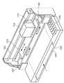
図1は、本発明の第1の実施形態としてのインクジェット記録装置の概略構成を示す斜視図である。
【0023】
記録装置100の給紙位置に挿入された記録媒体105は、送りローラ106によって矢印P方向に送られ、記録ヘッド104の記録可能領域へ搬送される。記録可能領域における記録媒体105の下部には、プラテン107が設けらている。キャリッジ101は、2つのガイド軸102と103によって、それらの軸方向に沿う方向に移動可能となっており、不図示のステッピングモータの駆動により、記録領域を含む走査領域を、主走査方向である矢印Q1、Q2で示す方向に沿って往復走査する。1回の主走査が終了すると、記録媒体を矢印P方向である副走査方向に一定量だけ送り次の主走査に備える。これらの主走査と副走査を繰り返して1頁の記録が行われる。なお、主走査方向の記録幅については、装置の設計上、機構的に記録ヘッドを走査可能な領域が決まっており、その走査領域に対応して最大の記録幅が装置によって決まっている。従って、記録装置における記録ヘッドの走査領域によって決まる記録幅の記録媒体、もしくはその記録幅よりも小さい記録媒体に対して記録が行えるよう構成されている。
【0024】
図1において、キャリッジ101に登載された記録ヘッド104は、インクを吐出可能な吐出口とインクを収容するインクタンクを含む構成であり、記録ヘッドの吐出口は下方に位置する記録媒体にインクを吐出して記録するようにキャリッジ上に搭載されている。また、108はスイッチ部と表示部であり、スイッチ部は記録装置の電源のオン/オフの切り替えや各種記録モードの設定等に使用され、表示部は記録装置の状態を表示可能に構成されてする。
【0025】
図2は、本実施形態のインクジェット記録装置100の主要な制御構成を示すブロック図である。記録装置100の外部にはホスト装置500が接続されており、ホスト装置200から記録装置100に記録すべき文字や画像のデータが送信され、受信バッファ201に蓄えられる。また、正しくデータが転送されているかどうかを確認するデータ、および記録装置100の動作状態を知らせるデータが記録装置100からホスト装置200に送信される。
【0026】
受信バッファ201に蓄えられたデータは、ROM211に格納された制御プログラムに従って動作するCPU202の管理下において、記録ヘッド104が主走査を行う時に記録を行うためのデータに加工され、ランダムアクセスメモリ(RAM)203内のプリントバッファに記憶される。プリントバッファは記録ヘッドによる記録に用いられるデータを格納するものであり、プリントバッファに格納されたデータを記録ヘッドへ転送することで記録が行われる。図3に示す例では、RAM403の記憶領域内にプリントバッファ用の領域が確保されている。プリントバッファのデータは、記録ヘッドコントロール部210により記録ヘッド104に転送され、記録ヘッドを制御して文字や画像のデータを記録する。また、記録ヘッドコントロール部210は、記録ヘッド104の状態を示す温度情報等を検出してCPU202に送り、記録ヘッドコントロール部210にその情報を伝達し、記録ヘッドを制御する。
【0027】
機構コントロール部204は、CPU202からの指令によりキャリッジモータやラインフィードモータ等の機構部205を駆動制御する。
【0028】
センサ/SWコントロール部206は、各種センサやSW(スイッチ)からなるセンサ/SW部407からの信号をCPU202に送る。
【0029】
表示素子コントロール部408は、CPU202からの指令により、表示パネル群のLEDや液晶表示素子等からなる表示部209を制御するよう構成されている。
【0030】
図3は、本実施形態に係る記録ヘッドを吐出面から見た状態を示す図である。図3に示した記録ヘッド104は、ブラックインクを吐出するブラックヘッドであり、1インチ当たりN=600個の密度(600dpi)で、n=300個の吐出口(ノズル)300を有している。記録ヘッドの駆動周波数は、15KHzであり、主走査方向に対して600dpiの密度で記録動作可能である。従って、記録動作時のキャリッジの主走査速度は25インチ/秒である。
【0031】
また、本実施形態におけるRAM203内のプリントバッファ部の容量は、記録密度が600dpi×600dpiの2値データを縦幅が記録ヘッドのノズル幅(吐出口数)に相当する300dot、横幅がA4サイズを1回走査するのに必要な横幅8インチ=4800dotの3/4に相当する6インチ=3600dotとする。つまり、プリントバッファとして確保するメモリ容量は、300×3600=1080000bit=1.08Mbitとする。
【0032】
本実施形態では、このようにプリントバッファの容量が、装置の設計上決まっている主走査方向の記録幅、つまりその装置における主走査方向の最大の記録幅に対して記録ヘッドを1回主走査して記録するデータ量よりも少ない容量に設定されている。つまり、装置の最大記録幅に対応して1主走査分の記録データを格納するのに必要な容量よりも小さな容量を、RAM403内に確保している。このように構成することで、装置に設けられるRAM403の記憶容量を小さくすることができる。このようにプリントバッファを構成し、記録が開始された後に、記録が終了した部分を順次再利用して循環的にプリントバッファにデータを格納しながら1回の主走査単位で記録を行う。
【0033】
本実施形態における記録方法は、300ノズルを有するブラックヘッドを用いた1回の主走査で記録を完成させる1パス記録で、図1にQ2で示す方向でのみ記録を行う片方向記録である。
【0034】
以下、図4の本実施形態による記録の進行状態を示す図を参照して記録動作について説明する。
【0035】
図2のホスト装置200は、1回の主走査で記録するデータを生成したら、記録装置100にデータを転送する。記録装置100は、ホスト装置200から縦幅300dot×横幅3600dot=1.08Mbitのプリントバッファの最大メモリ容量(設定値)のデータを受信し、プリントバッファに格納すると、記録媒体を記録開始位置まで搬送し、図中Aで示す位置からBで示す位置までQ2で示す方向に主走査を行い▲1▼で示す領域に記録を開始する。記録開始後は、上述のように、記録し終えたプリントバッファにホスト装置から送られてくるデータを順次格納しながら記録を行う。
【0036】
1回目の主走査での記録が終了すると、ブラックヘッドを搭載したキャリッジをBの位置からAの位置にQ1で示す方向に戻し、記録媒体を300dot分副走査方向に搬送(紙送り)して、2回目の主走査での記録を開始する。2回目の主走査も1回目の主走査と同様に、縦幅300dot×横幅3600dot=1.08Mbitの最大メモリ容量(設定値)のデータを受信してプリントバッファに格納した後、記録を開始する。
【0037】
この2回目の主走査においては、領域▲2▼の横幅3600dotを記録している間に、ホスト装置から送られてくるデータの受信が間に合わなかったと想定する。この場合、矢印Q2方向に領域▲2▼を記録した時点で、領域▲3▼のデータが未だプリントバッファに格納されていないため、領域▲3▼を記録せずに、一旦この記録走査を中断する。
【0038】
その後、この2回目の主走査を開始したAの位置までキャリッジを戻し、副走査方向への紙送りを行わずに、領域▲3▼の横幅に相当する、(4800dot)−(3600dot)=1200dotの、縦幅300dot×横幅1200dot=0.36Mbitの容量のデータ(中断した主走査の残りのデータ)がプリントバッファに格納されると、2回目の主走査を補完するための主走査を開始する。キャリッジが領域▲2▼と領域▲3▼の境界部分に達すると吐出を開始し、領域▲3▼の記録を完成させる。
【0039】
次に、ブラックヘッドを搭載したキャリッジをBの位置からAの位置にQ1の方向で戻し、記録媒体を300dot分副走査方向に搬送し、3回目の主走査での記録を開始する。この時、記録開始の前にプリントバッファに格納されるデータ量(設定値)を、1回目及び2回目の主走査での設定値(1.08Mbit)とは異なった値に設定する。例えば、3回目の主走査においては、横幅3000dotに相当する、縦幅300dot×横幅3000dot=0.9Mbitのメモリ容量(設定値)のデータを受信し、プリントバッファに格納した後、記録を開始する。
【0040】
この3回目の主走査においては、領域▲4▼の横幅3000dotを記録している間にホスト装置から送られてくるデータの受信が間に合わなかったと想定する。この場合、矢印Q2方向に領域▲4▼を記録した時点で、領域▲5▼のデータが未だプリントバッファに格納されていないため、領域▲5▼を記録せずに、一旦この記録走査を中断する。
【0041】
その後、この3回目の主走査を開始したAの位置までキャリッジを戻し、副走査方向への紙送りを行わずに、領域▲5▼の横幅に相当する、(4800dot)−(3000dot)=1800dotの、縦幅300dot×横幅1800dot=0.54Mbitの容量のデータ(中断した主走査の残りのデータ)がプリントバッファに格納されると、3回目の主走査を補完するための主走査を開始する。キャリッジが領域▲4▼と領域5の境界部分に達すると吐出を開始し、領域▲5▼の記録を完成させる。
【0042】
次に、ブラックヘッドを搭載したキャリッジをBの位置からAの位置にQ1の方向で戻し、記録媒体を300dot分副走査方向に搬送し、4回目の主走査での記録を開始する。この時、記録開始の前にプリントバッファに格納されるデータ量(設定値)を、1回目及び2回目の主走査での設定値(1.08Mbit)や3回目の主走査での設定値(0.9Mbit)とは異なった値に設定する。例えば、4回目の主走査においては、横幅2400dotに相当する、縦幅300dot×横幅2400dot=0.72Mbitのメモリ容量(設定値)のデータを受信し、プリントバッファに格納した後、記録を開始する。
【0043】
この4回目の主走査においては、プリントバッファに格納されたデータを記録している間に、ホスト装置からのデータ受信及び格納が順調に行われ、図4の▲6▼の領域をAからBの矢印Q2方向に、中断なしに1回の主走査で記録が行われた。
【0044】
不図示の5回目以降の主走査において、記録開始のトリガとなる設定値は、1回目の主走査と同様の最大メモリ容量に戻す。ただし、1回の主走査で記録を完了できずに再度補完するための主走査が行われた場合、次の主走査の設定値を、前の主走査での設定値よりも小さくし、1回の主走査での記録が中断されずに完了すると、次の主走査の設定値を、当初の最大メモリ容量に戻す。
【0045】
ここで図7のフローチャートを参照して、本実施形態での1ページの記録媒体に対する記録動作について再度説明する。
【0046】
ホスト装置200で起動されているアプリケーション上でプリントが指示されると、該ホスト装置200にインストールされているプリンタドライバは、プリントが指定されたファイル又はページのデータを記録装置100で記録可能なデータに変換して、記録装置100が1回の主走査で記録するデータ量を単位として記録装置に送信する。
【0047】
記録装置100では、ホスト装置200からプリントの指示コマンドを受信すると、受信してプリントバッファに格納されたデータが設定値に達するまで待つ(ステップS701)。本実施形態では1回目の主走査に対する設定値は、上述のようにプリントバッファの容量(1.08Mbit)と等しい。
【0048】
そして、プリントバッファに格納されたデータが設定値に達したら、主走査を開始して記録を実行し(ステップS702)、記録が終了した部分を順次再利用して循環的にプリントバッファに受信したデータを格納する(ステップS703)。このデータの受信・格納は、ホスト装置からの送信データが途絶え、データ受信が中断するまで続けられる。
【0049】
データの受信が中断したら(ステップS704)、主走査が完了したのかどうかを判定する(ステップS705)。これは例えば、キャリッジの位置等の情報からから判定できる。
【0050】
主走査が完了していない場合には、ホスト装置からのデータ転送が何らかの理由で途絶えたり転送速度が低下したものと認識し、一旦走査を中断してキャリッジを記録開始位置まで戻し、プリントバッファに中断した主走査で記録すべき残りのデータが格納されるのを待つ(ステップS706)。このデータ量は、上述のように、1回の主走査で記録するデータ量から設定値を減じた値である。
【0051】
残りのデータを受信しプリントバッファに格納したら、中断した主走査で記録されなかった部分を記録する補完記録を行い(ステップS707)、設定値を変更する(ステップS708)。この変更は、具体的には設定値を小さくするものであり、予め定められた値を減じてもよいし、ステップS706でのデータの受信に要した時間に応じた値を減じてもよい。
【0052】
ステップS705で主走査が完了したと判定された場合、及びステップS708での処理の後、記録媒体を記録ヘッドの使用ノズル数に相当する距離だけ搬送する副走査を行い(ステップS709)、1ページの記録が終了したか否かを判定する(ステップS710)。
【0053】
ステップS710で1ページの記録が終了したと判定されたら、記録媒体を排出して処理を終了する。一方、ステップS710で1ページの記録が終了していないと判定されたら、ステップS701へ戻り、以降の処理を繰り返す。
【0054】
以上のように、本実施形態によれば、1回の主走査で記録するデータ量よりも容量が小さいプリントバッファを備えた記録装置において、ホスト装置からのデータの転送が間に合わず、1回の主走査での記録が途中で中断された場合においても、記録されなかった領域に対する補完記録が行われ、1回の主走査に対応する領域の記録が完成される。
【0055】
特に、本実施形態においては、ホスト装置からのデータの送信が間に合わず、主走査での記録が中断される位置が、各主走査で異なるように制御する。具体的には、記録の途中で中断が発生すると、次の主走査を開始するまでにプリントバッファに格納されるデータ量(設定値)を所定量だけデクリメントして、ホスト装置からのデータ転送が間に合わずに記録が中断される位置が、記録開始位置へ近づくように制御するため、記録が中断された位置に発生する縦スジを走査方向において分散させることが可能になり、記録画質の劣化を防止できる。
【0056】
(第2の実施形態)
以下、本発明の第2の実施形態について説明する。第2の実施形態も上記第1の実施形態と同様なインクジェット記録装置であり、以下の説明では上記第1の実施形態と同様な部分については説明を省略し、本実施形態の特徴的な部分を中心に説明する。
【0057】
第1の実施形態は、図4のAからBへの矢印Q2で示す方向の主走査のみで記録を行う片方向記録を行うものであるが、本実施形態は、主走査毎に記録方向を異ならせる、すなわち、矢印Q2方向の記録と矢印Q1方向の記録とを交互に行う双方向記録を行うものである。
【0058】
以下、図5の本実施形態による記録の進行状態を示す図を参照して記録動作について説明する。
【0059】
図2のホスト装置200は、1回の主走査で記録するデータを生成したら、記録装置100にデータを転送する。記録装置100は、ホスト装置200から縦幅300dot×横幅3600dot=1.08Mbitのプリントバッファの最大メモリ容量(設定値)のデータを受信し、プリントバッファに格納すると、記録媒体を記録開始位置まで搬送し、図中Aで示す位置からBで示す位置までQ2で示す方向に主走査を行い▲1▼で示す領域に記録を開始する。記録開始後は、上述のように、記録し終えたプリントバッファにホスト装置から送られてくるデータを順次格納しながら記録を行う。
【0060】
1回目の主走査での記録が終了すると、記録媒体を300dot分副走査方向に搬送(紙送り)して、矢印Q1方向に2回目の主走査での記録を開始する。
【0061】
2回目の主走査も1回目の主走査と同様に、縦幅300dot×横幅3600dot=1.08Mbitの最大メモリ容量(設定値)のデータを受信しプリントバッファに格納した後、記録を開始する。
【0062】
この2回目の主走査においては、領域▲2▼の横幅3600dotを記録している間に、ホスト装置から送られてくるデータの受信が間に合わなかったと想定する。この場合、矢印Q1方向に領域▲2▼を記録した時点で、領域▲3▼のデータが未だプリントバッファに格納されていないため、領域▲3▼を記録せずに、一旦この記録走査を中断する。
【0063】
その後、この2回目の主走査を開始したBの位置までキャリッジを戻し、副走査方向への紙送りを行わずに、領域▲3▼の横幅に相当する、(4800dot)−(3600dot)=1200dotの、縦幅300dot×横幅1200dot=0.36Mbitの容量のデータ(中断した主走査の残りのデータ)がプリントバッファに格納されると、2回目の主走査を補完するための主走査を開始する。キャリッジが領域▲2▼と領域▲3▼の境界部分に達すると吐出を開始し、領域▲3▼の記録を完成させる。
【0064】
次に、記録媒体を300dot分副走査方向に送り、矢印Q2方向に3回目の主走査での記録を開始する。
【0065】
本実施形態では、3回目の主走査も1回目の主走査と同様に、縦幅300dot×横幅3600dot=1.08Mbitの最大メモリ容量(設定値)のデータを受信しプリントバッファに格納した後、記録を開始する。
【0066】
この3回目の主走査においては、領域▲4▼の横幅3600dotを記録している間にホスト装置から送られてくるデータの受信が間に合わなかったと想定する。この場合、矢印Q2方向に領域▲4▼を記録した時点で、領域▲5▼のデータが未だプリントバッファに格納されていないため、領域▲5▼を記録せずに、一旦この記録走査を中断する。
【0067】
その後、この3回目の主走査を開始したAの位置までキャリッジを戻し、副走査方向への紙送りを行わずに、領域▲5▼の横幅に相当する、(4800dot)−(3600dot)=1200dotの、縦幅300dot×横幅1200dot=0.36Mbitの容量のデータ(中断した主走査の残りのデータ)がプリントバッファに格納されると、3回目の主走査を補完するための主走査を開始する。キャリッジが領域▲4▼と領域▲5▼の境界部分に達すると吐出を開始し、領域▲5▼の記録を完成させる。
【0068】
次に、記録媒体を300dot分副走査方向に搬送し、矢印Q1方向に4回目での主走査の記録を開始する。この時、記録開始の前にプリントバッファに格納されるデータ量(設定値)を、2回目の主走査で用いた設定値(1.08Mbit)とは異なった値に設定する。例えば、4回目の主走査においては、横幅3000dotに相当する、縦幅300dot×横幅3000dot=0.9Mbitのメモリ容量(設定値)のデータを受信し、プリントバッファに格納した後、記録を開始する。
【0069】
この4回目の主走査においては、領域▲4▼の横幅3000dotを記録している間にホスト装置から送られてくるデータの受信が間に合わなかったと想定する。この場合、矢印Q1方向に領域▲6▼を記録した時点で、領域▲7▼のデータが未だプリントバッファに格納されていないため、領域▲7▼を記録せずに、一旦この記録走査を中断する。
【0070】
その後、この4回目の主走査を開始したBの位置までキャリッジを戻し、副走査方向への紙送りを行わずに、領域▲7▼の横幅に相当する、(4800dot)−(3000dot)=1800dotの、縦幅300dot×横幅1800dot=0.54Mbitの容量のデータ(中断した主走査の残りのデータ)がプリントバッファに格納されると、4回目の主走査を補完するための主走査を開始する。キャリッジが領域▲6▼と領域▲7▼の境界部分に達すると吐出を開始し、領域▲7▼の記録を完成させる。
【0071】
次に、記録媒体を300dot分副走査方向に搬送し、5回目の主走査での記録を開始する。この時、記録開始の前にプリントバッファに格納するデータ量(設定値)は、1回目の主走査及び3回目の主走査で用いた設定値(1.08Mbit)とは異なった値に設定する。例えば、5回目の主走査においては、横幅3000dotに相当する、縦幅300dot×3000dot=0.9Mbitのメモリ容量(設定値)のデータを受信しプリントバッファに格納した後、記録を開始する。
【0072】
この5回目の主走査においては、プリントバッファに格納されたデータを記録している間に、ホスト装置からのデータ受信及び格納が順調に行われ、図5の▲8▼の領域をAからBの矢印Q2方向に、中断なしに1回の主走査で記録が行われた。
【0073】
次に、記録媒体を300dot分副走査方向に搬送し、6回目の主走査での記録を開始する。この時、記録開始の前にプリントバッファに格納されるデータ量(設定値)は、2回目の主走査で用いた設定値や4回目の主走査で用いた設定値と異なった値に設定する。例えば、6回目の主走査においては、横幅2400dotに相当する、縦幅300dot×2400dot=0.72Mbitのメモリ容量(設定値)のデータを受信しプリントバッファに格納された後、記録を開始する。
【0074】
この6回目の主走査においては、プリントバッファに格納されたデータを記録している間に、ホスト装置からのデータ受信及び格納が順調に行われ、図5の▲9▼の領域をAからBの矢印Q2方向に、中断なしに1回の主走査で記録が行われた。
【0075】
不図示の7回目以降の主走査において、記録開始のトリガとなる設定値は、1回目及び2回目の主走査と同様の最大メモリ容量に戻す。ただし、1回の主走査分で記録を完了できずに再度補完するための主走査が行われた場合、同じ方向への次の主走査の設定値を、前回の同じ方向への主走査の設定値よりも小さくし、1回の主走査での記録が中断されずに完了すると、次の主走査の設定値を当初の最大メモリ容量に戻す。
【0076】
このように、本実施形態では、矢印Q2方向への往路方向の主走査と矢印Q1方向への復路方向の主走査とに対して、記録開始のための条件(設定値)を独立して制御する。
【0077】
なお、本実施形態での1ページの記録媒体に対する記録動作は、各主走査毎に走査方向が異なる点以外は第1の実施形態とほぼ同様であるが、走査方向に対応して2つの設定値を設け、図7のフローチャートのステップS708で、走査方向に応じた設定値を変更するようにすればよい。
【0078】
以上のように、本実施形態によれば、1回の主走査で記録するデータ量よりも容量が小さいプリントバッファを備え、双方向記録を行う記録装置において、ホスト装置からのデータの転送が間に合わず、1回の主走査での記録が途中で中断された場合においても、記録されなかった領域に対する補完記録が行われ、1回の主走査に対応する領域の記録が完成される。
【0079】
特に、本実施形態においては、ホスト装置からのデータの送信が間に合わず、主走査での記録が中断される位置が、各走査方向での主走査毎に異なるように制御する。具体的には、ある走査方向の記録で中断が発生すると、同じ方向の次の主走査を開始するまでにプリントバッファに格納されるデータ量(設定値)を所定量だけデクリメントして、ホスト装置からのデータ転送が間に合わずに記録が中断される位置が、記録開始位置へ近づくように制御するため、記録が中断された位置に発生する縦スジを、それぞれの走査方向において分散させることが可能になり、記録画質の劣化を防止できる。
【0080】
(第3の実施形態)
以下、本発明の第3の実施形態について説明する。第3の実施形態も上記の実施形態と同様なインクジェット記録装置であり、以下の説明では上記の実施形態と同様な部分については説明を省略し、本実施形態の特徴的な部分を中心に説明する。
【0081】
上記第1及び第2の実施形態はいずれも、各記録領域の記録を1回の主走査で完成させる、いわゆる1パス記録を行うものであるが、第3の実施形態は、各記録領域に対して複数回の主走査を行う、マルチパス記録を行うものである。
【0082】
具体的には、各記録領域に対して、矢印Q2方向への主走査を3回ずつ行う。使用する記録ヘッドは、1/600インチのピッチで配列された、300個のノズルを有するブラックヘッドであり、1回の副走査で100ノズルに相当する距離だけ記録媒体の搬送を行う。
【0083】
本実施形態におけるRAM203内のプリントバッファ部の容量は、第1及び第2の実施形態と同様に、記録密度が600dpi×600dpiの2値データを、縦幅が記録ヘッドのノズル幅に相当する300dot、横幅がA4サイズを1走査するのに必要な横幅8インチ=4800dotの3/4に相当する6インチ=3600dot分のデータを格納できる容量とする。つまり、プリントバッファとして確保するメモリ容量は、300×3600=1080000bit=1.08Mbitとする。
【0084】
以下、図6の本実施形態による記録の進行状態を示す図を参照して記録動作について説明する。
【0085】
図2のホスト装置200は、1回の主走査で記録するデータを生成したら、記録装置100にデータを転送する。記録装置100は、1回目の主走査で記録する領域、縦幅100dot×横幅4800dot=0.48Mbitのメモリ容量(設定値)のデータを受信し、プリントバッファに格納すると、図6(a)に示すように、300ノズルの内1/3の100ノズルを使用して、▲1▼の領域をAからBまで矢印Q2方向に主走査して記録を行う。
【0086】
1回目の主走査での記録が終了すると、ブラックヘッドを搭載したキャリッジを矢印Q1の方向でBの位置からAの位置まで戻し、記録媒体を100dot分矢印Pの副走査方向に搬送する。
【0087】
次に、2回目の主走査で記録する領域、縦幅200dot×横幅4800dot=0.96Mbitのメモリ容量(設定値)のデータを受信し、プリントバッファに格納すると、図6(b)に示すように、300ノズルの内2/3の200ノズルを使用して、▲2▼の領域をAからBまで矢印Q2方向に主走査して記録を行う。
【0088】
2回目の主走査での記録が終了すると、ブラックヘッドを搭載したキャリッジを矢印Q1の方向でBの位置からAの位置まで戻し、記録媒体を100dot分矢印Pの副走査方向に搬送する。
【0089】
次に、3回目の主走査で記録する領域、縦幅300dot×横幅3600dot=1.08Mbitの最大メモリ容量(設定値)のデータを受信し、プリントバッファに格納すると、図6(c)に示すように、300ノズル全てを使用して、▲3▼の領域をAからBまで矢印Q2方向に記録を開始する。
【0090】
この3回目の主走査においては、領域▲3▼の横幅3600dotを記録している間に、ホスト装置から送られてくるデータの受信できなかったと想定する。この場合、矢印Q2方向に領域▲3▼を記録した時点で、領域▲3▼以降のデータが未だプリントバッファに格納されていないため、領域▲3▼以降の領域を記録せずに、一旦この記録走査を中断する。
【0091】
その後、この3回目の主走査を開始したAの位置までキャリッジを戻し、副走査方向への紙送りを行わずに、領域▲3▼以降の横幅に相当する(4800dot)−(3600dot)=1200dotの、縦幅300dot×横幅1200dot=0.36Mbitの容量のデータ(中断した主走査の残りのデータ)がプリントバッファに格納されると、3回目の主走査を補完するための主走査を開始する。図6(d)に示すように、キャリッジが領域▲4▼に達すると吐出を開始し、矢印Q2方向にB位置まで記録を行う。
【0092】
次に、ブラックヘッドを搭載したキャリッジをBの位置からAの位置にQ1の方向で戻し、記録媒体を100dot分矢印Pの副走査方向に搬送し、4回目の主走査での記録を開始する。この時、記録開始の前にプリントバッファに格納されるデータ量(設定値)を、3回目の主走査での設定値(1.08Mbit)とは異なった値に設定する。例えば、4回目の主走査においては、横幅300dotに相当する、縦幅300dot×横幅3000dot=0.9Mbitのメモリ容量(設定値)のデータを受信し、プリントバッファに格納した後、記録を開始する。
【0093】
この4回目の主走査においては、プリントバッファに格納されたデータを記録している間に、ホスト装置からのデータ受信及び格納が順調に行われ、図6(e)で示すように、▲5▼の領域をAからBの矢印Q2方向に、中断なしに1回の主走査で記録が行われた。
【0094】
次に、ブラックヘッドを搭載したキャリッジをBの位置からAの位置にQ1の方向で戻し、記録媒体を100dot分矢印Pの副走査方向に搬送し、5回目の主走査での記録を開始する。記録開始の前にプリントバッファに格納されるデータ量(設定値)を、3回目及び4回目の主走査での設定値とは異なった値に設定する。例えば、5回目の主走査においては、横幅2400dotの縦幅300dot×横幅2400dot=0.72Mbitのメモリ容量(設定値)のデータを受信し、プリントバッファに格納すると記録を開始する。
【0095】
この5回目の主走査においては、プリントバッファに格納されたデータを記録している間に、ホスト装置からのデータ受信及び格納が順調に行われ、図6(f)で示すように、▲6▼の領域をAからBの矢印Q2方向に、中断なしに1回の主走査で記録が行われた。
【0096】
不図示の6回目以降の主走査については、記録開始のトリガとなる設定値は、3回目の主走査と同様の300ノズル使用時の最大メモリ容量とする。ただし、1回の主走査で記録を完了できずに再度補完するための主走査が行われた場合、以降のマルチパス回数(3回)分の主走査の設定値を、それぞれ異なった値に設定し、1回の主走査での記録が中断されずに完了すると、次の主走査の設定値を、当初の最大メモリ容量に戻す。
【0097】
なお、本実施形態での1ページの記録媒体に対する記録動作は、1回目及び2回目と記録終了前の2回の各主走査に対する設定値が異なる点以外は第1の実施形態とほぼ同様であるが、記録が中断した後、マルチパス回数分の主走査それぞれに対して設定値を異ならせるように、図7のフローチャートのステップS708で、記録が中断されたことを示すフラグをたて、以降のマルチパス回数分の主走査で設定値を変更するようにすればよい。
【0098】
以上のように、本実施形態によれば、1回の主走査で記録するデータ量よりも容量が小さいプリントバッファを備え、マルチパス記録を行う記録装置において、ホスト装置からのデータの転送が間に合わず、1回の主走査での記録が途中で中断された場合においても、記録されなかった領域に対する補完記録が行われ、1回の主走査に対応する領域の記録が完成される。
【0099】
特に、本実施形態においては、ホスト装置からのデータの送信が間に合わず、主走査での記録が中断される位置が、各主走査で異なるように制御する。具体的には、記録の途中で中断が発生すると、次の主走査を開始するまでにプリントバッファに格納されるデータ量(設定値)を所定量だけデクリメントして、ホスト装置からのデータ転送が間に合わずに記録が中断される位置が、記録開始位置へ近づくように制御するため、マルチパス記録で、記録が中断された位置に発生する縦スジを走査方向において分散させることが可能になり、記録画質の劣化を防止できる。
【0100】
[その他の実施形態]
上記の実施形態ではプリントバッファの容量を、1回の主走査で記録されるデータ量の3/4としたが、プリントバッファの容量は、この値に限定されるものではない。
【0101】
また、プリントバッファの容量が、1回の主走査で記録されるデータ量より多い場合には、ホスト装置からのデータ転送速度に応じて、主走査の記録開始条件である設定値の値を、1回の走査で記録されるデータ量未満として、記録開始までの時間を短縮するようにしてもよく、あるいは、主走査の記録開始条件である設定値の値を、1回の主走査で記録されるデータ量以上として記録の中断を防止するようにすることもできる。
【0102】
この場合、ホスト装置からのデータ転送速度を監視する手段を設け、データ転送速度に応じて設定値を変更すると、記録の中断の発生をより効率的に防止できる。
【0103】
また、上記の実施形態では、A4サイズの記録媒体に、記録解像度が600×600dpiで、1画素当りのデータ量が1bitのモノクロの記録データを、600dpiで300個のノズルを有する記録ヘッドで記録する場合を例に挙げて説明したが、記録媒体のサイズ、記録解像度、記録データの1画素当りのデータ量、記録データの色数、及び記録ヘッドのノズル数は、上記以外であってもよい。この場合、記録媒体のサイズ、記録解像度、記録データの1画素当りのデータ量、記録データの色数、及び記録ヘッドのノズル数の少なくとも1つに応じて、設定値の値を変更するようにするとよい。
【0104】
また、上記の実施形態では通常の記録において記録を開始するトリガとなる設定値を、プリントバッファの容量と等しい最大メモリ容量としていたが、設定値の初期値はこれらの値に限定されず、プリントバッファの容量未満であっても良い。
【0105】
更に、補完のための主走査を、残りの領域の記録データが全てプリントバッファに格納された後に開始するものとしたが、この場合にも、通常の主走査と同様に、残りの領域の記録データが全てプリントバッファに格納される前に、主走査を開始するようにしてもよい。この場合の設定値は、通常の主走査と同じであってもよいし、異なっていてもよい。
【0106】
また、第3の実施形態においては、主走査が中断された場合、以降のマルチパス回数分の主走査に対する設定値をそれぞれ異ならせるものとしたが、同じ値が含まれていてもよい。
【0107】
また、上記の実施形態において、記録が中断された際には、キャリッジを記録開始位置まで戻して補完のための主走査を行うものとしたが、補完のための主走査の開始位置は通常の記録開始位置に限定されず、補完のための主走査が実行可能な位置であれば他の位置でもよい。
【0108】
具体的には、記録が中断された際に、キャリッジを一旦ホームポジションあるいは予備吐出可能な位置まで戻し、補完記録を行う前に予備吐出を実施すると、補完記録を行うまでの間に生じるインクの増粘に起因する記録画像の縦スジの発生を防止することができる。
【0109】
更にまた、上記実施形態においては、1/600インチのピッチで配列された300個のノズルを有するブラックヘッドのみを使用してモノクロ記録を行う記録装置について説明したが、シアン、マゼンタ、イエロー等の異なる色のインクを用い、各色に対応した記録ヘッドを用いてカラー記録を行う記録装置に対しても本発明は適用できる。
【0110】
この場合、1/600インチのピッチで配列されたノズルを100個有する記録ヘッドを3つの色に対応して備えた構成とし、各色の記録データを縦幅100ノズル分の記録データに割り当てれば、第3の実施形態と同様の制御を用いることができ、同様の効果を得ることができる
また、プリントバッファを複数に分割してブロック単位で取り扱うこととし、記録開始のトリガとなる設定値をブロック単位としても良く、中断する場合の位置をブロックの記録領域に対応させてもよい。また、本実施形態においては。プリントバッファに格納されたデータが記録された後に記録を中断するものとしたが、これに限定されず、格納されたデータ量又は格納可能なデータ量又はその両方を監視しながら記録を中断する位置を制御しても良い。
【0111】
また、以上の実施形態の説明は、インクジェット記録装置を例に挙げて説明したが、本発明は記録ヘッドを記録媒体上で走査させて記録を行うシリアル型の記録装置であれば、インクジェット以外の他の記録方式を用いた記録装置にも適用できる。
【0112】
以上の実施形態は、特にインクジェット記録方式の中でも、インク吐出を行わせるために利用されるエネルギーとして熱エネルギーを発生する手段(例えば電気熱変換体やレーザ光等)を備え、前記熱エネルギーによりインクの状態変化を生起させる方式を用いることにより記録の高密度化、高精細化が達成できる。
【0113】
その代表的な構成や原理については、例えば、米国特許第4723129号明細書、同第4740796号明細書に開示されている基本的な原理を用いて行うものが好ましい。この方式はいわゆるオンデマンド型、コンティニュアス型のいずれにも適用可能であるが、特に、オンデマンド型の場合には、液体(インク)が保持されているシートや液路に対応して配置されている電気熱変換体に、記録情報に対応していて核沸騰を越える急速な温度上昇を与える少なくとも1つの駆動信号を印加することによって、電気熱変換体に熱エネルギーを発生せしめ、記録ヘッドの熱作用面に膜沸騰を生じさせて、結果的にこの駆動信号に1対1で対応した液体(インク)内の気泡を形成できるので有効である。
【0114】
この気泡の成長、収縮により吐出用開口を介して液体(インク)を吐出させて、少なくとも1つの滴を形成する。この駆動信号をパルス形状とすると、即時適切に気泡の成長収縮が行われるので、特に応答性に優れた液体(インク)の吐出が達成でき、より好ましい。
【0115】
このパルス形状の駆動信号としては、米国特許第4463359号明細書、同第4345262号明細書に記載されているようなものが適している。なお、上記熱作用面の温度上昇率に関する発明の米国特許第4313124号明細書に記載されている条件を採用すると、さらに優れた記録を行うことができる。
【0116】
記録ヘッドの構成としては、上述の各明細書に開示されているような吐出口、液路、電気熱変換体の組み合わせ構成(直線状液流路または直角液流路)の他に熱作用面が屈曲する領域に配置されている構成を開示する米国特許第4558333号明細書、米国特許第4459600号明細書に記載された構成も本発明に含まれるものである。加えて、複数の電気熱変換体に対して、共通するスロットを電気熱変換体の吐出部とする構成を開示する特開昭59−123670号公報や熱エネルギーの圧力波を吸収する開口を吐出部に対応させる構成を開示する特開昭59−138461号公報に基づいた構成としても良い。
【0117】
加えて、上記の実施形態で説明した記録ヘッド自体に一体的にインクタンクが設けられたカートリッジタイプの記録ヘッドのみならず、装置本体に装着されることで、装置本体との電気的な接続や装置本体からのインクの供給が可能になる交換自在のチップタイプの記録ヘッドを用いてもよい。
【0118】
また、以上説明した記録装置の構成に、記録ヘッドに対する回復手段、予備的な手段等を付加することは記録動作を一層安定にできるので好ましいものである。これらを具体的に挙げれば、記録ヘッドに対してのキャッピング手段、クリーニング手段、加圧あるいは吸引手段、電気熱変換体あるいはこれとは別の加熱素子あるいはこれらの組み合わせによる予備加熱手段などがある。また、記録とは別の吐出を行う予備吐出モードを備えることも安定した記録を行うために有効である。
【0119】
さらに、記録装置の記録モードとしては黒色等の主流色のみの記録モードだけではなく、記録ヘッドを一体的に構成するか複数個の組み合わせによってでも良いが、異なる色の複色カラー、または混色によるフルカラーの少なくとも1つを備えた装置とすることもできる。
【0120】
なお、本発明は、複数の機器(例えばホストコンピュータ,インターフェース機器,リーダ,プリンタなど)から構成されるシステムに適用しても、一つの機器からなる装置(例えば、複写機,ファクシミリ装置など)に適用してもよい。
また、本発明の目的は、前述した実施形態の機能を実現するソフトウェアのプログラムコードを記録した記憶媒体を、システムあるいは装置に供給し、そのシステムあるいは装置のコンピュータ(またはCPUやMPU)が記憶媒体に格納されたプログラムコードを読出し実行することによっても、達成されることは言うまでもない。
【0121】
この場合、記憶媒体から読出されたプログラムコード自体が前述した実施形態の機能を実現することになり、そのプログラムコードを記憶した記憶媒体は本発明を構成することになる。
【0122】
プログラムコードを供給するための記憶媒体としては、例えば、フロッピディスク,ハードディスク,光ディスク,光磁気ディスク,CD−ROM,CD−R,磁気テープ,不揮発性のメモリカード,ROMなどを用いることができる。
【0123】
また、コンピュータが読出したプログラムコードを実行することにより、前述した実施形態の機能が実現されるだけでなく、そのプログラムコードの指示に基づき、コンピュータ上で稼働しているOS(オペレーティングシステム)などが実際の処理の一部または全部を行い、その処理によって前述した実施形態の機能が実現される場合も含まれることは言うまでもない。
【0124】
さらに、記憶媒体から読出されたプログラムコードが、コンピュータに挿入された機能拡張ボードやコンピュータに接続された機能拡張ユニットに備わるメモリに書込まれた後、そのプログラムコードの指示に基づき、その機能拡張ボードや機能拡張ユニットに備わるCPUなどが実際の処理の一部または全部を行い、その処理によって前述した実施形態の機能が実現される場合も含まれることは言うまでもない。
【0125】
本発明を上記記憶媒体に適用する場合、その記憶媒体には、先に説明した(図7に示す)フローチャートに対応するプログラムコードが格納されることになる。
【0126】
【発明の効果】
以上説明したように本発明によれば、記録データを格納するバッファに、1回の走査で記録ヘッドが記録媒体に記録する記録データの量よりも少ない第1の量だけ記録データが格納された時点で記録走査が開始され、走査の間に、バッファへの記録データの格納が間に合わない場合には該記録走査を中断し、後続する記録データが第2の量だけバッファに格納されると、中断された走査を実行して1回の走査の記録を完成させる。
【0127】
従って、第1の量及び第2の量を適切に設定することにより、1回の主走査で記録するデータ量よりも少ない容量のメモリを備える安価な構成で、記録走査の中断の発生を抑制しつつ、記録走査が途中で中断された場合においても、高画質の記録を行うことが可能となる。
【図面の簡単な説明】
【図1】本発明の第1の実施形態としてのインクジェット記録装置の概略構成を示す斜視図である。
【図2】第1の実施形態のインクジェット記録装置の主要な制御構成を示すブロック図である。
【図3】第1の実施形態に係る記録ヘッドを吐出面から見た状態を示す図である。
【図4】第1の実施形態による記録の進行状態を示す図である。
【図5】第2の実施形態による記録の進行状態を示す図である。
【図6】第3の実施形態による記録の進行状態を示す図である。
【図7】第1の実施形態での1ページの記録媒体に対する記録動作を示すフローチャートである。
【符号の説明】
100 記録装置
101 キャリッジ
102 ガイド軸a
103 ガイド軸b
104 記録ヘッド
105 記録媒体
106 送りローラ
107 プラテン
108 スイッチ部と表示部
200 ホスト装置
201 受信バッファ
202 CPU
203 ランダムアクセスメモリ部
204 機構コントロール部
205 機構部
206 センサ/SWコントロール部
207 センサ/SW部
208 表示素子コントロール部
209 表示素子部
210 記録ヘッドコントロール部[0001]
BACKGROUND OF THE INVENTION
The present invention relates to a recording apparatus and a recording method, and in particular, a recording head having recording element arrays arranged in a predetermined direction on a recording medium in a direction crossing the arrangement direction based on information transmitted from a host apparatus. The present invention relates to a recording apparatus that performs recording by scanning. More specifically, the present invention relates to a recording apparatus and a recording method that enable high-speed and high-quality recording while reducing the cost of the recording apparatus by reducing the capacity of a storage unit (memory) provided in the recording apparatus.
[0002]
[Prior art]
Currently, various methods are known as recording methods used when recording information. However, the inkjet recording method is low noise, low device cost, low running cost, and small device. Therefore, it is widely used in recording devices and copying machines.
[0003]
2. Description of the Related Art Conventionally, a serial type ink jet recording apparatus is configured to record one page by alternately repeating main scanning by a recording head and sub-scanning for transporting a recording medium. Therefore, as a print buffer for storing data to be recorded by the recording head, a memory sufficient to store all data to be recorded in one main scanning with respect to a recording width in the main scanning direction that can be recorded by the recording apparatus Control is performed in such a manner that all data to be recorded in the main memory is stored in the print buffer and is recorded in the print buffer after the main scanning of the recording head is started.
[0004]
In recent years, the number of recording heads and the number of recording elements (ink ejection elements) provided in each recording head have tended to increase in order to achieve colorization, high image quality, high resolution, and high-speed recording. is there.
[0005]
[Problems to be solved by the invention]
As the number of recording heads and the number of recording elements provided in the recording head increase in this way, the amount of data to be recorded in one main scan also increases, so that the memory capacity required for the print buffer increases, and the entire apparatus increases. Cost becomes high.
[0006]
In order to prevent this, Japanese Patent Application Laid-Open No. 58-146929 discloses a memory capacity that is smaller than the amount of data recorded in one main scan by managing the address where the recording data is stored and efficiently using the memory. Thus, a technique for recording is disclosed.
[0007]
However, this publication does not describe the handling of null data, which is data indicating that recording is not performed, and it cannot be said that the use of memory is optimally made efficient. Also, it is not disclosed how to perform the recording operation when the data transfer to the memory is not in time during the recording operation.
[0008]
Japanese Patent Application Laid-Open No. 11-259248 discloses a technique for starting main scanning before reception of data for one main scanning is completed.
[0009]
However, the technique disclosed in this publication is based on the premise that recording data is received before actual recording in the main scanning. Therefore, for example, a host device such as a computer that transfers recording data to a recording device needs to continuously transfer data without interruption or interruption while recording is being performed.
[0010]
Windows System (registered trademark), which is widely used as an OS of computers these days, is a versatile multi-tact, and the computer hardly actually performs only data transfer during recording. Alternatively, the printer driver program installed on the computer can be used to perform data transfer continuously without interruption or interference. However, this does not eliminate the advantage of a multitasking system. Arise. Also, this publication does not describe handling of null data, which is data indicating that recording is not performed, and it cannot be said that the use of memory is optimally made efficient.
[0011]
Such a problem is common to all types of serial-type recording apparatuses, not just inkjet-type recording apparatuses.
[0012]
The present invention has been made in view of the situation as described above, and has a throughput as a configuration in which recording is started before the recording data transmitted from the host reaches an amount corresponding to one main scanning of the recording head. It is an object of the present invention to provide a recording apparatus and a recording method that can improve the recording quality and can perform high-quality recording even when data transfer from a host device is not in time. In addition, the present invention is an inexpensive configuration including a memory having a capacity smaller than the amount of data to be recorded in one main scan, and improves the throughput, and the recording operation during scanning without data transfer from the host device in time. An object of the present invention is to provide a recording apparatus and a recording method that can perform high-quality recording even when the recording is interrupted.
[0013]
[Means for Solving the Problems]
In order to achieve the above object, a recording apparatus of the present invention has a recording medium having a recording element array arranged in a predetermined direction on the basis of information transmitted from a host device, in a direction intersecting the arrangement direction. A recording apparatus that performs recording by scanning above,
Stores recording data transmitted from the host device Record A buffer,
Said Record Start control means for starting recording by scanning after the recording data stored in the buffer reaches a first amount smaller than the amount of recording data recorded by the recording head on the recording medium in one scan When,
During the scan, the Record If the recording data cannot be stored in the buffer in time, recording interruption means for interrupting the recording by the scanning;
After the interruption of the recording, Record Supplementary recording means for performing recording in an unrecorded area of the recording medium due to the interruption of the recording after the subsequent recording data stored in the buffer reaches the second amount;
Setting change means for reducing the first amount for the next scan by a predetermined amount when the interruption occurs; Is provided.
[0014]
Further, the object is to perform recording by causing a recording head having recording element arrays arranged in a predetermined direction to scan on a recording medium in a direction crossing the arrangement direction based on information transmitted from the host device. A recording method,
A storage step of storing the recording data transmitted from the host device in a buffer;
Start of recording by scanning when the recording data stored in the buffer reaches a first amount less than the amount of recording data that the recording head records on the recording medium in one scan Control process;
A scan interruption step of interrupting the scan if the recording data cannot be stored in the buffer during the scan;
After the interruption, a complementary recording step of executing the interrupted scanning to complete one scanning recording when the subsequent recording data stored in the buffer reaches a second amount; It is also achieved by the recording method of the present invention comprising:
[0015]
That is, in the present invention, recording is performed by causing a recording head having recording element arrays arranged in a predetermined direction to scan on a recording medium in a direction crossing the arrangement direction based on information transmitted from the host device. In the recording apparatus, the recording data transmitted from the host device is stored in a buffer, and the recording data stored in the buffer is less than the amount of recording data that the recording head records on the recording medium in one scan. When the amount is reached, recording by scanning is started, and if the recording data cannot be stored in the buffer in time during the scanning, the scanning is interrupted, and subsequent recording data stored in the buffer after the interruption However, when the second amount is reached, the interrupted scan is executed to complete the recording of one scan.
[0016]
In this way, the recording scan starts when the recording data is stored in the buffer for storing the recording data by the first amount smaller than the amount of the recording data that the recording head records on the recording medium in one scan. If the recording data cannot be stored in the buffer in time during the scanning, the recording scanning is interrupted. When the subsequent recording data is stored in the buffer by the second amount, the interrupted scanning is executed. Thus, the recording for one scan is completed.
[0017]
Therefore, by appropriately setting the first amount and the second amount, it is possible to suppress the interruption of the recording scan with an inexpensive configuration including a memory having a capacity smaller than the amount of data to be recorded in one main scan. However, even when the recording scan is interrupted, high-quality recording can be performed.
[0018]
DETAILED DESCRIPTION OF THE INVENTION
Preferred embodiments of the present invention will be described below in detail with reference to the accompanying drawings.
[0019]
In this specification, “recording” (sometimes referred to as “printing”) is not only for forming significant information such as characters and graphics, but also for human beings, regardless of whether it is significant or not. Regardless of whether or not it has been manifested, it also represents a case where an image, a pattern, a pattern or the like is widely formed on a recording medium or the medium is processed.
[0020]
“Recording medium” refers not only to paper used in general recording apparatuses but also widely to cloth, plastic film, metal plate, glass, ceramics, wood, leather, and the like that can accept ink. Shall.
[0021]
Furthermore, “ink” (sometimes referred to as “liquid”) is to be interpreted broadly in the same way as the definition of “recording (printing)” above. It represents a liquid that can be used for forming a pattern or the like, processing a recording medium, or processing an ink (for example, solidification or insolubilization of a colorant in ink applied to the recording medium).
[0022]
(First embodiment)
FIG. 1 is a perspective view showing a schematic configuration of an ink jet recording apparatus as a first embodiment of the present invention.
[0023]
The
[0024]
In FIG. 1, a
[0025]
FIG. 2 is a block diagram showing the main control configuration of the
[0026]
Data stored in the
[0027]
The
[0028]
The sensor /
[0029]
The display element control unit 408 is configured to control the
[0030]
FIG. 3 is a diagram illustrating a state in which the recording head according to the present embodiment is viewed from the ejection surface. The
[0031]
The capacity of the print buffer in the
[0032]
In this embodiment, the print buffer capacity is set to the main scanning direction recording width determined by the design of the apparatus, that is, the recording head is scanned once for the maximum recording width in the main scanning direction of the apparatus. Thus, the capacity is set smaller than the amount of data to be recorded. That is, the RAM 403 has a capacity smaller than that required to store print data for one main scan corresponding to the maximum print width of the apparatus. With this configuration, the storage capacity of the RAM 403 provided in the apparatus can be reduced. In this way, the print buffer is configured, and after the start of recording, recording is performed in one main scanning unit while sequentially reusing the portions where recording has been completed and cyclically storing data in the print buffer.
[0033]
The recording method in the present embodiment is one-pass recording in which recording is completed by one main scanning using a black head having 300 nozzles, and recording is performed only in the direction indicated by Q2 in FIG.
[0034]
Hereinafter, the recording operation will be described with reference to FIG. 4 showing the progress of recording according to the present embodiment.
[0035]
When the
[0036]
When the first main scanning recording is completed, the carriage on which the black head is mounted is returned from the position B to the position A in the direction indicated by Q1, and the recording medium is conveyed (paper fed) in the sub-scanning direction by 300 dots. Recording in the second main scan is started. Similarly to the first main scan, the second main scan receives data having a maximum memory capacity (setting value) of 300 dots in length × 3600 dots in width = 1.08 Mbit, stores the data in the print buffer, and then starts recording. .
[0037]
In the second main scanning, it is assumed that the data received from the host device was not received in time while the horizontal width 3600 dots of the area (2) was recorded. In this case, when the area (2) is recorded in the direction of the arrow Q2, since the data of the area (3) is not yet stored in the print buffer, the recording scan is temporarily interrupted without recording the area (3). To do.
[0038]
Thereafter, the carriage is returned to the position A where the second main scanning is started, and the paper is not fed in the sub-scanning direction, and corresponds to the horizontal width of the region (3), (4800 dots) − (3600 dots) = 1200 dots. When the data having a capacity of 300 dots in length × 1200 dots in width = 0.36 Mbit (remaining data of the interrupted main scan) is stored in the print buffer, main scan for complementing the second main scan is started. . When the carriage reaches the boundary between the area {circle around (2)} and the area {circle around (3)}, the ejection is started and the recording of the area {circle around (3)} is completed.
[0039]
Next, the carriage on which the black head is mounted is returned from the position B to the position A in the Q1 direction, the recording medium is conveyed by 300 dots in the sub-scanning direction, and recording in the third main scanning is started. At this time, the data amount (set value) stored in the print buffer before the start of printing is set to a value different from the set value (1.08 Mbit) in the first and second main scans. For example, in the third main scan, data having a memory capacity (setting value) of 300 dots in length × 3000 dots in width = 0.9 Mbit corresponding to a width of 3000 dots is received, stored in the print buffer, and then recording is started. .
[0040]
In the third main scan, it is assumed that the data received from the host device was not received in time while the horizontal width of 3000 dots of the area (4) was recorded. In this case, when the area (4) is recorded in the direction of the arrow Q2, since the data of the area (5) is not yet stored in the print buffer, the recording scan is temporarily interrupted without recording the area (5). To do.
[0041]
Thereafter, the carriage is returned to the position A where the third main scanning is started, and the paper is not fed in the sub-scanning direction, and corresponds to the horizontal width of the area (5), (4800 dots) − (3000 dots) = 1800 dots. When data having a capacity of 300 dots in length × 1800 dots in width = 0.54 Mbit (remaining data of the interrupted main scan) is stored in the print buffer, main scan for complementing the third main scan is started. . When the carriage reaches the boundary between the area (4) and the
[0042]
Next, the carriage on which the black head is mounted is returned from the position B to the position A in the Q1 direction, the recording medium is conveyed in the sub-scanning direction by 300 dots, and recording in the fourth main scanning is started. At this time, the amount of data (set value) stored in the print buffer before the start of printing is set to the set value (1.08 Mbit) in the first and second main scans or the set value (1.08 Mbit) in the third main scan ( It is set to a value different from 0.9 Mbit). For example, in the fourth main scan, data having a memory capacity (setting value) of 300 dots in length × 2400 dots in width × 0.72 Mbit corresponding to 2400 dots in width is received, stored in the print buffer, and then recording is started. .
[0043]
In the fourth main scan, while the data stored in the print buffer is being recorded, the reception and storage of data from the host device are performed smoothly, and the area (6) in FIG. In the direction of arrow Q2, recording was performed in one main scan without interruption.
[0044]
In the main scanning (not shown) from the fifth time onward, the set value that triggers the start of printing is returned to the maximum memory capacity similar to that in the first main scanning. However, when the main scan for complementation is performed again without completing printing in one main scan, the set value for the next main scan is made smaller than the set value for the previous main scan, and 1 When printing in the main scanning is completed without interruption, the setting value of the next main scanning is returned to the initial maximum memory capacity.
[0045]
Here, with reference to the flowchart of FIG. 7, the recording operation on the one-page recording medium in the present embodiment will be described again.
[0046]
When printing is instructed on an application running on the
[0047]
When the
[0048]
When the data stored in the print buffer reaches the set value, the main scan is started and recording is performed (step S702), and the recorded portions are sequentially reused and received cyclically in the print buffer. Data is stored (step S703). This data reception / storage is continued until transmission data from the host device is interrupted and data reception is interrupted.
[0049]
If the data reception is interrupted (step S704), it is determined whether or not the main scanning is completed (step S705). This can be determined from information such as the position of the carriage, for example.
[0050]
If the main scan has not been completed, it is recognized that the data transfer from the host device has been interrupted for some reason or the transfer speed has decreased, the scan is interrupted, the carriage is returned to the recording start position, and the print buffer is stored. It waits for the remaining data to be recorded in the interrupted main scan to be stored (step S706). As described above, this data amount is a value obtained by subtracting the set value from the data amount recorded in one main scan.
[0051]
When the remaining data is received and stored in the print buffer, complementary recording is performed to record the portion that was not recorded in the interrupted main scan (step S707), and the set value is changed (step S708). Specifically, this change is to reduce the set value, and a predetermined value may be reduced, or a value corresponding to the time required to receive data in step S706 may be reduced.
[0052]
If it is determined in step S705 that the main scan has been completed, and after the processing in step S708, a sub-scan is performed to transport the recording medium by a distance corresponding to the number of used nozzles of the recording head (step S709). It is determined whether or not recording has been completed (step S710).
[0053]
If it is determined in step S710 that the recording of one page has been completed, the recording medium is ejected and the process is terminated. On the other hand, if it is determined in step S710 that the recording of one page has not ended, the process returns to step S701, and the subsequent processing is repeated.
[0054]
As described above, according to this embodiment, in a recording apparatus having a print buffer having a capacity smaller than the amount of data to be recorded in one main scan, data transfer from the host apparatus is not in time, and one time Even when the recording in the main scanning is interrupted in the middle, the complementary recording is performed on the unrecorded area, and the recording of the area corresponding to one main scanning is completed.
[0055]
In particular, in the present embodiment, control is performed so that the position at which recording in the main scanning is interrupted because the transmission of data from the host device is not in time and the main scanning is different. Specifically, when an interruption occurs during recording, the data amount (set value) stored in the print buffer is decremented by a predetermined amount before the next main scanning starts, and data transfer from the host device is performed. Since the position where the recording is interrupted in time is controlled so as to approach the recording start position, it is possible to disperse the vertical streaks generated at the position where the recording is interrupted in the scanning direction, thereby reducing the recording image quality. Can be prevented.
[0056]
(Second Embodiment)
Hereinafter, a second embodiment of the present invention will be described. The second embodiment is also an ink jet recording apparatus similar to the first embodiment, and in the following description, the description of the same parts as the first embodiment is omitted, and the characteristic parts of the present embodiment The explanation will be focused on.
[0057]
In the first embodiment, unidirectional recording is performed in which recording is performed only by main scanning in the direction indicated by the arrow Q2 from A to B in FIG. 4, but in this embodiment, the recording direction is changed for each main scanning. In other words, bidirectional recording is performed in which recording in the direction of the arrow Q2 and recording in the direction of the arrow Q1 are alternately performed.
[0058]
Hereinafter, the recording operation will be described with reference to FIG. 5 showing the progress of recording according to the present embodiment.
[0059]
When the
[0060]
When the first main scanning recording is completed, the recording medium is conveyed (paper fed) by 300 dots in the sub-scanning direction, and the second main scanning recording is started in the arrow Q1 direction.
[0061]
Similarly to the first main scan, the second main scan receives data having a maximum memory capacity (set value) of 300 dots in length × 3600 dots in width = 1.08 Mbit and stores it in the print buffer, and then starts printing.
[0062]
In the second main scanning, it is assumed that the data received from the host device was not received in time while the horizontal width 3600 dots of the area (2) was recorded. In this case, when the area {circle around (2)} is recorded in the direction of the arrow Q1, since the data of the area {circle around (3)} is not yet stored in the print buffer, this recording scan is temporarily interrupted without recording the area {circle around (3)}. To do.
[0063]
Thereafter, the carriage is returned to the position B where the second main scanning is started, and the paper is not fed in the sub-scanning direction, and corresponds to the horizontal width of the region (3), (4800 dots) − (3600 dots) = 1200 dots. When data having a capacity of 300 dots in length × 1200 dots in width = 0.36 Mbit (remaining data of the interrupted main scan) is stored in the print buffer, main scan for complementing the second main scan is started. . When the carriage reaches the boundary between the area {circle around (2)} and the area {circle around (3)}, the ejection is started and the recording of the area {circle around (3)} is completed.
[0064]
Next, the recording medium is fed by 300 dots in the sub-scanning direction, and printing in the third main scanning is started in the arrow Q2 direction.
[0065]
In the present embodiment, similarly to the first main scan, the third main scan receives data having a maximum memory capacity (setting value) of 300 dots in length × 3600 dots in width = 1.08 Mbit, and stores it in the print buffer. Start recording.
[0066]
In the third main scan, it is assumed that the data received from the host device was not received in time while the horizontal width 3600 dots of the area (4) was recorded. In this case, when the area (4) is recorded in the direction of the arrow Q2, since the data of the area (5) is not yet stored in the print buffer, the recording scan is temporarily interrupted without recording the area (5). To do.
[0067]
Thereafter, the carriage is returned to the position A where the third main scanning is started, and the paper is not fed in the sub-scanning direction, and corresponds to the horizontal width of the region (5), (4800 dots) − (3600 dots) = 1200 dots. When data having a capacity of 300 dots in length × 1200 dots in width = 0.36 Mbit (remaining data of the interrupted main scan) is stored in the print buffer, the main scan for complementing the third main scan is started. . When the carriage reaches the boundary between the area (4) and the area (5), the ejection is started and the recording of the area (5) is completed.
[0068]
Next, the recording medium is conveyed by 300 dots in the sub-scanning direction, and the fourth main scanning recording is started in the arrow Q1 direction. At this time, the data amount (set value) stored in the print buffer before the start of printing is set to a value different from the set value (1.08 Mbit) used in the second main scan. For example, in the fourth main scan, data having a memory capacity (setting value) of 300 dots in length × 3000 dots in width = 0.9 Mbit corresponding to the width of 3000 dots is received, stored in the print buffer, and then printing is started. .
[0069]
In the fourth main scan, it is assumed that the data received from the host device is not received in time while the horizontal width of 3000 dots in the area (4) is recorded. In this case, when the area (6) is recorded in the direction of the arrow Q1, since the data of the area (7) is not yet stored in the print buffer, the recording scan is temporarily interrupted without recording the area (7). To do.
[0070]
Thereafter, the carriage is returned to the position B where the fourth main scanning is started, and the paper is not fed in the sub-scanning direction, and corresponds to the horizontal width of the region (7), (4800 dots) − (3000 dots) = 1800 dots. When data having a capacity of 300 dots in length × 1800 dots in width is 0.54 Mbit (remaining data of the interrupted main scan) is stored in the print buffer, main scan for complementing the fourth main scan is started. . When the carriage reaches the boundary between the area (6) and the area (7), the ejection is started and the recording of the area (7) is completed.
[0071]
Next, the recording medium is conveyed by 300 dots in the sub-scanning direction, and recording in the fifth main scanning is started. At this time, the data amount (set value) stored in the print buffer before the start of printing is set to a value different from the set value (1.08 Mbit) used in the first main scan and the third main scan. . For example, in the fifth main scan, data having a memory capacity (setting value) of
[0072]
In the fifth main scan, data is received and stored from the host device smoothly while the data stored in the print buffer is being recorded, and the area (8) in FIG. In the direction of arrow Q2, recording was performed in one main scan without interruption.
[0073]
Next, the recording medium is conveyed by 300 dots in the sub-scanning direction, and printing in the sixth main scanning is started. At this time, the data amount (set value) stored in the print buffer before the start of printing is set to a value different from the set value used in the second main scan or the set value used in the fourth main scan. . For example, in the sixth main scan, data having a memory capacity (setting value) of 300 dots × 2400 dots = 0.72 Mbit in width corresponding to 2400 dots in width is received and stored in the print buffer, and then printing is started.
[0074]
In the sixth main scan, while the data stored in the print buffer is being recorded, the reception and storage of data from the host device are performed smoothly, and the area (9) in FIG. In the direction of arrow Q2, recording was performed in one main scan without interruption.
[0075]
In the main scanning after the seventh time (not shown), the set value that becomes the trigger for starting the printing is returned to the maximum memory capacity similar to the first and second main scanning. However, when the main scan for complementation is performed again without completing the recording in one main scan, the set value of the next main scan in the same direction is set to the previous main scan in the same direction. When it is smaller than the set value and the printing in one main scan is completed without interruption, the set value for the next main scan is returned to the initial maximum memory capacity.
[0076]
As described above, in this embodiment, the conditions (setting values) for starting printing are independently controlled for the main scanning in the forward direction in the direction of the arrow Q2 and the main scanning in the backward direction in the direction of the arrow Q1. To do.
[0077]
The recording operation for one page of the recording medium in the present embodiment is substantially the same as that of the first embodiment except that the scanning direction is different for each main scanning, but there are two settings corresponding to the scanning direction. A value is provided, and the setting value corresponding to the scanning direction may be changed in step S708 of the flowchart of FIG.
[0078]
As described above, according to this embodiment, in a recording apparatus that includes a print buffer having a capacity smaller than the amount of data to be recorded in one main scan and performs bidirectional recording, data transfer from the host apparatus is in time. In addition, even when recording in one main scan is interrupted in the middle, complementary recording is performed for an area that has not been recorded, and recording in an area corresponding to one main scan is completed.
[0079]
In particular, in the present embodiment, control is performed so that the data transmission from the host device is not in time and the position at which the recording in the main scanning is interrupted is different for each main scanning in each scanning direction. Specifically, when an interruption occurs in recording in a certain scanning direction, the data amount (set value) stored in the print buffer is decremented by a predetermined amount before starting the next main scanning in the same direction, and the host device Control is performed so that the position where recording is interrupted because the data transfer from is not in time is closer to the recording start position, so vertical stripes generated at the position where recording is interrupted can be dispersed in each scanning direction. Therefore, it is possible to prevent deterioration of the recording image quality.
[0080]
(Third embodiment)
Hereinafter, a third embodiment of the present invention will be described. The third embodiment is also an ink jet recording apparatus similar to the above embodiment. In the following description, the description of the same part as the above embodiment is omitted, and the characteristic part of this embodiment is mainly described. To do.
[0081]
Both the first and second embodiments perform so-called one-pass printing, in which printing in each printing area is completed in one main scan. In the third embodiment, the printing in each printing area is performed. On the other hand, multi-pass printing is performed in which main scanning is performed a plurality of times.
[0082]
Specifically, main scanning in the direction of arrow Q2 is performed three times for each recording area. The recording head to be used is a black head having 300 nozzles arranged at a pitch of 1/600 inch, and transports the recording medium by a distance corresponding to 100 nozzles in one sub-scan.
[0083]
As in the first and second embodiments, the capacity of the print buffer unit in the
[0084]
Hereinafter, the recording operation will be described with reference to FIG. 6 showing the progress of recording according to the present embodiment.
[0085]
When the
[0086]
When the recording in the first main scanning is completed, the carriage on which the black head is mounted is returned from the position B to the position A in the direction of the arrow Q1, and the recording medium is conveyed in the sub-scanning direction of the arrow P by 100 dots.
[0087]
Next, when data of a memory capacity (setting value) of an area to be recorded in the second main scanning,
[0088]
When the recording in the second main scanning is completed, the carriage on which the black head is mounted is returned from the position B to the position A in the direction of the arrow Q1, and the recording medium is conveyed in the sub-scanning direction of the arrow P by 100 dots.
[0089]
Next, when data of a maximum memory capacity (setting value) of an area to be recorded in the third main scan,
[0090]
In the third main scan, it is assumed that data sent from the host device could not be received while the horizontal width 3600 dots of the area (3) was recorded. In this case, when the area (3) is recorded in the direction of the arrow Q2, the data after the area (3) is not yet stored in the print buffer, so the area after the area (3) is not recorded and is temporarily recorded. The recording scan is interrupted.
[0091]
Thereafter, the carriage is returned to the position A where the third main scanning is started, and the paper is not fed in the sub-scanning direction, and corresponds to the horizontal width after the area (3) (4800 dots) − (3600 dots) = 1200 dots. When data having a capacity of 300 dots in length × 1200 dots in width = 0.36 Mbit (remaining data of the interrupted main scan) is stored in the print buffer, the main scan for complementing the third main scan is started. . As shown in FIG. 6D, when the carriage reaches the region (4), the ejection is started, and the recording is performed up to the B position in the direction of the arrow Q2.
[0092]
Next, the carriage mounted with the black head is returned from the position B to the position A in the direction Q1, the recording medium is conveyed in the sub-scanning direction indicated by the arrow P by 100 dots, and recording in the fourth main scanning is started. . At this time, the data amount (set value) stored in the print buffer before the start of printing is set to a value different from the set value (1.08 Mbit) in the third main scan. For example, in the fourth main scan, data having a memory capacity (setting value) of 300 dots in length × 3000 dots in width = 0.9 Mbit corresponding to 300 dots in width is received and stored in the print buffer, and then printing is started. .
[0093]
In the fourth main scan, while the data stored in the print buffer is being recorded, the data is received and stored smoothly from the host device. As shown in FIG. Recording was performed in one main scan without interruption in the area ▼ in the direction of arrow Q2 from A to B.
[0094]
Next, the carriage on which the black head is mounted is returned from the position B to the position A in the direction Q1, and the recording medium is transported by 100 dots in the sub-scanning direction indicated by the arrow P to start recording in the fifth main scan. . The amount of data (set value) stored in the print buffer before the start of printing is set to a value different from the set value in the third and fourth main scans. For example, in the fifth main scan, data of a memory capacity (setting value) of a horizontal width of 2400 dots and a vertical width of 300 dots × horizontal width of 2400 dots = 0.72 Mbit is received and stored in a print buffer, and then recording is started.
[0095]
In the fifth main scan, data is received and stored smoothly from the host device while the data stored in the print buffer is being recorded. As shown in FIG. Recording was performed in one main scan without interruption in the area ▼ in the direction of arrow Q2 from A to B.
[0096]
For the sixth and subsequent main scans (not shown), the setting value that triggers the start of printing is the maximum memory capacity when 300 nozzles are used, as in the third main scan. However, when the main scan for complementation is performed again without completing the printing in one main scan, the set values of the main scan for the subsequent multi-pass times (three times) are set to different values. When the recording is completed without interruption, the setting value for the next main scanning is returned to the initial maximum memory capacity.
[0097]
Note that the recording operation on the one-page recording medium in the present embodiment is substantially the same as that of the first embodiment except that the setting values for the first and second scans and the two main scans before the end of recording are different. However, after the recording is interrupted, a flag indicating that the recording is interrupted is set in step S708 of the flowchart of FIG. The set value may be changed by main scanning for the number of subsequent multipasses.
[0098]
As described above, according to the present embodiment, in a recording apparatus that includes a print buffer having a capacity smaller than the amount of data to be recorded in one main scan and performs multi-pass recording, data transfer from the host apparatus is in time. In addition, even when recording in one main scan is interrupted in the middle, complementary recording is performed for an area that has not been recorded, and recording in an area corresponding to one main scan is completed.
[0099]
In particular, in the present embodiment, control is performed so that the position at which recording in the main scanning is interrupted because the transmission of data from the host device is not in time and the main scanning is different. Specifically, when an interruption occurs during recording, the data amount (set value) stored in the print buffer is decremented by a predetermined amount before the next main scanning starts, and data transfer from the host device is performed. Since the position where recording is interrupted in time is controlled so as to approach the recording start position, it is possible to disperse in the scanning direction the vertical stripes that occur at the position where recording is interrupted in multi-pass recording. Deterioration of recording image quality can be prevented.
[0100]
[Other Embodiments]
In the above embodiment, the capacity of the print buffer is set to 3/4 of the amount of data recorded in one main scan, but the capacity of the print buffer is not limited to this value.
[0101]
If the print buffer capacity is larger than the amount of data recorded in one main scan, the set value that is the main scan recording start condition is set according to the data transfer rate from the host device. It may be possible to reduce the time until the start of recording by setting the amount of data to be recorded in one scan less, or to record the set value that is the recording start condition of the main scan in one main scan. It is also possible to prevent the recording from being interrupted as the amount of data to be exceeded.
[0102]
In this case, by providing means for monitoring the data transfer rate from the host device and changing the set value in accordance with the data transfer rate, it is possible to more efficiently prevent the recording from being interrupted.
[0103]
In the above embodiment, monochrome recording data having a recording resolution of 600 × 600 dpi and a data amount of 1 bit per pixel is recorded on an A4 size recording medium by a recording head having 300 nozzles at 600 dpi. However, the size of the recording medium, the recording resolution, the data amount per pixel of the recording data, the number of colors of the recording data, and the number of nozzles of the recording head may be other than those described above. . In this case, the value of the setting value is changed according to at least one of the size of the recording medium, the recording resolution, the data amount per pixel of the recording data, the number of colors of the recording data, and the number of nozzles of the recording head. Good.
[0104]
In the above embodiment, the setting value that is a trigger for starting recording in normal recording is the maximum memory capacity equal to the capacity of the print buffer. However, the initial value of the setting value is not limited to these values. It may be less than the capacity of the buffer.
[0105]
Furthermore, the main scanning for complementation is started after all the recording data of the remaining area is stored in the print buffer. In this case, the recording of the remaining area is performed in the same manner as in the normal main scanning. The main scanning may be started before all the data is stored in the print buffer. The set value in this case may be the same as or different from normal main scanning.
[0106]
In the third embodiment, when the main scanning is interrupted, the setting values for the main scanning corresponding to the number of subsequent multi-passes are made different from each other, but the same value may be included.
[0107]
Further, in the above embodiment, when the recording is interrupted, the carriage is returned to the recording start position and the main scan for complementation is performed. The position is not limited to the recording start position, and may be any other position as long as the main scanning for complementation can be executed.
[0108]
Specifically, when recording is interrupted, if the carriage is temporarily returned to the home position or a position where preliminary ejection can be performed, and preliminary ejection is performed before performing complementary recording, ink generated during the period until complementary recording is performed It is possible to prevent occurrence of vertical stripes in the recorded image due to thickening.
[0109]
Furthermore, in the above-described embodiment, a recording apparatus that performs monochrome recording using only a black head having 300 nozzles arranged at a pitch of 1/600 inch has been described. However, cyan, magenta, yellow, etc. The present invention can also be applied to a recording apparatus that uses different color inks and performs color recording using a recording head corresponding to each color.
[0110]
In this case, if a recording head having 100 nozzles arranged at a pitch of 1/600 inch is provided corresponding to three colors, the recording data of each color is assigned to the recording data of 100 nozzles in the vertical width. The same control as in the third embodiment can be used, and the same effect can be obtained.
Further, the print buffer may be divided into a plurality of blocks and handled in units of blocks, and a set value that triggers recording start may be set in units of blocks, and the position at the time of interruption may correspond to the recording area of the block. In the present embodiment. The recording is interrupted after the data stored in the print buffer is recorded. However, the present invention is not limited to this, and the recording is interrupted while monitoring the stored data amount and / or the storable data amount. May be controlled.
[0111]
In the above description of the embodiment, an inkjet recording apparatus has been described as an example. However, the present invention is not limited to an inkjet, as long as it is a serial type recording apparatus that performs recording by scanning a recording head on a recording medium. The present invention can also be applied to a recording apparatus using another recording method.
[0112]
The above embodiment includes means (for example, an electrothermal converter, a laser beam, etc.) that generates thermal energy as energy used for performing ink discharge, particularly in the ink jet recording system, and the ink is generated by the thermal energy. By using a system that causes a change in the state of recording, it is possible to achieve higher recording density and higher definition.
[0113]
As its typical configuration and principle, for example, those performed using the basic principle disclosed in US Pat. Nos. 4,723,129 and 4,740,796 are preferable. This method can be applied to both the so-called on-demand type and continuous type. In particular, in the case of the on-demand type, it is arranged corresponding to the sheet or liquid path holding the liquid (ink). By applying at least one drive signal corresponding to the recorded information and giving a rapid temperature rise exceeding nucleate boiling to the electrothermal transducer, the thermal energy is generated in the electrothermal transducer, and the recording head This is effective because film boiling occurs on the heat acting surface of the liquid, and as a result, bubbles in the liquid (ink) corresponding to the drive signal on a one-to-one basis can be formed.
[0114]
By the growth and contraction of the bubbles, liquid (ink) is ejected through the ejection opening to form at least one droplet. It is more preferable that the drive signal has a pulse shape, since the bubble growth and contraction is performed immediately and appropriately, and thus it is possible to achieve discharge of a liquid (ink) having particularly excellent responsiveness.
[0115]
As this pulse-shaped drive signal, those described in US Pat. Nos. 4,463,359 and 4,345,262 are suitable. Further excellent recording can be performed by employing the conditions described in US Pat. No. 4,313,124 of the invention relating to the temperature rise rate of the heat acting surface.
[0116]
As the configuration of the recording head, in addition to the combination configuration (straight liquid flow path or right-angle liquid flow path) of the discharge port, the liquid path, and the electrothermal transducer as disclosed in each of the above-mentioned specifications, the heat acting surface The configurations described in US Pat. No. 4,558,333 and US Pat. No. 4,459,600, which disclose a configuration in which is arranged in a bending region, are also included in the present invention. In addition, Japanese Patent Application Laid-Open No. 59-123670, which discloses a configuration in which a common slot is used as a discharge portion of an electrothermal transducer, or an opening that absorbs a pressure wave of thermal energy is discharged to a plurality of electrothermal transducers. A configuration based on Japanese Patent Laid-Open No. 59-138461 disclosing a configuration corresponding to each part may be adopted.
[0117]
In addition to the cartridge-type recording head in which the ink tank is integrally provided in the recording head itself described in the above embodiment, it can be electrically connected to the apparatus body by being attached to the apparatus body. A replaceable chip type recording head that can supply ink from the apparatus main body may be used.
[0118]
In addition, it is preferable to add recovery means, preliminary means, and the like for the recording head to the configuration of the recording apparatus described above because the recording operation can be further stabilized. Specific examples thereof include a capping unit for the recording head, a cleaning unit, a pressurizing or sucking unit, an electrothermal converter, a heating element different from this, or a preheating unit using a combination thereof. In addition, it is effective to provide a preliminary ejection mode for performing ejection different from recording in order to perform stable recording.
[0119]
Further, the recording mode of the recording apparatus is not limited to the recording mode of only the mainstream color such as black, but the recording head may be integrated or may be a combination of a plurality of colors. An apparatus having at least one of full colors can also be provided.
[0120]
Note that the present invention can be applied to a system (for example, a copier, a facsimile machine, etc.) consisting of a single device even when applied to a system composed of a plurality of devices (for example, a host computer, interface device, reader, printer, etc.). You may apply.
Another object of the present invention is to supply a storage medium storing software program codes for implementing the functions of the above-described embodiments to a system or apparatus, and the computer (or CPU or MPU) of the system or apparatus stores the storage medium. Needless to say, this can also be achieved by reading and executing the program code stored in the.
[0121]
In this case, the program code itself read from the storage medium realizes the functions of the above-described embodiments, and the storage medium storing the program code constitutes the present invention.
[0122]
As a storage medium for supplying the program code, for example, a floppy disk, a hard disk, an optical disk, a magneto-optical disk, a CD-ROM, a CD-R, a magnetic tape, a nonvolatile memory card, a ROM, or the like can be used.
[0123]
Further, by executing the program code read by the computer, not only the functions of the above-described embodiments are realized, but also an OS (operating system) operating on the computer based on the instruction of the program code. It goes without saying that a case where the function of the above-described embodiment is realized by performing part or all of the actual processing and the processing is included.
[0124]
Further, after the program code read from the storage medium is written into a memory provided in a function expansion board inserted into the computer or a function expansion unit connected to the computer, the function expansion is performed based on the instruction of the program code. It goes without saying that the CPU or the like provided in the board or the function expansion unit performs part or all of the actual processing, and the functions of the above-described embodiments are realized by the processing.
[0125]
When the present invention is applied to the storage medium, the storage medium stores program codes corresponding to the flowchart described above (shown in FIG. 7).
[0126]
【The invention's effect】
As described above, according to the present invention, the recording data is stored in the buffer for storing the recording data by the first amount smaller than the amount of the recording data that the recording head records on the recording medium in one scan. When the recording scan is started at the time, and the recording data is not stored in the buffer in time during the scanning, the recording scan is interrupted, and the subsequent recording data is stored in the buffer by the second amount. The interrupted scan is executed to complete the recording of one scan.
[0127]
Therefore, by appropriately setting the first amount and the second amount, it is possible to suppress the interruption of the recording scan with an inexpensive configuration including a memory having a capacity smaller than the amount of data to be recorded in one main scan. However, even when the recording scan is interrupted, high-quality recording can be performed.
[Brief description of the drawings]
FIG. 1 is a perspective view showing a schematic configuration of an ink jet recording apparatus as a first embodiment of the present invention.
FIG. 2 is a block diagram illustrating a main control configuration of the ink jet recording apparatus according to the first embodiment.
FIG. 3 is a diagram illustrating a state in which the recording head according to the first embodiment is viewed from an ejection surface.
FIG. 4 is a diagram illustrating a recording progress state according to the first embodiment;
FIG. 5 is a diagram illustrating a recording progress state according to the second embodiment;
FIG. 6 is a diagram illustrating a recording progress state according to the third embodiment.
FIG. 7 is a flowchart showing a recording operation on a one-page recording medium in the first embodiment.
[Explanation of symbols]
100 recording device
101 Carriage
102 Guide shaft a
103 Guide shaft b
104 Recording head
105 Recording medium
106 Feed roller
107 platen
108 Switch and display
200 Host device
201 Receive buffer
202 CPU
203 Random access memory
204 Mechanism control unit
205 Mechanism part
206 Sensor / SW control unit
207 Sensor / SW unit
208 Display element control unit
209 Display element
210 Recording head controller
Claims (16)
前記ホスト装置から送信された記録データを格納する記録バッファと、
前記記録バッファに格納された記録データが、1回の走査で前記記録ヘッドが前記記録媒体に記録する記録データの量よりも少ない第1の量に達してから前記走査による記録を開始させる開始制御手段と、
前記走査の間に、前記記録バッファへの記録データの格納が間に合わない場合、該走査による記録を中断させる記録中断手段と、
前記記録の中断の後に、前記記録バッファに格納された後続する記録データが、第2の量に達してから、前記記録の中断のために記録媒体の記録されなかった領域への記録を実行する補完記録手段と、
前記中断が発生した場合、次の走査に対する前記第1の量を所定量だけ小さくする設定変更手段と、を備えることを特徴とする記録装置。A recording apparatus that performs recording by scanning a recording head having a recording element array arranged in a predetermined direction on a recording medium in a direction intersecting the arrangement direction based on information transmitted from a host device,
A recording buffer for storing recording data transmitted from the host device;
Start control for starting recording by scanning after the recording data stored in the recording buffer reaches a first amount smaller than the amount of recording data that the recording head records on the recording medium in one scan Means,
A recording interruption means for interrupting the recording by the scanning if the storage of the recording data in the recording buffer is not in time during the scanning;
After the recording is interrupted, the subsequent recording data stored in the recording buffer reaches a second amount, and then recording is performed on an area that was not recorded due to the recording interruption. Complementary recording means,
And a setting changing unit configured to reduce the first amount for the next scanning by a predetermined amount when the interruption occurs .
前記ホスト装置から送信された記録データを格納するバッファと、
前記バッファに格納された記録データが、1回の走査で前記記録ヘッドが前記記録媒体に記録する記録データの量よりも少ない第1の量に達してから、前記走査による記録を開始させる開始制御手段と、
前記走査の間に、前記バッファへの記録データの格納が間に合わない場合、前記第1の量の記録データを記録した後に該記録を中断させる記録中断手段と、
前記中断の後に、前記バッファに後続する記録データを格納し、前記中断された記録を実行して1回の走査の記録を完成させる補完記録手段と、
前記中断が発生した場合、次の走査に対する前記第1の量を所定量だけ小さくする設定変更手段と、を備えることを特徴とする記録装置。A recording apparatus that performs recording by scanning a recording head having a recording element array arranged in a predetermined direction on a recording medium in a direction intersecting the arrangement direction based on information transmitted from a host device,
A buffer for storing recording data transmitted from the host device;
Start control for starting recording by scanning after the recording data stored in the buffer reaches a first amount that is smaller than the amount of recording data that the recording head records on the recording medium in one scan Means,
A recording interruption means for interrupting the recording after recording the first amount of recording data if the storage of the recording data in the buffer is not in time during the scanning;
Complementary recording means for storing recording data subsequent to the buffer after the interruption, and executing the interrupted recording to complete one scan recording;
And a setting changing unit configured to reduce the first amount for the next scanning by a predetermined amount when the interruption occurs .
Priority Applications (6)
| Application Number | Priority Date | Filing Date | Title |
|---|---|---|---|
| JP2002112616A JP4018433B2 (en) | 2002-04-15 | 2002-04-15 | Recording device |
| EP03008595A EP1355264B1 (en) | 2002-04-15 | 2003-04-14 | Printing apparatus and method |
| DE60301079T DE60301079T2 (en) | 2002-04-15 | 2003-04-14 | Printing device and printing process |
| KR1020030023293A KR100555267B1 (en) | 2002-04-15 | 2003-04-14 | Printing apparatus and method |
| CNB031107567A CN1247382C (en) | 2002-04-15 | 2003-04-15 | Recording device and method |
| US10/413,373 US6918646B2 (en) | 2002-04-15 | 2003-04-15 | Printing apparatus and method |
Applications Claiming Priority (1)
| Application Number | Priority Date | Filing Date | Title |
|---|---|---|---|
| JP2002112616A JP4018433B2 (en) | 2002-04-15 | 2002-04-15 | Recording device |
Publications (3)
| Publication Number | Publication Date |
|---|---|
| JP2003305834A JP2003305834A (en) | 2003-10-28 |
| JP2003305834A5 JP2003305834A5 (en) | 2006-06-29 |
| JP4018433B2 true JP4018433B2 (en) | 2007-12-05 |
Family
ID=28672587
Family Applications (1)
| Application Number | Title | Priority Date | Filing Date |
|---|---|---|---|
| JP2002112616A Expired - Fee Related JP4018433B2 (en) | 2002-04-15 | 2002-04-15 | Recording device |
Country Status (6)
| Country | Link |
|---|---|
| US (1) | US6918646B2 (en) |
| EP (1) | EP1355264B1 (en) |
| JP (1) | JP4018433B2 (en) |
| KR (1) | KR100555267B1 (en) |
| CN (1) | CN1247382C (en) |
| DE (1) | DE60301079T2 (en) |
Families Citing this family (9)
| Publication number | Priority date | Publication date | Assignee | Title |
|---|---|---|---|---|
| JP4401618B2 (en) * | 2002-04-15 | 2010-01-20 | キヤノン株式会社 | Recording apparatus and buffer management method |
| US20050187000A1 (en) * | 2004-02-23 | 2005-08-25 | Cantor Index Llc | Method for wagering |
| US7699460B2 (en) * | 2004-08-12 | 2010-04-20 | Canon Kabushiki Kaisha | Printing apparatus and printing method |
| JP2006247905A (en) | 2005-03-08 | 2006-09-21 | Canon Inc | Recording device, data processing method for recording device, and recording system |
| US8020954B2 (en) | 2005-03-08 | 2011-09-20 | Canon Kabushiki Kaisha | Recording apparatus and data processing method for recording apparatus |
| JP4595865B2 (en) * | 2006-03-29 | 2010-12-08 | ブラザー工業株式会社 | Printing device |
| US8854652B2 (en) * | 2007-01-26 | 2014-10-07 | Samsung Electronics Co., Ltd. | Host device and printing control method thereof |
| JP5679652B2 (en) * | 2009-12-09 | 2015-03-04 | キヤノン株式会社 | Printing apparatus, information processing method, and program |
| WO2022071948A1 (en) * | 2020-09-30 | 2022-04-07 | Hewlett-Packard Development Company, L.P. | Ink cartridge ink amount calculations based on motor characteristics |
Family Cites Families (15)
| Publication number | Priority date | Publication date | Assignee | Title |
|---|---|---|---|---|
| JPS58146929A (en) * | 1982-02-25 | 1983-09-01 | Seiko Epson Corp | Method for receiving data of printer |
| JP3019306B2 (en) | 1987-07-16 | 2000-03-13 | ブラザー工業株式会社 | Printing device |
| JP3233173B2 (en) * | 1992-01-07 | 2001-11-26 | セイコーエプソン株式会社 | Raster image serial printer |
| US5671445A (en) * | 1993-07-19 | 1997-09-23 | Oki America, Inc. | Interface for transmitting graphics data to a printer from a host computer system in rasterized form |
| JPH0939306A (en) * | 1995-07-28 | 1997-02-10 | Brother Ind Ltd | Printer |
| JP2001520770A (en) | 1995-08-31 | 2001-10-30 | サンド テクノロジー システムズ インターナショナル,インコーポレイティド | Storage management system and method |
| JPH09234862A (en) * | 1995-12-26 | 1997-09-09 | Seiko Epson Corp | Ink jet printer and operating method thereof |
| US5870535A (en) | 1997-05-12 | 1999-02-09 | Lexmark International, Inc. | Method and apparatus for building rasterized lines of bitmap data to be printed using a piecewise-linear direct memory access addressing mode of retrieving bitmap data line segments |
| US6097499A (en) | 1997-11-14 | 2000-08-01 | Lexmark International, Inc. | Methods and apparatus for isochronous printing with minimal buffering |
| JP3554161B2 (en) * | 1997-11-14 | 2004-08-18 | キヤノン株式会社 | Ink jet recording apparatus and ink jet recording method |
| US6313922B1 (en) * | 1998-07-16 | 2001-11-06 | Hewlett-Packard Company | Efficient use of a printhead and a compressed swath buffer in an inkjet printer |
| JP2000127522A (en) | 1998-10-27 | 2000-05-09 | Canon Inc | Recording apparatus and its control method, computer readable memory |
| JP2002137414A (en) * | 2000-10-31 | 2002-05-14 | Canon Inc | Ink jet recorder and method for detecting residual quantity of ink |
| JP2002166536A (en) * | 2000-11-30 | 2002-06-11 | Canon Inc | Ink jet recorder |
| JP4566396B2 (en) * | 2000-11-30 | 2010-10-20 | キヤノン株式会社 | Inkjet recording apparatus and inkjet recording method |
-
2002
- 2002-04-15 JP JP2002112616A patent/JP4018433B2/en not_active Expired - Fee Related
-
2003
- 2003-04-14 DE DE60301079T patent/DE60301079T2/en not_active Expired - Lifetime
- 2003-04-14 EP EP03008595A patent/EP1355264B1/en not_active Expired - Lifetime
- 2003-04-14 KR KR1020030023293A patent/KR100555267B1/en not_active IP Right Cessation
- 2003-04-15 US US10/413,373 patent/US6918646B2/en not_active Expired - Fee Related
- 2003-04-15 CN CNB031107567A patent/CN1247382C/en not_active Expired - Fee Related
Also Published As
| Publication number | Publication date |
|---|---|
| JP2003305834A (en) | 2003-10-28 |
| KR100555267B1 (en) | 2006-03-03 |
| KR20030082403A (en) | 2003-10-22 |
| CN1247382C (en) | 2006-03-29 |
| DE60301079D1 (en) | 2005-09-01 |
| US6918646B2 (en) | 2005-07-19 |
| EP1355264A1 (en) | 2003-10-22 |
| EP1355264B1 (en) | 2005-07-27 |
| CN1451549A (en) | 2003-10-29 |
| US20040004645A1 (en) | 2004-01-08 |
| DE60301079T2 (en) | 2006-06-01 |
Similar Documents
| Publication | Publication Date | Title |
|---|---|---|
| JP3884993B2 (en) | Image recording apparatus and image recording method | |
| JP2002137372A (en) | Recorder and its power consumption reducing method | |
| US6655772B2 (en) | Printing apparatus and printhead temperature management method | |
| JP4018433B2 (en) | Recording device | |
| JP2003305837A (en) | Recorder, information processor, method of controlling the same, and program | |
| JP2003305836A (en) | Recorder, information processor, method of controlling the same, and program | |
| JP3977128B2 (en) | Recording system | |
| JP4401618B2 (en) | Recording apparatus and buffer management method | |
| US6497468B1 (en) | Printing apparatus, and method for controlling the power of the printing apparatus | |
| JP3720773B2 (en) | Inkjet recording apparatus and inkjet recording method | |
| JPH07285218A (en) | Method for ink jet recording, apparatus for recording and information processing system | |
| JP2003305902A (en) | Recorder, information processor, their controlling method, and program | |
| JP4144852B2 (en) | Inkjet recording apparatus and inkjet recording method | |
| JP4280453B2 (en) | Recording apparatus and recording head temperature management method | |
| JP2000127368A (en) | Recording apparatus and recording operation controlling method | |
| JP3135463B2 (en) | Recording data transfer method, recording apparatus and recording system | |
| JP4174264B2 (en) | Recording apparatus and control method thereof | |
| JP4018434B2 (en) | Recording apparatus and recording control method | |
| JP3135464B2 (en) | Recording data transfer method, recording apparatus and recording system | |
| JP2001001599A (en) | Printing device, information processing device and information processing system | |
| JP4018436B2 (en) | Image recording apparatus and control method thereof | |
| JP2000127367A (en) | Recording apparatus and recording operation controlling method | |
| JP2000309131A (en) | Printer | |
| JP2002166531A (en) | Recorder | |
| JP2004090265A (en) | Recorder and recording method |
Legal Events
| Date | Code | Title | Description |
|---|---|---|---|
| A521 | Written amendment |
Free format text: JAPANESE INTERMEDIATE CODE: A523 Effective date: 20041215 |
|
| A621 | Written request for application examination |
Free format text: JAPANESE INTERMEDIATE CODE: A621 Effective date: 20041215 |
|
| A521 | Written amendment |
Free format text: JAPANESE INTERMEDIATE CODE: A523 Effective date: 20060515 |
|
| A977 | Report on retrieval |
Free format text: JAPANESE INTERMEDIATE CODE: A971007 Effective date: 20060524 |
|
| A131 | Notification of reasons for refusal |
Free format text: JAPANESE INTERMEDIATE CODE: A131 Effective date: 20060626 |
|
| A521 | Written amendment |
Free format text: JAPANESE INTERMEDIATE CODE: A523 Effective date: 20060825 |
|
| TRDD | Decision of grant or rejection written | ||
| A01 | Written decision to grant a patent or to grant a registration (utility model) |
Free format text: JAPANESE INTERMEDIATE CODE: A01 Effective date: 20070907 |
|
| A61 | First payment of annual fees (during grant procedure) |
Free format text: JAPANESE INTERMEDIATE CODE: A61 Effective date: 20070920 |
|
| R150 | Certificate of patent or registration of utility model |
Free format text: JAPANESE INTERMEDIATE CODE: R150 |
|
| FPAY | Renewal fee payment (event date is renewal date of database) |
Free format text: PAYMENT UNTIL: 20100928 Year of fee payment: 3 |
|
| FPAY | Renewal fee payment (event date is renewal date of database) |
Free format text: PAYMENT UNTIL: 20100928 Year of fee payment: 3 |
|
| FPAY | Renewal fee payment (event date is renewal date of database) |
Free format text: PAYMENT UNTIL: 20110928 Year of fee payment: 4 |
|
| FPAY | Renewal fee payment (event date is renewal date of database) |
Free format text: PAYMENT UNTIL: 20110928 Year of fee payment: 4 |
|
| FPAY | Renewal fee payment (event date is renewal date of database) |
Free format text: PAYMENT UNTIL: 20120928 Year of fee payment: 5 |
|
| FPAY | Renewal fee payment (event date is renewal date of database) |
Free format text: PAYMENT UNTIL: 20120928 Year of fee payment: 5 |
|
| FPAY | Renewal fee payment (event date is renewal date of database) |
Free format text: PAYMENT UNTIL: 20130928 Year of fee payment: 6 |
|
| LAPS | Cancellation because of no payment of annual fees |