JP4017819B2 - Automatic transmission - Google Patents
Automatic transmission Download PDFInfo
- Publication number
- JP4017819B2 JP4017819B2 JP2000356790A JP2000356790A JP4017819B2 JP 4017819 B2 JP4017819 B2 JP 4017819B2 JP 2000356790 A JP2000356790 A JP 2000356790A JP 2000356790 A JP2000356790 A JP 2000356790A JP 4017819 B2 JP4017819 B2 JP 4017819B2
- Authority
- JP
- Japan
- Prior art keywords
- brake
- planetary gear
- gear
- automatic transmission
- way clutch
- Prior art date
- Legal status (The legal status is an assumption and is not a legal conclusion. Google has not performed a legal analysis and makes no representation as to the accuracy of the status listed.)
- Expired - Lifetime
Links
Images


Description
【0001】
【発明の属する技術分野】
本発明は、自動車に搭載される自動変速機に係り、特にFR(前エンジン・後輪駆動)用自動車に搭載される前進5速等の多段自動変速機に用いて好適であり、詳しくはプラネタリギヤ及びブレーキ等の配置構造に関する。
【0002】
【従来の技術】
従来、特開平5−33836号公報に示されるように、3個のプラネタリギヤを全て中間軸上にまとめ、この中間軸を入出力軸で支持することによりセンターサポートを廃止し、軸方向寸法のコンパクト化及びギヤノイズ特性の向上を図った自動変速機の構造が案出されている。
【0003】
本自動変速機は、上記3個のプラネタリギヤのリングギヤがそれぞれブレーキに接続されているが、トルクコンバータ側(前方)の第1プラネタリギヤは、リングギヤから、クラッチC1、C2を覆うようにしてトルクコンバータ側に延びるブレーキドラムに第1バンドブレーキが作用しており、また第2プラネタリギヤは、第1プラネタリギヤの外径側に第2多板ブレーキが配置されると共にその油圧サーボが該第2プラネタリギヤの外径側に配置されており、更に第3プラネタリギヤは、該第3プラネタリギヤの外径側に第3多板ブレーキが配置されると共にリヤ側のケースの出力軸支持壁にその油圧サーボが配置されている。
【0004】
【発明が解決しようとする課題】
上記自動変速機は、3個のプラネタリギヤを互に隣接して直列的に並べてあるので、各プラネタリギヤの外径側にそれぞれ各ブレーキをその油圧サーボと共に並べて配置することはスペース的に困難であり、そのため、第1プラネタリギヤの第1ブレーキは、ブレーキドラムを前方に延出して設け、しかも径方向の寸法的制約からバンドブレーキを用いざるを得なかった。
【0005】
このため、上記従来の自動変速機は、クラッチC1、C2を覆うような大きなブレーキドラムが必要となり、構造が複雑となって組立て効率が低下すると共に、コンパクト性が充分でなく、更に第1ブレーキとしてバンドブレーキを用いる関係上、ブレーキの制御手段の自由度が低く、シフトフィーリング向上の妨げとなっている。
【0006】
そこで、本発明は、各ブレーキを多板ブレーキとすると共に各プラネタリギヤの外径側に配置することを可能とし、もって上述した課題を解決した自動変速機を提供することを目的とするものである。
【0007】
【課題を解決するための手段】
請求項1に係る本発明は、クラッチ(C…)及びブレーキ(B…)により、ギヤ部(60)の動力伝達経路を変更して、入力部材(12)の回転を複数の変速段(例えば前進5速、後進1速)に変速して出力部材(105)に伝達し、かつミッションケース(9)に収納されている多段変速機構(6)を備えてなる、自動変速機(1)において、
前記ギヤ部(60)が、同軸上において前記入力部材(12)から出力部材(105)に向けて順次配置される第1、第2及び第3プラネタリギヤ(3,4,5)の3個のプラネタリギヤを有し、
前記第1プラネタリギヤ(3)のリングギヤ(R1)と前記第2プラネタリギヤ(4)のリングギヤ(R2)とを連結して第1回転要素(135)を構成し、前記第2プラネタリギヤ(4)のキャリヤ(CR2)と前記第3プラネタリギヤ(5)のリングギヤ(R3)とを連結して第2回転要素(136)を構成し、前記第2プラネタリギヤ(4)及び第3プラネタリギヤ(5)の両サンギヤ(S2,S3)を連結して第3回転要素(137)を構成し、前記第3プラネタリギヤ(5)のキャリヤ(CR3)を前記出力部材(105)に連結し、
所定変速段(例えば2速段)に作動し、前記第1プラネタリギヤ(3)のサンギヤ(S1)を停止状態にし得る第2のワンウェイクラッチ(F2)と前記第1プラネタリギヤ(3)のキャリヤ(CR1)を停止状態にし得る第3のワンウェイクラッチ(F1)を配設し、
前記第1及び第3プラネタリギヤ(3,5)のそれぞれ外径側に軸方向にオーバラップするように、その外ブレーキプレート(76,106)が前記ミッションケースの内周面(9b,9d)に係止された多板ブレーキからなる第1及び第3のブレーキ(B1,B4)を配設すると共に、前記第2プラネタリギヤ(4)の外径側に軸方向にオーバラップするように、前記ミッションケースの内周面(9d)に係止された多板ブレーキからなり、前記所定変速段(例えば2速段)のコースト用である前記第1回転要素(135)に連結された第2のブレーキ(B2)を配置し、
前記第1のブレーキ用の油圧アクチュエータ(81)を、前記第2プラネタリギヤ(4)の外径側に軸方向にオーバラップするように配置した、
ことを特徴とする自動変速機にある。
【0008】
請求項2に係る本発明は、前記第1プラネタリギヤのキャリヤ(CR1)を前記第1のブレーキ(B1)に連結し、前記第1回転要素(135)を前記第2のブレーキ(B2)に連結し、前記第2回転要素(136)を前記第3のブレーキ(B4)及び前記第1のワンウェイクラッチ(F3)を介して前記ミッションケース(9)に連結し、前記第1プラネタリギヤ(3)のキャリヤ(CR1)を前記第1のブレーキ(B1)に連結し、該第1プラネタリギヤのサンギヤ(S1)をその外ブレーキプレート(76)が前記ミッションケース(9)の内周面(9a)に係止された多板ブレーキからなる第4のブレーキ(B3)に前記第2のワンウェイクラッチ(F2)を介して連結してなる、
請求項1記載の自動変速機にある。
【0009】
請求項3に係る本発明は、前記第1プラネタリギヤ(3)の前記入力部材(12)側に、前記第4のブレーキ(B3)と、該第4のブレーキと前記第1プラネタリギヤ(3)のサンギヤ(S1)との間に介在する第2のワンウェイクラッチ(F2)と、前記第1のブレーキ(B1)と並列して配設された第3のワンウェイクラッチ(F1)と、を配置した、
請求項2記載の自動変速機にある。
【0010】
請求項4に係る本発明は、前記第4のブレーキ(B3)及びその油圧アクチュエータ(66)と、前記第2及び第3のワンウェイクラッチ(F2,F1)とを、軸方向にオーバラップするように配置した、
請求項3記載の自動変速機にある。
【0011】
請求項5に係る本発明は、前記第1のワンウェイクラッチ(F3)が、前記第2及び第3プラネタリギヤ(4,5)の間に配置された、
請求項1ないし4のいずれか記載の自動変速機にある。
【0012】
請求項6に係る本発明は、前記第2のブレーキ(B2)用の油圧アクチュエータ(90)を、前記第2プラネタリギヤ(4)と前記第1のワンウェイクラッチ(F3)との間部分に配置した、
請求項1ないし5のいずれか記載の自動変速機にある。
【0013】
請求項7に係る本発明は、前記第3のブレーキ(B4)用の油圧アクチュエータ(109)を、前記ミッションケース(9)の後端部に該ケースの後端面(9e)をシリンダとして利用して配置した、
請求項1ないし6のいずれか記載の自動変速機にある。
【0014】
請求項8に係る本発明は、前記第3のブレーキ(B4)用の油圧アクチュエータ(109)が、ダブルピストン構造(110,111,112)からなる、
請求項7記載の自動変速機にある。
【0015】
請求項9に係る本発明は、前記第3のブレーキ(B4)が、後進時又は前進1速時に作動するブレーキである、
請求項7または8記載の自動変速機にある。
【0016】
請求項10に係る本発明は、前記第1のブレーキ(B1)が、前記入力部材の回転より高速の回転を前記出力部材より出力する高速段(例えば5速)に作動するブレーキである、
請求項1ないし9のいずれか記載の自動変速機にある。
【0018】
請求項11に係る本発明は、同軸状に配置された3個の入力要素(42,43,45)を備え、
中心側の第1の入力要素(42)が、前記第3プラネタリギヤ(5)のサンギヤ(S3)に連結し、
該第1の入力要素に被嵌する第2の入力要素(43)が、前記第2プラネタリギヤ(4)のキャリヤ(CR2)に連結し、
該第2の入力要素に被嵌する第3の入力要素(45)が、前記第1プラネタリギヤ(3)のサンギヤ(S1)に連結してなる、
請求項1ないし10のいずれか記載の自動変速機にある。
【0019】
請求項12に係る本発明は、前記第1の入力要素が、前記第3プラネタリギヤ(5)のサンギヤ(S3)を一体に形成した中間軸(42)であり、該中間軸は、該サンギヤが最も大径で前記入力部材(12)に向って順次小径となる段付き構造からなる、
請求項7記載の自動変速機にある。
【0027】
請求項13に係る本発明は、前記多段変速機構(6)における前記入力部材(12)側に、複数個のクラッチ(C1,C2,C3)を配設した、
請求項11又は12記載の自動変速機にある。
【0028】
請求項14に係る本発明は、前記複数個のクラッチは、前記入力部材(12)と前記第1の入力要素(42)との間に介在する第1クラッチ(C1)と、前記入力部材(12)と前記第2の入力要素(43)との間に介在する第2クラッチ(C2)と、前記入力部材(12)と前記第3の入力要素(45)との間に介在する第3クラッチ(C3)と、を有する、
請求項13記載の自動変速機にある。
【0030】
なお、上記カッコ内の符号は、図面と対照するためのものであるが、これは、実施の形態との対応を容易かつ迅速に理解するための便宜的なものであり、特許請求の範囲記載の構成に何等影響を与えるものではない。
【0031】
【発明の効果】
請求項1に係る本発明によると、3個のプラネタリギヤの外径側にオーバラップするように、多板ブレーキからなる3個のブレーキを配置したので、自動変速機、特にその多段機構の構造を簡単にして、軸方向及び径方向寸法の増大を防止してコンパクトに構成できるものでありながら、3個のブレーキ共に多板ブレーキを採用して、ブレーキ特性を向上してシフトフィーリングの向上を図ることができる。即ち、軸方向に各ブレーキ用のスペースを必要とせず、その分各プラネタリギヤの軸方向寸法に余裕ができ、ギヤのトルク容量を稼ぐことができると共に、各ブレーキのプレート枚数を増やすことで、径方向寸法を大きくすることなく、ブレーキのトルク容量を確保でき、総合的にコンパクトな設計が可能となる。
また、所定変速段に作動する第2及び第3のワンウェイクラッチを配設し、第2プラネタリギヤの外径側にオーバラップするように所定変速段のコースト用である第2のブレーキを配置し、第1のブレーキ用の油圧アクチュエータを、第2プラネタリギヤの外径側にオーバラップするように配置したので、第1のブレーキ及び第2のブレーキがそれぞれ必要とするトルク容量を確保することができるものでありながら、そのトルク容量に応じて配置スペースをバランスすることにより、多段変速機構全体のコンパクト性を確保することが可能となる。
【0033】
請求項3に係る本発明によると、第1プラネタリギヤの入力部材側に、第4のブレーキ、第2のワンウェイクラッチ、及び第3のワンウェイクラッチを配置するので、多段変速機構のコンパクト性を向上することができる。また、すべて第1プラネタリギヤの回転要素に作動するものであって、配置構造が簡単となると共に、第4のブレーキが多板ブレーキからなり、その制御特性を向上してシフトフィーリングを良好に保持することができる。更に、第3のワンウェイクラッチと、第2のワンウェイクラッチを介して第4のブレーキとで、第1プラネタリギヤのトルクを分散して担持するので、上記ブレーキ及びワンウェイクラッチの必要トルク容量を小さくして小型化することができ、これら第4のブレーキ、第2のワンウェイクラッチ、及び第3のワンウェイクラッチをまとめて配置することが可能となる。
【0034】
請求項4に係る本発明によると、第4のブレーキ及びその油圧アクチュエータと、第2及び第3のワンウェイクラッチとを軸方向にオーバラップして配置したので、コンパクト性、特に軸方向のコンパクト性を向上することができる。
【0035】
請求項5に係る本発明によると、第1のワンウェイクラッチを第2及び第3プラネタリギヤの間に配置して、コンパクト性を維持しつつ、所定ギヤステップからなる多段変速を得ることができる。
【0036】
請求項6に係る本発明によると、コンパクト性を維持しつつ、第1のブレーキ及び第2のブレーキがそれぞれ必要とするトルク容量を確保することができる。
【0037】
請求項7に係る本発明によると、第3のブレーキ用の油圧アクチュエータは、ケース後端面をシリンダとして利用して大きな受圧面積を得ることができ、第3のブレーキに必要とする大きなトルク容量を確保することができる。
【0038】
請求項8に係る本発明によると、第3のブレーキ用の油圧アクチュエータは、ダブルピストン構造からなるので、コンパクト性を維持しつつ、第3のブレーキに必要とする大きなトルク容量を確保することができる。
【0039】
請求項9に係る本発明によると、第3のブレーキは、後進時又は前進1速時に作動して比較的大きなトルクを担持する必要があるが、該第3のブレーキは、出力部材側である第3のプラネタリギヤの外径側に配置して、比較的多数枚のブレーキプレートを配置することが可能であり、かつその油圧アクチュエータは、ケースの後端面に配置されて、前記請求項7又は8で述べたように大きな押圧力を確保でき、これにより上記大きな必要トルクに対応する充分なトルク容量を保持することができる。
【0040】
請求項10に係る本発明によると、第1のブレーキは、入力部材の回転より高速の回転を出力部材より出力する高速段に作動するものであって比較的小さなトルク容量で足り、例えば大径からなる第1プラネタリギヤの外径側に位置し、かつ例えばその油圧アクチュエータが小径からなる第2プラネタリギヤの外径側に配置して、必要とするトルク容量をコンパクトな構成にて確保することが可能となる。
【0042】
請求項11に係る本発明によると、3個の入力要素の内、中心側にある方の入力要素から出力部材側のプラネタリギヤにそれぞれ連結するので、各プラネタリギヤ、各ブレーキ、第1のワンウェイクラッチの組込みを容易に行うことができ、組立性を向上することができる。
【0043】
請求項12に係る本発明によると、中間軸に、第3のプラネタリギヤのサンギヤを一体に形成し、かつ入力部材に向って順次小径となる段付き構造にて構成したので、該中間軸の組込みが容易となると共に、大きなトルクが作用する該サンギヤの強度を確保して、所定ステップ比の多段変速機構を得られると共にその信頼性を向上し得る。
【0044】
請求項15に係る本発明によると、第3のブレーキは、後進時又は前進1速時に作動して比較的大きなトルクを担持する必要があるが、該第3のブレーキは、出力部材側である第3のプラネタリギヤの外径側に配置して、比較的多数枚のブレーキプレートを配置することが可能であり、かつその油圧アクチュエータは、ケースの後端面に配置されて、前記請求項9又は10で述べたように大きな押圧力を確保でき、これにより上記大きな必要トルクに対応する充分なトルク容量を保持することができる。
【0050】
請求項13に係る本発明によると、多段変速機構における入力部材側に、複数のクラッチを配置するので、多段変速機構のコンパクト性を向上することができ、かつ該複数のクラッチを比較的大径に構成してトルク容量を確保できると共に、該クラッチ部がトルクコンバータに隣接して配置され、自動変速機を、トルクコンバータ側から出力部材に向けて順次小径に構成して、FR用の自動変速機としての車輌搭載性能を向上することができる。
【0051】
請求項14に係る本発明によると、第1、第2及び第3クラッチが、それぞれ入力部材と第1、第2、第3の入力要素との間に介在するので、各クラッチの配置が合理的となり、信頼性を向上することができる。特に、3速〜5速にあっては、第1、第2又は第3クラッチを経由するトルク伝達経路に分散されて伝達されて、第2プラネタリギヤはその分担するトルクが小さくて足り、その分小径化することが可能となり、かつ前記第4のブレーキ、第2のワンウェイクラッチ、及び第3のワンウェイクラッチの担持トルクも少なくて足りることが相俟って、合理的なステップ比からなる5速等の多段変速機構をコンパクトな構成で得ることができる。
【0053】
【発明の実施の形態】
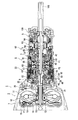
以下、図面に沿って、本発明の実施の形態について説明する。図1は、本発明に係る自動変速機の全体断面図、図2ないし図4は、その部分拡大断面図である。自動変速機1は、図1に示すように、トルクコンバータ2と、3個のプラネタリギヤ3、4、5を有する多段変速機構6と、を有しており、これらトルクコンバータ及び多段変速機構が1軸状に直列的に配置されていると共に、コンバータハウジング7及びミッションケース9からなる一体ケースに収納されている。
【0054】
トルクコンバータ2は、図2に詳示するように、エンジン出力軸(図示せず)に連結されるカバー10に設けられたポンプぺラ11と、多段変速機構6の入力軸12に連結されるタービンランナ13と、ワンウェイクラッチ15を介して支持されているステータ16と、を有しており、更に上記カバー10と入力軸12をスプリングダンパ17を介して機械的に連結するロックアップクラッチ19を備えている。また、コンバータハウジング7及びミッションケース9の間部分にはポンプケース20が固定されており、該ケース20には、オイルポンプ21が配設されていると共に、前記カバー10が回転自在に支持されている。更に、該ケース20の後側面にはポンプカバー22が固定されており、該カバー22には前記ワンウェイクラッチ15のインナレースが固定されていると共に、各油路が形成されている。
【0055】
前記多段変速機構6の前方部分(トルクコンバータ側)は、3個のクラッチC1、C2、C3がその油圧アクチュエータと共にまとめて配置されるクラッチ部23となっている。該クラッチ部は、図3に詳示するように、前記ポンプカバー22のボス部22aに回転自在に支持されると共に前記入力軸(入力部材)12に連結されているスリーブ25を有している。該スリーブ25は前方部分にてフランジ状になっており、かつ該フランジ部25aの外周部分に第3ドラム部材(クラッチドラム)26が固着されている。該第3ドラム部材の内周面にはスプライン26aが形成されており、該スプラインに、第3クラッチC3のドライブプレート(外摩擦板)27が係合していると共に、第2ドラム部材(クラッチドラム)29が係合しており、両クラッチドラム(第3ドラム部材、第2ドラム部材)26,27は、一体に回転して共通化されている。
【0056】
該第2ドラム部材29はその内径側に可動部材30が一体に固着されて、前記スリーブ25に油蜜状に軸方向移動自在に支持されており、かつそのドラム部外周面にスプライン29aが形成されて前記第3ドラムのスプライン26aに係合していると共に、その内周面にスプライン29bが形成されて、該スプラインに第2クラッチC2のドライブプレート(外摩擦板)31が係合している。また、前記第2及び第3クラッチC2、C3の内径側において、前記入力軸12に固定されて第1ドラム部材(クラッチドラム)32が配置されており、該ドラム部材の外径側部内周面にスプライン32aが形成されており、該スプラインに、第1クラッチC1のドライブプレート(外摩擦板)33が係合している。
【0057】
一方、異なる半径上に、小径側から第1ハブ35、第2ハブ36、第3ハブ37が順次配設されており、各ハブの外周面にはそれぞれスプライン35a、36a、37aが形成されている。そして、第1ハブのスプライン35aには第1クラッチC1のドリブンディスク(内摩擦板)39が、第2ハブのスプライン36aには第2クラッチC2のドリブンディスク(内摩擦板)40が、第3ハブのスプライン37aには第3クラッチC3のドリブンプレート(内摩擦板)41がそれぞれ係合しており、また第1ハブ35は中心軸からなる中間軸42に、第2ハブ36は該中心軸に被嵌する第2スリーブ軸43に、第3ハブ37は該第2スリーブ軸に被嵌する第3スリーブ軸45にそれぞれ連結・固定されている。即ち、中間軸42、第2スリーブ軸43及び第3スリーブ軸45は同軸状にそれぞれブッシュ等を介在して回転自在に支持されている。
【0058】
また、前記スリーブのフランジ部25aには、その軸方向後側にて、前記可動部材30が油蜜状に嵌合して、第3クラッチ用油圧アクチュエータ46を構成しており、上記可動部材30に固定されている第2ドラム部材29は、前記第2クラッチC2の係合面を越えた先端部29dが前記第3クラッチC3に対向して、第3クラッチ用ピストンの一部を構成している。前記可動部材30には、その軸方向後側にて、第2ピストン部材47が油密状に嵌合して、第2クラッチ用油圧アクチュエータ49を構成しており、該ピストン部材の外径側先端部47aが前記第2クラッチC2に対向している。更に、第2ピストン部材47の背面(軸方向後側)には、スリーブ25に嵌合されたスナップリングにより軸方向移動が規制されてキャンセルプレート50が油密状に嵌合しており、該キャンセルプレート50と第2ピストン部材47の背面との間はリターンスプリング51が縮設されていると共に、前記油圧アクチュエータ46,49の遠心油圧をキャンセルするキャンセル室52となっている。
【0059】
また、前記第1ドラム部材32は、前記キャンセルプレート50の軸方向後側に配置されており、該第1ドラム部材には、その軸方向後側にて、第1ピストン部材53が油密状に嵌合して、第1クラッチ用油圧アクチュエータ55を構成しており、該ピストン部材の先端53aが第1クラッチC1に対向している。更に、第1ピストン部材53の背面(軸方向後側)には、入力軸12に嵌合されたスナップリングにより軸方向移動が規制されてキャンセルプレート56が油密状に嵌合しており、該キャンセルプレートと第1ピストン部材53の背面との間はリターンスプリング57が縮設されていると共に、前記油圧アクチュエータ55の遠心油圧をキャンセルするキャンセル室59となっている。
【0060】
即ち、第3ドラム部材26及び第2ドラム部材29は、スプライン26a、29bが形成されている外周部分が直線状に延びており、かつ第3ドラム部材26は、第2ドラム部材29の外周面を被嵌して軸方向に、該第2ドラム部材より所定最延長して延設されている。従って、これら第3ドラム部材26及び第2ドラム部材29に係合している第3クラッチC3及び第2クラッチC2が軸方向に略々整列して、かつ第3クラッチC3が、そのドライブプレートの外周面を第2クラッチのそれよりも略々第2ドラム部材26の板厚だけ外径側に位置すると共に軸方向後側に配置されている。
【0061】
また、第1クラッチC1は、第2及び第3クラッチの内径側に位置されており、かつ該第1クラッチの内径側に、前記第1クラッチ用油圧アクチュエータ55のキャンセル室59の大部分が配置されており、該第1クラッチC1は、第2及び第3クラッチC2,C3の内周側に配置されて、これら第2及び第3クラッチとは独立して作動する。
【0062】
前記多段変速機構6の後方部分は3個のプラネタリギヤ3、4、5がその係止手段(ブレーキ及びワンウェイクラッチ)とまとめて配置されるギヤ部60となっている。該ギヤ部60は、図4に詳示するように、前方(入力部材12側)から、前記第3スリーブ軸45に形成されたサンギヤS1を有する第1プラネタリギヤ3、前記第2スリーブ軸43にスプライン連結されるキャリヤCR2を有する第2プラネタリギヤ4、そして前記中間軸42に形成されたサンギヤS3(サンギヤS2をスプライン固定)を有する第3プラネタリギヤ5が順次配設されている。更に、前記クラッチ部23と第1プラネタリギヤ3との軸方向間部分に第3ブレーキ(第4のブレーキ)B3、第1ワンウェイクラッチ(第3のワンウェイクラッチ)F1及び第2ワンウェイクラッチ(第2のワンウェイクラッチ)F2(係止手段)が配設されており、また第2プラネタリギヤ4と第3プラネタリギヤ5との軸方向間部分に第3ワンウェイクラッチ(第1のワンウェイクラッチ)F3が配設されている。
【0063】
第3ブレーキB3は多板ブレーキからなり、複数枚の外ブレーキプレート61がケース9に形成されたスプライン9aに係合しており、また第2ワンウェイクラッチF2のアウタレース62に固定されているハブ63に、上記ブレーキの内ブレーキディスク65が係合している。前記第2ワンウェイクラッチF2のインナレースは前記第3のスリーブ軸45自体で形成されており、前記第3ブレーキB3と第2ワンウェイクラッチF2とは、異なる径方向位置において、軸方向に略々オーバラップする位置に配置されている。
【0064】
前記第3ブレーキB3の軸方向後方側には、該ブレーキ用油圧アクチュエータ66が配設されており、該アクチュエータは、ケース9に固定されたシリンダ部材67と、該シリンダ部材に油密状に嵌合して、その前方端部69aが上記ブレーキB3に対向しているピストン部材69と、からなる。上記シリンダ部材67は、環状の油室を有するように外壁、内壁及び底壁からなる環状形状からなり、かつその内壁及び底壁の一部は、キャリヤCR1を構成するカップ状部材80(後述)と干渉しないように斜めになっており、前記外壁に形成されたスプラインがケース9のスプライン9aに係合して回転方向移動不能に、またスプライン段部とスナップリング74により軸方向移動不能にケース9に連結されている。更に、上記シリンダ部材の内周面にスプライン係合されて、第1ワンウェイクラッチF1のアウタレース70が配置されており、該ワンウェイクラッチのインナレース71は第1プラネタリギヤ3におけるキャリヤCR1のボス部72にスプライン係合している。そして、上記第3ブレーキ用油圧アクチュエータ66と第1ワンウェイクラッチF1は、異なる径方向位置において、軸方向に略々(少なくとも一部を)オーバラップ位置に配置されている。なお、上記ピストン部材69の先端部分はクシ歯状に形成され、該クシ歯の間部分にリターンスプリング73が配置されている。従って、第2ワンウェイクラッチF2及び第1ワンウェイクラッチF1は軸方向に並んで配置されており、かつ第3ブレーキB4及びその油圧アクチュエータ66が外径側にあって、上記ワンウェイクラッチF1、F2に軸方向に略々オーバラップするように配置されている。
【0065】
第1プラネタリギヤ3は、サンギヤS1に噛合するピニオンP1aとリングギヤR1に噛合するピニオンP1bとを有するデュアルプラネタリギヤからなり(図5参照)、上記互に噛合するピニオンP1a、P1b支持するをキャリヤCR1がそのボス部72により第3スリーブ軸45に回転自在に支持されており、またサンギヤS1が第3スリーブ軸45に一体に形成されている。更に、リングギヤR1が、その後方端でスプライン結合されているプレート75により軸方向を規制されて回転自在に支持されていると共に、第2プラネタリギヤ4のリングギヤR2にスプライン結合されている。
【0066】
そして、第1ブレーキ(第1のブレーキ)B1は多板ブレーキからなり、その複数枚の外ブレーキプレート76が、ケース9に形成されたスプライン9b(前記スプライン9aに連続して形成)に係合されると共に該外ブレーキプレート76の前方部は前記第3ブレーキ用シリンダ部材67の底壁に当接しており、前方方向移動を前記第3ブレーキ用シリンダ部材67と共にスナップリング74にて規制されて支持されている。これにより、スナップリング74が、第3ブレーキ用シリンダ部材67用と第1ブレーキB1用とに兼用される。前記第1ブレーキ用の内ブレーキディスク79は、前記キャリヤCR1を構成するカップ状部材80の外径側外周面に形成されたスプラインに係合している。該カップ状部材80は、その外径側平坦面80aが前記第1プラネタリギヤ3の外径側を覆うように延びており、該平坦面80a、即ち該平坦面に形成されたスプライン係合している第1ブレーキB1が、第1プラネタリギヤ3の外径側にて軸方向に略々オーバラップするように(正確にはプラネタリギヤ3の幅内に第1ブレーキB1が納まるように)配置されている。
【0067】
上記第1ブレーキB1の後方側には該ブレーキ用の油圧アクチュエータ81が配設されている。該アクチュエータ81は、前記ミッションケース9の段付小径部9cに固定・配置されているシリンダ部材82及びそれに油密状に嵌合しているピストン部材83を有しており、該アクチュエータ81は、前記第1及び第2プラネタリギヤ3、4の外径側にて、軸方向において股がって、配置されている。即ち、第1プラネタリギヤ3の外径側において、該第1プラネタリギヤの所定要素(CR1)を係止する第1ブレーキB1及びその油圧アクチュエータ81が、該第1プラネタリギヤと軸方向に少なくとも一部がオーバラップするように配置されている。なお、上記ピストン部材83はクシ歯状に第1ブレーキB1に向けて延びており、かつ該クシ歯の間にリターンスプリング85が配置されている。また、前記シリンダ部材82は、環状形状からなり、その外壁がケース9のスプライン9dの先端(前方端)部に当接してその後方向移動を規制されていると共に、ピストン部材83のリターンスプリング85を介してスプリングリテーナにてその前方向移動を規制されており、該シリンダ部材82をケース9に固定するための専用の固定手段が不要となっている。
【0068】
第2プラネタリギヤ4は、シンプルプラネタリギヤからなり、ピニオンP2を支持するキャリヤCR2が第2スリーブ軸43にスプライン係合している。また、サンギヤS2が、前記中間軸42にスプラインにより一体に結合されており、またリングギヤR2が前記第1プラネタリギヤのリングギヤR1にスプラインにより一体に結合されている。該第2プラネタリギヤ4は、デュアルプラネタリギヤからなる第1プラネタリギヤ3より小径にて構成されており、従ってリングギヤR2の前方端に外径方向に延びる鍔部86が形成されて、該鍔部の外周部が前記リングギヤR1の内周面に前記プレート75と共にスプラインにより一体に連結されている。前記第1ブレーキB1用油圧アクチュエータ81は、そのピストン延出部を除いて、上記小径からなる第2プラネタリギヤ4の外径側に第2ブレーキB2と共に配置されている。従って、該油圧アクチュエータ81は、ケース9が段差9cにより小径となっているにも拘らず、所定の受圧面積が確保され、該第1ブレーキB1の必要トルクに対応するトルク容量を有する。
【0069】
そして、前記第1ブレーキB1用油圧アクチュエータ81の後方側に第2ブレーキ(第2のブレーキ)B2が配置されている。該第2ブレーキB2は多板ブレーキからなり、複数枚の外ブレーキプレート87が前記小径部となるケース9の内スプライン9dに係合しており、内ブレーキディスク89が前記リングギヤR2の外周面に形成されたスプラインに係合している。該第2ブレーキB2は、第2プラネタリギヤ4の外径側において、該プラネタリギヤと軸方向にオーバラップするように(正確にはプラネタリギヤ4の幅内にブレーキB2が納まるように)配置されている。
【0070】
該第2ブレーキB2の後方側には該ブレーキ用の油圧アクチュエータ90が配設されている。該アクチュエータ90は、ケース9の内周面に固定・配置されているシリンダ部材91及びそれに油蜜状に嵌合しているピストン部材92を有しており、該ピストン部材は、他のもの69、83がブレーキに向けて延びかつクシ歯の間にリターンスプリング73、85を配置する延出部を有するのに対し、該延出部を有さない短い構造からなる。該油圧アクチュエータ90は、第2ブレーキB2の外径側において、第2プラネタリギヤ4の後端部に一部オーバラップするか、又はそのピストン部材92先端部が略々整列するように配置されている。そして、前記第2ブレーキB2の外及び内ブレーキプレート(ディスク)87、89は、その外径部分に所定間隔毎に切欠かれており、該切欠き部93に、前記ピストン部材92の先端部に設けられた支持プレート95とケース等の固定部材との間に縮設されたリターンスプリング96が配置されている。また、上記シリンダ部91は、環状部材からなると共に、後述する第3ワンウェイクラッチF3のアウタレース100の凹部100aに合せてその内壁及び底壁の一部が斜めになっており、かつその後方端を上記アウタレースに当接して後方向移動が規制され、また前方向移動がピストン部材92、支持プレート95及びリターンスプリング96を介して規制され、専用の固定手段が不要となっている。
【0071】
前記第2ブレーキB2用油圧アクチュエータ90の後方側、即ち第2プラネタリギヤ4と第3プラネタリギヤ5との間部分には、第3ワンウェイクラッチ(第1のワンウェイクラッチ)F3が配設されている。第2プラネタリギヤ4の後キャリヤプレート97と、第3プラネタリギヤ5のリングギヤR3とは連結部材99を介して連結されている。上記ワンウェイクラッチF3は、固定側となるアウタレース100と可動側となるインナレース101とを有しており、アウタレース100の外周面がケース9にスプライン係合されていると共に、インナレース101の内周面が上記連結部材99のボス部99aにスプライン係合している。
【0072】
上記アウタレース100は、ローラ又はスプラグ等の係合部材102部分が該係合部分の幅に合せて幅広になっていると共に、外径方向に向ってその前後両方から漸減するように幅狭となっており、かつ外径端にあっては後方側のみ鍔状に延出している。これにより、該アウタレース100は、比較的軸方向に長い係合部材102に合せた接合面を有すると共に、ケース9との係合部分も上記鍔状の延出部により所定軸方向長さを確保して、所定トルク容量を備えるものでありながら、その前方側が凹んで凹部100aとなっており、該凹部に、前記第2ブレーキ用油圧アクチュエータ90の後方部分が収納されて、該油圧アクチュエータ90を含む第2ブレーキ装置の第2プラネタリギヤ4の外径側配置(少なくとも一部が軸方向にオーバラップする)を可能として、自動変速機の軸方向の短縮化に寄与している。即ち、上記油圧アクチュエータ90は、第2プラネタリギヤ4及び第3ワンウェイクラッチF3の間部分に配置されて、コンパクトな構成となっている。また、該アウタレース100は、スナップリング94及びケース9の段付き部により軸方向移動が規制されて、上記スプライン係合と相俟って、ケース9に固定されている。
【0073】
前記インナレース101は、係合部材102部分が該係合部材に合せて幅広になっており、かつその内径側に向けて漸減するように幅狭になって、上述と同様に、接合面積に起因するトルク容量を確保すると共に、連結部材99と該キャリヤプレート97とのスプライン連結スペースを確保している。
【0074】
前記第3ワンウェイクラッチF3の後方側には第3プラネタリギヤ5が配設されている。該第3プラネタリギヤはシンプルプラネタリギヤからなり、リングギヤR3が前記連結部材99のフランジ99b外周面に係合して前記キャリヤCR2と連結している。一方、サンギヤS3は、前記中間軸42の後方端部にあって該軸に一体形成されており、またピニオンP3を支持するキャリヤCR3は出力軸105に一体に形成されている。中間軸42は前記サンギヤS3部分を最も大径として、前方に向かって順次小径となる段付き構造からなる。出力軸105は上記キャリヤCR3が鍔状に拡がって形成されており、前記中間軸42の後端突出部42aと出力軸105の前端中空部105aとが嵌合して回転自在にかつ軸方向移動不能に支持されている。なお、中間軸42は、その前端部を入力軸12に嵌合して回転自在に支持されて、その両端部をそれぞれ入力軸12及び出力軸105を介してケースに間接支持されている。また、出力軸105は、その前端部がケース9の後側9eの鍔部9fにベアリングを介して直接支持されると共に、その後部分が図示しないエクステンションケース(ミッションケース9の後端部に固定;図示せず)にベアリングを介して直接支持されている。
【0075】
前記第3ワンウェイクラッチF3の後方側に第4ブレーキ(第3のブレーキ)B4が配設されている。該第4ブレーキは多板ブレーキからなり、多数板の外ブレーキプレート106が前記アウタレース100と共にケース内周面のスプライン9dに係合していると共に、スナップリングにより軸方向移動が規制されて支持されており、また内ブレーキディスク107がリングギヤR3の外周面に形成されたスプラインに係合している。該第4ブレーキB4は、第3プラネタリギヤ5の外径側において、該プラネタリギヤ5に軸方向に略々オーバラップして(少なくとも一部がオーバラップして)配置されている。
【0076】
上記第4ブレーキB4及び第3プラネタリギヤ5の後方側に上記ブレーキB4用の油圧アクチュエータ109が配設されている。該油圧アクチュエータはケース9の後端部内周面、後側面9e及び鍔部9fをシリンダとしたダブルピストンタイプからなり、第1ピストン部材110、中間支持部材111及び第2ピストン部材112を有する。第1ピストン部材110は、上記シリンダに油密状に嵌合していると共に、その外径側にて前方に突出する延出部110a及びその内径側にて後方に突出するハブ部110bを有しており、延出部110aがケーススプライン9dに係合しつつ上記第4ブレーキB4に対向している。
【0077】
中間支持部材111は、その内径側を上記ハブ部110bに嵌合してシリンダに油密状に嵌合していると共に、その外径側延出部がケースの後側面9eに当接している。第2ピストン112は、その外径側を該支持部材延出部の内周面に接してシリンダに油密状に嵌合しており、かつその内径部分にて前記第1ピストン110のハブ部110bに当接している。なお、第1ピストン110とケース鍔部9eに設けられた支持プレートとの間にリターンスプリング113が縮設されている。
【0078】
従って、上記第4ブレーキB4用油圧アクチュエータ109は、ケース後端面を利用した大きい受圧面積からなると共に、第1及び第2のピストン部材110、112からなるダブルピストンに基づき更に大きな受圧面積が得られ、上記ブレーキB4の設定トルク容量に対応する大きな押圧力が得られる。なお、上記キャリヤCR3の外径側にパーキングギヤ115が一体に設けられており、該パーキングギヤを、ケース9に貫通して設けられたパーキングポール116により係止することにより出力軸105が固定される。また、上記油圧アクチュエータ109の第1ピストン110は、上記パーキングギヤ115を被嵌すると共に、上記パーキングポール116部のみを切欠いており、また第3プラネタリギヤ5の外径側において、僅かに軸方向にオーバラップして後方側に配置されている。
【0079】
ついで、図5の上記自動変速機構のスケルトン図、図6の作動表及び図7の速度線図に沿って、上述した自動変速機構6の作用について説明する。
【0080】
該自動変速機構6は、第1プラネタリギヤ3からなるフロントギヤユニット130と、第2プラネタリギヤ4及び第3プラネタリギヤ5からなるリヤギヤユニット131とにその機能上分かれており、かつリヤギヤユニット131は、中間軸42を介して連結されている両サンギヤS2、S3からなる第3回転要素137と、連結部材99を介して連結されているキャリヤCR2及びリングギヤR3からなる第2回転要素136と、互に連結されているリングギヤR1及びR2からなる第1回転要素135と、出力軸105に連結されているキャリヤCR3からなる(出力用)回転要素138の、合計4個の回転要素から構成される。
【0081】
1速では、図6に示すように、第1クラッチC1が係合し、第3ワンウェイクラッチF3が作動し、入力軸12とサンギヤS2、S3(第3回転要素137)が連結されると共に、キャリヤCR2及びリングギヤR3(第2回転要素)の逆転がワンウェイクラッチF3により阻止されて、入力軸12の回転(RIN)は、クラッチC1を介して直接第3プラネタリギヤ5のサンギヤS3に入力される。すると、第3ワンウェイクラッチF3の作動に基づき停止状態にあるリングギヤR3により、図7の速度線図において、線図L1に示す状態となり、出力軸105が接続されたキャリヤCR3からは、正回転の1速1STが取り出される。なお、第2プラネタリギヤは、サンギヤS2が回転するが、空転状態となっている。
【0082】
この際、1速状態及び発進時に基づく大きなトルクが作用し、該トルクを第3ワンウェイクラッチF3にて担持することになるが、該第3ワンウェイクラッチF3は、第2及び第3プラネタリギヤ4、5の間部分にて軸方向に比較的長い空間に配置され、特にその係止部材(ローラ又はスプラグ)102及びそれに接するアウタレース100及びインナレース101部分の面積も広くなっており、上記大きなトルクを確実に担持し得る。
【0083】
2速では、図6に示すように、1速時の第1クラッチC1の係合に加えて、第3ブレーキB3が係合すると共に、第3ワンウェイクラッチF3の作動が解除され、第1及び第2ワンウェイクラッチF1、F2が作動する。この状態では、第1プラネタリギヤ3は、ロック状態の第1ワンウェイクラッチF1により停止状態のキャリヤCR1、及び第3ブレーキB3の係止によりロック状態の第2ワンウェイクラッチF2により停止状態のサンギヤS1に基づき、停止状態にあり、従ってそのリングギヤR1に連結している第2プラネタリギヤ4のリングギヤR2も停止状態にある。
【0084】
そして、入力軸12の回転は、第1クラッチC1を介してサンギヤS2から第2プラネタリギヤ4に入力されると共に、サンギヤS3を介して第3プラネタリギヤ5に入力される。第2プラネタリギヤ4は、前述したようにリングギヤR2の回転が阻止され(速度=0)、図7の速度線図において、線図L2に示す状態となり、出力軸105が接続されたキャリヤCR3から、正回転の2速回転(2ND)が取り出される。
【0085】
この際の、リングギヤR2の回転トルクは、第1ワンウェイクラッチF1及び第2ワンウェイクラッチF2を介して第3ブレーキB3により分担されて担持され、第1ワンウェイクラッチF1のトルク担持能力を利用する形でその分第2ワンウェイクラッチF2及び第3ブレーキB3のトルク負担能力を小さなものとすることができ、第2ワンウェイクラッチF2及び第3ブレーキB3の小容量化及び小型化が図れる。これにより、第3ブレーキB3及びその油圧アクチュエータ66、並びに第1及び第2ワンウェイクラッチF1、F2を、第1プラネタリギヤ3の前方部分にまとめてコンパクトに配置することが可能となる。
【0086】
3速では、図6に示すように、1、2速時の第1クラッチC1の係合に加えて、第3クラッチC3が係合されると共に、第2ワンウェイクラッチF2の作動が解除され、第1ワンウェイクラッチF1の作動が維持される。この状態では、入力軸12の回転は、それまでの第1クラッチC1を介したリヤギヤユニット131への入力に加えて、第3クラッチC3を介してフロントギヤユニット130のサンギヤS1にも入力され、かつキャリヤCR1が第1ワンウェイクラッチF1により係止される。
【0087】
すると、第1プラネタリギヤ3は、サンギヤS1に入力軸12の回転が入力され、キャリヤCR1が係止されることから、図7の速度線図において、線図L3に示す状態となり、フロントギヤユニット130の出力要素としてのリングギヤR1から、正回転RV1がリヤギヤユニット131の入力要素としての第2プラネタリギヤ4のリングギヤR2に出力される。一方、リヤギヤユニット131には、サンギヤS2、S3に入力軸12の回転RINが入力されているので、上記リングギヤR2へ入力される回転RV1は、図7の線図L4に示すように、合成され、出力軸105に連結されるキャリヤCR3からは、3速回転(3RD)が取り出される。なお、第3ブレーキB3は、係合状態となっているが、第2ワンウェイクラッチF2が空転状態なので、該ブレーキB3は変速に何ら関与しない。
【0088】
この際、第1ワンウェイクラッチF1が、第1プラネタリギヤ3へ伝達されるトルクの反力を担持するが、3速状態にあっては、該フロントギヤユニット130である第1プラネタリギヤ3を経由するトルクと、リヤギヤユニット131に第1クラッチC1を介して直接伝達されるトルクとが合成されるため、上記第1ワンウェイクラッチF1が担持する反力トルクは、伝達トルク全体の一部で足りる。従って、該第1ワンウェイクラッチF1は、トルク容量が小さい小型のもので足り、第1プラネタリギヤ3前方の比較的狭いスペースに、他の係止手段B3、F2と共にまとめて配置することが可能となる。
【0089】
4速では、図6に示すように、1、2、3速時の第1クラッチC1の係合に加えて、第2クラッチC2が係合されると共に、第1ワンウェイクラッチF1の作動が解除される。この状態では、入力軸12の回転は、それまでの第1クラッチC1を介したリヤギヤユニット131のサンギヤS2、S3への入力に加えて、第2クラッチC2を介してキャリヤCR2及びリングギヤR3にも入力され、該リヤギヤユニット131、即ち第2及び第3プラネタリギヤ4、5全体が直結回転となり、図7の線図L5に示す状態となり、出力軸105に連結されるキャリヤCR3から、4速回転(4TH)が取り出される。
【0090】
この際、第3クラッチC3及び第3ブレーキB3は、図6に示すように、係合状態となっているが、第1プラネタリギヤ3は、サンギヤS1に第2クラッチC2を介して入力軸12の回転が伝達される一方で、第2プラネタリギヤ4が、入力軸12と直結状態で正回転することから、そのリングギヤR2に連結されたリングギヤR1にも入力軸12の回転が入力され、図7の線図L6の状態となり、フロントギヤユニット130を構成する第1プラネタリギヤ3は全体が直結状態で空転する。また、該4速状態は、フロントギヤユニット130及びリヤギヤユニット131は、共に直結状態であって、ブレーキ及びワンウェイクラッチの係止手段はなにも作動せず、反力を担持することはない。
【0091】
5速では、図6に示すように、第1クラッチC1の係合が解除されると共に、第2及び第3クラッチC2、C3がそのまま係合状態を維持され、かつ第1ブレーキB1が係合される。この状態では、入力軸12の回転は、第2クラッチC2を介してリヤギヤユニット131である第2プラネタリギヤ4のキャリヤCR2及び第3プラネタリギヤ5のリングギヤR3に入力されると共に、第3クラッチC3を介してフロントギヤユニット130である第1プラネタリギヤ3のサンギヤS1に入力される。すると、キャリヤCR1が第1ブレーキB1により係止されているので、フロントギヤユニット130は、図7線の図L3で示す状態となり、リングギヤR1からは、減速された正回転RV1がリヤギヤユニット131のリングギヤR2に出力される。一方、前述したように、該リヤギヤユニット131のキャリヤCR2及びリングギヤR3には、入力軸12の回転が入力されるので、速度線図は、図7の線図L7となり、キャリヤCR3から出力軸105へ、5速回転(5TH)が取り出される。この際、第3ブレーキB3は、図6に示すように、係合状態となっているが、第2ワンウェイクラッチF2が空転状態となっているので、該ブレーキB3は何ら変速に関与しない。
【0092】
また、該5速状態にあっては、第1ブレーキB1が上記伝達トルクの反力を担持するが、高速状態である5速にあっては、そのトルク容量は小さくて足り、更に、第2クラッチC2を経由する経路と、第3クラッチC3を経由する経路からのトルクが、リヤギヤユニット131で合成されて出力軸105に伝達されるので、キャリヤCR1及びリングギヤR1を係止する上記第1ブレーキB1のトルク容量は、伝達トルク全体の一部で足り、更にそのトルク容量は小さなもので足りる。従って、該第1ブレーキB1は、第1プラネタリギヤ3の外径側にて軸方向に比較的短い長さに設置でき、かつその油圧アクチュエータ81も、隣接する第1及び第2プラネタリギヤ3、4に股がる外径側における、軸方向に比較的短い小さなスペースに設置することができ、上記第3ブレーキB3及びその油圧アクチュエータ81を、第1プラネタリギヤ3の外径側における比較的小さなスペースに設置することが可能となる。
【0093】
後進では、図6に示すように、第3クラッチC3が係合されると共に、第4ブレーキB4及び第1ワンウェイクラッチF1が係止される。この状態では、入力軸12の回転は、第3クラッチC3を介してフロントギヤユニット130のサンギヤS1に入力され、キャリヤCR1が第1ワンウェイクラッチF1により係止されることから、速度線図は、図7の線図L3に示す状態となり、リングギヤR1からは、正回転の出力回転RV1がリヤギヤユニット131のリングギヤR2に出力される。該リヤギヤユニット131は、リングギヤR3及びキャリヤCR2が第4ブレーキB4により係止されるので、図7の線図L10で示す状態となり、キャリヤCR3から出力軸105へ、後進回転(REV)が取り出される。
【0094】
この際、該後進状態は、減速された大きなトルクが上記リングギヤR3及びキャリヤCR2を係止する第4ブレーキB4に作用するが、該第4ブレーキB4は、第3プラネタリギヤ5の外径側にて該ギヤに略々オーバラップする比較的軸方向に長いものからなり、かつその油圧アクチュエータ109は、ケース9の後端面9eに配置された比較的広い受圧面積からなると共にダブルピストン構造からなり、大きな押圧力を作用することができ、上記大きな反力に対応する要求トルクを確実に担持することが可能となる。
【0095】
また、エンジンブレーキ(コースト)時には、図6に示すように、通常の作動に加えて、3速及び後進時には、第1ブレーキB1が係合され、第1ワンウェイクラッチF1の空転に対してキャリヤCR1を確実に係止し、2速時には第2ブレーキB2が係合され、リングギヤR2を確実に係止し、更に1速時には、第1ブレーキB4が係合されて、リングギヤR3が確実に係止される。
【0096】
更に、2速のエンジンブレーキ時に、本来のエンジンブレーキ用の第2ブレーキB2に加えて第1ブレーキB1を作動させて、リングギヤR2の係止を、直接作動する第2ブレーキB2及びキャリヤCR1を介して作動する第1ブレーキB1により共に行わせ、第2ブレーキB2のトルク容量を小さくしてその分該ブレーキB2を小型化することも可能である。第2ブレーキB2は、上記2速時のエンジンブレーキ用であって、そのトルク容量は小さくて足り、第2プラネタリギヤ4の外径部分の比較的小さな設置スペースで足りるが、更に上述したように、該2速エンジンブレーキ時に、第1ブレーキB1を共働作動すると、更に第2ブレーキB2のトルク容量が小さくて足り、その油圧アクチュエータ90も含めて小さな設置スペースに配置したものでありながら、確実で信頼性の高いブレーキ作動を行うことができる。
【0097】
更に、上述したように、第2プラネタリギヤ4に入力軸からのトルクが入力する場合、2速時にサンギヤS2、S3から、3速時にサンギヤS1、S2、S3から、4速時にサンギヤS2、S3から、そして5速時に、サンギヤS1、S2及びリングギヤR3から、それぞれ入力トルクがフロントギヤ部130及びリヤギヤ部131に入力される。従って、入力トルクが第2プラネタリギヤ4のみに入力されることはなく、該第2プラネタリギヤ4は、最適なギヤ比を得るために小型化されると共に、上記分散入力に基づく強度上からも小型化が可能となり、該小径のプラネタリギヤ4の外径側に、油圧アクチュエータ81を配置して、第1ブレーキB1の必要トルクを担持し得るトルク容量を有するものでありながら、軸方向及び径方向のコンパクト化を可能とする。
【0098】
また、第1、第2及び第3プラネタリギヤ3、4、5の外径側に各ブレーキB1、B2、B4を配置しても、径方向寸法が大きくなることはない。蓋し、上記配置構造により、ブレーキ用としての軸方向スペースが不要となり、軸方向寸法が短縮されるため、各プラネタリギヤの軸方向寸法に余裕ができ、ギヤのトルク容量を稼ぐことが可能となると共に、各ブレーキのプレート枚数を増加することで、径方向寸法を大きくすることなく、ブレーキのトルク容量も確保でき、この結果、総合的にコンパクトに設計することが可能となる。
【0099】
また、入力トルクを各プラネタリギヤ3、4、5に伝達する各クラッチC1、C2、C3は、トルク容量を充分に確保するために径方向寸法を大きくすることが好ましいが、各クラッチ部23は、多段変速機構6のトルクコンバータ2側に配置されるので、径方向寸法の大きなものから、出力軸に向けて小径化して配置することができ、FR用の自動変速機として車輌搭載上好ましい全体形状の変速機を得ることができる。
【0100】
なお、上記実施の形態は、上述自動変速機構6に沿って説明したが、自動変速機構はこれに限らず、3個のプラネタリギヤ(シンプルでもデュアルでも可)を有し、かつ少なくとも3個のブレーキ及び1個のワンウェイクラッチを有するものならば、本発明の適用が可能である。
【図面の簡単な説明】
【図1】本発明に係る自動変速機の全体を示す断面図。
【図2】そのトルクコンバータ部分を示す拡大断面図。
【図3】その多段変速機構の前部であるクラッチ部を示す拡大断面図。
【図4】その多段変速機構の後部であるギヤ部を示す拡大断面図。
【図5】多段変速機構のスケルトン図。
【図6】その作動を示す図。
【図7】その速度線図。
【符号の説明】
1 自動変速機
2 トルクコンバータ
3 第1プラネタリギヤ
4 第2プラネタリギヤ
5 第3プラネタリギヤ
6 多段変速機構
9 ミッションケース
12 入力部材(入力軸)
42 第1の入力要素(中間軸)
43 第2の入力要素(第1スリーブ軸)
45 第3の入力要素(第2スリーブ軸)
66 (B3用)油圧アクチュエータ
81 (B1用)油圧アクチュエータ
90 (B2用)油圧アクチュエータ
99 連結部材
100 (F3の)アウタレース
100a 凹部
101 (F3の)インナレース
102 (F3の)係止部材
105 出力部材(出力軸)
109 (B4用)油圧アクチュエータ
130 フロントギヤユニット
131 リヤギヤユニット
135 第1回転要素
136 第2回転要素
137 第3回転要素
138 出力回転要素
B1 第1の(第1)ブレーキ
B2 第2の(第2)ブレーキ
B3 第4の(第3)ブレーキ
B4 第3の(第4)ブレーキ
C1 第1クラッチ
C2 第2クラッチ
C3 第3クラッチ
F1 第3の(第1)ワンウェイクラッチ
F2 第2の(第2)ワンウェイクラッチ
F3 第1の(第3)ワンウェイクラッチ[0001]
BACKGROUND OF THE INVENTION
The present invention relates to an automatic transmission mounted on an automobile, and is particularly suitable for use in a multi-stage automatic transmission such as a 5-speed forward mounted on an FR (front engine / rear wheel drive) automobile, and more specifically, a planetary gear. And an arrangement structure such as a brake.
[0002]
[Prior art]
Conventionally, as shown in Japanese Patent Laid-Open No. 5-33836, all three planetary gears are integrated on an intermediate shaft, and by supporting the intermediate shaft with an input / output shaft, the center support is eliminated and the axial dimension is compact. An automatic transmission structure has been devised that achieves improved transmission and gear noise characteristics.
[0003]
In this automatic transmission, the ring gears of the three planetary gears are connected to the brakes, respectively, but the first planetary gear on the torque converter side (front) covers the clutches C1 and C2 from the ring gear. The first band brake is applied to the brake drum extending to the second planetary gear, and the second planetary gear has a second multi-plate brake disposed on the outer diameter side of the first planetary gear, and its hydraulic servo is connected to the outer diameter of the second planetary gear. Further, the third planetary gear has a third multi-plate brake disposed on the outer diameter side of the third planetary gear, and a hydraulic servo disposed on the output shaft support wall of the rear case. .
[0004]
[Problems to be solved by the invention]
Since the above automatic transmission has three planetary gears arranged adjacent to each other in series, it is difficult to arrange each brake along with its hydraulic servo on the outer diameter side of each planetary gear. For this reason, the first brake of the first planetary gear has to be provided with a brake drum extending forward, and a band brake has to be used due to dimensional constraints in the radial direction.
[0005]
For this reason, the conventional automatic transmission requires a large brake drum that covers the clutches C1 and C2, the structure is complicated, the assembly efficiency is lowered, and the compactness is not sufficient. Because of the use of a band brake, the degree of freedom of the brake control means is low, which hinders the improvement of shift feeling.
[0006]
Accordingly, an object of the present invention is to provide an automatic transmission in which each brake is a multi-plate brake and can be disposed on the outer diameter side of each planetary gear, thereby solving the above-described problems. .
[0007]
[Means for Solving the Problems]
According to the first aspect of the present invention, the power transmission path of the gear portion (60) is changed by the clutch (C ...) and the brake (B ...) to rotate the input member (12) to a plurality of speed stages (for example, In an automatic transmission (1) comprising a multi-speed transmission mechanism (6) that is shifted to 5 forward speeds and 1 reverse speed and transmitted to an output member (105) and housed in a transmission case (9). ,
First, second and third planetary gears (3, 4, 5) in which the gear portion (60) is coaxially arranged sequentially from the input member (12) to the output member (105)Of 3Having planetary gears,
The ring gear (R1) of the first planetary gear (3) and the ring gear (R2) of the second planetary gear (4) are connected to form a first rotating element (135), and the carrier of the second planetary gear (4) (CR2) and the ring gear (R3) of the third planetary gear (5) are connected to form a second rotating element (136). Both sun gears of the second planetary gear (4) and the third planetary gear (5) ( S2, S3) are connected to form a third rotating element (137), the carrier (CR3) of the third planetary gear (5) is connected to the output member (105),
A second one-way clutch (F2) that operates at a predetermined speed (for example, second gear) and can stop the sun gear (S1) of the first planetary gear (3) and the carrier (CR1) of the first planetary gear (3) ) Is disposed, and a third one-way clutch (F1) is disposed.
The outer brake plates (76, 106) are arranged on the inner peripheral surfaces (9b, 9d) of the transmission case so as to overlap each outer diameter side of the first and third planetary gears (3, 5) in the axial direction. The transmission includes the first and third brakes (B1, B4) each formed of a latched multi-plate brake, and the mission so as to overlap the outer diameter side of the second planetary gear (4) in the axial direction. A second brake comprising a multi-plate brake locked to the inner peripheral surface (9d) of the case and connected to the first rotating element (135) for coasting the predetermined gear (for example, second gear) (B2) is arranged,
The first brake hydraulic actuator (81) is disposed so as to overlap in the axial direction on the outer diameter side of the second planetary gear (4).
It is in the automatic transmission characterized by this.
[0008]
The present invention according to claim 2The carrier (CR1) of the first planetary gear is connected to the first brake (B1), the first rotating element (135) is connected to the second brake (B2), and the second rotating element (136). ) Is connected to the transmission case (9) via the third brake (B4) and the first one-way clutch (F3), and the carrier (CR1) of the first planetary gear (3) is connected to the first The first planetary gear sun gear (S1) is connected to the brake (B1), and the outer brake plate (76) is a multi-plate brake comprising an inner peripheral surface (9a) of the transmission case (9). 4 is connected to the brake (B3) via the second one-way clutch (F2).
The automatic transmission according to
[0009]
The present invention according to
The automatic transmission according to
[0010]
The present invention according to claim 4 provides:The fourth brake (B3) and its hydraulic actuator (66) and the second and third one-way clutches (F2, F1) are arranged so as to overlap in the axial direction.
The automatic transmission according to
[0011]
The present invention according to
An automatic transmission according to any one of
[0012]
The present invention according to claim 6 provides:The hydraulic actuator (90) for the second brake (B2) is disposed between the second planetary gear (4) and the first one-way clutch (F3).
An automatic transmission according to any one of
[0013]
The present invention according to
An automatic transmission according to any one of
[0014]
The present invention according to claim 8 provides:The hydraulic actuator (109) for the third brake (B4) has a double piston structure (110, 111, 112).
An automatic transmission according to
[0015]
The present invention according to
An automatic transmission according to
[0016]
The present invention according to
An automatic transmission according to any one of
[0018]
Claim11The present invention comprises three input elements (42, 43, 45) arranged coaxially,
A first input element (42) on the center side of the third planetary gear (5)Sun gear(S3)
The second input element (43) fitted to the first input element is connected to the second planetary gear (4).Carrier(CR2)
A third input element (45) fitted to the second input element is connected to the first planetary gear (3).Sun gearConnected to (S1),
ClaimAny one of 1 to 10The automatic transmission is described.
[0019]
Claim12The present invention relates to,in frontThe first input element isOf the third planetary gear (5)An intermediate shaft (42) integrally formed with the sun gear (S3), and the intermediate shaft has a stepped structure in which the sun gear has the largest diameter and gradually decreases toward the input member (12).
Claim7The automatic transmission is described.
[0027]
Claim13The present invention relates to a plurality of clutches (C1, C2, C3) on the input member (12) side of the multi-stage transmission mechanism (6).ArrangeSet up,
Claim11 or 12The automatic transmission is described.
[0028]
Claim14According to the present invention, the plurality of clutches include a first clutch (C1) interposed between the input member (12) and the first input element (42), and the input member (12). A second clutch (C2) interposed between the second input element (43) and a third clutch (C3) interposed between the input member (12) and the third input element (45). ) And
Claim13The automatic transmission is described.
[0030]
Note that the reference numerals in the parentheses are for comparison with the drawings, but this is for convenience and quick understanding of the correspondence with the embodiment, and is described in the claims. It has no effect on the composition of
[0031]
【The invention's effect】
According to the invention according to
Also, second and third one-way clutches that operate at a predetermined gear position are disposed, and a second brake for coasting the predetermined gear position is disposed so as to overlap the outer diameter side of the second planetary gear, Since the first brake hydraulic actuator is arranged so as to overlap the outer diameter side of the second planetary gear, the torque capacity required for the first brake and the second brake can be secured respectively. However, it is possible to ensure the compactness of the entire multi-stage transmission mechanism by balancing the arrangement space according to the torque capacity.
[0033]
According to the invention as claimed in
[0034]
According to the invention according to claim 4,Since the fourth brake and its hydraulic actuator and the second and third one-way clutches are arranged so as to overlap in the axial direction, compactness, particularly axial compactness, can be improved.
[0035]
According to the invention of
[0036]
According to the invention of claim 6,The torque capacity required for each of the first brake and the second brake can be ensured while maintaining compactness.
[0037]
According to the invention of
[0038]
According to the present invention as set forth in claim 8,Since the hydraulic actuator for the third brake has a double piston structure, a large torque capacity required for the third brake can be secured while maintaining compactness.
[0039]
According to the invention of
[0040]
According to the invention of
[0042]
Claim11According to the present invention, of the three input elements, the input element on the center side is connected to the planetary gear on the output member side, so that each planetary gear, each brake, and the first one-way clutch can be easily incorporated. Therefore, the assemblability can be improved.
[0043]
Claim12According to the present invention, since the sun gear of the third planetary gear is integrally formed on the intermediate shaft, and the stepped structure that gradually decreases in diameter toward the input member, the intermediate shaft can be easily assembled. In addition, the strength of the sun gear to which a large torque acts can be secured, and a multi-stage transmission mechanism with a predetermined step ratio can be obtained and its reliability can be improved.
[0044]
According to the fifteenth aspect of the present invention, the third brake needs to operate at the time of reverse traveling or the first speed of forward movement to carry a relatively large torque, and the third brake is on the output member side. It is possible to arrange a relatively large number of brake plates on the outer diameter side of the third planetary gear, and the hydraulic actuator is arranged on the rear end surface of the case. As described above, a large pressing force can be ensured, and thereby a sufficient torque capacity corresponding to the large required torque can be maintained.
[0050]
Claim13According to the present invention, since the plurality of clutches are arranged on the input member side in the multi-stage transmission mechanism, the multi-stage transmission mechanism can be improved in compactness, and the plurality of clutches can be configured to have a relatively large diameter. Torque capacity can be ensured, and the clutch portion is arranged adjacent to the torque converter, and the automatic transmission is configured to have a small diameter sequentially from the torque converter side to the output member, and as an automatic transmission for FR Vehicle mounting performance can be improved.
[0051]
Claim14According to the present invention, since the first, second and third clutches are interposed between the input member and the first, second and third input elements, respectively, the arrangement of each clutch becomes rational, Reliability can be improved.In particular, in the third to fifth speeds, the second planetary gear needs to have a small torque to be distributed and transmitted to the torque transmission path passing through the first, second or third clutch. The 5th gear speed can be reduced, and the fourth brake, the second one-way clutch, and the third one-way clutch can be carried with a small amount of torque, so that the fifth step speed has a reasonable step ratio. The multi-speed transmission mechanism such as can be obtained with a compact configuration.
[0053]
DETAILED DESCRIPTION OF THE INVENTION
Hereinafter, embodiments of the present invention will be described with reference to the drawings. FIG. 1 is an overall sectional view of an automatic transmission according to the present invention, and FIGS. 2 to 4 are partially enlarged sectional views thereof. As shown in FIG. 1, the
[0054]
As shown in detail in FIG. 2, the
[0055]
The front portion (torque converter side) of the multi-stage transmission mechanism 6 is a
[0056]
The
[0057]
On the other hand, the
[0058]
In addition, the
[0059]
The
[0060]
That is, the
[0061]
The first clutch C1 is positioned on the inner diameter side of the second and third clutches, and most of the cancel
[0062]
The rear portion of the multi-stage transmission mechanism 6 is a
[0063]
The third brake B3 is a multi-plate brake, and a plurality of outer brake plates 61 are engaged with a
[0064]
The brake
[0065]
The first
[0066]
The first brake (first brake) B1 is a multi-plate brake, and a plurality of
[0067]
A
[0068]
The second planetary gear 4 is a simple planetary gear, and the carrier CR2 that supports the pinion P2 is spline-engaged with the
[0069]
A second brake (second brake) B2 is arranged on the rear side of the
[0070]
A
[0071]
A third one-way clutch (first one-way clutch) F3 is disposed on the rear side of the second brake B2
[0072]
The outer race 100 has an engaging member 102 such as a roller or a sprag that is wide in accordance with the width of the engaging portion, and narrower so that the outer race 100 gradually decreases from both the front and rear in the outer diameter direction. In addition, at the outer diameter end, only the rear side extends in a bowl shape. As a result, the outer race 100 has a joint surface that is aligned with the engagement member 102 that is relatively long in the axial direction, and the engagement portion with the
[0073]
The
[0074]
A third
[0075]
A fourth brake (third brake) B4 is disposed on the rear side of the third one-way clutch F3. The fourth brake is a multi-plate brake, and a multi-plate
[0076]
A
[0077]
The
[0078]
Therefore, the
[0079]
Next, the operation of the automatic transmission mechanism 6 will be described with reference to the skeleton diagram of the automatic transmission mechanism in FIG. 5, the operation table in FIG. 6, and the velocity diagram in FIG.
[0080]
The automatic transmission mechanism 6 is functionally divided into a
[0081]
In the first speed, as shown in FIG. 6, the first clutch C1 is engaged, the third one-way clutch F3 is operated, the
[0082]
At this time, a large torque is applied based on the first speed state and at the time of starting, and the torque is carried by the third one-way clutch F3. The third one-way clutch F3 has the second and third
[0083]
In the second speed, as shown in FIG. 6, in addition to the engagement of the first clutch C1 in the first speed, the third brake B3 is engaged and the operation of the third one-way clutch F3 is released, The second one-way clutches F1 and F2 operate. In this state, the first
[0084]
The rotation of the
[0085]
At this time, the rotational torque of the ring gear R2 is shared and carried by the third brake B3 via the first one-way clutch F1 and the second one-way clutch F2, and uses the torque carrying ability of the first one-way clutch F1. Accordingly, the torque bearing capacity of the second one-way clutch F2 and the third brake B3 can be reduced, and the capacity and size of the second one-way clutch F2 and the third brake B3 can be reduced. As a result, the third brake B3, its
[0086]
In the third speed, as shown in FIG. 6, in addition to the engagement of the first clutch C1 in the first and second speeds, the third clutch C3 is engaged and the operation of the second one-way clutch F2 is released, The operation of the first one-way clutch F1 is maintained. In this state, the rotation of the
[0087]
Then, since the rotation of the
[0088]
At this time, the first one-way clutch F1 carries the reaction force of the torque transmitted to the first
[0089]
In the fourth speed, as shown in FIG. 6, in addition to the engagement of the first clutch C1 in the first, second and third speeds, the second clutch C2 is engaged and the operation of the first one-way clutch F1 is released. Is done. In this state, the rotation of the
[0090]
At this time, the third clutch C3 and the third brake B3 are in the engaged state as shown in FIG. 6, but the first
[0091]
In the fifth speed, as shown in FIG. 6, the first clutch C1 is disengaged, the second and third clutches C2 and C3 are kept engaged, and the first brake B1 is engaged. Is done. In this state, the rotation of the
[0092]
In the fifth speed state, the first brake B1 carries the reaction force of the transmission torque. However, in the fifth speed which is a high speed state, the torque capacity is small, and the second brake B1 Since the torque from the path passing through the clutch C2 and the path passing through the third clutch C3 is synthesized by the
[0093]
In reverse, as shown in FIG. 6, the third clutch C3 is engaged, and the fourth brake B4 and the first one-way clutch F1 are locked. In this state, the rotation of the
[0094]
At this time, in the reverse drive state, a large decelerated torque acts on the fourth brake B4 that locks the ring gear R3 and the carrier CR2, and the fourth brake B4 is on the outer diameter side of the third
[0095]
Further, at the time of engine braking (coast), as shown in FIG. 6, in addition to the normal operation, the first brake B1 is engaged at the third speed and reverse, and the carrier CR1 against the idling of the first one-way clutch F1. In the second speed, the second brake B2 is engaged and the ring gear R2 is securely locked, and in the first speed, the first brake B4 is engaged and the ring gear R3 is securely locked. Is done.
[0096]
Further, during the second-speed engine braking, the first brake B1 is operated in addition to the original second brake B2 for engine braking, and the ring gear R2 is locked via the second brake B2 and the carrier CR1 that are directly operated. It is also possible to perform both of the operations by the first brake B1 that operates and reduce the torque capacity of the second brake B2, thereby reducing the size of the brake B2. The second brake B2 is for the engine brake at the second speed, and its torque capacity is small, and a relatively small installation space in the outer diameter portion of the second planetary gear 4 is sufficient. However, as described above, When the first brake B1 is operated simultaneously during the second-speed engine brake, the torque capacity of the second brake B2 is further small and the
[0097]
Furthermore, as described above, when torque from the input shaft is input to the second planetary gear 4, from the sun gears S2, S3 at the second speed, from the sun gears S1, S2, S3 at the third speed, from the sun gears S2, S3 at the fourth speed. At the fifth speed, input torque is input to the
[0098]
Further, even if the brakes B1, B2, and B4 are arranged on the outer diameter side of the first, second, and third
[0099]
The clutches C1, C2, and C3 that transmit the input torque to the
[0100]
In the above embodiment, the automatic transmission mechanism 6 has been described. However, the automatic transmission mechanism is not limited to this, and has three planetary gears (simple or dual) and at least three brakes. The present invention can be applied to any one having a one-way clutch.
[Brief description of the drawings]
FIG. 1 is a cross-sectional view showing an entire automatic transmission according to the present invention.
FIG. 2 is an enlarged sectional view showing the torque converter portion.
FIG. 3 is an enlarged sectional view showing a clutch portion which is a front portion of the multi-stage transmission mechanism.
FIG. 4 is an enlarged cross-sectional view showing a gear portion that is a rear portion of the multi-stage transmission mechanism.
FIG. 5 is a skeleton diagram of a multi-stage transmission mechanism.
FIG. 6 is a diagram showing the operation thereof.
FIG. 7 is a velocity diagram thereof.
[Explanation of symbols]
1 Automatic transmission
2 Torque converter
3 First planetary gear
4 Second planetary gear
5 Third planetary gear
6 Multi-speed transmission mechanism
9 Mission case
12 Input member (input shaft)
42 First input element (intermediate shaft)
43 Second input element (first sleeve shaft)
45 Third input element (second sleeve shaft)
66 (For B3) Hydraulic Actuator
81 (for B1) hydraulic actuator
90 (for B2) hydraulic actuator
99 Connecting member
100 (F3) outer race
100a recess
101 (F3) inner race
102 (F3) locking member
105 Output member (output shaft)
109 (For B4) Hydraulic actuator
130 Front gear unit
131 Rear gear unit
135 First rotating element
136 Second rotating element
137 Third rotating element
138 Output rotation element
B1 first (first) brake
B2 Second (second) brake
B3 Fourth (third) brake
B4 Third (fourth) brake
C1 1st clutch
C2 Second clutch
C3 3rd clutch
F1 third (first) one-way clutch
F2 second (second) one-way clutch
F3 first (third) one-way clutch
Claims (14)
前記ギヤ部が、同軸上において前記入力部材から出力部材に向けて順次配置される第1、第2及び第3プラネタリギヤの3個のプラネタリギヤを有し、
前記第1プラネタリギヤのリングギヤと前記第2プラネタリギヤのリングギヤとを連結して第1回転要素を構成し、前記第2プラネタリギヤのキャリヤと前記第3プラネタリギヤのリングギヤとを連結して第2回転要素を構成し、前記第2プラネタリギヤ及び第3プラネタリギヤの両サンギヤを連結して第3回転要素を構成し、前記第3プラネタリギヤのキャリヤを前記出力部材に連結し、
所定変速段に作動し、前記第1プラネタリギヤのサンギヤを停止状態にし得る第2のワンウェイクラッチと前記第1プラネタリギヤのキャリヤを停止状態にし得る第3ワンウェイクラッチを配設し、
前記第1及び第3プラネタリギヤのそれぞれ外径側に軸方向にオーバラップするように、その外ブレーキプレートが前記ミッションケースの内周面に係止された多板ブレーキからなる第1及び第3のブレーキを配設すると共に、前記第2プラネタリギヤの外径側に軸方向にオーバラップするように、前記ミッションケースの内周面に係止された多板ブレーキからなり、前記所定変速段のコースト用である前記第1回転要素に連結された第2のブレーキを配置し、
前記第1のブレーキ用の油圧アクチュエータを、前記第2プラネタリギヤの外径側に軸方向にオーバラップするように配置した、
ことを特徴とする自動変速機。The power transmission path of the gear part is changed by the clutch and the brake, and the rotation of the input member is shifted to a plurality of shift stages and transmitted to the output member, and the multi-stage transmission mechanism housed in the transmission case is provided. In an automatic transmission,
The gear portion has three planetary gears of first, second, and third planetary gears that are sequentially arranged coaxially from the input member toward the output member;
A ring gear of the first planetary gear and a ring gear of the second planetary gear are connected to form a first rotating element, and a carrier of the second planetary gear and a ring gear of the third planetary gear are connected to form a second rotating element. And connecting both sun gears of the second planetary gear and the third planetary gear to form a third rotating element, connecting the carrier of the third planetary gear to the output member,
A second one-way clutch that operates at a predetermined speed and can stop the sun gear of the first planetary gear and a third one-way clutch that can stop the carrier of the first planetary gear ;
The first and third planetary brakes each having an outer brake plate engaged with the inner peripheral surface of the transmission case so as to overlap each of the first and third planetary gears on the outer diameter side in the axial direction . The brake includes a multi-plate brake that is locked to the inner peripheral surface of the transmission case so as to overlap the outer diameter side of the second planetary gear in the axial direction . Arranging a second brake coupled to the first rotating element ,
The first brake hydraulic actuator is disposed so as to overlap the outer diameter side of the second planetary gear in the axial direction .
An automatic transmission characterized by that.
請求項1記載の自動変速機。 The automatic transmission according to claim 1.
請求項2記載の自動変速機。On the input member side of the first planetary gear, the fourth brake, the second one-way clutch interposed between the fourth brake and the sun gear of the first planetary gear, and the first brake, A third one-way clutch arranged in parallel ,
The automatic transmission according to claim 2 .
請求項3記載の自動変速機。Said fourth brake and hydraulic actuators, and the second and third one-way clutch, and disposed to any overlap in the axial direction,
The automatic transmission according to claim 3 .
請求項1ないし4のいずれか記載の自動変速機。The first one-way clutch is disposed between the second and third planetary gears;
The automatic transmission according to any one of claims 1 to 4 .
請求項1ないし5のいずれか記載の自動変速機。The second brake hydraulic actuator is disposed in a portion between the second planetary gear and the first one-way clutch.
The automatic transmission according to any one of claims 1 to 5 .
請求項1ないし6のいずれか記載の自動変速機。The hydraulic actuator for the third brake is disposed at the rear end portion of the transmission case using the rear end surface of the case as a cylinder .
The automatic transmission according to any one of claims 1 to 6 .
請求項7記載の自動変速機。The hydraulic actuator for the third brake has a double piston structure;
The automatic transmission according to claim 7 .
請求項7または8記載の自動変速機。The third brake is a brake that operates when the vehicle is moving backward or at the first forward speed.
The automatic transmission according to claim 7 or 8 .
請求項1ないし9のいずれか記載の自動変速機。The first brake is a brake that operates at a high speed stage that outputs a rotation faster than the rotation of the input member from the output member .
The automatic transmission according to any one of claims 1 to 9 .
中心側の第1の入力要素が、前記第3プラネタリギヤのサンギヤに連結し、
該第1の入力要素に被嵌する第2の入力要素が、前記第2プラネタリギヤのキャリヤに連結し、
該第2の入力要素に被嵌する第3の入力要素が、前記第1プラネタリギヤのサンギヤに連結してなる、
請求項1ないし10のいずれか記載の自動変速機。With three input elements arranged coaxially,
A first input element on the center side is coupled to the sun gear of the third planetary gear ;
A second input element fitted to the first input element is coupled to the carrier of the second planetary gear;
A third input element fitted to the second input element is connected to the sun gear of the first planetary gear ;
The automatic transmission according to any one of claims 1 to 10 .
請求項7記載の自動変速機。 Before SL first input element, the third is an intermediate shaft which is formed integrally with the sun gear of the planetary gear, the intermediate shaft is a stepped structure in which the sun gear is successively smaller diameter towards said input member in largest diameter Consist of,
The automatic transmission according to claim 7 .
請求項11又は12記載の自動変速機。The input member side of the multi-stage speed change mechanism, and disposed a plurality of clutches,
The automatic transmission according to claim 11 or 12 .
請求項13記載の自動変速機。The plurality of clutches include: a first clutch interposed between the input member and the first input element; a second clutch interposed between the input member and the second input element; A third clutch interposed between the input member and the third input element,
The automatic transmission according to claim 13 .
Priority Applications (1)
| Application Number | Priority Date | Filing Date | Title |
|---|---|---|---|
| JP2000356790A JP4017819B2 (en) | 2000-11-22 | 2000-11-22 | Automatic transmission |
Applications Claiming Priority (1)
| Application Number | Priority Date | Filing Date | Title |
|---|---|---|---|
| JP2000356790A JP4017819B2 (en) | 2000-11-22 | 2000-11-22 | Automatic transmission |
Related Child Applications (2)
| Application Number | Title | Priority Date | Filing Date |
|---|---|---|---|
| JP2007128655A Division JP4447623B2 (en) | 2007-05-14 | 2007-05-14 | Automatic transmission |
| JP2007128654A Division JP4447622B2 (en) | 2007-05-14 | 2007-05-14 | Automatic transmission |
Publications (3)
| Publication Number | Publication Date |
|---|---|
| JP2002161950A JP2002161950A (en) | 2002-06-07 |
| JP2002161950A5 JP2002161950A5 (en) | 2005-09-08 |
| JP4017819B2 true JP4017819B2 (en) | 2007-12-05 |
Family
ID=18828964
Family Applications (1)
| Application Number | Title | Priority Date | Filing Date |
|---|---|---|---|
| JP2000356790A Expired - Lifetime JP4017819B2 (en) | 2000-11-22 | 2000-11-22 | Automatic transmission |
Country Status (1)
| Country | Link |
|---|---|
| JP (1) | JP4017819B2 (en) |
Cited By (1)
| Publication number | Priority date | Publication date | Assignee | Title |
|---|---|---|---|---|
| JP2013092167A (en) * | 2011-10-24 | 2013-05-16 | Mazda Motor Corp | Automatic transmission |
Families Citing this family (2)
| Publication number | Priority date | Publication date | Assignee | Title |
|---|---|---|---|---|
| WO2009081919A1 (en) | 2007-12-26 | 2009-07-02 | Aisin Aw Co., Ltd. | Automatic transmission |
| JP5038270B2 (en) | 2007-12-26 | 2012-10-03 | アイシン・エィ・ダブリュ株式会社 | Automatic transmission |
-
2000
- 2000-11-22 JP JP2000356790A patent/JP4017819B2/en not_active Expired - Lifetime
Cited By (1)
| Publication number | Priority date | Publication date | Assignee | Title |
|---|---|---|---|---|
| JP2013092167A (en) * | 2011-10-24 | 2013-05-16 | Mazda Motor Corp | Automatic transmission |
Also Published As
| Publication number | Publication date |
|---|---|
| JP2002161950A (en) | 2002-06-07 |
Similar Documents
| Publication | Publication Date | Title |
|---|---|---|
| JP3789831B2 (en) | Automatic transmission | |
| US6120410A (en) | Automatic transmission for vehicle | |
| EP0762014B1 (en) | Automatic transmission | |
| US6878086B2 (en) | Automatic transmission | |
| US4938096A (en) | Automatic transmission for vehicle having forward clutch and counter drive gear positioned between torque converter and gear mechanism | |
| JP3661296B2 (en) | Automatic transmission for vehicles | |
| JP2510172B2 (en) | Automatic transmission | |
| JP4689603B2 (en) | Multi-speed automatic transmission with three planetary gear sets | |
| JPH08326850A (en) | Automatic transmission for vehicle | |
| JP4738150B2 (en) | Planetary gear unit | |
| JP3096075B2 (en) | Planetary gear type multi-stage transmission | |
| JPH0794856B2 (en) | Clutch device for automatic transmission | |
| JP4017819B2 (en) | Automatic transmission | |
| JP4447622B2 (en) | Automatic transmission | |
| JP3712936B2 (en) | Automatic transmission | |
| JP4447623B2 (en) | Automatic transmission | |
| JP2000110900A (en) | Automatic transmission | |
| JPH0868456A (en) | Oil pump supporting structure in transmission | |
| JP2002161952A (en) | Automatic transmission | |
| JP4585087B2 (en) | Automatic transmission | |
| JPH08100844A (en) | Power transmitting device for automatic transmission | |
| JP2746614B2 (en) | Automatic transmission clutch support device | |
| JP3065623B2 (en) | One-way clutch lubrication system | |
| JP3161260B2 (en) | Gear transmission | |
| JP5028532B2 (en) | Planetary gear unit |
Legal Events
| Date | Code | Title | Description |
|---|---|---|---|
| A521 | Written amendment |
Free format text: JAPANESE INTERMEDIATE CODE: A523 Effective date: 20050322 |
|
| A621 | Written request for application examination |
Free format text: JAPANESE INTERMEDIATE CODE: A621 Effective date: 20050323 |
|
| A131 | Notification of reasons for refusal |
Free format text: JAPANESE INTERMEDIATE CODE: A131 Effective date: 20070313 |
|
| A521 | Written amendment |
Free format text: JAPANESE INTERMEDIATE CODE: A523 Effective date: 20070514 |
|
| TRDD | Decision of grant or rejection written | ||
| A01 | Written decision to grant a patent or to grant a registration (utility model) |
Free format text: JAPANESE INTERMEDIATE CODE: A01 Effective date: 20070918 |
|
| A61 | First payment of annual fees (during grant procedure) |
Free format text: JAPANESE INTERMEDIATE CODE: A61 Effective date: 20070919 |
|
| R150 | Certificate of patent or registration of utility model |
Free format text: JAPANESE INTERMEDIATE CODE: R150 Ref document number: 4017819 Country of ref document: JP Free format text: JAPANESE INTERMEDIATE CODE: R150 |
|
| FPAY | Renewal fee payment (event date is renewal date of database) |
Free format text: PAYMENT UNTIL: 20100928 Year of fee payment: 3 |
|
| FPAY | Renewal fee payment (event date is renewal date of database) |
Free format text: PAYMENT UNTIL: 20110928 Year of fee payment: 4 |
|
| FPAY | Renewal fee payment (event date is renewal date of database) |
Free format text: PAYMENT UNTIL: 20110928 Year of fee payment: 4 |
|
| FPAY | Renewal fee payment (event date is renewal date of database) |
Free format text: PAYMENT UNTIL: 20120928 Year of fee payment: 5 |
|
| FPAY | Renewal fee payment (event date is renewal date of database) |
Free format text: PAYMENT UNTIL: 20130928 Year of fee payment: 6 |
|
| R250 | Receipt of annual fees |
Free format text: JAPANESE INTERMEDIATE CODE: R250 |
|
| EXPY | Cancellation because of completion of term |