JP4017467B2 - Triangular mesh data compression method and program - Google Patents
Triangular mesh data compression method and program Download PDFInfo
- Publication number
- JP4017467B2 JP4017467B2 JP2002213608A JP2002213608A JP4017467B2 JP 4017467 B2 JP4017467 B2 JP 4017467B2 JP 2002213608 A JP2002213608 A JP 2002213608A JP 2002213608 A JP2002213608 A JP 2002213608A JP 4017467 B2 JP4017467 B2 JP 4017467B2
- Authority
- JP
- Japan
- Prior art keywords
- curved surface
- triangular mesh
- normal vector
- index
- vertex
- Prior art date
- Legal status (The legal status is an assumption and is not a legal conclusion. Google has not performed a legal analysis and makes no representation as to the accuracy of the status listed.)
- Expired - Fee Related
Links
Images


Description
【0001】
【発明の属する技術分野】
本発明は、三角形メッシュデータの圧縮方法及びプログラムに関し、より詳細には、3次元形状モデル生成装置や3次元形状モデル表示装置等に利用可能な、三角形メッシュデータの圧縮方法及びプログラムに関する。本発明の応用分野としては、例えば形状計測装置や仮想現実感装置などが挙げられる。
【0002】
【従来の技術】
自由曲面は、3次元形状モデルを表現する手段としてCADで広く利用されている。3次元形状モデルを表示するためには、自由曲面を三角形メッシュ形式のデータに変換する必要がある。この変換作業には時間がかかるため、予め三角形メッシュに変換したデータを自由曲面データとともに保持することが広く行われている。また、カタログや部品の配置が目的で、変形のできない3次元形状モデル専用ビューワも普及しはじめている。このため、自由曲面を三角形メッシュに変換した際のデータサイズを圧縮する技術の研究がさかんである。この技術の参考文献としては、例えば、「Taubin G and Rossignac J: Geometry compression through topological surgery, ACM Transactions on Graphics, Vol.17, No.2, 1998.」が挙げられる。
【0003】
一方、これらの手法により生成された三角形メッシュをレンダリング表示する際には、メッシュを構成する各三角形の頂点ごとの法線ベクトルデータが必要になる。フォンシェーディングなどのレンダリング表示のアルゴリズムでは、法線ベクトルも用いることによりリアリスティックな光沢のある質感の表現を可能にするからである。
【0004】
なお、フォンシェーディングとは、三角形メッシュの頂点の法線ベクトルから、三角形内部の点の法線ベクトルを補間することにより求め、シェーディングを行う手法である。シェーディングとは、ライトの方向や強さ、物体表面の反射の性質、視線の方向などから、物体表面の明るさ(色)を計算する手法である。
【0005】
図16は三角形メッシュの例を示す図で、図16(A)は元の円柱面形状の例、図16(B)はその三角形メッシュによる近似の例、図16(C)は他の三角形メッシュとして非一様な三角形メッシュの例を、夫々示す図である。図17は三角形メッシュの位相の違いを説明するための図で、図17(A)は中心の頂点に対して非対称な場合、図17(B)は中心の頂点に対して対称な場合の例を示す図である。図18は三角形メッシュの密度の違いを説明するための図で、図18(A)は非一様な場合(図16(C))の断面、図18(B)は一様な場合(16(B))の断面の例を示す図である。
【0006】
一般に自由曲面から生成した三角形メッシュの場合、頂点に隣接する三角形のベクトルの平均を計算することにより法線ベクトルを推定することができるので、法線ベクトルの保存を省略することによりデータサイズを小さくすることが可能である。
【0007】
しかしながら、法線ベクトルを求めようとする頂点における三角形の配置により、誤差が生じてしまう場合がある。まず、図16(A)に示す円柱面の三角形メッシュ(図16(B))を考えると、図17(A)に示すような非対称な三角形配置の場合には、法線ベクトルは面数の多い左下方向に傾いてしまう。
【0008】
一方、図17(B)のような対称的な三角形の配置の場合は、前述の問題は起きないが、図16(C)のように非一様な三角形メッシュの場合は、図18(A)に示すように三角形の配置が対称的かどうかにかかわらず、法線ベクトルのずれの問題が発生する。
【0009】
【発明が解決しようとする課題】
本発明は、上述のごとき実情に鑑みてなされたものであり、非対称な位相の三角形メッシュのデータや非一様な密度の三角形メッシュのデータを伸長した際にも法線ベクトルに大きな誤差を生じることのない、三角形メッシュデータの圧縮方法及びプログラムを提供することをその目的とする。
【0010】
【課題を解決するための手段】
請求項1の発明は、曲面データに対応する三角形メッシュのデータを圧縮する三角形メッシュデータ圧縮方法において、制御装置が、前記三角形メッシュの頂点位置における座標の情報からなる頂点座標テーブルを、記憶装置に保存するステップと、前記制御装置が、前記三角形メッシュの頂点位置における法線ベクトルの情報からなる法線ベクトルテーブルを、前記記憶装置に保存するステップと、前記制御装置が、前記三角形メッシュ上の領域ごとに、曲面タイプとして平面,球面,円柱面,円錐面,その他のいずれかのタイプを、前記記憶装置に保存するステップと、前記制御装置が、前記曲面タイプが平面,球面,円柱面,円錐面のいずれかのタイプである所定曲面を示す領域に対し、曲面に対する三角形メッシュの向きを表す向きフラグを求めて、前記記憶装置に保存するステップと、前記制御装置が、前記曲面タイプが前記所定曲面以外の曲面を示す領域に対し、三角形の頂点ごとの法線ベクトルインデックス配列を、前記記憶装置に保存するステップと、前記制御装置が、前記三角形メッシュ上の領域ごとに分けて三角形を構成する頂点座標インデックス配列を、前記記憶装置に保存するステップと、前記制御装置が、前記領域ごとに前記頂点座標インデックス配列の最終インデックスを、前記記憶装置に保存するステップとを含み、前記向きフラグは、曲面上の点における法線ベクトルを計算し、該計算した法線ベクトルと三角形メッシュ上における法線ベクトルの内積を計算し、該内積の結果により曲面情報に対する三角形メッシュの向きを判定することにより、求めることを特徴としたものである。
【0011】
請求項2の発明は、コンピュータに、請求項1記載の三角形メッシュデータ圧縮方法を実行させるためのプログラムである。
【0027】
【発明の実施の形態】
以下の(イ),(ロ),(ハ),(ニ)の前提に基づき、本発明の構成・動作を説明する。
(イ) 本発明で扱う自由曲面はパラメトリック曲面と解析的曲面がある。
(ロ) 本発明で所定の曲面として扱う解析的曲面としては、平面,球面,円柱面,円錐面があり、夫々次のように定義されているものとする。すなわち、平面は原点座標[opl]及び法線ベクトル[npl]で、球面は中心座標[csp]及び半径値rspで、円柱面は中心座標[ccy],軸ベクトル[acy],半径値rcyで、円錐面は頂点座標[qco],軸ベクトル[aco],軸方向に1進んだ点における半径値rcoで定義されている。ただし、本明細書中、任意のAのベクトル表示を[A]とも表記する。図1に解析的曲面の例を示す。図1(A)は平面、図1(B)は球面、図1(C)は円柱面、図1(D)は円錐面、の一例である。
【0028】
(ハ) 本発明で扱うパラメトリック曲面上の点はパラメータu,vにより次のように表す。
[S(u,v)] (0≦u,v≦1)
【0029】
代表的なパラメトリック曲面であるBezier曲面を紹介しておく。n×m次のBezier曲面[S(u,v)]は、(n+1)×(m+1)個の制御点[Pij]により構成され、曲面上の点は次式で表される。なお、Bi n(u),Bj m(v)は、Bernstein基底関数と呼ばれる関数である。
【0030】
【式1】

図2にBezier曲面の一例として双3次のBezier曲面を示す。双3次のBezier曲面は、図2に示すように16個の制御点[Pij](i=0,1,2,3;j=0,1,2,3)で表現される。
【0032】
(ニ) 本発明で扱う三角形メッシュの表現形式には、三角形インデックスセット形式,三角形インデックスストリップ形式,三角形インデックスファン形式があり、夫々、参考文献「三浦憲二郎:OpenGL 3D グラフィックス入門,朝倉書店,1995.」の19頁にある、GL_TRIANGLES,GL_TRIANGLE_STRIP,GL_TRIANGLE_FANの各プリミティブに対応している。これらのインデックス付きの形式は、別途座標テーブルを配列形式で保持し、配列のインデックスを指定することで座標を表している形式である。
【0033】
図3は、本発明の一実施形態に係る、n次元空間の三角形メッシュのデータ構造を説明するための図である。
本発明の一実施形態に係る、n次元空間の三角形メッシュのデータ構造1は、頂点座標テーブル10と、法線ベクトルテーブル20と、曲面情報テーブル30と、頂点座標インデックス配列(ここでは頂点座標インデックステーブル40として図示)と、法線ベクトルインデックス配列(ここでは法線ベクトルインデックステーブル50として図示)とから構成される。頂点座標テーブル10は、三角形メッシュの頂点位置における座標の情報からなる。法線ベクトルテーブル20は、三角形メッシュの頂点位置における法線ベクトルの情報からなる。曲面情報テーブル30は、三角形メッシュ上の領域ごとの曲面情報からなる。頂点座標インデックステーブル(VIT)40は頂点座標のインデックスを格納してなり、法線ベクトルインデックステーブル50は法線ベクトルのインデックスを格納してなる。
【0034】
図4は、図3の三角形メッシュのデータ構造における頂点座標テーブルのデータ構造を説明するための図である。
図4で例示する頂点座標テーブル10には、頂点座標の数(=n)11と、頂点座標1から頂点座標n−1までのx成分,y成分,z成分120,121,...,12n-1が、頂点座標0(x),頂点座標0(y),頂点座標0(z),頂点座標1(x),頂点座標1(y),頂点座標1(z),...,頂点座標n−1(x),頂点座標n−1(y),頂点座標n−1(z)の順に格納されている。各成分は、浮動小数点表現がなされているか、或いはベクトル量子化圧縮が行われている。
【0035】
図5は、図3の三角形メッシュのデータ構造における法線ベクトルテーブルのデータ構造を説明するための図である。
図5で例示する法線ベクトルテーブル20には、法線ベクトルの数(=m)21と、法線ベクトル1から法線ベクトルm−1までのx成分,y成分,z成分220,221,...,22m-1が順に格納されている。各成分は、浮動小数点表現がなされているか、或いはベクトル量子化圧縮が行われている。
【0036】
図6は、図3の三角形メッシュのデータ構造における曲面情報テーブルのデータ構造を説明するための図である。
図6で例示する曲面情報テーブル30には、三角形メッシュの領域数(=na)31と、曲面タイプ0から曲面タイプna−1までの曲面タイプフラグ配列32と、曲面の向き0から曲面の向きnsf−1までの向きフラグ配列33と、VITインデックス0からVITインデックスna−1までの頂点座標インデックス配列(VIT)のインデックス配列34と、平面0から平面npl−1までの平面配列35と、球面0から球面nsp−1までの球面配列36と、円柱面0から円柱面ncy−1までの円柱面配列37と、円錐面0から円錐面nco−1までの円錐面配列38とが順に格納されている。
【0037】
曲面タイプフラグ配列32(要素数=na)は、三角形メッシュの領域ごとの曲面タイプを示すフラグの配列である。曲面タイプとしては、平面,球面,円柱面,円錐面,その他曲面を表す5種類の整数値のいずれかとする。向きフラグ配列33(要素数=nsf)は、曲面タイプがその他曲面以外(すなわち平面,球面,円柱面,円錐面のいずれか)である領域に対し、領域ごとの曲面情報に対する三角形メッシュの向きを示すフラグの配列である。曲面(曲面情報)に対する三角形メッシュの向きフラグは、メッシュの向きと曲面の向きが一致するか否かを表した論理値を表す整数である。VITインデックス配列34(要素数=na)は、頂点座標インデックス配列のインデックスを領域ごとに格納した配列である。また、平面配列の要素数をnpl、球面配列の要素数をnsp、円柱面配列の要素数をncy、円錐面配列の要素数をncoとしている。なお、nsf=npl+nsp+ncy+ncoとなる。
【0038】
図7は、図6の曲面情報テーブルのデータ構造における、平面配列,球面配列,円柱面配列,円錐面配列の各データ構造を説明するための図である。
平面を表す平面配列35は、原点座標のx,y,z成分と法線ベクトルのx,y,z成分から構成される。球面配列36は、中心座標のx,y,z成分と半径値から構成される。円柱面配列37は、中心座標のx,y,z成分、軸ベクトルのx,y,z成分、半径値から構成される。円錐面配列38は、頂点座標のx,y,z成分、軸ベクトルのx,y,z成分、軸ベクトル方向に1進んだ場所での半径値から構成される。各値は、全て浮動小数点形式で格納される。
【0039】
図8は、図3の三角形メッシュのデータ構造における頂点座標インデックステーブルのデータ構造を説明するための図である。
頂点座標インデックステーブル(VIT)40には、頂点座標インデックスの数41(=nv)と、頂点座標インデックス0から頂点座標インデックスnv−1までの頂点座標インデックス420〜42nv−1が整数値で格納されている。VIT40では、三角形メッシュの各三角形を、三角形インデックスセット形式,三角形インデックスストリップ形式,三角形インデックスファン形式のいずれかの形式で表している。三角形インデックスセット形式の場合は、各三角形の頂点を表す、頂点座標テーブル10の頂点座標配列へのインデックスが格納されている。三角形インデックスストリップ形式又は三角形インデックスファン形式の場合は、三角形の頂点を表すインデックス(頂点座標テーブル10の頂点座標配列へのインデックス+1)、或いはストリップ,ファンの最後を表すデリミタ(=0)が格納されている。三角形はメッシュ上の領域ごとにまとまって格納されている。
【0040】
図9は、図3の三角形メッシュのデータ構造における法線ベクトルインデックステーブルのデータ構造を説明するための図である。
法線ベクトルインデックステーブル50には、法線ベクトルインデックス数51(=nn)と、法線ベクトルインデックス0から法線ベクトルインデックスnn−1までの法線ベクトルインデックス520〜52nn−1が整数値で格納されている。法線ベクトルインデックステーブル50では、三角形メッシュの各三角形を、三角形インデックスセット形式,三角形インデックスストリップ形式,三角形インデックスファン形式のいずれかの形式で表している。三角形インデックスセット形式の場合は、各三角形の法線ベクトルを表す、法線ベクトルテーブル20の法線ベクトル配列へのインデックスが格納されている。三角形インデックスストリップ形式又は三角形インデックスファン形式の場合は、三角形の法線ベクトルを表すインデックス(法線ベクトルテーブル20の法線ベクトル配列へのインデックス+1)、或いはストリップ,ファンの最後を表すデリミタ(=0)が格納されている。三角形はメッシュ上の領域ごとにまとまって格納されているが、その他曲面の曲面情報を持つ領域についてのみ法線ベクトルインデックスを格納し、その他曲面以外(すなわち平面,球面,円柱面,円錐面のいずれか)の曲面情報を持つ領域については法線ベクトルインデックスは格納しない。
【0041】
上述した三角形メッシュのデータ構造を用いることで、法線ベクトルを含んだ三角形メッシュデータの圧縮,伸長が可能となる。図3乃至図9を再度参照し、以下に三角形メッシュデータの圧縮,伸長方法を説明する。
【0042】
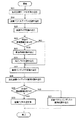
図10は、本発明の一実施形態に係る、法線ベクトルを含んだ三角形メッシュデータの圧縮方法を説明するためのフロー図である。
まず、三角形メッシュの頂点位置における座標からなる頂点座標テーブルを図4(頂点座標テーブル10)の形式に保存する(ステップS1)。次いで、三角形メッシュの頂点位置における法線ベクトルからなる法線ベクトルテーブルを図5(法線ベクトルテーブル20)の形式に保存する(ステップS2)。次いで、三角形メッシュ上の領域ごとの曲面タイプ(曲面タイプ=平面,球面,円柱面,円錐面,その他曲面のいずれか)を、図6の曲面タイプ0から曲面タイプna−1(曲面タイプフラグ配列32)の形式に保存する(ステップS3)。
【0043】
次いで、所定の曲面タイプ(平面,球面,円柱面,円錐面のいずれか)を持つかを判定し(ステップS4)、所定の曲面タイプを持つ領域に対し、すなわち領域が所定の曲面情報を持つ場合、それらの領域ごとに曲面情報を図7の形式で平面配列35,球面配列36,円柱面配列37,円錐面配列38のいずれかに保存し(ステップS5)、さらにそれらの領域ごとに曲面に対する三角形メッシュの向きフラグを図6の曲面の向き(曲面の向きフラグ配列33)の形式で保存する(ステップS6)。一方、領域が所定の曲面情報を持たない場合(曲面タイプ=その他曲面)、それらの領域ごとに三角形の法線ベクトルインデックス配列を図9(法線ベクトルインデックス配列50)の形式で保存する(ステップS7)。
【0044】
次いで、三角形メッシュの全ての領域に対し、領域ごとに、三角形を構成する頂点座標インデックス配列を図8(VIT40)の形式で保存する(ステップS8)。次いで、それらの領域ごとに三角形を構成する頂点座標インデックス配列の最終インデックスを図6におけるVITインデックス(VITインデックス配列34)の形式で保存する(ステップS9)。
以上により、法線ベクトルを含んだ三角形メッシュを圧縮することができる。
【0045】
図11は、本発明の一実施形態に係る、曲面情報に対する三角形メッシュの向きの判定方法を説明するためのフロー図である。
図10のステップS6において曲面の向きを判定する必要があるが、そのためには、まず、曲面上の点[p]における法線ベクトル[n([p])]を計算する(ステップS11)。ここでの計算方法は、曲面のタイプごとに異なり、次の計算式に基づいて計算する。
【0046】
【式2】
ここで、×はベクトルの外積ベクトル計算を表している。ここで求まるベクトルは正規化されていないので、最後にベクトルの正規化計算を行う(下式参照)。
【0048】
【式3】
次いで、三角形メッシュの一頂点について、その曲面上における法線ベクトルと三角形メッシュ上における法線ベクトルの内積を計算する(ステップS12)。次いで、この内積の結果により曲面情報に対する三角形メッシュの向きを判定する(ステップS13)。内積結果が正以上ならば同じ向きで、そうでなければ反対の向きと判定する。
以上により、曲面情報に対する三角形メッシュの向きの判定することができる。
【0050】
図12は、本発明の一実施形態に係る、法線ベクトルを含んだ三角形メッシュデータの伸長方法を説明するためのフロー図である。
まず、図4の形式の頂点座標テーブル10を読み込む(ステップS21)。次いで、図5の形式の法線ベクトルテーブル20を読み込む(ステップS22)。次いで、図6における曲面タイプフラグ配列32から三角形メッシュ上の領域ごとの曲面タイプを読み込む(ステップS23)。
【0051】
次いで、所定の曲面タイプ(平面,球面,円柱面,円錐面のいずれか)を持つかを判定し(ステップS24)、所定の曲面タイプを持つ領域に対し、すなわち領域が所定の曲面情報を持つ場合、図7の各形式でそれらの領域ごとに三角形メッシュ上の曲面情報を読み込み(ステップS25)、図6の向きフラグ配列33の形式でそれらの領域ごとに曲面情報に対する三角形メッシュの向きフラグを読み込む(ステップS26)。一方、領域が所定の曲面情報を持たない場合には、ステップS25,S26の処理は実行しない。
【0052】
次いで、図6におけるVITインデックス配列34から、三角形を構成する頂点座標インデックス配列の最終インデックスを領域ごとに読み込み(ステップS27)、図8の形式のVIT40において、それらの領域ごとに分けて、三角形を構成する頂点座標インデックス配列を読み込む(ステップS28)。
【0053】
次いで、所定の曲面タイプ(平面,球面,円柱面,円錐面のいずれか)を持つかを判定し(ステップS29)、或いはステップS24での判定結果に基づいて、領域が所定の曲面情報を持つ場合には、曲面情報,向きフラグ,頂点座標インデックス,頂点座標配列から法線ベクトルを計算する(ステップS30)。一方、領域が所定の曲面情報を持たない場合、三角形の頂点ごとの法線ベクトルインデックス配列を読み込む(ステップS31)。
以上により、法線ベクトルを含んだ三角形メッシュを伸長することができる。
【0054】
図13は、本発明の一実施形態に係る、法線ベクトルの計算方法を説明するためのフロー図である。
図12のステップS30において法線ベクトルを計算する必要があるが、そのためには、まず、VIT40の頂点座標インデックスを用いて頂点座標テーブル10から頂点座標を取得する(ステップS41)。次いで、その頂点座標を曲面上の点として、曲面上の点における法線ベクトルを計算する(ステップS42)。ここでの計算は、図11のステップS11と同じ方法で行う。曲面情報に対する三角形メッシュの向きフラグが違う向きを示しているならば、その法線ベクトルの逆方向の法線ベクトルに修正する(ステップS43)。
以上により、法線ベクトルが計算できる。
【0055】
本発明は、上述した法線ベクトル付三角形メッシュデータの圧縮及び/又は伸長方法や、法線ベクトルの計算方法、三角形メッシュの向きの判定方法を、コンピュータに実行させるためのプログラムとしての形態も、そのプログラム又はプログラム及びデータを記憶した記録媒体としての形態も採り得る。記録媒体としては、具体的には、CD−ROM,光磁気ディスク,DVD−ROM,FD,フラッシュメモリ,メモリスティック及びその他各種ROMやRAM等が想定でき、これら記録媒体にプログラム又はプログラム及びデータを記録し流通させることにより、法線ベクトル付三角形メッシュの圧縮及び/又は伸長の機能の実現を容易にする。そしてコンピュータ等の情報処理装置に記録媒体を装着してそのプログラムを読み出すか、若しくは情報処理装置が備えている記録媒体に当プログラムを記憶させておき、必要に応じて読み出すことにより、本発明に関わる機能を実行することができる。
【0056】
図14は、法線ベクトルを含んだ三角形メッシュデータを圧縮し伸長する1つ以上のコンピュータシステムの構成例を示す図である。
図14で例示する、情報処理装置としての各コンピュータシステムは、プロセスを実行するCPU72等の中央処理装置と、RAM71,データ記憶装置(データ保存装置)75等のメモリと、そのメモリに格納された(存在する)アプリケーションプログラム61及び圧縮データ構造とを備える。さらに、各コンピュータシステムは、I/Oインタフェース73を介して各種端末機器(キーボード,マウス,ディスプレイ等)74により入出力され、プリンタ76へも出力可能な構成になっている。
【0057】
アプリケーションプログラム61としては、本発明に係る圧縮プログラム62及び/又は伸長プログラム63を備え、それらがマイクロ命令コード67に基づくオペレーティングシステム(OS)66上で、コンパイラ64及びオプティマイザ65により実行可能となっている。
【0058】
図15は、図14に示した2つ以上のコンピュータシステムが通信リンクで接続された圧縮伸長システムの構成例を示す図である。
図15で例示する圧縮伸長システムは、本発明に係る圧縮のアルゴリズム82を備えた図14のごときコンピュータ81と、本発明に係る伸長のアルゴリズム85を備えた図14のごときコンピュータ84とが、通信リンクにより接続されている。ここでの通信リンクとしては、例えばインターネット,イントラネット,広域ネットワーク,ローカルエリアネットワーク,無線周波数リンク,赤外線リンク,シリアル通信リンクのいずれかを含めばよい。圧縮アルゴリズム82により圧縮された法線ベクトル付三角形メッシュデータ(圧縮モデル83)が、通信リンクを介してコンピュータ81で送信され、コンピュータ84で受信され、伸長アルゴリズム85により伸長されて表示等が可能となる。
【0059】
【発明の効果】
本発明によれば、非対称な位相の三角形メッシュのデータを圧縮・伸長した際の法線ベクトルの誤差を小さくすることができる。本発明によれば、さらに非一様な密度の三角形メッシュのデータを圧縮・伸長した際にも、法線ベクトルの誤差を小さくすることができる。本発明を3次元CADシステムなどに実現することによって、コンパクトな3次元データを実現することができる。
【図面の簡単な説明】
【図1】 解析的曲面の例を示す図である。
【図2】 Bezier曲面の一例を示す図である。
【図3】 本発明の一実施形態に係る、n次元空間の三角形メッシュのデータ構造を説明するための図である。
【図4】 図3の三角形メッシュのデータ構造における頂点座標テーブルのデータ構造を説明するための図である。
【図5】 図3の三角形メッシュのデータ構造における法線ベクトルテーブルのデータ構造を説明するための図である。
【図6】 図3の三角形メッシュのデータ構造における曲面情報テーブルのデータ構造を説明するための図である。
【図7】 図6の曲面情報テーブルのデータ構造における、平面配列,球面配列,円柱面配列,円錐面配列の各データ構造を説明するための図である。
【図8】 図3の三角形メッシュのデータ構造における頂点座標インデックステーブルのデータ構造を説明するための図である。
【図9】 図3の三角形メッシュのデータ構造における法線ベクトルインデックステーブルのデータ構造を説明するための図である。
【図10】 本発明の一実施形態に係る、法線ベクトルを含んだ三角形メッシュデータの圧縮方法を説明するためのフロー図である。
【図11】 本発明の一実施形態に係る、曲面情報に対する三角形メッシュの向きの判定方法を説明するためのフロー図である。
【図12】 本発明の一実施形態に係る、法線ベクトルを含んだ三角形メッシュデータの伸長方法を説明するためのフロー図である。
【図13】 本発明の一実施形態に係る、法線ベクトルの計算方法を説明するためのフロー図である。
【図14】 法線ベクトルを含んだ三角形メッシュデータを圧縮し伸長する1つ以上のコンピュータシステムの構成例を示す図である。
【図15】 図14に示した2つ以上のコンピュータシステムが通信リンクで接続された圧縮伸長システムの構成例を示す図である。
【図16】 三角形メッシュの例を示す図である。
【図17】 三角形メッシュの位相の違いを説明するための図である。
【図18】 三角形メッシュの密度の違いを説明するための図である。
【符号の説明】
1…三角形メッシュのデータ構造、10…頂点座標テーブル、11…頂点座標の数、120,121,12n-1…頂点座標の各成分、20…法線ベクトルテーブル、21…法線ベクトルの数、220,221,22m-1…法線ベクトルの各成分、30…曲面情報テーブル、31…三角形メッシュの領域数、32…曲面タイプフラグ配列、33…向きフラグ配列、34…VITのインデックス配列、35…平面配列、36…球面配列、37…円柱面配列、38…円錐面配列、40…頂点座標インデックステーブル、41…頂点座標インデックス数、420,421,42nv−1…頂点座標インデックス、50…法線ベクトルインデックステーブル、51…法線ベクトルインデックスの数、520,521,52nn−1…法線ベクトルインデックス、61…アプリケーションプログラム、62…圧縮プログラム、63…伸長プログラム、64…コンパイラ、65…オプティマイザ、66…オペレーティングシステム、67…マイクロ命令コード、71…RAM、72…CPU、73…I/Oインタフェース、74…端末機器、75…データ記憶装置、76…プリンタ、81,84…コンピュータ、82…圧縮のアルゴリズム、83…圧縮モデル。[0001]
BACKGROUND OF THE INVENTION
The present inventionthreeCompression method of square mesh data andBipLograMuMore specifically, it can be used for a three-dimensional shape model generation device, a three-dimensional shape model display device, and the like.threeCompression method of square mesh data andBipLograToRelated. Examples of the application field of the present invention include a shape measuring device and a virtual reality device.
[0002]
[Prior art]
The free-form surface is widely used in CAD as a means for expressing a three-dimensional shape model. In order to display a three-dimensional shape model, it is necessary to convert the free-form surface into data in a triangular mesh format. Since this conversion work takes time, it is widely performed to store data converted into a triangular mesh in advance together with free-form surface data. In addition, viewers dedicated to 3D shape models that cannot be deformed for the purpose of arranging catalogs and parts are becoming popular. For this reason, there are many studies on techniques for compressing the data size when a free-form surface is converted into a triangular mesh. References for this technology include, for example, “Taubin G and Rossignac J: Geometry compression through topological surgery, ACM Transactions on Graphics, Vol. 17, No. 2, 1998”.
[0003]
On the other hand, when rendering and displaying a triangular mesh generated by these methods, normal vector data for each vertex of each triangle constituting the mesh is required. This is because a rendering display algorithm such as von shading enables a realistic glossy texture expression by using a normal vector.
[0004]
The von shading is a technique for performing shading by obtaining a normal vector of a point inside a triangle from the normal vector of the vertex of the triangular mesh by interpolating the normal vector of the point inside the triangle. Shading is a method for calculating the brightness (color) of an object surface from the direction and intensity of light, the nature of reflection on the object surface, the direction of line of sight, and the like.
[0005]
FIG. 16 is a diagram showing an example of a triangular mesh, FIG. 16A is an example of the original cylindrical surface shape, FIG. 16B is an example of approximation by the triangular mesh, and FIG. 16C is another triangular mesh. FIG. 4 is a diagram showing examples of non-uniform triangular meshes. 17A and 17B are diagrams for explaining the phase difference of a triangular mesh. FIG. 17A shows an example in which the phase is asymmetric with respect to the central vertex, and FIG. 17B shows an example in which the phase is symmetrical with respect to the central vertex. FIG. 18A and 18B are diagrams for explaining the difference in density of triangular meshes. FIG. 18A is a non-uniform cross section (FIG. 16C), and FIG. 18B is uniform (16). It is a figure which shows the example of the cross section of (B).
[0006]
In general, in the case of a triangular mesh generated from a free-form surface, the normal vector can be estimated by calculating the average of the vectors of the triangles adjacent to the vertex, so the data size can be reduced by omitting the saving of the normal vector. Is possible.
[0007]
However, an error may occur due to the arrangement of triangles at the vertices for which a normal vector is to be obtained. First, considering the cylindrical triangular mesh (FIG. 16B) shown in FIG. 16A, in the case of an asymmetric triangle arrangement as shown in FIG. Many tilt to the lower left.
[0008]
On the other hand, in the case of the symmetrical triangle arrangement as shown in FIG. 17B, the above-mentioned problem does not occur, but in the case of a non-uniform triangle mesh as shown in FIG. As shown in (2), the problem of the deviation of the normal vector occurs regardless of whether the triangular arrangement is symmetrical or not.
[0009]
[Problems to be solved by the invention]
The present invention has been made in view of the above-described circumstances, and asymmetric phase triangular mesh data.Or non-uniform density triangle mesh dataEven when stretched, a large error occurs in the normal vectorNeverTriangular mesh data compression method andBipLograTheIts purpose is to provide.
[0010]
[Means for Solving the Problems]
The invention of claim 1In the triangular mesh data compression method for compressing triangular mesh data corresponding to curved surface data, the control device stores a vertex coordinate table including coordinate information at the vertex positions of the triangular mesh in a storage device; and the control A device storing a normal vector table comprising information on normal vectors at vertex positions of the triangular mesh in the storage device; and the control device is configured as a curved surface type for each region on the triangular mesh. , A spherical surface, a cylindrical surface, a conical surface, or any other type are stored in the storage device, and the control device is a surface, spherical surface, cylindrical surface, or conical surface type. For an area showing a certain curved surface, obtain a direction flag indicating the direction of the triangular mesh with respect to the curved surface, and Storing in a storage device; and storing the normal vector index array for each vertex of a triangle in the storage device for an area where the curved surface type indicates a curved surface other than the predetermined curved surface; The control device stores a vertex coordinate index array that constitutes a triangle divided into regions on the triangle mesh in the storage device, and the control device stores the final vertex coordinate index array for each region. Storing an index in the storage device, and the orientation flag calculates a normal vector at a point on the curved surface, and calculates an inner product of the calculated normal vector and the normal vector on the triangular mesh. , By determining the direction of the triangular mesh with respect to the curved surface information according to the result of the inner productIt is characterized by that.
[0011]
The invention of claim 2A program for causing a computer to execute the triangle mesh data compression method according to claim 1.It is.
[0027]
DETAILED DESCRIPTION OF THE INVENTION
The configuration and operation of the present invention will be described based on the following assumptions (a), (b), (c), and (d).
(A) The free curved surface handled in the present invention includes a parametric curved surface and an analytical curved surface.
(B) The analytical curved surface treated as a predetermined curved surface in the present invention includes a plane, a spherical surface, a cylindrical surface, and a conical surface, which are defined as follows. That is, the plane is the origin coordinate [opl] And normal vector [npl], The spherical surface is center coordinates [csp] And radius value rspThen, the cylindrical surface has a center coordinate [ccy], Axis vector [acy], Radius value rcyAnd the conical surface is the vertex coordinate [qco], Axis vector [aco], Radius value r at the point advanced by 1 in the axial directioncoDefined in However, in the present specification, the vector display of an arbitrary A is also expressed as [A]. FIG. 1 shows an example of an analytical curved surface. 1A is an example of a plane, FIG. 1B is a spherical surface, FIG. 1C is a cylindrical surface, and FIG. 1D is a conical surface.
[0028]
(C) The points on the parametric curved surface handled in the present invention are represented by parameters u and v as follows.
[S (u, v)] (0 ≦ u, v ≦ 1)
[0029]
A Bezier curved surface, which is a typical parametric curved surface, will be introduced. An n × m-order Bezier curved surface [S (u, v)] has (n + 1) × (m + 1) control points [PijThe point on the curved surface is expressed by the following equation. Bi n(U), Bj m(V) is a function called Bernstein basis function.
[0030]
[Formula 1]
FIG. 2 shows a bicubic Bezier curved surface as an example of a Bezier curved surface. The bicubic Bezier curved surface has 16 control points [Pij] (I = 0, 1, 2, 3; j = 0, 1, 2, 3).
[0032]
(D) Triangular mesh expression formats handled in the present invention include a triangular index set format, a triangular index strip format, and a triangular index fan format. Corresponding to the primitives of GL_TRIANGLES, GL_TRIANGLE_STRIP, and GL_TRIANGLE_FAN on page 19. These indexed formats are formats in which a coordinate table is separately held in an array format, and coordinates are expressed by specifying an array index.
[0033]
FIG. 3 is a diagram for explaining a data structure of a triangular mesh in an n-dimensional space according to an embodiment of the present invention.
The
[0034]
FIG. 4 is a diagram for explaining the data structure of the vertex coordinate table in the data structure of the triangular mesh of FIG.
The vertex coordinate table 10 illustrated in FIG. 4 includes a vertex coordinate number (= n) 11 and x, y, and
[0035]
FIG. 5 is a diagram for explaining the data structure of the normal vector table in the data structure of the triangular mesh of FIG.
The normal vector table 20 illustrated in FIG. 5 includes the number of normal vectors (= m) 21 and x, y, and
[0036]
FIG. 6 is a diagram for explaining the data structure of the curved surface information table in the data structure of the triangular mesh in FIG.
The curved surface information table 30 illustrated in FIG. 6 includes the number of triangular mesh regions (= na) 31 and curved surface type 0 to curved surface type naCurved surface
[0037]
Curved surface type flag array 32 (number of elements = na) Is an array of flags indicating the surface type for each triangular mesh region. The curved surface type is one of five integer values representing a flat surface, a spherical surface, a cylindrical surface, a conical surface, and other curved surfaces. Direction flag array 33 (number of elements = nsf) Is an array of flags indicating the direction of the triangular mesh with respect to the curved surface information for each region for a region whose curved surface type is other than a curved surface (that is, any one of a plane, a spherical surface, a cylindrical surface, and a conical surface). The direction flag of the triangular mesh with respect to the curved surface (curved surface information) is an integer representing a logical value indicating whether or not the mesh direction and the curved surface direction match. VIT index array 34 (number of elements = na) Is an array storing the indices of the vertex coordinate index array for each region. Also, the number of elements of the planar array is npl, The number of elements of the spherical array is nsp, The number of elements of the cylindrical arraycy, The number of elements in the conical array is ncoIt is said. Nsf= Npl+ Nsp+ Ncy+ NcoIt becomes.
[0038]
FIG. 7 is a diagram for explaining each data structure of a plane array, a spherical array, a cylindrical surface array, and a conical surface array in the data structure of the curved surface information table of FIG.
A
[0039]
FIG. 8 is a diagram for explaining the data structure of the vertex coordinate index table in the data structure of the triangular mesh of FIG.
In the vertex coordinate index table (VIT) 40, the number of vertex coordinate indexes 41 (= nv) And vertex coordinate index 0 to vertex coordinate index nvVertex coordinate
[0040]
FIG. 9 is a diagram for explaining the data structure of the normal vector index table in the data structure of the triangular mesh of FIG.
The normal vector index table 50 includes 51 normal vector index numbers (= nn) And normal vector index 0 to normal vector index nn
[0041]
By using the data structure of the triangular mesh described above, it is possible to compress and decompress triangular mesh data including normal vectors. With reference to FIGS. 3 to 9 again, a method for compressing and decompressing triangular mesh data will be described below.
[0042]
FIG. 10 is a flowchart for explaining a method of compressing triangular mesh data including normal vectors according to an embodiment of the present invention.
First, a vertex coordinate table including coordinates at the vertex positions of the triangular mesh is stored in the format of FIG. 4 (vertex coordinate table 10) (step S1). Next, a normal vector table composed of normal vectors at the vertex positions of the triangular mesh is stored in the format of FIG. 5 (normal vector table 20) (step S2). Next, the surface type (surface type = plane, spherical surface, cylindrical surface, conical surface, or other curved surface) for each region on the triangular mesh is changed from surface type 0 to surface type n in FIG.a-1 (curved surface type flag array 32) is saved (step S3).
[0043]
Next, it is determined whether or not it has a predetermined curved surface type (plane, spherical surface, cylindrical surface, or conical surface) (step S4), and the region has predetermined curved surface information with respect to the region having the predetermined curved surface type. In this case, the curved surface information is stored in one of the
[0044]
Next, for every region of the triangular mesh, the vertex coordinate index array constituting the triangle is stored in the format of FIG. 8 (VIT40) for each region (step S8). Next, the final index of the vertex coordinate index array constituting the triangle for each area is stored in the format of the VIT index (VIT index array 34) in FIG. 6 (step S9).
As described above, the triangular mesh including the normal vector can be compressed.
[0045]
FIG. 11 is a flowchart for explaining a method for determining the orientation of a triangular mesh with respect to curved surface information according to an embodiment of the present invention.
In step S6 in FIG. 10, it is necessary to determine the direction of the curved surface. To do so, first, a normal vector [n ([p])] at a point [p] on the curved surface is calculated (step S11). The calculation method here is different for each type of curved surface, and is calculated based on the following calculation formula.
[0046]
[Formula 2]
Here, x represents vector cross product vector calculation. Since the vector obtained here is not normalized, vector normalization calculation is finally performed (see the following formula).
[0048]
[Formula 3]
Next, for one vertex of the triangular mesh, the inner product of the normal vector on the curved surface and the normal vector on the triangular mesh is calculated (step S12). Next, the orientation of the triangular mesh with respect to the curved surface information is determined based on the result of the inner product (step S13). If the inner product result is greater than or equal to the positive value, the direction is the same. Otherwise, the opposite direction is determined.
As described above, the direction of the triangular mesh with respect to the curved surface information can be determined.
[0050]
FIG. 12 is a flowchart for explaining a method of decompressing triangular mesh data including a normal vector according to an embodiment of the present invention.
First, the vertex coordinate table 10 in the format of FIG. 4 is read (step S21). Next, the normal vector table 20 in the format of FIG. 5 is read (step S22). Next, the surface type for each region on the triangular mesh is read from the surface
[0051]
Next, it is determined whether or not it has a predetermined curved surface type (plane, spherical surface, cylindrical surface, or conical surface) (step S24), and the region has a predetermined curved surface information with respect to the region having the predetermined curved surface type. In this case, the curved surface information on the triangular mesh is read for each area in each format of FIG. 7 (step S25), and the orientation flag of the triangular mesh for the curved surface information is read for each area in the format of the
[0052]
Next, the final index of the vertex coordinate index array constituting the triangle is read for each region from the
[0053]
Next, it is determined whether it has a predetermined curved surface type (plane, spherical surface, cylindrical surface, or conical surface) (step S29), or the region has predetermined curved surface information based on the determination result in step S24. In this case, a normal vector is calculated from the curved surface information, the orientation flag, the vertex coordinate index, and the vertex coordinate array (step S30). On the other hand, if the region does not have the predetermined curved surface information, the normal vector index array for each vertex of the triangle is read (step S31).
As described above, the triangular mesh including the normal vector can be expanded.
[0054]
FIG. 13 is a flowchart for explaining a normal vector calculation method according to an embodiment of the present invention.
In step S30 of FIG. 12, it is necessary to calculate the normal vector. For this purpose, first, vertex coordinates are acquired from the vertex coordinate table 10 using the vertex coordinate index of the VIT 40 (step S41). Next, using the vertex coordinates as points on the curved surface, a normal vector at the point on the curved surface is calculated (step S42). The calculation here is performed by the same method as step S11 in FIG. If the direction flag of the triangular mesh with respect to the curved surface information indicates a different direction, it is corrected to a normal vector in the reverse direction of the normal vector (step S43).
Thus, the normal vector can be calculated.
[0055]
The present invention also includes a form as a program for causing a computer to execute the above-described method for compressing and / or decompressing triangular mesh data with a normal vector, a method for calculating a normal vector, and a method for determining the direction of a triangular mesh. The form as a recording medium which memorize | stored the program or a program, and data can also be taken. Specifically, a CD-ROM, magneto-optical disk, DVD-ROM, FD, flash memory, memory stick, and various other ROMs and RAMs can be assumed as the recording medium. By recording and distributing, it becomes easy to realize the function of compression and / or expansion of the triangle mesh with normal vector. Then, the recording medium is loaded into an information processing apparatus such as a computer and the program is read out, or the program is stored in a recording medium provided in the information processing apparatus and read out as necessary. Can perform related functions.
[0056]
FIG. 14 is a diagram illustrating a configuration example of one or more computer systems that compress and decompress triangular mesh data including normal vectors.
Each computer system as an information processing apparatus illustrated in FIG. 14 is stored in a central processing unit such as a
[0057]
The
[0058]
FIG. 15 is a diagram illustrating a configuration example of a compression / decompression system in which two or more computer systems illustrated in FIG. 14 are connected via a communication link.
In the compression / decompression system illustrated in FIG. 15, the
[0059]
【The invention's effect】
According to the present invention, it is possible to reduce an error of a normal vector when compressing and expanding data of a triangular mesh having an asymmetric phase. According to the present invention, the error of the normal vector can be reduced even when the data of the triangular mesh having a non-uniform density is compressed and expanded. By realizing the present invention in a three-dimensional CAD system or the like, compact three-dimensional data can be realized.
[Brief description of the drawings]
FIG. 1 is a diagram showing an example of an analytical curved surface.
FIG. 2 is a diagram illustrating an example of a Bezier curved surface.
FIG. 3 is a diagram for explaining a data structure of a triangular mesh in an n-dimensional space according to an embodiment of the present invention.
4 is a diagram for explaining a data structure of a vertex coordinate table in the data structure of a triangular mesh in FIG. 3; FIG.
5 is a diagram for explaining a data structure of a normal vector table in the data structure of the triangular mesh in FIG. 3; FIG.
6 is a diagram for explaining a data structure of a curved surface information table in the data structure of a triangular mesh in FIG. 3; FIG.
7 is a diagram for explaining each data structure of a planar array, a spherical array, a cylindrical surface array, and a conical surface array in the data structure of the curved surface information table of FIG. 6;
8 is a diagram for explaining a data structure of a vertex coordinate index table in the data structure of the triangular mesh in FIG. 3; FIG.
9 is a diagram for explaining a data structure of a normal vector index table in the data structure of the triangular mesh in FIG. 3; FIG.
FIG. 10 is a flowchart for explaining a method of compressing triangular mesh data including a normal vector according to an embodiment of the present invention.
FIG. 11 is a flowchart for explaining a method of determining the orientation of a triangular mesh with respect to curved surface information according to an embodiment of the present invention.
FIG. 12 is a flowchart for explaining a method of decompressing triangular mesh data including a normal vector according to an embodiment of the present invention.
FIG. 13 is a flowchart for explaining a normal vector calculation method according to an embodiment of the present invention;
FIG. 14 is a diagram illustrating a configuration example of one or more computer systems that compress and decompress triangular mesh data including normal vectors.
15 is a diagram showing a configuration example of a compression / decompression system in which two or more computer systems shown in FIG. 14 are connected by a communication link.
FIG. 16 is a diagram illustrating an example of a triangular mesh.
FIG. 17 is a diagram for explaining a phase difference of a triangular mesh.
FIG. 18 is a diagram for explaining a difference in density of a triangular mesh.
[Explanation of symbols]
DESCRIPTION OF
Claims (2)
制御装置が、前記三角形メッシュの頂点位置における座標の情報からなる頂点座標テーブルを、記憶装置に保存するステップと、
前記制御装置が、前記三角形メッシュの頂点位置における法線ベクトルの情報からなる法線ベクトルテーブルを、前記記憶装置に保存するステップと、
前記制御装置が、前記三角形メッシュ上の領域ごとに、曲面タイプとして平面,球面,円柱面,円錐面,その他のいずれかのタイプを、前記記憶装置に保存するステップと、
前記制御装置が、前記曲面タイプが平面,球面,円柱面,円錐面のいずれかのタイプである所定曲面を示す領域に対し、曲面に対する三角形メッシュの向きを表す向きフラグを求めて、前記記憶装置に保存するステップと、
前記制御装置が、前記曲面タイプが前記所定曲面以外の曲面を示す領域に対し、三角形の頂点ごとの法線ベクトルインデックス配列を、前記記憶装置に保存するステップと、
前記制御装置が、前記三角形メッシュ上の領域ごとに分けて三角形を構成する頂点座標インデックス配列を、前記記憶装置に保存するステップと、
前記制御装置が、前記領域ごとに前記頂点座標インデックス配列の最終インデックスを、前記記憶装置に保存するステップとを含み、
前記向きフラグは、曲面上の点における法線ベクトルを計算し、該計算した法線ベクトルと三角形メッシュ上における法線ベクトルの内積を計算し、該内積の結果により曲面情報に対する三角形メッシュの向きを判定することにより、求めることを特徴とする三角形メッシュデータ圧縮方法。 In a triangular mesh data compression method for compressing triangular mesh data corresponding to curved surface data,
A control device storing a vertex coordinate table comprising information of coordinates at the vertex positions of the triangular mesh in a storage device;
The control device storing a normal vector table consisting of information on normal vectors at the vertex positions of the triangular mesh in the storage device;
The controller stores, for each region on the triangular mesh, a plane type, a spherical surface, a cylindrical surface, a conical surface, or any other type as a curved surface type in the storage device;
The control device obtains an orientation flag indicating the orientation of a triangular mesh with respect to a curved surface for an area indicating a predetermined curved surface whose curved surface type is any one of a plane, a spherical surface, a cylindrical surface, and a conical surface, and the storage device The steps to save in
The control device stores, in the storage device, a normal vector index array for each vertex of a triangle for an area where the curved surface type indicates a curved surface other than the predetermined curved surface;
Storing the vertex coordinate index array constituting the triangle divided into regions on the triangular mesh in the storage device, the control device;
Storing the final index of the vertex coordinate index array for each region in the storage device;
The orientation flag, the normal vector calculated at a point on the curved surface, to calculate the inner product of the normal vector at the calculated normal vectors and triangles on the mesh, the orientation of the triangular mesh for curved information as a result of the inner product by determining, triangle mesh data compression how to and finding.
Priority Applications (1)
| Application Number | Priority Date | Filing Date | Title |
|---|---|---|---|
| JP2002213608A JP4017467B2 (en) | 2002-07-23 | 2002-07-23 | Triangular mesh data compression method and program |
Applications Claiming Priority (1)
| Application Number | Priority Date | Filing Date | Title |
|---|---|---|---|
| JP2002213608A JP4017467B2 (en) | 2002-07-23 | 2002-07-23 | Triangular mesh data compression method and program |
Publications (2)
| Publication Number | Publication Date |
|---|---|
| JP2004054736A JP2004054736A (en) | 2004-02-19 |
| JP4017467B2 true JP4017467B2 (en) | 2007-12-05 |
Family
ID=31936163
Family Applications (1)
| Application Number | Title | Priority Date | Filing Date |
|---|---|---|---|
| JP2002213608A Expired - Fee Related JP4017467B2 (en) | 2002-07-23 | 2002-07-23 | Triangular mesh data compression method and program |
Country Status (1)
| Country | Link |
|---|---|
| JP (1) | JP4017467B2 (en) |
Families Citing this family (5)
| Publication number | Priority date | Publication date | Assignee | Title |
|---|---|---|---|---|
| JP2015184061A (en) * | 2014-03-20 | 2015-10-22 | 株式会社東芝 | Extracting device, method, and program |
| CN109308734B (en) * | 2017-07-27 | 2023-01-06 | 腾讯科技(深圳)有限公司 | 3D character generation method and device, equipment and storage medium thereof |
| CN110310358B (en) * | 2018-03-21 | 2023-10-03 | 杭州逍度网络科技有限公司 | Method for realizing pixel-by-pixel illumination operation |
| CN113674296A (en) * | 2021-09-03 | 2021-11-19 | 广东三维家信息科技有限公司 | Region cutting method and device, electronic equipment and storage medium |
| CN115661285B (en) * | 2022-10-27 | 2023-09-22 | 东莘电磁科技(成都)有限公司 | Regular curved surface-borne antenna time-harmonic near-field induction characteristic image generation method |
-
2002
- 2002-07-23 JP JP2002213608A patent/JP4017467B2/en not_active Expired - Fee Related
Also Published As
| Publication number | Publication date |
|---|---|
| JP2004054736A (en) | 2004-02-19 |
Similar Documents
| Publication | Publication Date | Title |
|---|---|---|
| US6522326B1 (en) | Decompression of quantized compressed three-dimensional graphics data | |
| JP2001052194A (en) | Reconfiguration for curved surface | |
| US7545375B2 (en) | View-dependent displacement mapping | |
| EP1705589B1 (en) | Method for approximating and displaying three-dimensional cad data, and system for executing that method | |
| JPWO2006062199A1 (en) | Three-dimensional image data compression apparatus, method, program, and recording medium | |
| WO2008013605A1 (en) | Real-time gpu rendering of piecewise algebraic surfaces | |
| EP3563353A1 (en) | Systems and methods for lightweight precise 3d visual format | |
| JP2011070326A (en) | Image processing apparatus, and image processing method | |
| CN113724401A (en) | Three-dimensional model cutting method and device, computer equipment and storage medium | |
| US7342580B1 (en) | Surface compression based on reference geometry in animation models | |
| CN109697748B (en) | Model compression processing method, model mapping processing method, model compression processing device, and storage medium | |
| JP4017467B2 (en) | Triangular mesh data compression method and program | |
| JPH1196345A (en) | Method for compressing and inversely compressing graphics image | |
| US20210312590A1 (en) | Graphics processing using matrices of transformations | |
| CN115713585B (en) | Texture image reconstruction method, apparatus, computer device and storage medium | |
| US6246805B1 (en) | Efficient beveling of extruded regions in video processing | |
| JP2837584B2 (en) | How to create terrain data | |
| JPH11316854A (en) | Method and system for data organization for three-dimensional graphics pipeline | |
| US7015917B2 (en) | Curved surface subdivision apparatus | |
| JP2010128618A (en) | Image processing apparatus, and image processing method | |
| JP2004102834A (en) | Structure of triangular mesh data, method of compressing and expanding triangular mesh data, program, recording medium, and system | |
| JP2012230663A (en) | Image processor and image processing method | |
| JP2655056B2 (en) | Texture data generator | |
| JP3104643B2 (en) | Image processing apparatus and image processing method | |
| JP2891862B2 (en) | Image compression apparatus and image compression method |
Legal Events
| Date | Code | Title | Description |
|---|---|---|---|
| A621 | Written request for application examination |
Free format text: JAPANESE INTERMEDIATE CODE: A621 Effective date: 20050203 |
|
| A131 | Notification of reasons for refusal |
Free format text: JAPANESE INTERMEDIATE CODE: A131 Effective date: 20070626 |
|
| A521 | Written amendment |
Free format text: JAPANESE INTERMEDIATE CODE: A523 Effective date: 20070822 |
|
| TRDD | Decision of grant or rejection written | ||
| A01 | Written decision to grant a patent or to grant a registration (utility model) |
Free format text: JAPANESE INTERMEDIATE CODE: A01 Effective date: 20070918 |
|
| A61 | First payment of annual fees (during grant procedure) |
Free format text: JAPANESE INTERMEDIATE CODE: A61 Effective date: 20070918 |
|
| R150 | Certificate of patent or registration of utility model |
Free format text: JAPANESE INTERMEDIATE CODE: R150 |
|
| FPAY | Renewal fee payment (event date is renewal date of database) |
Free format text: PAYMENT UNTIL: 20100928 Year of fee payment: 3 |
|
| FPAY | Renewal fee payment (event date is renewal date of database) |
Free format text: PAYMENT UNTIL: 20110928 Year of fee payment: 4 |
|
| FPAY | Renewal fee payment (event date is renewal date of database) |
Free format text: PAYMENT UNTIL: 20120928 Year of fee payment: 5 |
|
| FPAY | Renewal fee payment (event date is renewal date of database) |
Free format text: PAYMENT UNTIL: 20130928 Year of fee payment: 6 |
|
| LAPS | Cancellation because of no payment of annual fees |