JP4014941B2 - Arrival direction estimation apparatus and arrival direction estimation method - Google Patents
Arrival direction estimation apparatus and arrival direction estimation method Download PDFInfo
- Publication number
- JP4014941B2 JP4014941B2 JP2002168150A JP2002168150A JP4014941B2 JP 4014941 B2 JP4014941 B2 JP 4014941B2 JP 2002168150 A JP2002168150 A JP 2002168150A JP 2002168150 A JP2002168150 A JP 2002168150A JP 4014941 B2 JP4014941 B2 JP 4014941B2
- Authority
- JP
- Japan
- Prior art keywords
- correction value
- arrival
- antenna
- arrival direction
- obstacle
- Prior art date
- Legal status (The legal status is an assumption and is not a legal conclusion. Google has not performed a legal analysis and makes no representation as to the accuracy of the status listed.)
- Expired - Fee Related
Links
Images


Description
【0001】
【発明の属する技術分野】
この発明は移動体通信用基地局、電波監視装置、レ−ダ装置などで用いられる到来波方向推定装置に関する。
【0002】
【従来の技術】
移動体通信用基地局、電波監視装置、レ−ダ装置においては、到来してくる電波の方向を精度良く推定する到来方向推定装置が望まれている。
【0003】
高精度に到来方向を推定する方法として、複数のアンテナ素子の受信信号を用いるMUSIC(Multiple Signal Classification)(R。 O。 Schmit、“Multple Emitter Location and Signal Parameter Estimation”、IEEE Trans。 Antennas and Propagation、 vol。AP−34、 no。3、 pp。 276−280、 March、 1986。)が存在する。
【0004】
このMUSICを用いた到来方向推定装置は、複数のアンテナ、複数のアンテナにそれぞれ接続された複数の受信器、複数の受信器に接続された到来方向推定手段とから構成される。到来方向推定手段は、すべてのアンテナからの受信信号と使用しているアンテナパタ−ン(振幅と位相)を用いて到来方向推定を行う。
【0005】
MUSICを用いて精度良く到来方向推定を行うためには、アンテナおよび受信器のキャリブレ−ションが重要である。キャリブレ−ションが不完全であると到来方向の推定誤差が大きくなり精度が大幅に劣化してしまう。
【0006】
アンテナおよび受信器のキャリブレ−ション方法は、特開2001−217760号公報の「アダプティブアンテナの校正方法」に示されている。アダプティブアンテナでは到来方向を推定し、その方向にビ−ムを向けたりする機能も有しているので、到来方向推定装置を含んでいるものである。
【0007】
このキャリブレ−ション方法は、既知の方向に送信装置を設置し、送信装置からの送信波を到来方向推定装置に設けられた複数のアンテナで受信する。この受信信号は到来方向推定装置に設けられたアナログ受信器及びA/D変換器を通過して、デジタル信号に変換される。到来方向推定装置からみた送信装置の方向と複数のアンテナの配置が既知であり、また、到来方向推定装置の複数のアナログ受信器の特性が同一であれば、デジタル信号の位相差は所定の値となり、また、振幅も所定の値となる。
【0008】
ところが、一般的にアンテナおよびアナログ受信器はばらつきを有しているために、振幅と位相は所定の値とならない。そこで、振幅と位相を所望の値とする為の校正値を計算する。これをデジタル受信信号へ乗算することで、キャリブレ−ションすることが可能となる。
【0009】
ところが、上述の方法は、設計段階では予期していない看板、柱などの電波の散乱、吸収をする障害物がアンテナ近傍に存在し、アンテナパタ−ンが角度によって異なる変化をした場合には、キャリブレ−ションすることが不可能となる。何故ならば、送信装置は特定の方向にしかないために、その方向のみの校正値しか求めることができない。特に、地震などの災害時に到来方向推定装置の近傍に障害物が存在してしまった場合には、大きな問題となる可能性がある。
【0010】
また、MUSICを用いて到来方向推定を行う場合には、アンテナの振幅と位相パタ−ンを用いて到来方向推定を行うので、アンテナパタ−ンのキャリブレ−ションができない場合には推定精度が劣化する大きな問題となる。
【0011】
このような場合の解決方法としては、全ての方向に送信装置を配置し、全ての方向の校正値を求めれば良い。ところが、全ての方向に送信装置を置くことはコスト的に大きな問題があり、現実的でない。
【0012】
他の方法として、看板、柱等の影響を数値シミュレ−ションなどで明確にする方法がある。ところがこの場合にも、到来方向推定装置を設置した後に、看板の形が変わったり、位置が変わったり、あるいは、電気的な媒質定数が変化する可能性がある。
また、障害物が複雑な形状となった場合には、数値シミュレ−ションを実行できない場合もある。
【0013】
以上説明したように、従来の到来方向推定装置におけるキャリブレ−ション方法は、アンテナパタ−ンそのものが、障害物の影響で変化してしまった場合には、適用することができない問題点があった。また、障害物の影響を数値シミュレ−ションで定量評価することも可能だが、簡易な構造の障害物であり、かつ、時間的に変化しない場合のみに適用できる方法であるために、適用できる場合が極めて限定されてしまう問題があった。
【0014】
【発明が解決しようとする課題】
以上説明したように、従来の到来方向推定装置におけるキャリブレ−ション方法では、角度特性のないキャリブレ−ションは可能であったが、角度特性を有するアンテナパタ−ンのキャリブレ−ションを行うことができない問題点があった。
【0015】
本発明は、このような従来の問題点に鑑みてなされたもので、アンテナパタ−ンのキャリブレ−ションを可能とし、高精度に到来方向の推定が可能な到来方向推定装置を提供することを目的とする。
【0016】
【課題を解決するための手段】
上記課題を解決するための本発明の到来方向推定装置及び到来方向推定方法は、
到来方向が既知の電波を受信し、これら受信信号を用いて前記既知の電波に対するアンテナ振幅パタ−ンの補正値とアンテナ位相パタ−ンの補正値をそれぞれ算出し、この算出した補正値をもとに前記補正値を算出した前記複数の既知の電波の2方向の角度差が、あらかじめ設定した値よりも小さい場合に2方向間の補間補正値を補間計算で算出し、これら補間補正値、前記算出した補正値及び前記受信信号用いて、電波の到来方向推定を行うことを特徴とするものである。
【0019】
【発明の実施の形態】
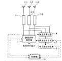
以下、本発明の第1の実施の形態について図面を参照しながら説明する。図1は本発明に係わる到来方向推定装置の構成図である。到来方向推定装置は、到来してくる電波を受信する複数のアンテナ素子(1−1〜1−3)と、アンテナ素子(1−1〜1−3)にそれぞれ接続する複数の受信器(2−1〜2−3)と、到来方向が既知の電波の受信信号を用いて、その方向の、アンテナ振幅パタ−ンの補正値とアンテナ位相パタ−ンの補正値を算出する補正値算出手段4と、補正値を保存する補正値保存器5と、補正値の算出されている2方向の角度差があらかじめ設定した値よりも小さい場合には、2方向間の補正値を補間計算で算出する補正値補間器6と受信器の受信信号と補正値保存器で保存されている補正値を用いて電波の到来方向推定を行う到来方向推定器3とから構成されている。また、これら到来方向推定器3、補正値算出手段4、補正値保存器5、補正値補間器6は制御部10からの制御信号により動作している。
【0020】
本実施の形態における到来方向推定装置は、到来方向推定装置の近傍に存在する設計段階では予想できない障害物の影響によるアンテナパタ−ンの変化量を補正することが可能であることを特徴とする。以下、本実施の形態の詳細について説明する。なお、ここでの説明は理解を容易にするためにアンテナ素子を3素子にしている。
アンテナ素子(1−1〜1−3)は到来してくる電波を受信できる様に設計されていれば、どのようなアンテナを用いても良い。ビ−ム幅の広いダイポ−ルアンテナでも良いし、ビ−ム幅の狭い八木・宇田アンテナでも良い。また、複数のアンテナ配置はいかなる配置でも構わない。リニアアレイでも、円形アレイでも、矩形アレイでも構わない。
【0021】
受信器(2−1〜2−3)はアンテナで受信した信号を後段の到来方向推定器で到来方向が推定できるような受信信号へ変換することを行う。例えば、増幅器、周波数変換器、フィルタ−、A/D変換器などで構成されている。
【0022】
そして、受信器(1−2〜2−3)の出力である受信信号を用いて、到来方向推定器3で到来方向を推定するものである。
【0023】
ここで、アンテナ素子(1−1〜1−3)の付近に看板、柱などの設計段階では予想できない障害物が存在してしまう場合がある。この場合には、アンテナの振幅パタ−ンとアンテナの位相パタ−ンが角度ごとに異なった変化をしてしまう。その結果、到来方向推定精度は大幅に劣化するものとなる。そこで、以下の手順によって、アンテナパタ−ンの補正値を算出する。
【0024】
ここでは、既知の方向から到来してくる電波の受信信号を用いて補正値を算出する方法を用いる。既知の方向からの電波の送信源としては、移動体通信基地局、放送波送信局、など、固定の場所であり、かつ、電波の送信を行っている装置であればどのようなものでも良い。または、適当な場所に送信装置を設置して、そこから送信しても良い。つまり、方向が特定できる到来波であればどのような電波を用いても構わない。
【0025】
このような既知の方向からの到来波を用いて補正値算出器4で補正値を求める。以下に補正値の求め方を説明する。電波の到来方向が既知である場合の受信信号間の振幅差と位相差は、アンテナの振幅と位相パタ−ンによって決まってくる。ここでの位相パタ−ンとは、アンテナそのものの絶対値の位相パタ−ンとアンテナの配置場所による違いで生じる相対的な位相差を両方含めたものである。また、振幅と位相パタ−ンはアンテナ間の相互結合も含んでいるものとする。設計段階であらかじめアンテナの振幅と位相パタ−ンは求めることができるので、到来方向が既知であれば受信信号間の振幅差と位相差はある値となる。
【0026】
ところが、アンテナパタ−ンが障害物の影響で変化してしまった場合には、受信信号は設計値の放射パタ−ンを用いて計算した値から変化する。そのために、受信信号間の振幅差と位相差は設計値から変化する。ここで、設計値からの変化量はアンテナの振幅と位相の変化量に対応するものとなる。したがって、これを補正値として用いることができる。
【0027】
以上説明した様に、既知の到来方向の受信信号を用いることで、その方向のアンテナパタ−ンの振幅と位相の補正値を求めることができる。そして、この補正値を補正値保存器6で保存する。
【0028】
ところが、この補正値は方向既知の電波送信源方向しか求めることができない。そこで、補正値補間器6で補正値の補間を行い、広い角度における補正値を計算することができる。以下に図2を用いて説明する。
【0029】
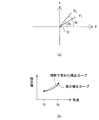
図2(a)は本発明の到来方向推定装置と既知方向の2つの送信源の配置をX−Y平面に示したもので、到来方向推定装置をO点、2つの送信源をP1及びP2に示しており、P1は角度θ1、P2は角度θ2の地点に示している。
【0030】
補正値補間器6では補正値の算出されている隣り合う2方向の角度差(θ2−θ1)が、あらかじめ設定した値よりも小さい場合には、2方向間の補正値を補間計算で算出する。アンテナパタ−ンは、障害物で変化してしまうが、一般的に、角度に対して滑らかな変化をする。したがって、補正値の求まっている角度の値を利用して、補正値の求まっていない角度の値を補間計算で予測することが有効である。補間の方法は、1次補間で求めることができる。
【0031】
補間計算で求めた補正値は図2(b)に示す様に真値とはならない。ところが、補正値の算出されている隣り合う2方向の角度差(θ2−θ1)があらかじめ設定した値よりも小さい場合にのみに補間を行うようにすることに限定させている。そのために、補間計算によって悪い補正値を算出する確率を大幅に減らすことができる。ここで、隣り合う2方向の角度差に対して設定する値は用いるアンテナの種類、配置方法、使用周波数、障害物の種類によってそれぞれ異なる。そこで、前もって、シミュレ−ションや実験を行い決めれば良い。
【0032】
以上説明したように、方向既知の到来電波の受信信号を用いてアンテナパタ−ンの補正値を算出することが可能となる。そして、到来方向推定器3では、補正値保存器5に保存されている補正値を用いて到来方向を推定する。到来方向推定に算出された補正値を用いることで、角度ごとのキャリブレ−ションが可能となるので、精度の良い到来方向推定が可能となる。
【0033】
また、補間計算を用いて補正値を算出しているので、方向既知の到来電波の数が少なくても広い角度にわたって補正値を算出できる利点を有している。
なお、補間の方法は1次補間で求めることができるが、複数の補正値を使用して2次補間で求めることもできるし、他のいかなる方法で求めても良い。また、外挿法を用いて2つの角度間以外の角度の補正値を算出しても良い。
【0034】
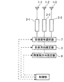
次に、本発明の第2の実施の形態について図面を参照しながら説明する。図3は本発明に係わる到来方向推定装置の構成図である。到来方向推定装置は到来してくる電波を受信する複数のアンテナ素子(1−1〜1−3)と、複数の受信器(2−1〜2−3)と、複数の受信器(2−1〜2−3)の受信信号の中から複数のアンテナ(1−1〜1−3)の近傍に存在する障害物から遠い位置にある複数のアンテナに対応する複数の受信信号を選択する受信信号選択器7と、受信信号選択器7で選択された受信信号を用いて電波の到来方向推定を行う第1の到来方向推定器8−1と、複数の受信器(2−1〜2−3)の受信信号と第1の到来方向推定器8−1で推定された到来方向を用いてその方向のアンテナ振幅パタ−ンの補正値とアンテナ位相パタ−ンの補正値を算出する補正値算出器4と、補正値を保存する補正値保存器5と、補正値保存器で保存された補正値の算出されている2方向の角度差があらかじめ設定した値よりも小さい場合には、2方向間の補正値を補間計算で算出する補正値補間器6と、複数の受信器の受信信号と補正値保存器で保存されている補正値を用いて、電波の到来方向推定を行う第2の到来方向推定器8−2とから構成される。また、これら補正値算出手段4、補正値保存器5、補正値補間器6、受信信号選択器7、第1の到来方向推定器8−1、第2の到来方向推定器8−2は制御部10からの制御信号により動作している。
【0035】
本実施の形態における到来方向推定装置は、到来方向推定装置の近傍に存在する障害物の影響によるアンテナパタ−ンの変化量を補正することが可能であることを特徴とする。また、第1の実施の形態との違いは、到来方向が未知の電波の受信信号を用いて補正することである。
【0036】
以下、本実施の形態の詳細について説明する。なお、第1の実施の形態と同一の部分に関しては、説明を簡略する。
【0037】
到来方向が未知の電波の発信源としては、到来方向推定装置が推定したい電波そのものを用いることができる。したがって、他の送信源を一切必要としないので、どのような到来方向推定装置へも適用することが可能である。
【0038】
本実施の形態においては、到来方向が未知の電波を利用して補正値を算出するが、はじめにその方向を推定してから補正値を算出することを特徴とする。以下に詳細に説明する。
到来方向が未知の電波をアンテナ(1−1〜1−3)が受信し、受信器(2−1〜2−3)から受信信号が出力される。そして、受信信号選択器7によって、そのなかからいくつかの受信信号のみを選択する。
【0039】
ここでは、アンテナ素子(1−1〜1−3)近傍に存在する障害物から物理的な距離が遠い複数のアンテナに対応する受信信号を選択する。例えば、アンテナ素子(1−1〜1−3)の中でアンテナ素子1−1が障害物にもっとも近い位置にある場合には受信器(2−2〜2−3)の受信信号を選択する。
【0040】
アンテナパタ−ンの変化は、障害物からの物理的な距離が小さいほど大きな変化をする。したがって、受信信号選択器で選択される受信信号はアンテナパタ−ンの変化の小さい受信信号のみとなる。
【0041】
そして、第1の到来方向推定器8−1で選択された受信信号を用いて到来方向推定をする。アンテナパタ−ンの変化の小さい素子のみを使用して到来方向推定しているので、精度良く推定することができる。
【0042】
このように、到来方向が未知の電波の到来方向を受信信号選択器7により選択された受信信号と第1の到来方向推定器8−1で精度良く推定することが可能である。そうすると、到来方向が既知となるので、第1の実施の形態と同様に補正値算出器4で補正値を算出し、補正値保存器5で補正値を保存し補正値補間器6で補正値の補間を行う。
そして、第2の到来方向推定器8−2では受信器(2−1〜2−3)からの受信信号と補正値保存器5で保存されている補正値を用いて到来方向を精度良く推定することが可能となる。
以上説明したように、本実施の形態においては、方向未知の電波の受信信号を用いてアンテナパタ−ンをキャリブレ−ションすることが可能となるので、どのような到来方向推定装置へも適用することが可能である。
【0043】
なお、本実施の形態における第1の到来方向推定器で精度の良い到来方向推定が可能となるが、受信信号の選択を行っているので同時に扱える波数が制限される。したがって、補正値を求めて、全ての受信信号を用いて到来方向推定することで同時に扱える波数が増える。したがって、補正値を求めてから到来方向推定を行うことは非常に有効な方法である。
【0044】
次に、本発明の第3の実施の形態について図面を参照しながら説明する。本実施の形態においては、図1に示された到来方向推定装置において補正値保存器5に保存された補正値を用いて障害物の方向を推定する障害物方向推定器を有する到来方向推定装置を提供するものである。
【0045】
アンテナを設置した段階で障害物の方向が分かっていれば問題ないが、地震などの災害によって障害物の方向が変化する場合がある。この場合には、障害物の方向を改めて推定しなおす必要がある。以下、詳細に説明する。
障害物によるアンテナパタ−ンの変化量は、アンテナとの距離と角度によって大小関係が決まる。図4に示すようなアンテナと障害物の関係を用いて説明する。この場合、アンテナ#1が障害物Xから最も大きな影響を受ける。また、アンテナ#1の補正値としては、障害物Xの方向からの電波を用いて到来方向推定を行うと大きな補正値となり、また、障害物Xと反対方向からの電波を用いて到来方向推定を行うと小さな補正値となる。
【0046】
一方、アンテナ#1以外のアンテナ#2#3#4は、小さな補正値となる。したがって、補正値の角度特性を考えると、障害物Xの方向では、素子ごとの補正値に差が大きい。一方、障害物Xとは反対方向では、素子ごとの補正値の差は小さい。
補正値保存器5に保存されている補正値は角度ごとの特性であり、また、相対的な補正値を算出している。したがって、補正値の大きな角度を求めればその方向が概略障害物の方向となる。
【0047】
以上説明したように、補正値保存器5に保存されている補正値の大きな角度から障害物の方向を推定することができる。その結果、障害物の方向が未知の場合でもアンテナパタ−ンを補正することが可能となり、また、精度の良い到来方向推定が可能となる。
【0048】
次に、本発明の第4の実施の形態について図面を参照しながら説明する。本発明の実施の形態においては、方向既知の到来電波の受信信号を用いて、障害物の方向を推定する障害物推定を提供するものである。以下に詳細に説明する。
【0049】
本実施の形態における構成図を図5に示す。この障害物推定装置は到来してくる電波を受信する複数のアンテナ素子(1−1〜1−3)と、複数の受信器(2−1〜2−3)と、この複数の受信器(2−1〜2−3)の受信信号の中から複数のアンテナ(1−1〜1−3)に対応する複数の受信信号を選択する受信信号選択器7と、受信信号選択器7で選択された受信信号を用いて電波の到来方向推定を行う到来方向推定器3、到来方向推定器3からの信号が入力され、この値から障害物方向を推定する障害物方向推定器9 から構成される。また、これら到来方向推定器3、受信信号選択器7、障害物方向推定器9は制御部10からの制御信号により動作している。
【0050】
本実施の形態においては、複数の受信器(2−1〜2−3)からの受信信号の中から任意の複数の受信信号を選択し、その選択された受信信号のみを用いて到来方向推定し、このときの値を障害物方向推定器9に保持をする。さらに、受信信号の選択をかえて複数回到来方向を推定し、それぞれの推定値を障害物方向推定器9に保持する。なお、このときには、補正値を用いないで推定する。
【0051】
到来方向推定を行う場合に、障害物によってアンテナパタ−ンが大きく変化したアンテナの受信信号が含まれている場合、推定誤差が大きくなる。一方、アンテナパタ−ンの変化の小さなアンテナの受信信号のみの場合には、推定誤差は小さい。ここでは、到来方向が既知の電波の受信信号を用いているので、推定誤差の大小を判断することが可能となる。
【0052】
したがって、障害物方向推定器9に保持した推定値を比較検討することにより、パターンが大きく変化しているアンテナを判断することが可能となる。例えば、3素子の場合には、3通りの組み合わせを行い、パタ−ンが大きく変化しているアンテナを判断することが可能となる。ここで、パタ−ンが大きく変化しているアンテナの近傍には障害物があると判断することができる。
【0053】
以上説明したように、到来方向が既知の電波の受信信号を用いた場合には、障害物によって大きなアンテナパタ−ンの変化をしているアンテナを推定することが可能となる。つまり、障害物の方向が推定できることとなる。
【0054】
次に、本発明の第5の実施の形態について説明する。本発明の実施の形態は到来方向推定方法に関するが、補正値の算出されている角度は補正値を用いて到来方向推定を行い、また、補正値の算出されていない角度は、障害物から遠い複数の素子を用いて到来方向推定を行うことを特徴とする。以下に、詳細に説明する。
【0055】
図1に示した到来方向推定装置において到来方向推定装置の設置場所によっては、ある方向からの既知の電波がほとんど存在しない場合がある。このような場合には、その方向の付近の角度で補正値を算出することができないこととなる。このような場合に、どのようにして到来方向推定を行うかが問題となる。
【0056】
これを解決する方法として、まず、補正値の求まっている角度では、補正値を用いて到来方向推定すれば良い。補正値を用いることで、精度の良い推定が可能となる。
【0057】
また、補正値の求まっていない角度は、障害物から遠くにある複数のアンテナを用いて到来方向推定をすることとする。補正値が求まっていないので、障害物に近い素子を用いて到来方向推定すると精度が大幅に劣化してしまう。したがって、アンテナパタ−ンの変化の小さいアンテナのみを用いて到来方向推定を行った方が、精度の良い推定が可能となる。
【0058】
ここでは、アンテナ素子数を減らしているので、同時に推定可能な到来波の数が減ってしまう。到来波数が非常に多い場合には、推定精度は劣化してしまうもののすべての素子を用いて推定することとなる。
【0059】
以上説明したように、本実施の形態によれば補正値が算出されていない角度においても、精度良く到来方向推定が可能な到来方向推定装置を提供することが可能となる。
【0060】
次に、本発明の第6の実施の形態について図面を参照しながら説明する。本発明の実施の形態においては、到来方向が既知または未知の電波を用いて、また、障害物の方向が既知または未知の場合に、補正値を算出することが可能な到来方向推定装置である。
図6に本実施の形態における到来方向推定装置を示す。また、図7に、補正値を算出するための処理の流れを示すフロ−チャ−トを示す。
【0061】
図6に示すように、本発明の到来方向推定装置は到来してくる電波を受信する複数のアンテナ素子(1−1〜1−3)と、複数の受信器(2−1〜2−3)と、複数の受信器(2−1〜2−3)の受信信号の中から、複数のアンテナ(1−1〜1−3)の近傍に存在する障害物から遠い位置にある複数のアンテナに対応する複数の受信信号を選択する受信信号選択器7と、受信信号選択器7で選択された受信信号を用いて電波の到来方向推定を行う第1の到来方向推定器8−1と、複数の受信器(2−1〜2−3)の受信信号と第1の到来方向推定器8−1で推定された到来方向を用いて、その方向のアンテナ振幅パタ−ンの補正値とアンテナ位相パタ−ンの補正値を算出する補正値算出器4と、補正値を保存する補正値保存器5と、補正値保存器で保存された補正値の算出されている2方向の角度差があらかじめ設定した値よりも小さい場合には、2方向間の補正値を補間計算で算出する補正値補間器6と、複数の受信器の受信信号と補正値保存器で保存されている補正値を用いて、電波の到来方向推定を行う第2の到来方向推定器8−2とから構成される。また、第1の到来方向推定器8−1からの出力は障害物方向推定器9に供給される。さらに、これら補正値算出手段4、補正値保存器5、補正値補間器6、受信信号選択器7、第1の到来方向推定器8−1、第2の到来方向推定器8−2及び障害物方向推定器は制御部10からの制御信号により動作している。
【0062】
次に、図7に示すフロ−チャ−トをもとに本発明の到来方向推定装置の動作を説明する。
【0063】
はじめに到来してくる電波を複数のアンテナ素子(1−1〜1−3)で受信し(STEP1)、この到来電波が既知かどうかを判定する(STEP2)。
【0064】
到来電波が既知の場合は既知の方向からの到来波を用いて、補正値算出器4で補正値を計算する(STEP3)。さらに補間値補間器6で補正値の補間を計算した後(STEP4)、補間値補間器で補間した補正値を保管する(STEP5)。そして、この補間値を用いて第2の到来方向推定器8−2でキャリブレ−ションを行った到来方向推定を行うことができる。
【0065】
また、STEP2において到来電波の方向が未知の場合は、障害物の方向が既知かどうかを判断(STEP6)し、障害物の方向が既知の場合は、受信選択器7によりこの障害物に遠い複数のアンテナで受信信号された信号を用い第1の到来方向推定器8−1により到来電波の到来方向を推定する(STEP7)。到来方向が推定されたなら、STEP3〜STEP5の動作により補正値を保管し、この補間値を用いて第2の到来方向推定器8−2でキャリブレ−ションを行った到来方向推定を行うことができる。
【0066】
また、STEP2において到来電波の方向が未知で、STEP6において障害物の方向も未知の場合にははじめに障害物方向推定器9により障害物方向を推定し(STEP8)、次に到来電波の方向を推定した(STEP7)後、STEP3〜STEP5の動作により補正値を保管し、この補間値を用いて第2の到来方向推定器8−2でキャリブレ−ションを行った到来方向推定を行うことができる。
【0067】
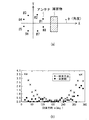
ここで、実際に数値シミュレ−ションを用いて、本発明の効果を定量的に評価した結果を以下に示す。図8(a)に評価する上で用いたアンテナ及び障害物の配置関係をX−Y座標で示す。8素子の円形アレイアンテナを用い、その近傍に立方体の障害物がある場合で検討を行った。アンテナはモノポ−ルアンテナを用い、障害物は金属製で、アンテナと同じ高さとしている。この障害物の影響で、アンテナパタ−ンが変化することを想定した。なお、障害物の影響を含めたアンテナ特性は電磁界解析シミュレ−ションのひとつであるモ−メント法を用いて計算している。
【0068】
到来方向は水平面内のみとし、また、周波数は単一周波数で実施している。ここで、方向既知の到来波として、(5、15、35、45、65、75、95、185、215、245、275°)の合計11方向からの到来波を用い、方向未知の到来波として、(125、155°)の合計2方向からの到来波を用いた。また、補間を行う場合の2方向の最小角度差を35°と設定している。
その結果、5°〜275°の範囲に補正値を算出することが可能となった。つまり、5〜275°の範囲は補正値を用いて到来方向推定を行い、275〜360°の範囲は、障害物から遠い位置にあるアンテナ素子の受信信号を用いて到来方向推定を行う。今回は、アンテナ#3#4#5#6の4素子を用いた。
【0069】
図8(b)は、方向推定アルゴリズムにMUSICを用いた場合の推定精度を示す。図8(b)の横軸は到来波の到来角度、縦軸は、そのときの推定誤差の絶対値である。×印が、本発明を用いないで通常のMUSIC法で推定した場合の結果、●が本発明で行った場合の結果である。
【0070】
図8(b)より、本発明によって、推定精度が大幅に改善していることが分かる。特に、障害物のある方向では推定精度の改善が大きく本発明が極めて有効であるといえる。
【0071】
以上説明したように本発明によれば、障害物の影響によって到来方向推定精度が大幅に劣化した場合でも、補正値を広い角度範囲にわたり算出することが可能であり、また、精度の良い推定が可能であることが分かる。
【0072】
以上の説明では、到来波の周波数に関して述べていなかったが、周波数帯域幅の非常に広い場合には以下のように取り扱えば良い。まず、周波数帯域幅が広いと周波数によって、障害物からの影響の受け方が異なる。したがって、周波数を複数に分割しそれぞれの周波数に対して補正値を算出すれば良い。
【0073】
また、補正値の補間はある周波数に対して2つの角度の間で計算することとある角度に対して2つの周波数の間で計算することが有効である。なぜならば、一般に、角度と周波数に対し滑らかに特性が変化するからである。このようにすると、補正値を算出するための到来波の数が少ない場合でも、広い角度範囲、そして、広い周波数範囲において補正値を算出することが可能となる。
【0074】
さらに、2次元(Az、El)の方向推定を行う場合がある。この場合にも、2方向間の補間計算を行うことで広い角度範囲で補正値を算出することが可能となる。
【0075】
さらに、2次元(Az、El)の方向推定で周波数帯域幅が広い場合がある。この場合には、周波数帯域幅を複数に分割し、また、方向と周波数の両方で補間計算を行うことで、広い角度範囲、そして、広い周波数範囲で補正値を計算することが可能となる。
【0076】
また、本発明の補正値補間器6では、補正値が算出される毎に、補間計算を再び行い、補正値を再計算することで精度の良い補正値が得られる。なぜならば、補正値の得られる角度の数が増えるにつれて2つの方向の角度差が小さくなり、補間精度の向上が期待できるからである。したがって、装置の運用を長い間行うことで補正値の精度は向上していく。つまり、本発明を用いることで、長い間同じ装置を使用することが可能になり、低コストで装置を維持することが可能となる。
【0077】
また、本発明の補正値算出器4、および、到来方向推定器(3,8−1,8−2)をデジタル信号処理で実施することで、これを一つの処理装置で実行することもできる。この場合には、機器の小型化や、省電力化も可能となり、また、アルゴリズムの変更もソフトウエアの入れ替えだけで済むので、簡易となり有効な方法であるといえる。
【0078】
また、本発明をアダプティブアンテナへ適用することも可能である。通信に用いるアダプティブアンテナでは、通信相手へパタ−ンのビ−ムを向けたり、逆に、通信相手以外へパタ−ンのヌルを向けたりする。このときに、アンテナパタ−ンが付近の障害物によって変化してしまった場合には、精確にビ−ムを向けたり、ヌルを向けたりすることができなくなる。そこで、本発明を用いて、アンテナパタ−ンのキャリブレ−ションを行うことで、アダプティブアンテナの性能を大幅に向上することが可能となる。
【0079】
【発明の効果】
本発明の到来方向推定装置では、アンテナの放射パタ−ンが、アンテナ近傍の障害物によって変化してしまった場合でも、到来方向が既知または未知の電波の受信信号を用いて、補正値を算出し、あるいは、補間計算により補正値を算出しキャリブレ−ションすることが可能となり、高精度な到来方向推定が可能となる。
【図面の簡単な説明】
【図1】本発明の第1の実施の形態に係る到来方向推定装置
【図2】本発明の補間計算の求め方を表わす図
【図3】本発明の他の実施の形態に係る到来方向推定装置
【図4】障害物によるアンテナパタ−ンの変化量を説明するための図
【図5】本発明の他の実施の形態に係る到来方向推定装置
【図6】本発明の他の実施の形態に係る到来方向推定装置
【図7】本発明の他の実施の形態に係る到来方向推定装置の動作を示すフロ−チャ−ト
【図8】本発明の実施の形態に係る到来方向推定装置の到来方向推定精度を表わす図
【符号の説明】
1−1〜1−3・・・・・アンテナ
2−1〜2−3・・・・・受信器
3・・・・・・・・・到来方向推定器
4・・・・・・・・・補正値算出器
5・・・・・・・・・補正値保存器
6・・・・・・・・・補正値補間器
7・・・・・・・・・受信信号選択器
8−1・・・・・・・・第1の到来方向推定器
8−2・・・・・・・・第2の到来方向推定器
9・・・・・・・・・障害物方向推定器
10・・・・・・・・制御器[0001]
BACKGROUND OF THE INVENTION
The present invention relates to an arrival wave direction estimation device used in a mobile communication base station, a radio wave monitoring device, a radar device, and the like.
[0002]
[Prior art]
In mobile communication base stations, radio wave monitoring devices, and radar devices, an arrival direction estimation device that accurately estimates the direction of incoming radio waves is desired.
[0003]
As a method of estimating the direction of arrival with high accuracy, MUSIC (Multiple Signal Classification) (R. O. Schmitt, “Multiple Emitter Location and Signal Parameter Estimation”, IEEE Trans. vol. AP-34, no. 3, pp. 276-280, March, 1986.).
[0004]
This arrival direction estimation apparatus using MUSIC includes a plurality of antennas, a plurality of receivers respectively connected to the plurality of antennas, and arrival direction estimation means connected to the plurality of receivers. The arrival direction estimation means estimates the arrival direction using the received signals from all antennas and the antenna pattern (amplitude and phase) used.
[0005]
Calibration of the antenna and the receiver is important for accurately estimating the direction of arrival using MUSIC. If the calibration is incomplete, the estimation error in the direction of arrival becomes large and the accuracy is greatly deteriorated.
[0006]
The calibration method of the antenna and the receiver is shown in “Adaptive Antenna Calibration Method” of Japanese Patent Application Laid-Open No. 2001-217760. An adaptive antenna has a function of estimating the direction of arrival and directing the beam in that direction, and therefore includes an arrival direction estimation device.
[0007]
In this calibration method, a transmission device is installed in a known direction, and a transmission wave from the transmission device is received by a plurality of antennas provided in the arrival direction estimation device. This received signal passes through an analog receiver and an A / D converter provided in the direction-of-arrival estimation device, and is converted into a digital signal. If the direction of the transmission device and the arrangement of the plurality of antennas as seen from the direction of arrival estimation device are known and the characteristics of the plurality of analog receivers of the direction of arrival estimation device are the same, the phase difference of the digital signal is a predetermined value. In addition, the amplitude becomes a predetermined value.
[0008]
However, since antennas and analog receivers generally vary, the amplitude and phase do not become predetermined values. Therefore, a calibration value for setting the amplitude and phase to desired values is calculated. By multiplying this by the digital received signal, calibration can be performed.
[0009]
However, the above-described method is used in the case where obstacles that scatter and absorb radio waves such as signs and pillars, which are not expected at the design stage, exist near the antenna, and the antenna pattern changes depending on the angle. It becomes impossible to calibrate. This is because, since the transmitting apparatus is only in a specific direction, only the calibration value in that direction can be obtained. In particular, when an obstacle exists in the vicinity of the arrival direction estimation device at the time of a disaster such as an earthquake, there is a possibility that it becomes a big problem.
[0010]
Also, when the direction of arrival is estimated using MUSIC, the direction of arrival is estimated using the amplitude and phase pattern of the antenna, and therefore the estimation accuracy is degraded if calibration of the antenna pattern is not possible. It becomes a big problem.
[0011]
As a solution method in such a case, it is only necessary to arrange transmitters in all directions and obtain calibration values in all directions. However, placing transmitters in all directions has a significant cost problem and is not practical.
[0012]
As another method, there is a method of clarifying the influence of a signboard, a pillar, etc. by numerical simulation. However, even in this case, there is a possibility that the signboard shape changes, the position changes, or the electrical medium constant changes after the arrival direction estimation device is installed.
In addition, when an obstacle has a complicated shape, numerical simulation may not be performed.
[0013]
As described above, the calibration method in the conventional direction-of-arrival estimation apparatus cannot be applied when the antenna pattern itself has changed due to an obstacle. . In addition, it is possible to quantitatively evaluate the influence of obstacles by numerical simulation, but it can be applied because it is an obstacle with a simple structure and can be applied only when it does not change over time. However, there was a problem that was extremely limited.
[0014]
[Problems to be solved by the invention]
As described above, the calibration method in the conventional direction-of-arrival estimation apparatus can calibrate without an angular characteristic, but cannot calibrate an antenna pattern having an angular characteristic. There was a problem.
[0015]
The present invention has been made in view of such conventional problems, and provides an arrival direction estimation device that enables calibration of an antenna pattern and can estimate the arrival direction with high accuracy. Objective.
[0016]
[Means for Solving the Problems]
An arrival direction estimation apparatus and an arrival direction estimation method of the present invention for solving the above problems are as follows.
A radio wave having a known direction of arrival is received, and using these received signals, an antenna amplitude pattern correction value and an antenna phase pattern correction value for the known radio wave are calculated, and the calculated correction value is also obtained. When the angular difference in two directions of the plurality of known radio waves for which the correction values are calculated is smaller than a preset value, an interpolation correction value between the two directions is calculated by interpolation calculation, and these interpolation correction values, The direction of arrival of radio waves is estimated using the calculated correction value and the received signal.
[0019]
DETAILED DESCRIPTION OF THE INVENTION
Hereinafter, a first embodiment of the present invention will be described with reference to the drawings. FIG. 1 is a block diagram of an arrival direction estimating apparatus according to the present invention. The arrival direction estimation device includes a plurality of antenna elements (1-1 to 1-3) that receive incoming radio waves, and a plurality of receivers (2) connected to the antenna elements (1-1 to 1-3), respectively. −1 to 2-3) and a correction value calculation means for calculating the correction value of the antenna amplitude pattern and the correction value of the antenna phase pattern in the direction using the received signal of the radio wave whose arrival direction is known 4 and a
[0020]
The direction-of-arrival estimation apparatus according to the present embodiment is capable of correcting an amount of change in antenna pattern due to the influence of an obstacle that cannot be predicted at the design stage existing in the vicinity of the direction-of-arrival estimation apparatus. . Hereinafter, details of the present embodiment will be described. In the description here, three antenna elements are used for easy understanding.
Any antenna element (1-1 to 1-3) may be used as long as it is designed to receive incoming radio waves. A wide beam dipole antenna or a narrow beam Yagi / Uda antenna may be used. The plurality of antenna arrangements may be any arrangement. It may be a linear array, a circular array, or a rectangular array.
[0021]
The receiver (2-1 to 2-3) converts the signal received by the antenna into a received signal whose arrival direction can be estimated by a subsequent arrival direction estimator. For example, it is composed of an amplifier, a frequency converter, a filter, an A / D converter, and the like.
[0022]
Then, the arrival direction is estimated by the
[0023]
Here, there may be an obstacle that cannot be predicted at the design stage such as a signboard or a pillar in the vicinity of the antenna elements (1-1 to 1-3). In this case, the amplitude pattern of the antenna and the phase pattern of the antenna change differently for each angle. As a result, the arrival direction estimation accuracy is greatly deteriorated. Therefore, the correction value of the antenna pattern is calculated by the following procedure.
[0024]
Here, a method of calculating a correction value using a reception signal of radio waves coming from a known direction is used. A radio wave transmission source from a known direction may be any device that is a fixed location and transmits radio waves, such as a mobile communication base station and a broadcast wave transmission station. . Alternatively, a transmission device may be installed at an appropriate place and transmitted from there. That is, any radio wave may be used as long as it is an incoming wave whose direction can be specified.
[0025]
A correction value is calculated by the
[0026]
However, when the antenna pattern has changed due to an obstacle, the received signal changes from the value calculated using the designed radiation pattern. For this reason, the amplitude difference and the phase difference between the received signals vary from the design values. Here, the amount of change from the design value corresponds to the amount of change in the amplitude and phase of the antenna. Therefore, this can be used as a correction value.
[0027]
As described above, by using a received signal in a known direction of arrival, it is possible to obtain correction values for the amplitude and phase of the antenna pattern in that direction. The correction value is stored in the
[0028]
However, this correction value can be obtained only in the direction of the radio wave transmission source whose direction is known. Therefore, the
[0029]
FIG. 2A shows the arrangement of the arrival direction estimation apparatus of the present invention and two transmission sources in a known direction on the XY plane. The arrival direction estimation apparatus is at point O, and the two transmission sources are P1 and P2. P1 is the angle θ1, and P2 is the point of the angle θ2.
[0030]
In the
[0031]
The correction value obtained by the interpolation calculation is not a true value as shown in FIG. However, the interpolation is performed only when the angle difference (θ2−θ1) between two adjacent directions where the correction value is calculated is smaller than a preset value. Therefore, the probability of calculating a bad correction value by interpolation calculation can be greatly reduced. Here, the values set for the angle difference between two adjacent directions differ depending on the type of antenna used, the arrangement method, the frequency used, and the type of obstacle. Therefore, it is only necessary to decide in advance through simulations and experiments.
[0032]
As described above, the correction value of the antenna pattern can be calculated using the received signal of the incoming radio wave whose direction is known. Then, the
[0033]
In addition, since the correction value is calculated using interpolation calculation, there is an advantage that the correction value can be calculated over a wide angle even if the number of incoming radio waves whose directions are known is small.
Although the interpolation method can be obtained by primary interpolation, it can also be obtained by secondary interpolation using a plurality of correction values, or any other method. Moreover, you may calculate the correction value of angles other than between two angles using an extrapolation method.
[0034]
Next, a second embodiment of the present invention will be described with reference to the drawings. FIG. 3 is a block diagram of an arrival direction estimating apparatus according to the present invention. The arrival direction estimation device includes a plurality of antenna elements (1-1 to 1-3) that receive incoming radio waves, a plurality of receivers (2-1 to 2-3), and a plurality of receivers (2- Reception for selecting a plurality of received signals corresponding to a plurality of antennas located at a position far from an obstacle existing in the vicinity of the plurality of antennas (1-1 to 1-3) from the received signals of 1 to 2-3) A
[0035]
The arrival direction estimation apparatus according to the present embodiment is characterized in that it can correct the amount of change in the antenna pattern due to the influence of an obstacle present in the vicinity of the arrival direction estimation apparatus. The difference from the first embodiment is that correction is performed using a received signal of a radio wave whose direction of arrival is unknown.
[0036]
Hereinafter, details of the present embodiment will be described. The description of the same parts as those in the first embodiment will be simplified.
[0037]
As a transmission source of a radio wave whose arrival direction is unknown, the radio wave itself that the arrival direction estimation apparatus wants to estimate can be used. Accordingly, since no other transmission source is required, the present invention can be applied to any arrival direction estimation device.
[0038]
In the present embodiment, the correction value is calculated using a radio wave whose arrival direction is unknown. However, the correction value is calculated after first estimating the direction. This will be described in detail below.
The antennas (1-1 to 1-3) receive radio waves whose directions of arrival are unknown, and reception signals are output from the receivers (2-1 to 2-3). Then, the
[0039]
Here, received signals corresponding to a plurality of antennas that are physically distant from an obstacle existing in the vicinity of the antenna elements (1-1 to 1-3) are selected. For example, when the antenna element 1-1 is located closest to the obstacle among the antenna elements (1-1 to 1-3), the reception signal of the receiver (2-2 to 2-3) is selected. .
[0040]
The antenna pattern changes more greatly as the physical distance from the obstacle is smaller. Therefore, the received signal selected by the received signal selector is only a received signal with a small change in antenna pattern.
[0041]
Then, the arrival direction is estimated using the received signal selected by the first arrival direction estimator 8-1. Antenna pattern Small change element Since the direction of arrival is estimated using only, it is possible to estimate with high accuracy.
[0042]
In this way, it is possible to accurately estimate the arrival direction of a radio wave whose arrival direction is unknown by the reception signal selected by the
Then, the second arrival direction estimator 8-2 accurately estimates the arrival direction using the received signal from the receiver (2-1 to 2-3) and the correction value stored in the
As described above, in the present embodiment, the antenna pattern can be calibrated using the received signal of the radio wave of unknown direction, so that the present invention can be applied to any arrival direction estimation device. It is possible.
[0043]
Although the first arrival direction estimator in the present embodiment can perform arrival direction estimation with high accuracy, the number of waves that can be handled simultaneously is limited because reception signals are selected. Therefore, by obtaining the correction value and estimating the direction of arrival using all the received signals, the number of waves that can be handled simultaneously increases. Therefore, it is a very effective method to estimate the direction of arrival after obtaining the correction value.
[0044]
Next, a third embodiment of the present invention will be described with reference to the drawings. In the present embodiment, the arrival direction estimation apparatus having the obstacle direction estimator that estimates the direction of the obstacle using the correction value stored in the
[0045]
If the direction of the obstacle is known at the stage of installing the antenna, there is no problem, but the direction of the obstacle may change due to a disaster such as an earthquake. In this case, it is necessary to re-estimate the direction of the obstacle. Details will be described below.
The amount of change in the antenna pattern due to the obstacle is determined by the distance and angle with the antenna. This will be described using the relationship between the antenna and the obstacle as shown in FIG. In this case, the
[0046]
On the other hand,
The correction value stored in the
[0047]
As described above, the direction of the obstacle can be estimated from the large angle of the correction value stored in the
[0048]
Next, a fourth embodiment of the present invention will be described with reference to the drawings. The embodiment of the present invention provides obstacle estimation for estimating the direction of an obstacle using a received signal of an incoming radio wave whose direction is known. This will be described in detail below.
[0049]
FIG. 5 shows a configuration diagram in the present embodiment. The obstacle estimation apparatus includes a plurality of antenna elements (1-1 to 1-3) that receive incoming radio waves, a plurality of receivers (2-1 to 2-3), and a plurality of receivers ( The
[0050]
In the present embodiment, an arbitrary plurality of received signals are selected from the received signals from the plurality of receivers (2-1 to 2-3), and the direction of arrival is estimated using only the selected received signals. The value at this time is held in the
[0051]
When the direction of arrival is estimated, if the received signal of the antenna whose antenna pattern has changed greatly due to an obstacle is included, the estimation error becomes large. On the other hand, the estimation error is small when only the received signal of the antenna with a small change in the antenna pattern is used. Here, since the received signal of the radio wave whose arrival direction is known is used, it is possible to determine the magnitude of the estimation error.
[0052]
Therefore, by comparing the estimated values held in the
[0053]
As described above, when a received signal of a radio wave whose direction of arrival is known is used, it is possible to estimate an antenna that has a large antenna pattern change due to an obstacle. That is, the direction of the obstacle can be estimated.
[0054]
Next, a fifth embodiment of the present invention will be described. Although the embodiment of the present invention relates to an arrival direction estimation method, the angle for which the correction value is calculated is estimated using the correction value, and the angle for which the correction value is not calculated is far from the obstacle. The direction of arrival is estimated using a plurality of elements. This will be described in detail below.
[0055]
In the arrival direction estimation apparatus shown in FIG. 1, there may be almost no known radio waves from a certain direction depending on the installation location of the arrival direction estimation apparatus. In such a case, the correction value cannot be calculated at an angle near that direction. In such a case, how to estimate the direction of arrival is a problem.
[0056]
As a method for solving this, first, the direction of arrival may be estimated using the correction value at the angle at which the correction value is obtained. By using the correction value, accurate estimation can be performed.
[0057]
In addition, for the angle for which the correction value is not obtained, the direction of arrival is estimated using a plurality of antennas far from the obstacle. Since the correction value has not been obtained, the accuracy is greatly degraded if the direction of arrival is estimated using an element close to the obstacle. Therefore, more accurate estimation is possible when direction of arrival estimation is performed using only antennas whose change in antenna pattern is small.
[0058]
Here, since the number of antenna elements is reduced, the number of incoming waves that can be estimated simultaneously is reduced. When the number of incoming waves is very large, the estimation accuracy is degraded, but estimation is performed using all elements.
[0059]
As described above, according to the present embodiment, it is possible to provide an arrival direction estimation device that can accurately estimate the arrival direction even at an angle for which no correction value is calculated.
[0060]
Next, a sixth embodiment of the present invention will be described with reference to the drawings. In an embodiment of the present invention, an arrival direction estimation apparatus capable of calculating a correction value using a radio wave whose arrival direction is known or unknown and when the direction of an obstacle is known or unknown .
FIG. 6 shows an arrival direction estimation apparatus in the present embodiment. FIG. 7 is a flowchart showing the flow of processing for calculating a correction value.
[0061]
As shown in FIG. 6, the arrival direction estimating apparatus of the present invention includes a plurality of antenna elements (1-1 to 1-3) that receive incoming radio waves and a plurality of receivers (2-1 to 2-3). ) And a plurality of antennas located at a position far from an obstacle existing in the vicinity of the plurality of antennas (1-1 to 1-3) from the reception signals of the plurality of receivers (2-1 to 2-3) A
[0062]
Next, the operation of the direction-of-arrival estimation apparatus according to the present invention will be described based on the flowchart shown in FIG.
[0063]
First, the incoming radio waves are received by a plurality of antenna elements (1-1 to 1-3) (STEP 1), and it is determined whether or not the incoming radio waves are known (STEP 2).
[0064]
When the incoming radio wave is known, the correction value is calculated by the
[0065]
If the direction of the incoming radio wave is unknown in
[0066]
If the direction of the incoming radio wave is unknown in
[0067]
Here, the results of quantitative evaluation of the effects of the present invention using actual numerical simulation are shown below. FIG. 8A shows the arrangement relationship between the antenna and the obstacle used in the evaluation with XY coordinates. The study was conducted using an 8-element circular array antenna and a cubic obstacle nearby. The antenna is a monopole antenna, and the obstacle is made of metal and has the same height as the antenna. It is assumed that the antenna pattern changes due to this obstacle. The antenna characteristics including the influence of obstacles are calculated using a moment method, which is one of electromagnetic field analysis simulations.
[0068]
The direction of arrival is only in the horizontal plane, and the frequency is a single frequency. Here, as arriving waves with known directions, arriving waves from a total of 11 directions (5, 15, 35, 45, 65, 75, 95, 185, 215, 245, 275 °) are used, and arriving waves with unknown directions are used. As a result, arriving waves from a total of two directions (125, 155 °) were used. Further, the minimum angle difference between the two directions when performing interpolation is set to 35 °.
As a result, the correction value can be calculated in the range of 5 ° to 275 °. That is, the direction of arrival is estimated using the correction value in the range of 5 to 275 °, and the direction of arrival is estimated using the received signal of the antenna element located far from the obstacle in the range of 275 to 360 °. This time, four elements of
[0069]
FIG. 8B shows the estimation accuracy when MUSIC is used as the direction estimation algorithm. The horizontal axis of FIG. 8B is the arrival angle of the incoming wave, and the vertical axis is the absolute value of the estimation error at that time. A cross indicates a result obtained by estimation using a normal MUSIC method without using the present invention, and a black circle indicates a result obtained by performing the present invention.
[0070]
FIG. 8 (b) shows that the estimation accuracy is greatly improved by the present invention. In particular, it can be said that the present invention is extremely effective in the direction where the obstacle is present because the estimation accuracy is greatly improved.
[0071]
As described above, according to the present invention, it is possible to calculate the correction value over a wide angle range even when the arrival direction estimation accuracy is significantly deteriorated due to the influence of the obstacle, and accurate estimation is possible. It turns out that it is possible.
[0072]
In the above description, the frequency of the incoming wave has not been described. However, when the frequency bandwidth is very wide, it may be handled as follows. First, when the frequency bandwidth is wide, the influence from the obstacle differs depending on the frequency. Therefore, the correction value may be calculated for each frequency by dividing the frequency into a plurality of frequencies.
[0073]
It is also effective to calculate the correction value between two frequencies for a certain frequency and between two frequencies for a certain angle. This is because the characteristics generally change smoothly with respect to angle and frequency. In this way, even when the number of incoming waves for calculating the correction value is small, the correction value can be calculated in a wide angle range and a wide frequency range.
[0074]
Furthermore, there are cases where two-dimensional (Az, El) direction estimation is performed. Also in this case, it is possible to calculate a correction value in a wide angle range by performing interpolation calculation between two directions.
[0075]
Furthermore, there are cases where the frequency bandwidth is wide in two-dimensional (Az, El) direction estimation. In this case, the correction value can be calculated in a wide angular range and a wide frequency range by dividing the frequency bandwidth into a plurality of parts and performing interpolation calculation in both the direction and the frequency.
[0076]
In addition, the
[0077]
Further, the
[0078]
It is also possible to apply the present invention to an adaptive antenna. In an adaptive antenna used for communication, a pattern beam is directed to a communication partner, or conversely, a pattern null is directed to a party other than the communication partner. At this time, if the antenna pattern has been changed by a nearby obstacle, the beam or the null cannot be directed accurately. Therefore, by performing calibration of the antenna pattern using the present invention, it becomes possible to greatly improve the performance of the adaptive antenna.
[0079]
【The invention's effect】
In the arrival direction estimation apparatus of the present invention, even when the radiation pattern of the antenna is changed by an obstacle near the antenna, the correction value is calculated using the received signal of the radio wave whose arrival direction is known or unknown. Alternatively, the correction value can be calculated by the interpolation calculation and calibrated, and the arrival direction can be estimated with high accuracy.
[Brief description of the drawings]
FIG. 1 is an arrival direction estimation apparatus according to a first embodiment of the present invention;
FIG. 2 is a diagram showing how to calculate interpolation calculation according to the present invention.
FIG. 3 is an arrival direction estimation apparatus according to another embodiment of the present invention.
FIG. 4 is a diagram for explaining a change amount of an antenna pattern due to an obstacle;
FIG. 5 is an arrival direction estimation apparatus according to another embodiment of the present invention.
FIG. 6 is an arrival direction estimation apparatus according to another embodiment of the present invention.
FIG. 7 is a flowchart showing the operation of an arrival direction estimating apparatus according to another embodiment of the present invention.
FIG. 8 is a diagram representing the arrival direction estimation accuracy of the arrival direction estimation apparatus according to the embodiment of the present invention.
[Explanation of symbols]
1-1 to 1-3 ... Antenna
2-1 to 2-3 ... receiver
3 ..... Arrival direction estimator
4 ..... Correction value calculator
5 ... Correction value storage
6 ..... Correction value interpolator
7 ・ ・ ・ ・ ・ ・ ・ ・ ・ Receiver signal selector
8-1 ・ ・ ・ First direction of arrival estimator
8-2 Second direction of arrival estimator
9 .... Obstacle direction estimator
10 ... Controller
Claims (5)
前記複数のアンテナ素子のそれぞれに対応して接続した複数の受信器と、
到来方向が既知の電波を受信し、前記複数の受信器からの受信信号を用いて、前記既知の電波に対するアンテナ振幅パターンの補正値とアンテナ位相パターンの補正値をそれぞれ算出する補正値算出手段と、
前記複数の補正値を保存する補正値保存手段と、
前記補正値保存手段で保存された補正値を算出した前記複数の既知の電波の2方向の角度差が、あらかじめ設定した値よりも小さい場合に2方向間の補間補正値を補間計算で算出するとともに、これら補間補正値を前記補正値保存手段に供給する補正値補間手段と、
前記複数の受信器の受信信号と前記補正値保存手段で保存されている補正値を用いて、電波の到来方向推定を行う到来方向推定手段と
を具備することを特徴とする到来方向推定装置。A plurality of antenna elements for receiving incoming radio waves;
A plurality of receivers connected corresponding to each of the plurality of antenna elements;
Correction value calculating means for receiving radio waves whose directions of arrival are known, and using the received signals from the plurality of receivers, respectively, calculating correction values for antenna amplitude patterns and antenna phase patterns for the known radio waves; ,
Correction value storage means for storing the plurality of correction values;
When an angle difference between the two directions of the plurality of known radio waves for which the correction value stored by the correction value storage unit is calculated is smaller than a preset value, an interpolation correction value between the two directions is calculated by interpolation calculation. A correction value interpolation means for supplying these interpolation correction values to the correction value storage means,
An arrival direction estimation device comprising arrival direction estimation means for estimating an arrival direction of radio waves using received signals of the plurality of receivers and correction values stored in the correction value storage means.
Priority Applications (1)
| Application Number | Priority Date | Filing Date | Title |
|---|---|---|---|
| JP2002168150A JP4014941B2 (en) | 2002-06-10 | 2002-06-10 | Arrival direction estimation apparatus and arrival direction estimation method |
Applications Claiming Priority (1)
| Application Number | Priority Date | Filing Date | Title |
|---|---|---|---|
| JP2002168150A JP4014941B2 (en) | 2002-06-10 | 2002-06-10 | Arrival direction estimation apparatus and arrival direction estimation method |
Related Child Applications (1)
| Application Number | Title | Priority Date | Filing Date |
|---|---|---|---|
| JP2007196233A Division JP4015180B2 (en) | 2007-07-27 | 2007-07-27 | Arrival direction estimation apparatus, arrival direction estimation method, and obstacle estimation apparatus |
Publications (2)
| Publication Number | Publication Date |
|---|---|
| JP2004012362A JP2004012362A (en) | 2004-01-15 |
| JP4014941B2 true JP4014941B2 (en) | 2007-11-28 |
Family
ID=30435136
Family Applications (1)
| Application Number | Title | Priority Date | Filing Date |
|---|---|---|---|
| JP2002168150A Expired - Fee Related JP4014941B2 (en) | 2002-06-10 | 2002-06-10 | Arrival direction estimation apparatus and arrival direction estimation method |
Country Status (1)
| Country | Link |
|---|---|
| JP (1) | JP4014941B2 (en) |
Families Citing this family (8)
| Publication number | Priority date | Publication date | Assignee | Title |
|---|---|---|---|---|
| KR100757113B1 (en) * | 2005-08-11 | 2007-09-10 | 삼성탈레스 주식회사 | Apparatus for the calibrating the amplitude and phase in directional finder |
| JP4173882B2 (en) * | 2005-09-06 | 2008-10-29 | 日本電業工作株式会社 | Arrival direction estimation method |
| JP4787298B2 (en) | 2008-08-01 | 2011-10-05 | 株式会社日本自動車部品総合研究所 | Ultrasonic object orientation detector |
| KR101032299B1 (en) | 2011-01-03 | 2011-05-06 | 삼성탈레스 주식회사 | Self-calibration for direction finding in multi-baseline interferometer system |
| KR101498615B1 (en) | 2014-03-20 | 2015-03-04 | 한국전자통신연구원 | Apparatus and method for estimating direction of relaying radio signal |
| RU2603971C1 (en) * | 2015-07-07 | 2016-12-10 | Федеральное Государственное Унитарное Предприятие Ордена Трудового Красного Знамени Научно-Исследовательский Институт Радио (Фгуп Ниир) | Method of measuring angles in phase multi-scale angular systems and device therefor |
| JP6672846B2 (en) | 2016-02-03 | 2020-03-25 | 富士通株式会社 | Wireless device and phase control method |
| KR20220016735A (en) * | 2020-08-03 | 2022-02-10 | 삼성전자주식회사 | Method for measuring location using wireless communication and electronic device supporting the same |
-
2002
- 2002-06-10 JP JP2002168150A patent/JP4014941B2/en not_active Expired - Fee Related
Also Published As
| Publication number | Publication date |
|---|---|
| JP2004012362A (en) | 2004-01-15 |
Similar Documents
| Publication | Publication Date | Title |
|---|---|---|
| US11824272B2 (en) | In-field millimeter-wave phased array radiation pattern estimation and validation | |
| JP4227009B2 (en) | Positioning system, positioning method and positioning server | |
| JP5612257B2 (en) | Multi-antenna measurement method and multi-antenna measurement system | |
| US10348381B2 (en) | Antenna system configuration | |
| JP4015180B2 (en) | Arrival direction estimation apparatus, arrival direction estimation method, and obstacle estimation apparatus | |
| CN106712864B (en) | Method and device for testing and optimizing performance of intelligent antenna | |
| US11714155B2 (en) | Method for finding signal direction using modal antenna | |
| JP4014941B2 (en) | Arrival direction estimation apparatus and arrival direction estimation method | |
| US10531465B2 (en) | Communication device, access node and methods thereof | |
| JP2009236707A (en) | Signal source position estimation method | |
| CN102833848B (en) | Method, device and system for positioning mobile station | |
| JP4014981B2 (en) | Arrival direction estimation apparatus and arrival direction estimation method | |
| JP2004147079A (en) | Radio system | |
| Liao et al. | A beam switching array antenna for direction‐of‐arrival applications | |
| JP2018004609A (en) | Position measuring method of radio communication terminal and radio device | |
| JP6628596B2 (en) | Array antenna device and wireless device | |
| JP3640891B2 (en) | Arrival wave direction estimation apparatus and arrival wave direction estimation method | |
| CN113630720A (en) | Indoor positioning method based on WiFi signal strength and generation countermeasure network | |
| Nilsson | Localization using directional antennas and recursive estimation | |
| JP4235238B2 (en) | Mobile station, communication control method | |
| JP2020159705A (en) | Position estimation device and position estimation method | |
| US9356342B1 (en) | Method for determining an antenna pattern in a reverberant environment | |
| JP2013164333A (en) | Method and device for controlling tracking antenna orientation direction | |
| CN110662160B (en) | Beamforming method and apparatus, and computer-readable storage medium | |
| Muruganantham et al. | Accurate Localization in GNSS Denied Environments for Tactical Applications |
Legal Events
| Date | Code | Title | Description |
|---|---|---|---|
| A621 | Written request for application examination |
Free format text: JAPANESE INTERMEDIATE CODE: A621 Effective date: 20050207 |
|
| RD02 | Notification of acceptance of power of attorney |
Free format text: JAPANESE INTERMEDIATE CODE: A7422 Effective date: 20050415 |
|
| RD04 | Notification of resignation of power of attorney |
Free format text: JAPANESE INTERMEDIATE CODE: A7424 Effective date: 20050606 |
|
| A977 | Report on retrieval |
Free format text: JAPANESE INTERMEDIATE CODE: A971007 Effective date: 20070202 |
|
| A131 | Notification of reasons for refusal |
Free format text: JAPANESE INTERMEDIATE CODE: A131 Effective date: 20070323 |
|
| A521 | Written amendment |
Free format text: JAPANESE INTERMEDIATE CODE: A523 Effective date: 20070514 |
|
| A131 | Notification of reasons for refusal |
Free format text: JAPANESE INTERMEDIATE CODE: A131 Effective date: 20070601 |
|
| A521 | Written amendment |
Free format text: JAPANESE INTERMEDIATE CODE: A523 Effective date: 20070727 |
|
| TRDD | Decision of grant or rejection written | ||
| A01 | Written decision to grant a patent or to grant a registration (utility model) |
Free format text: JAPANESE INTERMEDIATE CODE: A01 Effective date: 20070911 |
|
| A61 | First payment of annual fees (during grant procedure) |
Free format text: JAPANESE INTERMEDIATE CODE: A61 Effective date: 20070912 |
|
| FPAY | Renewal fee payment (event date is renewal date of database) |
Free format text: PAYMENT UNTIL: 20100921 Year of fee payment: 3 |
|
| FPAY | Renewal fee payment (event date is renewal date of database) |
Free format text: PAYMENT UNTIL: 20100921 Year of fee payment: 3 |
|
| FPAY | Renewal fee payment (event date is renewal date of database) |
Free format text: PAYMENT UNTIL: 20110921 Year of fee payment: 4 |
|
| FPAY | Renewal fee payment (event date is renewal date of database) |
Free format text: PAYMENT UNTIL: 20110921 Year of fee payment: 4 |
|
| FPAY | Renewal fee payment (event date is renewal date of database) |
Free format text: PAYMENT UNTIL: 20120921 Year of fee payment: 5 |
|
| FPAY | Renewal fee payment (event date is renewal date of database) |
Free format text: PAYMENT UNTIL: 20120921 Year of fee payment: 5 |
|
| FPAY | Renewal fee payment (event date is renewal date of database) |
Free format text: PAYMENT UNTIL: 20130921 Year of fee payment: 6 |
|
| LAPS | Cancellation because of no payment of annual fees |