JP4014930B2 - Roaming network system - Google Patents
Roaming network system Download PDFInfo
- Publication number
- JP4014930B2 JP4014930B2 JP2002150607A JP2002150607A JP4014930B2 JP 4014930 B2 JP4014930 B2 JP 4014930B2 JP 2002150607 A JP2002150607 A JP 2002150607A JP 2002150607 A JP2002150607 A JP 2002150607A JP 4014930 B2 JP4014930 B2 JP 4014930B2
- Authority
- JP
- Japan
- Prior art keywords
- gatekeeper
- mobile terminal
- terminal
- signal
- home
- Prior art date
- Legal status (The legal status is an assumption and is not a legal conclusion. Google has not performed a legal analysis and makes no representation as to the accuracy of the status listed.)
- Expired - Fee Related
Links
Images


Description
【0001】
【発明の属する技術分野】
本発明は、PHS等の通信端末を利用したローミングネットワークシステムに係り、特に、通信端末のローミングサービスを可能にしたローミングネットワークシステムに関する。
【0002】
【従来の技術】
ITU(国際電気通信連合)が策定したH.323勧告には、VoIPネットワーク上のエンドポイントに対して、VoIPネットワーク上のゲートキーパー(以下「GK」という。)がアドレス変換やアクセス制御に関する規約が規定されている。
【0003】
VoIPネットワーク上のエンドポイントは、自エンドポイントの情報登録を行ってくれるGKを探すために、VoIPネットワーク上のGKに向けてRRQ(登録要求)信号を送る。GKは、RRQ信号を受信し、自GKにて登録可能であれば登録処理を行うと共に、その旨を知らせるRCF(登録受付)信号をエンドポイントに対して返送する。RCF信号を受け取ったエンドポイントは、そのGKを通じて他エンドポイントと通信を行う。
【0004】
このようなVoIPネットワーク上の各GKにゲートウェイ(以下「GW」という。)を介してエンドポイントに相当するPHS等の通信端末の基地局を対応させて、各GKにてPHSプロトコル(RCR STD-28)とVoIPとのプロトコル変換を行うことにより、VoIPネットワーク内にPHSを利用したローミングネットワークシステムを構築することができる。
【0005】
【発明が解決しようとする課題】
しかし、従来のVoIP技術では、異なるGKに接続された全てのPHS基地局間でのローミングサービスを提供する手段がなかった。このための対応策の一つとして、相互にローミング可能な全てのGK間に専用のTCPコネクションを固定的に張り、Qsig(JT-Q931a)プロトコルを使用したローミング通知処理を実施するという方法がある。
【0006】
しかしながら、この方法を採用した場合、全てのGKにQsigプロトコル用の特別なプログラムを実装し、対向する全てのGKを事前にそれぞれのGKに登録しておく必要があるため、システムの設計・開発コストが増大し、拡張性が低下するという問題点があった。
【0007】
本発明は、上記従来の問題点に鑑みてなされたものであって、特別な技術を利用せずに複数のネットワーク間でのローミングサービスを可能にしたローミングネットワークシステムを提供することにある。
【0008】
【課題を解決するための手段】
上記目的を達成するために、本発明に係るローミングネットワークシステムは、割り当てられた通信端末を管理し、前記割り当てられた各通信端末の電話番号とIPアドレスとを有するホーム装置として、他のゲートキーパーから前記通信端末に関するLRQ信号を受け取ると前記通信端末のIPアドレスを含むLCF信号を返信する第1のゲートキーパーと、前記第1のゲートキーパーをホーム装置とする通信端末が自己の管理する領域に移動してきたときに前記通信端末からの登録要求に対して登録受付を行うことにより、前記通信端末に対する呼制御を可能にする前記通信端末のローミング先となる第2のゲートキーパーと、を備え、前記第1のゲートキーパーをホーム装置とする通信端末を登録した第2のゲートキーパーは、前記第1のゲートキーパーを含む他のゲートキーパーにローミング通知メッセージを含むLRQ信号をマルチキャストで送信して前記通信端末のホーム装置である前記第1のゲートキーパーから前記通信端末のIPアドレスを含むLCF信号を受信することによりゲートキーパー間のローミングサービスを行い、前記第2のゲートキーパーによって呼制御され、前記第1のゲートキーパーをホーム装置とする通信端末に対して他端末から発呼されたとき、前記他端末を呼制御する他のゲートキーパーからのLRQ信号のマルチキャスト送信に対し、発呼先の通信端末のホーム装置である前記第1のゲートキーパーが前記通信端末のIPアドレスを含むLCF信号を前記他のゲートキーパーに返信すると、前記他のゲートキーパーは前記通信端末のIPアドレスを前記発呼した他端末に送信し、前記発呼した他端末は受信したIPアドレスの通信端末へのセットアップ信号を第1のゲートキーパーに送信し、第1のゲートキーパーは前記受信したセットアップ信号を第2のゲートキーパーに転送することにより、前記第1のゲートキーパーと前記第2のゲートキーパーとでコネクションを確立して前記通信端末と他端末との通話を行わせる。
【0009】
このように、第1のゲートキーパーが管理する通信端末が第2のゲートキーパーの領域に移動した場合であっても、当該通信端末から登録要求を受け取った第2のゲートキーパーは、第1のゲートキーパーを含む他のゲートキーパーにローミング通知メッセージを含むLRQ信号をマルチキャスト送信し、第1のゲートキーパーは当該LRQ信号のローミング通知メッセージに基づいてローミングを行うと判断する。このとき、第1のゲートキーパーは、第2のゲートキーパーから受け取ったLRQ信号に応答してLCF信号を第2のゲートキーパーに送信するため、通信端末に対し、複数のゲートキーパー間で相互にローミングサービスを提供することができる。
【0013】
また、本発明に係るローミングネットワークシステムは、前記ローミング通知メッセージは、前記通信端末がローミング先である前記第2のゲートキーパーによって呼制御されていることを示すメッセージである。
【0015】
本発明に係るローミングネットワークシステムは、移動端末と、該移動端末を管理する無線基地局と、該無線基地局を収容するゲートウェイ装置と、該ゲートウェイ装置を管理するゲートキーパー装置とから構成されるネットワークシステムにおいて、前記移動端末が他のゲートキーパー装置の管理領域に移動した場合、前記移動端末は移動先の無線基地局を介して前記他のゲートキーパー装置に自機の登録要求を送信し、この登録要求を受信した前記他のゲートキーパー装置は前記移動端末の登録処理を行って登録受付を前記移動端末に送信するとともにほかの複数のゲートキーパー装置に対して前記移動端末の呼制御を管理していることを示すローミング通知メッセージを含む信号を送信し、この信号を受信した前記移動端末のホームとなるゲートキーパー装置は前記受信したローミング通知メッセージから前記移動端末が自己をホームとする移動端末であると判断した場合に前記移動端末のIPアドレスを含む応答信号を返信し、前記移動端末が他のゲートキーパー装置の管理領域に移動後に発呼端末が前記移動端末に発呼する場合、前記発呼端末を管理する発呼側ゲートキーパー装置がほかの複数のゲートキーパー装置に対してLRQ信号を送信し、このLRQ信号を受信したゲートキーパー装置のうち前記移動端末のホームとなるホームゲートキーパー装置が前記移動端末のIPアドレスを含む応答信号を返信すると、前記発呼側ゲートキーパー装置は前記IPアドレスの移動端末へのセットアップ信号を前記ホームゲートキーパー装置に送信し、前記ホームゲートキーパー装置は前記受信したセットアップ信号を移動先の前記他のゲートキーパー装置に転送することにより、前記ホームゲートキーパー装置と移動先の前記他のゲートキーパー装置とでコネクションを確立して前記移動端末と前記発呼端末との通話を行わせる。
このように、移動端末が別のゲートキーパ装置の管理領域に移動した場合であっても、当該移動端末から登録要求を受け取った移動先のゲートキーパ装置は、ホームゲートキーパ装置を含む他のゲートキーパ装置にローミング通知メッセージを含む信号をマルチキャスト送信するので、ホームゲートキーパ装置は当該信号のローミング通知メッセージに基づいてローミングを行うと判断することができる。このとき、ホームゲートキーパ装置は、移動先のゲートキーパ装置に応答信号を返信することにより、移動端末に対し、複数のゲートキーパ装置間で相互にローミングサービスを提供することができる。
また、本発明に係るローミングネットワークシステムは、移動端末と、該移動端末を管理する無線基地局と、該無線基地局を収容するゲートウェイ装置と、該ゲートウェイ装置を管理するゲートキーパー装置とから構成されるネットワークシステムにおいて、前記移動端末が他のゲートキーパー装置の管理領域に移動した場合、前記移動端末は移動先の無線基地局を介して前記他のゲートキーパー装置に自機の登録要求を送信し、この登録要求を受信した前記他のゲートキーパー装置は前記移動端末の登録処理を行って登録受付を前記移動端末に送信するとともにほかの複数のゲートキーパー装置に対して前記移動端末の位置解決のための信号を送信し、この位置解決のための信号を受信したゲートキーパー装置のいずれかが前記移動端末のIPアドレスを含む応答信号を返信すると、前記他のゲートキーパー装置は前記応答信号を返信してきたゲートキーパー装置とコネクションを確立して前記移動端末の呼制御を管理していることを示すローミング通知メッセージを含むメッセージを送信し、このメッセージを受信したゲートキーパー装置は前記メッセージ中の情報を登録して応答メッセージを返信し、前記移動端末が他のゲートキーパー装置の管理領域に移動後に発呼端末が前記移動端末に発呼する場合、前記発呼端末を管理する発呼側ゲートキーパー装置がほかの複数のゲートキーパー装置に対してLRQ信号を送信し、このLRQ信号を受信したゲートキーパー装置のうち前記移動端末のホームとなるホームゲートキーパー装置が前記移動端末のIPアドレスを含む応答信号を返信すると、前記発呼側ゲートキーパー装置は前記IPアドレスの移動端末へのセットアップ信号を前記ホームゲートキーパー装置に送信し、前記ホームゲートキーパー装置は前記受信したセットアップ信号を移動先の前記他のゲートキーパー装置に転送することにより、前記ホームゲートキーパー装置と移動先の前記他のゲートキーパー装置とでコネクションを確立して前記移動端末と前記発呼端末との通話を行わせる。
このように、応答信号を受信し移動端末のホームゲートキーパ装置であることを確認してから、ホームゲートキーパ装置に対してローミング通知メッセージを送るようにしているため、特別なプロトコルを用いることなくローミングサービスを開始することができる。
本発明に係るローミング制御方法は、移動端末が他のゲートキーパー装置の管理領域に移動した場合、前記移動端末は移動先の無線基地局を介して前記他のゲートキーパー装置に自機の登録要求を送信し、この登録要求を受信した前記他のゲートキーパー装置は前記移動端末の登録処理を行って登録受付を前記移動端末に送信するとともにほかの複数のゲートキーパー装置に対して前記移動端末の呼制御を管理していることを示すローミング通知メッセージを含む信号を送信し、この信号を受信した前記移動端末のホームとなるゲートキーパー装置は前記受信したローミング通知メッセージから前記移動端末が自己をホームとする移動端末であると判断した場合に前記移動端末のIPアドレスを含む応答信号を返信し、前記移動端末が前記他のゲートキーパー装置の管理領域に移動後に発呼端末が前記移動端末に発呼する場合、前記発呼端末を管理する発呼側ゲートキーパー装置がほかの複数のゲートキーパー装置に対してLRQ信号を送信し、このLRQ信号を受信したゲートキーパー装置のうち前記移動端末のホームとなるホームゲートキーパー装置が前記移動端末のIPアドレスを含む応答信号を返信すると、前記発呼側ゲートキーパー装置は前記IPアドレスの移動端末へのセットアップ信号を前記ホームゲートキーパー装置に送信し、前記ホームゲートキーパー装置は前記受信したセットアップ信号を移動先の前記他のゲートキーパー装置に転送することにより、前記ホームゲートキーパー装置と移動先の前記他のゲートキーパー装置とでコネクションを確立して前記移動端末と前記発呼端末との通話を行わせる。
このように、移動端末が別のゲートキーパ装置の管理領域に移動した場合であっても、当該移動端末から登録要求を受け取った移動先のゲートキーパ装置は、ホームゲートキーパ装置を含む他のゲートキーパ装置にローミング通知メッセージを含む信号をマルチキャスト送信するので、ホームゲートキーパ装置は当該信号のローミング通知メッセージに基づいてローミングを行うと判断することができる。このとき、ホームゲートキーパ装置は、移動先のゲートキーパ装置に応答信号を返信することにより、移動端末に対し、複数のゲートキーパ装置間で相互にローミングサービスを提供することができる。
また、本発明に係るローミング制御方法は、移動端末が他のゲートキーパー装置の管理領域に移動した場合、前記移動端末は移動先の無線基地局を介して前記他のゲートキーパー装置に自機の登録要求を送信し、この登録要求を受信した前記他のゲートキーパー装置は前記移動端末の登録処理を行って登録受付を前記移動端末に送信するとともにほかの複数のゲートキーパー装置に対して前記移動端末の位置解決のための信号を送信し、この位置解決のための信号を受信したゲートキーパー装置のいずれかが前記移動端末のIPアドレスを含む応答信号を返信すると、前記他のゲートキーパー装置は前記応答信号を返信してきたゲートキーパー装置とコネクションを確立して前記移動端末の呼制御を管理していることを示すローミング通知メッセージを含むメッセージを送信し、このメッセージを受信したゲートキーパー装置は前記メッセージ中の情報を登録して応答メッセージを返信し、前記移動端末が前記他のゲートキーパー装置の管理領域に移動後に発呼端末が前記移動端末に発呼する場合、前記発呼端末を管理する発呼側ゲートキーパー装置がほかの複数のゲートキーパー装置に対してLRQ信号を送信し、このLRQ信号を受信したゲートキーパー装置のうち前記移動端末のホームとなるホームゲートキーパー装置が前記移動端末のIPアドレスを含む応答信号を返信すると、前記発呼側ゲートキーパー装置は前記IPアドレスの移動端末へのセットアップ信号を前記ホームゲートキーパー装置に送信し、前記ホームゲートキーパー装置は前記受信したセットアップ信号を移動先の前記他のゲートキーパー装置に転送することにより、前記ホームゲートキーパー装置と移動先の前記他のゲートキーパー装置とでコネクションを確立して前記移動端末と前記発呼端末との通話を行わせる。
このように、応答信号を受信し移動端末のホームゲートキーパ装置であることを確認してから、ホームゲートキーパ装置に対してローミング通知メッセージを送るようにしているため、特別なプロトコルを用いることなくローミングサービスを開始することができる。
【0016】
【発明の実施の形態】
以下、本発明に係るローミングネットワークシステムの実施の形態について、〔第1の実施形態〕、〔第2の実施形態〕の順に図面を参照して詳細に説明する。
【0017】
[第1の実施の形態]
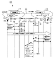
図1に、第1の実施形態のローミングネットワークシステムのシステム構成図およびシーケンスチャートを示す。同図に示すように、本実施形態のローミングネットワークシステム100は、VoIPネットワーク101上の各ゲートキーパー(以下「GK」という。)111,112,113に基地局(CS)131,132を対応させ、各基地局(CS)131,132が受け持つ無線通信エリア内の通信端末(PS)を各GK111,112,113に割り当てて構成されている。各基地局(CS)131,132は、それぞれゲートウェイ(以下「GW」という。)141,142を介してVoIPネットワーク101に接続されている。各GK111,112,113には、自GWに割り当てられた通信端末(PS)の端末情報(電話番号やIPアドレスなど)が登録されている。
【0018】
当該ローミングネットワークシステム100のシーケンスは以下の通りである。ここでは、特許請求の範囲の第1のゲートキーパーに該当するGK111をホーム装置(home)とし、第2のゲートキーパーに該当するGK112をローマー装置(roamer)とし、GK113をその他のGKとして説明する。また、図1中の符号151はホーム装置111に割り当てられた通信端末(PS1)であり、本実施形態ではPHS端末とする。したがって、当該通信端末を、以下、PHS端末151と表記する。なお、PHS端末(PS1)151はRCR STD−28に準拠したエンドポイントに相当する装置であり、GW141,142はH.323勧告に準拠したエンドポイントに相当する装置である。
【0019】
まず、PHS端末(PS1)151は、ホーム装置111が受け持つ無線通信エリア内に位置するときには、PHS基地局(CS)131およびGW141を介して、ホーム装置111に向けてRRQ(登録要求)信号を送る。ホーム装置111は、RRQ信号を受信し、自GKにて登録可能であれば登録処理を行うと共に、その旨を知らせるRCF(登録受付)信号をPHS端末(PS1)151に返送する。
【0020】
RCF信号を受け取ったPHS端末(PS1)151は、ホーム装置111を通じて他端末(PHS端末等のエンドポイント)と通信を行う。PHS端末(PS1)151は、ホーム装置111が受け持つ無線通信エリアから、ローマー装置112が受け持つ無線通信エリアへと移動すると、移動先のPHS基地局132およびGW142を介して、ローマー装置112に向けてRRQ信号を送る。
【0021】
ローマー装置112は、RRQ信号を受信し、自装置にて登録可能であれば登録処理を行ってPHS端末(PS1)151に対する呼制御を可能にすると共に、その旨を知らせるRCF信号をPHS端末(PS1)151に返送する。さらに、ローマー装置112は、ホーム装置111および他のGK113に、PHS端末(PS1)151がローマー装置112によって呼制御されていることを示すローミング通知メッセージを含んだLRQ信号をマルチキャスト送信する。当該LRQ信号は、ホーム装置111以外のGK113では無視される。
【0022】
ホーム装置111は、ローマー装置112から受信したLRQ信号に含まれるローミング通知メッセージに基づいて、自装置が管理しているPHS端末(PS1)151であると判断し、PHS端末(PS1)151のエンドポイント管理情報を含むLCF信号をローマー装置112に返送する。ホーム装置111は、ローマー装置112から受け取ったPHS端末(PS1)151のエンドポイント位置情報を自装置に登録し、PHS端末(PS1)151へのローミング制御を行う。
【0023】
次に、図2を参照して、ローマー装置112によって呼制御されている状態のPHS端末(PS1)151に対する発呼方法ついて説明する。図2中の符号161は発呼側IP電話であり、符号171は発呼側IP電話161を呼制御するGKである。
【0024】
発呼側IP電話161は、PHS端末(PS1)151を呼び出すためのARQ信号をGK171に送る。GK171は、ARQ信号を受信すると、ホーム装置111、ローマー装置112および他のGK113に、LRQ信号をマルチキャスト送信する。この場合、ホーム装置111は、PHS端末(PS1)151がローマー装置112の呼制御下にあることを把握しているので、LRQ信号に応答し、LCF信号を発呼側IP電話161のGK171に返す。当該LCF信号は、ホーム装置111の呼制御下でのPHS端末(PS1)151のエンドポイント位置情報(IPアドレス)を通知するものである。
【0025】
GK171は、LCF信号を受け取ると、PHS端末(PS1)151のIPアドレスを通知するACF信号を発呼側IP電話161に送信する。発呼側IP電話161は、通知されたIPアドレスへのコネクションを要求するセットアップ信号(Setup)をホーム装置111に送信する。ホーム装置111は、セットアップ信号を受け取ると、発呼側IP電話161とのコネクションを確立する。そして、発呼側IP電話161に、セットアップ信号に応じた受付信号(CallProc)を返した後、PHS端末(PS1)151のIPアドレズへのセットアップを要求するセットアップ信号(Setup)をローマー装置112に転送する。
【0026】
ローマー装置112は、セットアップ信号を受け取ると、ホーム装置111とのコネクションを確立する。そして、セットアップ信号に応じた受付信号(CallProc)をホーム装置111に返した後、セットアップ信号(Setup)をGW142に送信する。GW142は、セットアップ信号を受け取ると発呼側IP電話161とのコネクションを確立する。そして、ローマー装置112に、セットアップ信号に応じた受付信号(CallProc)を返した後、PHS基地局132を介してPHS端末(PS1)151を発呼する。この発呼に応答してPHS端末(PS1)151が着呼し、発呼側IP電話161とPHS端末(PS1)151との間でVoIPによる通話が可能となる。
【0027】
以上説明したように、本実施形態のローミングネットワークシステムによれば、複数のゲートキーパー間で相互にローミングサービスを提供することができる。また、QsigOverIP等の特別なソフトウェアを必要としないため、設計/開発する際の開発リソースを低減でき、かつ、専用のTCPコネクションを必要としないため、ゲートキーパーのTCPSocket等を余分に使用することがない。さらに、各ゲートキーパーに通信端末を事前に登録する必要がないため、システム拡張の際の煩雑な作業や処理を低減することができる。
【0028】
[第2の実施の形態]
次に、本発明の第2の実施形態について説明する。図3に、第2の実施形態のローミングネットワークシステムのシステム構成図およびシーケンスチャートを示す。このローミングネットワークシステム200は、システム構成に関しては図1と同じであるがシーケンスが異なる。
【0029】
本実施形態のローミングネットワークシステム200のシーケンスは以下の通りである。まず、PHS端末(PS1)151は、ホーム装置111が受け持つ無線通信エリアからローマー装置112が受け持つ無線通信エリアへと移動すると、移動先のPHS基地局132およびGW142を介して、ローマー装置112に向けてRRQ信号を送る。
【0030】
ローマー装置112は、RRQ信号を受信し、自装置にて登録可能であれば登録処理を行ってPHS端末(PS1)151に対する呼制御を可能にすると共に、その旨を知らせるRCF信号をPHS端末(PS1)151に返送する。さらに、ローマー装置112は、ホーム装置111および他のGK113に、PHS端末(PS1)151の位置解決のためのLRQ信号をマルチキャスト送信する。このLRQ信号は、ホーム装置111以外のGK113には無視される。
【0031】
ホーム装置111は、ローマー装置112から受信したLRQ信号に応答するLCF信号をローマー装置112に返信する。当該LCF信号は、ホーム装置111の呼制御下でのPHS端末(PS1)151のエンドポイント位置情報(IPアドレス)を通知するものである。ローマー装置112は、LCF信号を受信すると、ホーム装置111に対しコネクションを要求するセットアップ信号(Setup)を送信する。ホーム装置111は、セットアップ信号を受け取ると、ローマー装置112とのコネクションを確立する。そして、ローマー装置112にセットアップ信号に応じた受付信号(CallProc)を返信した後、両者間のコネクションが確立されたことを示すコネクト信号(connect)を送信する。
【0032】
ローマー装置112は、コネクト信号を受け取ると、PHS端末(PS1)151がローマー装置112によって呼制御されていることを示すローミング通知メッセージ(Facility)をホーム装置111に送信する。ホーム装置111は、ローミング通知メッセージにより通知された情報を自装置に登録した後、登録が完了したことを示す信号(RealComp)をローマー装置112に返信する。
【0033】
次に、図4を参照して、ローマー装置112によって呼制御されている状態のPHS端末(PS1)151に対する発呼方法ついて説明する。図2と同様に、図4中の符号161は発呼側IP電話であり、符号171は発呼側IP電話161を呼制御するGKである。
【0034】
発呼側IP電話161は、PHS端末(PS1)151を呼び出すためのARQ信号をGK171に送る。GK171は、ARQ信号を受信すると、ホーム装置111、ローマー装置112および他のGK113に、LRQ信号をマルチキャスト送信する。この場合、ホーム装置111は、PHS端末(PS1)151がローマー装置112の呼制御下にあることを把握しているので、LRQ信号に応答し、LCF信号を発呼側IP電話161のGK171に返す。当該LCF信号は、ホーム装置111の呼制御下でのPHS端末(PS1)151のエンドポイント位置情報(IPアドレス)を通知するものである。
【0035】
GK171は、LCF信号を受け取ると、PHS端末(PS1)151のIPアドレスを通知するACF信号を発呼側IP電話161に送信する。発呼側IP電話161は、通知されたIPアドレスへのコネクションを要求するセットアップ信号(Setup)をホーム装置111に送信する。ホーム装置111は、セットアップ信号を受け取ると、発呼側IP電話161とのコネクションを確立する。そして、発呼側IP電話161に、セットアップ信号に応じた受付信号(CallProc)を返した後、PHS端末(PS1)151のIPアドレズへのセットアップを要求するセットアップ信号(Setup)をローマー装置112に転送する。
【0036】
ローマー装置112は、セットアップ信号を受け取ると、ホーム装置111とのコネクションを確立する。そして、セットアップ信号に応じた受付信号(CallProc)をホーム装置111に返した後、セットアップ信号(Setup)をGW142に送信する。GW142は、セットアップ信号を受け取ると発呼側IP電話161とのコネクションを確立する。そして、ローマー装置112に、セットアップ信号に応じた受付信号(CallProc)を返した後、PHS基地局132を介してPHS端末(PS1)151を発呼する。この発呼に応答してPHS端末(PS1)151が着呼し、発呼側IP電話161とPHS端末(PS1)151との間でVoIPによる通話が可能となる。
【0037】
以上説明したように、本実施形態のローミングネットワークシステムによれば、複数のゲートキーパー間で相互にローミングサービスを提供することができる。また、第1の実施形態と異なり、ローマー装置112からマルチキャストで送られるLRQ信号にはローミング通知メッセージ(Facility)が含まれておらず、LRQ信号を送信したローマー装置に対してローミング通知メッセージ(Facility)を送るようにしているため、特別なプロトコルを用いることなくローミングサービスを提供することができる。
【0038】
【発明の効果】
以上説明したように、本発明に係るローミングネットワークシステムよれば、通信端末に対し、複数のゲートキーパー間で相互にローミングサービスを提供することができる。
【図面の簡単な説明】
【図1】第1の実施形態のローミングネットワークシステムのシステム構成図およびシーケンスチャートを示す図
【図2】第1の実施形態のローミングネットワークシステムにおける発呼の際のシーケンスチャート
【図3】第2の実施形態のローミングネットワークシステムのシステム構成図およびシーケンスチャート
【図4】第2の実施形態のローミングネットワークシステムにおける発呼の際のシーケンスチャート
【符号の説明】
100,200 ローミングネットワークシステム
101 VoIPネットワーク
111 ホーム装置
112 ローマー装置
113 他のゲートキーパー
131,132 PHS基地局
141,142 ゲートウェイ
151 PHS端末(PS1)
161 発呼側IP電話
171 発呼側IP電話のゲートキーパー[0001]
BACKGROUND OF THE INVENTION
The present invention relates to a roaming network system using a communication terminal such as a PHS, and more particularly to a roaming network system that enables a roaming service of a communication terminal.
[0002]
[Prior art]
ITU (International Telecommunication Union) established by ITU. In the H.323 recommendation, rules regarding address translation and access control by a gatekeeper (hereinafter referred to as “GK”) on a VoIP network are defined for an endpoint on the VoIP network.
[0003]
An endpoint on the VoIP network sends an RRQ (registration request) signal to the GK on the VoIP network in order to search for a GK that performs information registration of the own endpoint. The GK receives the RRQ signal, performs registration processing if registration is possible in the self-GK, and returns an RCF (registration acceptance) signal to that effect to the end point. The endpoint that has received the RCF signal communicates with other endpoints through the GK.
[0004]
A base station of a communication terminal such as a PHS corresponding to an end point is associated with each GK on such a VoIP network via a gateway (hereinafter referred to as “GW”), and the PHS protocol (RCR STD− By performing protocol conversion between 28) and VoIP, a roaming network system using PHS can be constructed in the VoIP network.
[0005]
[Problems to be solved by the invention]
However, in the conventional VoIP technology, there is no means for providing a roaming service between all PHS base stations connected to different GKs. As one of countermeasures for this, there is a method in which a dedicated TCP connection is fixed between all GKs that can roam with each other, and a roaming notification process using the Qsig (JT-Q931a) protocol is performed. .
[0006]
However, when this method is adopted, a special program for the Qsig protocol must be installed in all GKs, and all opposing GKs must be registered in each GK in advance. There was a problem that the cost increased and the expandability decreased.
[0007]
The present invention has been made in view of the above-described conventional problems, and it is an object of the present invention to provide a roaming network system that enables a roaming service between a plurality of networks without using a special technique.
[0008]
[Means for Solving the Problems]
In order to achieve the above object, a roaming network system according to the present invention manages assigned communication terminals, and assigns each assigned communication terminal to each other. Phone number and IP address When receiving an LRQ signal related to the communication terminal from another gatekeeper as a home device having IP address A first gatekeeper that returns an LCF signal including a message, and a communication terminal that uses the first gatekeeper as a home device moves to a region managed by the first gatekeeper and registers for the registration request from the communication terminal And registering a communication terminal having the first gatekeeper as a home device, the second gatekeeper being a roaming destination of the communication terminal that enables call control to the communication terminal by performing acceptance The second gatekeeper transmits the LRQ signal including the roaming notification message to the other gatekeepers including the first gatekeeper by multicast to transmit the communication from the first gatekeeper that is the home device of the communication terminal. Terminal IP address The roaming service between the gatekeepers is performed by receiving the LCF signal including the call, and the call control is performed by the second gatekeeper, and the communication terminal having the first gatekeeper as a home device makes a call from another terminal In response to the multicast transmission of the LRQ signal from another gatekeeper controlling the other terminal, the first gatekeeper, which is the home device of the communication terminal that is the call destination, IP address LCF signal including To the other gatekeeper Send back The other gatekeeper transmits the IP address of the communication terminal to the calling other terminal, and the calling other terminal sends a setup signal to the communication terminal of the received IP address to the first gatekeeper. And the first gatekeeper forwards the received setup signal to the second gatekeeper. Then, a connection is established between the first gatekeeper and the second gatekeeper to make a call between the communication terminal and another terminal.
[0009]
As described above, even when the communication terminal managed by the first gatekeeper moves to the area of the second gatekeeper, the second gatekeeper that receives the registration request from the communication terminal does not The LRQ signal including the roaming notification message is multicast-transmitted to other gatekeepers including the gatekeeper, and the first gatekeeper determines to perform roaming based on the roaming notification message of the LRQ signal. At this time, the first gatekeeper transmits an LCF signal to the second gatekeeper in response to the LRQ signal received from the second gatekeeper. Roaming service can be provided.
[0013]
In the roaming network system according to the present invention, the communication terminal transmits the roaming notification message. Roaming destination This message indicates that call control is being performed by the second gatekeeper.
[0015]
A roaming network system according to the present invention includes a mobile terminal, a radio base station that manages the mobile terminal, a gateway device that accommodates the radio base station, and a gatekeeper device that manages the gateway device. In the system, when the mobile terminal moves to a management area of another gatekeeper device, the mobile terminal transmits a registration request of its own device to the other gatekeeper device via a destination radio base station. The other gatekeeper device that has received the registration request performs registration processing of the mobile terminal, transmits registration acceptance to the mobile terminal, and manages call control of the mobile terminal with respect to other gatekeeper devices. Transmitting a signal including a roaming notification message indicating that the mobile terminal has received the signal and the home of the mobile terminal That Gatekeeper device of the mobile terminal when it is determined that the mobile terminal from a roaming notification message said received is a mobile terminal to a home self IP address Reply response signal including When the calling terminal makes a call to the mobile terminal after the mobile terminal has moved to the management area of another gatekeeper device, the calling side gatekeeper device that manages the calling terminal has a plurality of other gatekeepers. When the LRQ signal is transmitted to the device, and the home gatekeeper device that is the home of the mobile terminal among the gatekeeper devices that have received the LRQ signal returns a response signal including the IP address of the mobile terminal, the call The side gatekeeper device transmits a setup signal to the mobile terminal of the IP address to the home gatekeeper device, and the home gatekeeper device transfers the received setup signal to the other gatekeeper device of the movement destination. The home gatekeeper device and the other gatekeeper device to be moved Establishing a down causes a call between the calling terminal and the mobile terminal .
As described above, even when the mobile terminal moves to the management area of another gatekeeper device, the destination gatekeeper device that has received the registration request from the mobile terminal roams to another gatekeeper device including the home gatekeeper device. Since the signal including the notification message is multicast-transmitted, the home gatekeeper device can determine that roaming is performed based on the roaming notification message of the signal. At this time, the home gatekeeper device can provide the mobile terminal with a roaming service among the plurality of gatekeeper devices by returning a response signal to the destination gatekeeper device.
The roaming network system according to the present invention includes a mobile terminal, a radio base station that manages the mobile terminal, a gateway device that accommodates the radio base station, and a gatekeeper device that manages the gateway device. In the network system, when the mobile terminal moves to the management area of another gatekeeper device, the mobile terminal transmits a registration request of its own device to the other gatekeeper device via a destination radio base station. The other gatekeeper device that has received this registration request performs registration processing of the mobile terminal, transmits registration acceptance to the mobile terminal, and resolves the position of the mobile terminal to other gatekeeper devices. Any one of the gatekeeper devices that has received the signal for position resolution is transmitted to the mobile terminal. When a response signal including a P address is returned, a roaming notification message indicating that the other gatekeeper device establishes a connection with the gatekeeper device that has returned the response signal and manages call control of the mobile terminal The gatekeeper device that received the message registered the information in the message and returned a response message. When the calling terminal makes a call to the mobile terminal after the mobile terminal has moved to the management area of another gatekeeper device, the calling side gatekeeper device that manages the calling terminal has a plurality of other gatekeepers. When the LRQ signal is transmitted to the device, and the home gatekeeper device that is the home of the mobile terminal among the gatekeeper devices that have received the LRQ signal returns a response signal including the IP address of the mobile terminal, the call The side gatekeeper device transmits a setup signal to the mobile terminal of the IP address to the home gatekeeper device, and the home gatekeeper device transfers the received setup signal to the other gatekeeper device of the movement destination. The home gatekeeper device and the other gatekeeper device to be moved Establishing a down causes a call between the calling terminal and the mobile terminal .
In this way, since the response signal is received and the mobile terminal's home gatekeeper device is confirmed and then the roaming notification message is sent to the home gatekeeper device, the roaming service can be performed without using a special protocol. Can start.
In the roaming control method according to the present invention, when a mobile terminal moves to a management area of another gatekeeper device, the mobile terminal requests a registration request of the own device to the other gatekeeper device via a destination radio base station. The other gatekeeper device that has received the registration request performs registration processing of the mobile terminal and transmits a registration acceptance to the mobile terminal, and the mobile terminal of the mobile terminal with respect to other gatekeeper devices. A signal including a roaming notification message indicating that call control is managed is transmitted, and the gatekeeper device that is the home of the mobile terminal that has received this signal returns the mobile terminal from the received roaming notification message. If it is determined that the mobile terminal is IP address Reply response signal including When the calling terminal makes a call to the mobile terminal after the mobile terminal has moved to the management area of the other gatekeeper device, the calling side gatekeeper device that manages the calling terminal has a plurality of other gates. When an LRQ signal is transmitted to the keeper apparatus and the home gatekeeper apparatus that is the home of the mobile terminal among the gatekeeper apparatuses that have received the LRQ signal returns a response signal including the IP address of the mobile terminal, The call side gatekeeper device transmits a setup signal to the mobile terminal of the IP address to the home gatekeeper device, and the home gatekeeper device transfers the received setup signal to the other gatekeeper device of the destination. By connecting the home gatekeeper device and the other gatekeeper device to be moved to Establishing a Deployment causes a call between the calling terminal and the mobile terminal .
As described above, even when the mobile terminal moves to the management area of another gatekeeper device, the destination gatekeeper device that has received the registration request from the mobile terminal roams to another gatekeeper device including the home gatekeeper device. Since the signal including the notification message is multicast-transmitted, the home gatekeeper device can determine that roaming is performed based on the roaming notification message of the signal. At this time, the home gatekeeper device can provide the mobile terminal with a roaming service among the plurality of gatekeeper devices by returning a response signal to the destination gatekeeper device.
In addition, the roaming control method according to the present invention is configured such that when a mobile terminal moves to a management area of another gatekeeper device, the mobile terminal transmits its own device to the other gatekeeper device via a destination radio base station. The other gatekeeper device that has transmitted the registration request performs registration processing of the mobile terminal, transmits registration acceptance to the mobile terminal, and moves the mobile terminal to other gatekeeper devices. When one of the gatekeeper devices that transmits a signal for position resolution of the terminal and receives the signal for position resolution returns a response signal including the IP address of the mobile terminal, the other gatekeeper device A roaming notification message indicating that the mobile terminal manages call control by establishing a connection with the gatekeeper device that has returned the response signal. And it sends a message containing the message, transmits a response message gatekeeper device receiving the message to register the information in the message When the calling terminal makes a call to the mobile terminal after the mobile terminal has moved to the management area of the other gatekeeper device, the calling side gatekeeper device that manages the calling terminal has a plurality of other gates. When an LRQ signal is transmitted to the keeper apparatus and the home gatekeeper apparatus that is the home of the mobile terminal among the gatekeeper apparatuses that have received the LRQ signal returns a response signal including the IP address of the mobile terminal, The call side gatekeeper device transmits a setup signal to the mobile terminal of the IP address to the home gatekeeper device, and the home gatekeeper device transfers the received setup signal to the other gatekeeper device of the destination. By connecting the home gatekeeper device and the other gatekeeper device to be moved to Establishing a Deployment causes a call between the calling terminal and the mobile terminal .
In this way, since the response signal is received and the mobile terminal's home gatekeeper device is confirmed and then the roaming notification message is sent to the home gatekeeper device, the roaming service can be performed without using a special protocol. Can start.
[0016]
DETAILED DESCRIPTION OF THE INVENTION
Hereinafter, embodiments of a roaming network system according to the present invention will be described in detail in the order of [first embodiment] and [second embodiment] with reference to the drawings.
[0017]
[First Embodiment]
FIG. 1 shows a system configuration diagram and a sequence chart of the roaming network system according to the first embodiment. As shown in the figure, the
[0018]
The sequence of the
[0019]
First, when the PHS terminal (PS1) 151 is located in the wireless communication area that the
[0020]
The PHS terminal (PS1) 151 that has received the RCF signal communicates with another terminal (end point such as a PHS terminal) through the
[0021]
The
[0022]
Based on the roaming notification message included in the LRQ signal received from the
[0023]
Next, referring to FIG. 2, a method for calling the PHS terminal (PS1) 151 in a state where the call control is performed by the
[0024]
Calling
[0025]
When the
[0026]
When receiving the setup signal, the
[0027]
As described above, according to the roaming network system of the present embodiment, it is possible to provide a roaming service between a plurality of gatekeepers. In addition, since special software such as QsigOverIP is not required, development resources for design / development can be reduced, and a dedicated TCP connection is not required, so an extra gatekeeper TCPSocket may be used. Absent. Furthermore, since it is not necessary to register a communication terminal in advance in each gatekeeper, it is possible to reduce troublesome work and processing during system expansion.
[0028]
[Second Embodiment]
Next, a second embodiment of the present invention will be described. FIG. 3 shows a system configuration diagram and a sequence chart of the roaming network system according to the second embodiment. The
[0029]
The sequence of the
[0030]
The
[0031]
The
[0032]
When the
[0033]
Next, referring to FIG. 4, a calling method for the PHS terminal (PS1) 151 in a state where the call control is performed by the
[0034]
Calling
[0035]
When the
[0036]
When receiving the setup signal, the
[0037]
As described above, according to the roaming network system of the present embodiment, it is possible to provide a roaming service between a plurality of gatekeepers. Also, unlike the first embodiment, the roaming notification message (Facility) is not included in the LRQ signal sent by multicast from the
[0038]
【The invention's effect】
As described above, according to the roaming network system according to the present invention, a roaming service can be provided to a communication terminal between a plurality of gatekeepers.
[Brief description of the drawings]
FIG. 1 shows a system configuration diagram and a sequence chart of a roaming network system according to a first embodiment.
FIG. 2 is a sequence chart when a call is made in the roaming network system according to the first embodiment.
FIG. 3 is a system configuration diagram and sequence chart of a roaming network system according to a second embodiment.
FIG. 4 is a sequence chart when a call is made in the roaming network system according to the second embodiment.
[Explanation of symbols]
100,200 roaming network system
101 VoIP network
111 Home device
112 Roamer equipment
113 Other gatekeepers
131,132 PHS base station
141,142 gateway
151 PHS terminal (PS1)
161 Calling party IP phone
171 Calling IP phone gatekeeper
Claims (6)
前記第1のゲートキーパーをホーム装置とする通信端末が自己の管理する領域に移動してきたときに前記通信端末からの登録要求に対して登録受付を行うことにより、前記通信端末に対する呼制御を可能にする前記通信端末のローミング先となる第2のゲートキーパーと、を備え、
前記第1のゲートキーパーをホーム装置とする通信端末を登録した第2のゲートキーパーは、前記第1のゲートキーパーを含む他のゲートキーパーにローミング通知メッセージを含むLRQ信号をマルチキャストで送信して前記通信端末のホーム装置である前記第1のゲートキーパーから前記通信端末のIPアドレスを含むLCF信号を受信することによりゲートキーパー間のローミングサービスを行い、
前記第2のゲートキーパーによって呼制御され、前記第1のゲートキーパーをホーム装置とする通信端末に対して他端末から発呼されたとき、前記他端末を呼制御する他のゲートキーパーからのLRQ信号のマルチキャスト送信に対し、発呼先の通信端末のホーム装置である前記第1のゲートキーパーが前記通信端末のIPアドレスを含むLCF信号を前記他のゲートキーパーに返信すると、前記他のゲートキーパーは前記通信端末のIPアドレスを前記発呼した他端末に送信し、前記発呼した他端末は受信したIPアドレスの通信端末へのセットアップ信号を第1のゲートキーパーに送信し、第1のゲートキーパーは前記受信したセットアップ信号を第2のゲートキーパーに転送することにより、前記第1のゲートキーパーと前記第2のゲートキーパーとでコネクションを確立して前記通信端末と他端末との通話を行わせることを特徴とするローミングネットワークシステム。When the assigned communication terminal is managed and an LRQ signal related to the communication terminal is received from another gatekeeper as a home device having the telephone number and IP address of each assigned communication terminal, the IP address of the communication terminal is set. A first gatekeeper returning an LCF signal including:
When a communication terminal that uses the first gatekeeper as a home device moves to an area managed by the first gatekeeper, call control for the communication terminal can be performed by accepting a registration request from the communication terminal. A second gatekeeper serving as a roaming destination of the communication terminal,
A second gatekeeper that registers a communication terminal that uses the first gatekeeper as a home device transmits an LRQ signal including a roaming notification message to other gatekeepers including the first gatekeeper by multicast, and A roaming service between gatekeepers is performed by receiving an LCF signal including the IP address of the communication terminal from the first gatekeeper which is a home device of the communication terminal,
When a call is controlled by the second gatekeeper and a call is made from another terminal to a communication terminal using the first gatekeeper as a home device, the LRQ from another gatekeeper that controls the other terminal is called. In response to multicast transmission of a signal, when the first gatekeeper, which is the home device of the communication terminal of the call destination, returns an LCF signal including the IP address of the communication terminal to the other gatekeeper, the other gatekeeper The keeper transmits the IP address of the communication terminal to the other terminal that originated the call, and the other terminal that originated the call transmits a setup signal to the communication terminal of the received IP address to the first gatekeeper, by transferring the setup signal thus received to the second gatekeeper gatekeeper, the second gate and said first gatekeeper Roaming network system, characterized in that by establishing a connection to perform a call between the communication terminal and another terminal by the gatekeeper.
Priority Applications (1)
| Application Number | Priority Date | Filing Date | Title |
|---|---|---|---|
| JP2002150607A JP4014930B2 (en) | 2002-05-24 | 2002-05-24 | Roaming network system |
Applications Claiming Priority (1)
| Application Number | Priority Date | Filing Date | Title |
|---|---|---|---|
| JP2002150607A JP4014930B2 (en) | 2002-05-24 | 2002-05-24 | Roaming network system |
Publications (3)
| Publication Number | Publication Date |
|---|---|
| JP2003348232A JP2003348232A (en) | 2003-12-05 |
| JP2003348232A5 JP2003348232A5 (en) | 2005-02-17 |
| JP4014930B2 true JP4014930B2 (en) | 2007-11-28 |
Family
ID=29768427
Family Applications (1)
| Application Number | Title | Priority Date | Filing Date |
|---|---|---|---|
| JP2002150607A Expired - Fee Related JP4014930B2 (en) | 2002-05-24 | 2002-05-24 | Roaming network system |
Country Status (1)
| Country | Link |
|---|---|
| JP (1) | JP4014930B2 (en) |
Families Citing this family (3)
| Publication number | Priority date | Publication date | Assignee | Title |
|---|---|---|---|---|
| CN100388853C (en) * | 2004-07-27 | 2008-05-14 | 中兴通讯股份有限公司 | Method for logging on network temporarily for PHS users at foreign land |
| JP4568557B2 (en) | 2004-08-10 | 2010-10-27 | 株式会社エヌ・ティ・ティ・ドコモ | Mobile communication system and mobile station |
| CN100388865C (en) * | 2005-11-04 | 2008-05-14 | 中兴通讯股份有限公司 | Method for realizing cross-location positioning service in PHS system |
-
2002
- 2002-05-24 JP JP2002150607A patent/JP4014930B2/en not_active Expired - Fee Related
Also Published As
| Publication number | Publication date |
|---|---|
| JP2003348232A (en) | 2003-12-05 |
Similar Documents
| Publication | Publication Date | Title |
|---|---|---|
| US8014386B2 (en) | Method for providing VoIP services for wireless terminals | |
| KR100770931B1 (en) | Network interworking system and method for providing seamless voice service and short message service betweem wireless communication system | |
| AU2002225478B2 (en) | Method of providing packet voice call service in wireless communication network and network architecture therefor | |
| EP1678835B1 (en) | Dual-mode communication device and call handoff method | |
| CN100356815C (en) | Method and system for roaming between mobile network and wireless network | |
| CN100388712C (en) | Cellular to 802.11 voice roaming utilizing SIP signaling | |
| EP1762105B1 (en) | Routing calls to facilitate call handover | |
| EP1301056B1 (en) | A system for providing subscriber features within a telecommunications network | |
| US20050070288A1 (en) | Handover method and apparatus | |
| EP1762104A4 (en) | Inter-site call routing and roaming support | |
| JP2007142610A (en) | Mobile communication system, and call control server, method, and program | |
| JP5322325B2 (en) | Radio base station apparatus, handover control system, and handover control method | |
| JP4014930B2 (en) | Roaming network system | |
| CN106534126B (en) | Data communication method, device, cluster system and transfer platform | |
| JP2007251612A (en) | Ip telephone exchange, and method for roaming between ip telephone exchanges | |
| JP2007074260A (en) | Communication system and method of voice handovering | |
| US20030012162A1 (en) | Terminal agent representing wireless terminals in a voice over IP communication network | |
| KR100917927B1 (en) | Call forwarding method for processing mobile number portability for originating call of ip network and mobile communication system for the same | |
| JP3655224B2 (en) | Mobile communication system, call connection establishment method, gateway device, and communication terminal device | |
| JP2003348232A5 (en) | ||
| KR20030071400A (en) | Method for hand-off using session initiation protocol in all internet protocol network | |
| JP3954036B2 (en) | Modem communication method and modem communication system in PHS | |
| JP2011166369A (en) | Extension call method and communication system | |
| KR20060092475A (en) | Network interworking system and method for offering voice service in wireless network |
Legal Events
| Date | Code | Title | Description |
|---|---|---|---|
| A521 | Written amendment |
Free format text: JAPANESE INTERMEDIATE CODE: A523 Effective date: 20040309 |
|
| A621 | Written request for application examination |
Free format text: JAPANESE INTERMEDIATE CODE: A621 Effective date: 20040309 |
|
| A977 | Report on retrieval |
Free format text: JAPANESE INTERMEDIATE CODE: A971007 Effective date: 20060518 |
|
| A131 | Notification of reasons for refusal |
Free format text: JAPANESE INTERMEDIATE CODE: A131 Effective date: 20060530 |
|
| A521 | Written amendment |
Free format text: JAPANESE INTERMEDIATE CODE: A523 Effective date: 20060627 |
|
| A131 | Notification of reasons for refusal |
Free format text: JAPANESE INTERMEDIATE CODE: A131 Effective date: 20070206 |
|
| A521 | Written amendment |
Free format text: JAPANESE INTERMEDIATE CODE: A523 Effective date: 20070319 |
|
| TRDD | Decision of grant or rejection written | ||
| A01 | Written decision to grant a patent or to grant a registration (utility model) |
Free format text: JAPANESE INTERMEDIATE CODE: A01 Effective date: 20070815 |
|
| A61 | First payment of annual fees (during grant procedure) |
Free format text: JAPANESE INTERMEDIATE CODE: A61 Effective date: 20070912 |
|
| FPAY | Renewal fee payment (event date is renewal date of database) |
Free format text: PAYMENT UNTIL: 20100921 Year of fee payment: 3 |
|
| R150 | Certificate of patent or registration of utility model |
Free format text: JAPANESE INTERMEDIATE CODE: R150 |
|
| FPAY | Renewal fee payment (event date is renewal date of database) |
Free format text: PAYMENT UNTIL: 20110921 Year of fee payment: 4 |
|
| FPAY | Renewal fee payment (event date is renewal date of database) |
Free format text: PAYMENT UNTIL: 20120921 Year of fee payment: 5 |
|
| FPAY | Renewal fee payment (event date is renewal date of database) |
Free format text: PAYMENT UNTIL: 20130921 Year of fee payment: 6 |
|
| LAPS | Cancellation because of no payment of annual fees |