JP4013879B2 - Partition panel with shelves - Google Patents

Partition panel with shelves Download PDF

Info

Publication number
JP4013879B2
JP4013879B2 JP2003350689A JP2003350689A JP4013879B2 JP 4013879 B2 JP4013879 B2 JP 4013879B2 JP 2003350689 A JP2003350689 A JP 2003350689A JP 2003350689 A JP2003350689 A JP 2003350689A JP 4013879 B2 JP4013879 B2 JP 4013879B2
Authority
JP
Japan
Prior art keywords
frame
sides
attached
shelf
panel
Prior art date
Legal status (The legal status is an assumption and is not a legal conclusion. Google has not performed a legal analysis and makes no representation as to the accuracy of the status listed.)
Expired - Fee Related
Application number
JP2003350689A
Other languages
Japanese (ja)
Other versions
JP2005113562A (en
Inventor
雅規 石川
Current Assignee (The listed assignees may be inaccurate. Google has not performed a legal analysis and makes no representation or warranty as to the accuracy of the list.)
Itoki Corp
Original Assignee
Itoki Corp
Priority date (The priority date is an assumption and is not a legal conclusion. Google has not performed a legal analysis and makes no representation as to the accuracy of the date listed.)
Filing date
Publication date
Application filed by Itoki Corp filed Critical Itoki Corp
Priority to JP2003350689A priority Critical patent/JP4013879B2/en
Publication of JP2005113562A publication Critical patent/JP2005113562A/en
Application granted granted Critical
Publication of JP4013879B2 publication Critical patent/JP4013879B2/en
Anticipated expiration legal-status Critical
Expired - Fee Related legal-status Critical Current

Links

Images

Description

本発明は、棚付き間仕切パネルに係わり、更に詳しくは上下中間位置に棚板を備えた棚付き間仕切パネルに関するものである。   The present invention relates to a partition panel with shelves, and more particularly, to a partition panel with shelves provided with shelf plates at an upper and lower intermediate position.

従来、間仕切パネルにブラケットを介して棚板を取付けることは公知である。通常、間仕切パネルの両側縦枠若しくは連結用の支柱の表裏面側に上下方向に所定間隔毎に係止孔を形成し、そして間仕切パネル間の目地部に臨んだ前記係止孔にブラケットの基端部に設けたフックを嵌合係止し、該ブラケットに棚板を載置した状態で取付ける構造が一般的である。   Conventionally, attaching a shelf board to a partition panel via a bracket is known. Usually, locking holes are formed at predetermined intervals in the vertical direction on both sides of the vertical panels of the partition panels or on the front and back sides of the connecting columns, and the bracket holes are formed in the locking holes facing the joints between the partition panels. A structure in which a hook provided at an end is fitted and locked and a shelf plate is mounted on the bracket is generally installed.

例えば、特許文献1には、間仕切パネルのパネル板の前面側にブラケットを用いて任意の高さ位置に棚板を支持した構造が開示されている。また、特許文献2には、間仕切パネルの上部の表裏両面側にブラケットを取付け、左右二対のブラケットに棚板を載置して下方からネジ止めし、当該間仕切パネルの上端を跨ぐように取付けた棚板を、カウンターテーブルとして使用する構造が開示されている。   For example, Patent Document 1 discloses a structure in which a shelf plate is supported at an arbitrary height using a bracket on the front side of a panel plate of a partition panel. Also, in Patent Document 2, brackets are attached to the front and back both sides of the upper part of the partition panel, shelf boards are placed on the two left and right brackets, screwed from below, and attached so as to straddle the upper end of the partition panel. A structure in which the shelf board is used as a counter table is disclosed.

ところで、近年、室内空間のデザインの多様性を図り、また開放的な雰囲気を醸し出すために、間仕切パネルの一部に表裏に貫通する開口部を設けたオープン型パネルを使用することが増えているが、このオープン型パネルの開口部に棚板を設けることは従来は全くなく、またそのための構造の提案もなされてないのが現状である。
実公平6−1947号公報(第1図) 実開平5−46321号公報(図1、図3、図4)
By the way, in recent years, in order to diversify the design of indoor spaces and to create an open atmosphere, the use of open-type panels in which openings that penetrate the front and back are partly used in partition panels is increasing. However, there has never been a shelf in the opening of this open type panel, and no structure has been proposed for this purpose.
Japanese Utility Model Publication No. 6-1947 (Fig. 1) Japanese Utility Model Publication No. 5-46321 (FIGS. 1, 3, and 4)

そこで、本発明が前述の状況に鑑み、解決しようとするところは、間仕切パネルの一部に表裏に貫通する開口部を設けたオープン型パネルと棚板を組合わせた全く新しいタイプの棚付き間仕切パネルを提供する点にある。   Therefore, in view of the above-described situation, the present invention intends to solve a completely new type of partition with shelves that combines an open type panel and a shelf board provided with an opening penetrating the front and back of a part of the partition panel. The point is to provide a panel.

本発明は、前述の課題解決のために、間仕切パネルのフレームの両側縦杆又は両側支柱間の少なくとも一部に、表裏に貫通する開口部を形成し、該開口部内に配するとともに、両端部を前記縦杆又は支柱に取付けたブラケットで支持した棚板を設けてなる棚付き間仕切パネルであって、前記フレームの両側縦杆又は両側支柱の表裏両側に四角形状の額縁部材を取付けて前記開口部の周囲を形成し、前記額縁部材の縦枠の下部であって、表裏両側の額縁部材の突合せ部分の一部に切欠部を形成して、前記縦杆又は支柱の内側面を露出させ、前記ブラケットに該切欠部内に侵入する取付部を形成し、該取付部を前記縦杆又は支柱の内側面に取付けてなる棚付き間仕切パネルを構成した(請求項1)。 In order to solve the above-mentioned problem, the present invention forms an opening penetrating the front and back in at least a part between both sides of the frame of the partition panel or both columns, and arranges the both ends in the opening. A partition panel with shelves provided with shelves that are supported by brackets attached to the downspouts or support posts, wherein the openings are formed by attaching rectangular picture frame members on both front and back sides of the side downspouts or both side support posts of the frame. Forming a periphery of the part, forming a notch in a part of the butted portion of the frame member on both the front and back sides of the vertical frame of the frame member, and exposing the inner surface of the vertical fence or the column, A mounting portion that penetrates into the notch portion is formed in the bracket, and a partition panel with shelves is formed by mounting the mounting portion on the inner surface of the vertical gutter or the column (claim 1).

ここで、前記フレームの両側縦杆又は両側支柱の表裏両面に上下一対の開口を形成するとともに、四角形状の額縁部材の背面側両側上下部に設けた係止具を前記開口に嵌合係止して取付け、表裏両側に取付けた額縁部材にて前記開口部の周囲を形成してなることが好ましい(請求項2)。   Here, a pair of upper and lower openings are formed on both sides of the frame or both sides of the frame, and a locking tool provided on the upper and lower sides on the back side of the rectangular frame member is fitted and locked to the opening. It is preferable that the periphery of the opening is formed by a frame member attached on both the front and back sides (Claim 2).

また、前記棚板を間仕切パネルの表裏両側に突出するように前記開口部内の下端部に取付けてなることも好ましい(請求項3)。   Moreover, it is also preferable that the shelf board is attached to the lower end portion in the opening so as to protrude on both the front and back sides of the partition panel.

以上にしてなる請求項1に係る発明の棚付き間仕切パネルは、間仕切パネルの一部に表裏に貫通する開口部を設けたオープン型パネルと棚板を組合わせた全く新しいタイプの棚付き間仕切パネルを提供することができる。また、棚板を支持するブラケットを縦杆又は支柱の内側面に直接取付けることができるので、棚板の支持強度を高めることができる。 The partition panel with shelves of the invention according to claim 1 as described above is a completely new type of partition panel with shelves that combines an open type panel and a shelf board provided with an opening penetrating the front and back of a part of the partition panel. Can be provided. Moreover, since the bracket which supports a shelf board can be directly attached to a vertical shaft or the inner surface of a support | pillar, the support strength of a shelf board can be raised.

請求項2によれば、フレームの両側縦杆又は両側支柱の表裏両面に形成した上下一対の開口に、額縁部材の背面側両側上下部に設けた係止具を嵌合係止して取付けるだけで開口部を形成することができ、しかも前記一対の開口を縦杆又は支柱に上下方向に位置を変えて複数対形成しておくことにより、開口部を所望の高さに形成することができ、また複数の開口部を上下に並設することができ、更に開口部を設けない位置には開口を利用してパネル板を取付けて塞ぐこともできる。   According to the second aspect of the present invention, the fittings provided on the upper and lower portions on both sides of the back side of the frame member are fitted and locked to the pair of upper and lower openings formed on both sides of the frame or both sides of the frame. In addition, the openings can be formed at a desired height by forming a plurality of pairs of the above-mentioned pair of openings on a vertical shaft or a column while changing the position in the vertical direction. In addition, a plurality of openings can be arranged vertically, and a panel plate can be attached and closed using the openings at positions where no openings are provided.

請求項3によれば、間仕切パネルの表裏両側に棚板が突出するので、開口部と合わせて多様な使用形態を実現でき、例えば花瓶や装飾品を置いたり、カウンターとして使用することもでき、更に間仕切パネルで区画された室内空間のデザイン性を高めることができる。   According to claim 3, since the shelf boards protrude on both the front and back sides of the partition panel, various usage forms can be realized together with the opening, for example, a vase or a decoration can be placed or used as a counter, Furthermore, the design of the indoor space partitioned by the partition panel can be enhanced.

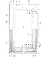
次に、本発明に係る棚付き間仕切パネルを、添付図面に基づき詳細に説明する。図1は棚付き間仕切パネルの構造を示し、図2〜図7はその詳細を示し、図中符号1はフレーム、2は額縁部材、3は棚板、4はブラケット、5はパネル板、6は巾木、7は笠木、8は側カバーをそれぞれ示している。また、図中符号Sは開口部を示している。   Next, the shelf-equipped partition panel according to the present invention will be described in detail with reference to the accompanying drawings. 1 shows the structure of a partition panel with shelves, and FIGS. 2 to 7 show the details thereof. In the figure, reference numeral 1 denotes a frame, 2 denotes a frame member, 3 denotes a shelf board, 4 denotes a bracket, 5 denotes a panel board, 6 Is a baseboard, 7 is a cap, and 8 is a side cover. In the figure, symbol S indicates an opening.

本発明に係る棚付き間仕切パネルは、前記フレーム1の表裏両面に、前記額縁部材2,2を取付けて開口部Sを形成するとともに、その他の部分には上下に複数に分割したパネル板5,…を着脱可能に取付け、そして前記棚板3を開口部S内に配するとともに、両端部を前記フレーム1の縦杆又は支柱に取付けたブラケット4,4で支持し、更に下端部に巾木6を取付け、上端には笠木7を取付け、更に端部に位置するフレーム1の側端には側カバー8を取付けた基本構造を有している。   The partition panel with shelves according to the present invention is provided with the frame members 2 and 2 on both front and back surfaces of the frame 1 to form an opening S, and the other portions are divided into a plurality of panel plates 5, Are attached in a detachable manner, and the shelf 3 is arranged in the opening S, and both ends are supported by brackets 4 and 4 attached to the vertical shaft or support of the frame 1, and further, the baseboard is attached to the lower end. 6 has a basic structure in which a cap 7 is attached to the upper end, and a side cover 8 is attached to the side end of the frame 1 located at the end.

前記フレーム1は、図2及び図6に示すように、角パイプからなる両側縦杆9,9の上下端部間に上横杆10と下横杆11をそれぞれ横設するとともに、上下中間部間に単又は複数の中横杆12を横設したものである。また、前記縦杆9の表面中央部には前記額縁部材2及びパネル板5を係止する上下一対の開口13,13を、上下方向に位置を変えて複数対形成するとともに、側端縁に沿った上下方向にオプション支持用のフックを係止するための係止孔14,…を一定間隔毎に形成している。   As shown in FIGS. 2 and 6, the frame 1 has an upper horizontal bar 10 and a lower horizontal bar 11 between upper and lower ends of both side vertical bars 9 and 9 made of square pipes, and an upper and lower middle part. A single or a plurality of medium horizontal ridges 12 are provided in between. Further, a plurality of pairs of upper and lower openings 13 and 13 for locking the frame member 2 and the panel plate 5 are formed at the center of the surface of the vertical rod 9 while changing the position in the vertical direction, and at the side edge. Lock holes 14,... For locking option support hooks are formed at regular intervals in the vertical direction along the line.

前記額縁部材2は、アルミニウムの押出し型材の端部を45度の角度で切断して両側縦枠15,15と上下横枠16,16を形成し、その切断部で突き合わせた状態でL金具17にてネジ止め連結し、正面視四角形状となしたものである。ここで、前記縦枠15は、断面略L字形を有し、前記フレーム1の縦杆9の前面側に位置する表面部15Aと縦杆9の約半分の厚さだけ内側面に沿って進入する内側面部15Bとを有している。また、前記横枠16も前記縦枠15と同じ断面形状を有している。そして、前記額縁部材2の両縦枠15,15の表面部15A,15Aの背面側上下部に前記一対の開口13,13に嵌合係止する係止具18,18をそれぞれ突設し、該係止具18,…を所定高さの縦杆9の開口13,…に嵌合係止して前記フレーム1の表裏両面から取付ける。そして、前記フレーム1の表裏両面に一対の額縁部材2,2を取付けると、各額縁部材2,2の内側面部15B,15Bが突き合わされ、該フレーム1の縦杆9を隠蔽し、両額縁部材2,2で前記開口部Sの周囲が形成される。   The frame member 2 is formed by cutting the end portion of the extruded aluminum material at an angle of 45 degrees to form both the vertical frames 15 and 15 and the upper and lower horizontal frames 16 and 16, and the L bracket 17 in a state of being abutted at the cut portions. Are screwed and connected to form a square shape when viewed from the front. Here, the vertical frame 15 has a substantially L-shaped cross section, and enters along the inner surface by a thickness of about half of the surface portion 15A located on the front surface side of the vertical rod 9 of the frame 1 and the vertical rod 9. And an inner side surface portion 15B. The horizontal frame 16 has the same cross-sectional shape as the vertical frame 15. And the locking tools 18 and 18 which are fitted and locked to the pair of openings 13 and 13 are respectively provided on the upper and lower portions on the back side of the surface portions 15A and 15A of the vertical frames 15 and 15 of the frame member 2, respectively. The fasteners 18 are fitted and locked to the openings 13 of the vertical rod 9 having a predetermined height and attached from both the front and back sides of the frame 1. When a pair of frame members 2 and 2 are attached to both the front and back surfaces of the frame 1, the inner side surface portions 15B and 15B of the frame members 2 and 2 are abutted to conceal the vertical rod 9 of the frame 1, and both frame members 2 and 2, the periphery of the opening S is formed.

前記パネル板5は、図4及び図7に示すように、スチール製の表面板19の背面側周囲に縁部20を形成し、少なくとも両側縁部20,20には前記表面板19と略平行な折曲板21を形成し、該折曲板21の上下部に取付孔(図示せず)を形成し、下方の取付孔に下部連結具22を内嵌するとともに、上方の取付孔に上部連結具23を内嵌したものである。そして、前記フレーム1の両側の縦杆9,9に形成した上下左右の開口13,…に、前記下部連結具22に設けた下向きフック24を係止するとともに、前記上部連結具23に設けた係合爪25を抜止め状態で弾性係合させて前記パネル板5を着脱自在に取付けるのである。尚、前記パネル板5は、前記表面板19を覆うようにクロスを張ったものでも良く、またクッション性を有する化粧シートを貼ったものでも、スチール面を塗装仕上げしたものでも良い。また、前記パネル板5として、多数の小孔が開いたパチングメタルや波板状に成形したものを採用することも可能である。   As shown in FIGS. 4 and 7, the panel plate 5 has an edge 20 around the back side of the steel surface plate 19, and at least both side edges 20, 20 are substantially parallel to the surface plate 19. A bent plate 21 is formed, mounting holes (not shown) are formed in the upper and lower portions of the bent plate 21, and a lower connector 22 is fitted in the lower mounting hole, and an upper portion is mounted in the upper mounting hole. The connector 23 is fitted inside. And the downward hook 24 provided in the said lower connector 22 was latched to the up-and-down left and right opening 13 formed in the vertical hooks 9 of both sides of the said frame 1, and it provided in the said upper connector 23 The panel plate 5 is detachably attached by elastically engaging the engaging claws 25 in the retaining state. Note that the panel plate 5 may be a cloth that covers the surface plate 19, a sheet having a cushioning decorative sheet attached thereto, or a steel surface that has been painted. Further, as the panel plate 5, it is also possible to employ a punching metal having a large number of small holes or a corrugated plate.

ここで、上下一対の開口13,13は最小単位であり、前記額縁部材2及びパネル板5の上下幅の最小単位に対応するが、連続する上下二対の最上位の開口13と最下位の開口13を用いれば最小単位の2倍の上下幅の額縁部材2及びパネル板5を取付けることができる。同様に、最小単位の整数倍の上下幅を有する前記額縁部材2及びパネル板5を上下方向に組合わせて取付けることができる。   Here, the pair of upper and lower openings 13 and 13 is a minimum unit and corresponds to the minimum unit of the vertical width of the frame member 2 and the panel plate 5, but two consecutive upper and lower uppermost openings 13 and the lowest unit. If the opening 13 is used, the frame member 2 and the panel plate 5 having a vertical width that is twice the minimum unit can be attached. Similarly, the frame member 2 and the panel plate 5 having a vertical width that is an integral multiple of the minimum unit can be attached in combination in the vertical direction.

本発明では、前記フレーム1に複数対の額縁部材2,2を上下方向に連続的に設けても良いが、本実施形態では適宜な高さ位置に一対の額縁部材2,2を取付けて開口部Sを形成し、他の空間は複数のパネル板5,…を取付けて覆っている。ここで、前記額縁部材2の上方横枠16の上縁には弾性材で作成した目地部材26を取付け、上方に位置するパネル板5の下縁との隙間を閉鎖するとともに、各パネル板5の上縁にも同様な目地部材26を取付けて、上方に位置するパネル板5の下縁との隙間及び前記笠木7との隙間を閉鎖している。本実施形態では、前記額縁部材2の上方横枠16の上縁とパネル板5の上縁の外形を一致させ、同じ目地部材26を装着できるようにしている。   In the present invention, a plurality of pairs of frame members 2 and 2 may be continuously provided in the frame 1 in the vertical direction. However, in the present embodiment, a pair of frame members 2 and 2 are attached at appropriate height positions and opened. A portion S is formed, and the other spaces are covered with a plurality of panel plates 5,. Here, a joint member 26 made of an elastic material is attached to the upper edge of the upper horizontal frame 16 of the frame member 2 to close the gap with the lower edge of the panel plate 5 located above, and each panel plate 5 A similar joint member 26 is also attached to the upper edge, and the gap with the lower edge of the panel plate 5 located above and the gap with the headboard 7 are closed. In the present embodiment, the upper edge of the upper horizontal frame 16 of the frame member 2 and the upper edge of the panel plate 5 are made to coincide with each other so that the same joint member 26 can be mounted.

そして、図1、図3及び図4に示すように、前記棚板3を間仕切パネルの表裏両側に突出するように前記開口部S内の下端部に取付けるのである。具体的には、図2〜図4に示すように、前記額縁部材2の縦枠15の下部であって、表裏両側の額縁部材2,2の突合せ部分の一部に、つまり前記縦枠15の内側面部15Bの下端縁部に切欠部27を形成して、前記縦杆9の内側面を露出させ、前記ブラケット4に該切欠部27内に侵入する取付部28を形成し、該取付部28を前記縦杆9の内側面にネジ止めして取付ける。前記ブラケット4は、金属板を加工して形成したものであり、側面視台形状の垂直な支持板29の中央部に断面コ字形に外側へ膨らんだ前記取付部28を形成するとともに、該取付部28を挟んだ両側の支持板29の下縁に前記棚板3を載置する受板30,30をそれぞれ直角に形成している。   Then, as shown in FIGS. 1, 3 and 4, the shelf board 3 is attached to the lower end portion in the opening S so as to protrude on both the front and back sides of the partition panel. Specifically, as shown in FIGS. 2 to 4, in the lower part of the vertical frame 15 of the frame member 2, a part of the butted portion of the frame members 2, 2 on both the front and back sides, that is, the vertical frame 15. A notch portion 27 is formed at the lower edge of the inner side surface portion 15B of the inner surface portion 15B to expose the inner surface of the vertical rod 9, and an attachment portion 28 that penetrates into the notch portion 27 is formed on the bracket 4. 28 is attached to the inner surface of the vertical rod 9 by screwing. The bracket 4 is formed by processing a metal plate. The bracket 4 is formed with the mounting portion 28 bulging outward in a U-shaped cross section at the center of a vertical support plate 29 having a trapezoidal shape in a side view. Receiving plates 30 and 30 for mounting the shelf plate 3 are formed at right angles on the lower edges of the support plates 29 on both sides of the portion 28.

前記ブラケット4の取付部28には、ネジ止め用の孔31を形成し、該取付部28を前記額縁部材2,2の切欠部27内に挿入した後、開口部S内からネジ32を孔31に通して直接縦杆9の内側面に螺合して取付けている。また、前記ブラケット4の各受板30には孔33を形成し、該受板30に載置した前記棚板3の端部に、前記孔33に下方から通したネジ34を螺合して当該棚板3を強固に取付けるのである。本実施形態では、前記棚板3は木製のものを用い、前記ネジ34を木ネジとしたが、前記棚板3はスチール製のものでも良く、その場合には棚板3の両端部下面に螺孔を形成しておき、前記ネジ34を小ネジとするか、又は棚板3に下穴を設けておき、タッピンネジを下穴に螺合するようにしても良い。尚、前記ブラケット4は、外側に突出した取付部28を設けずに、前記支持板29と同一平面の取付部(図示せず)とし、該取付部を前記額縁部材2の側枠16を介してフレーム1の縦杆9の内側面にネジ止めするなど適宜な固定手段で取付けることも可能であり、更に前記額縁部材2を用いないで開口部Sを形成する場合には、直接前記縦杆9の内側面に取付けることも可能である。   A screw fixing hole 31 is formed in the mounting portion 28 of the bracket 4. After the mounting portion 28 is inserted into the cutout portion 27 of the frame member 2, the screw 32 is inserted into the opening S. 31 is directly screwed onto the inner surface of the vertical rod 9 and attached. Further, each receiving plate 30 of the bracket 4 is formed with a hole 33, and a screw 34 passed through the hole 33 from below is screwed into an end portion of the shelf plate 3 placed on the receiving plate 30. The shelf board 3 is firmly attached. In this embodiment, the shelf board 3 is made of wood and the screws 34 are made of wood screws. However, the shelf board 3 may be made of steel. A screw hole may be formed, and the screw 34 may be a small screw, or a prepared hole may be provided in the shelf plate 3, and the tapping screw may be screwed into the prepared hole. The bracket 4 is not provided with a mounting portion 28 protruding outward, but is a mounting portion (not shown) in the same plane as the support plate 29, and the mounting portion is interposed via the side frame 16 of the frame member 2. It is also possible to attach it with an appropriate fixing means such as screwing to the inner surface of the vertical shaft 9 of the frame 1, and when the opening S is formed without using the frame member 2, the vertical shaft is directly It is also possible to attach to the inner surface of 9.

本実施形態では、図示しないが、複数の間仕切パネルを直線状に連結するには、前記フレーム1の縦杆9を隣接するフレーム1の縦杆9に接合し、両縦杆9,9を貫通したボルト、ナットで締付けて連結する構造となっている。このように、複数の間仕切パネルを連設する場合には、先ずフレーム1,1同士を連結した後、各フレーム1に前記額縁部材2あるいはパネル板5を所定位置に取付けるようにする。   In this embodiment, although not shown, in order to connect a plurality of partition panels in a straight line, the vertical rod 9 of the frame 1 is joined to the vertical rod 9 of the adjacent frame 1 and penetrates both vertical rods 9 and 9. It is structured to be connected by tightening with bolts and nuts. Thus, when connecting a plurality of partition panels, first, the frames 1 and 1 are connected to each other, and then the frame member 2 or the panel plate 5 is attached to each frame 1 at a predetermined position.

また、本実施形態では、前記額縁部材2をフレーム1に取付ける構造として、縦杆9に設けた開口13,13に、前記額縁部材2の両側上下部に取付けた係止具18,18を嵌合係止する構造を採用したが、前記額縁部材2の縦枠15の内側面部15Bに形成した切欠部27にブラケット4の取付部28が嵌合した状態で、該取付部28を縦杆9の内側面にネジ止めして取付けたので、各額縁部材2は上方へ移動することがなく、従って前記係止具18,18が開口13,13から外れることがないのである。尚、本実施形態では、前記開口部Sの下端部に棚板3を設けたので、つまり棚板3は額縁部材2の下方の横枠16に接近した位置、あるいは載置された状態にあるので、この棚板3によっても前記額縁部材2の上方移動は規制されるのである。一方、前記棚板3の中央部が両額縁部材2,2の下方横枠16,16に載置されるので、棚板3の中央部の下方への撓みを防止することができるのである。   In the present embodiment, the frame member 2 is attached to the frame 1, and the fasteners 18, 18 attached to the upper and lower parts on both sides of the frame member 2 are fitted into the openings 13, 13 provided in the vertical rod 9. Although a structure for engaging and locking is adopted, the attachment portion 28 is connected to the vertical rod 9 in a state where the attachment portion 28 of the bracket 4 is fitted to the notch portion 27 formed in the inner side surface portion 15B of the vertical frame 15 of the frame member 2. Since each frame member 2 does not move upward, the locking members 18 and 18 are not detached from the openings 13 and 13. In the present embodiment, since the shelf plate 3 is provided at the lower end of the opening S, that is, the shelf plate 3 is in a position close to or placed on the horizontal frame 16 below the frame member 2. Therefore, the upward movement of the frame member 2 is also restricted by the shelf plate 3. On the other hand, since the central part of the shelf 3 is placed on the lower horizontal frames 16 and 16 of the frame members 2 and 2, the downward deflection of the central part of the shelf 3 can be prevented.

また、前記開口部S内に棚板3を取付ける他の構造として図8には、前記フレーム1の縦杆9,9に形成した係止孔14,…に棚受ブラケット35のフックを嵌合係止し、該棚受ブラケット35,…に開口部S内に配した棚板3を載置固定する構造を示している。つまり、前記棚板3は、横方向の長さを前記額縁部材2あるいはパネル板5の横幅と同じか若干長く設定し、その両側端中央部には前記額縁部材2,2の縦枠15,15を収容する凹部36,36を形成したものを用いる。そして、前記開口部S内の下部に当該棚板3を装着するとともに、当該間仕切パネルの額縁部材2又はパネル板5と、隣接する間仕切パネル間又は側カバー8間の縦目地部に臨んだ前記係止孔14,…に、前記棚受ブラケット35の基端部に形成したフック37,37を嵌合係止し、当該間仕切パネルの左右両側部の表裏両面側に設けた棚受ブラケット35,…に前記棚板3の両端部を載置し、下方からネジ止めするなどの固定手段で取付けるのである。   Further, as another structure for attaching the shelf board 3 in the opening S, FIG. 8 shows that the hooks of the shelf support brackets 35 are fitted into the locking holes 14 formed in the vertical rods 9 of the frame 1. The structure which latches and mounts and fixes the shelf board 3 arrange | positioned in the opening part S to this shelf receiving bracket 35, ... is shown. That is, the shelf plate 3 is set to have a horizontal length equal to or slightly longer than the horizontal width of the frame member 2 or the panel plate 5, and the vertical frames 15, 15 having recesses 36 and 36 for housing 15 are used. And while attaching the said shelf board 3 to the lower part in the said opening part S, it faced the vertical joint part between the frame member 2 or the panel board 5 of the said partition panel, and between adjacent partition panels, or between the side covers 8. The hooks 37, 37 formed on the base end portion of the shelf receiving bracket 35 are fitted and locked in the locking holes 14, ..., and the shelf receiving brackets 35 provided on the front and back both sides of the left and right side portions of the partition panel, The both ends of the shelf plate 3 are mounted on the plate and attached by fixing means such as screwing from below.

また、本実施形態では、前記開口部S内に棚板3を1枚設けたが、棚板3を2枚以上多段に設けることも勿論可能である。更に、前記開口部Sを上下に複数形成した場合には、複数の開口部Sに棚板3を設けることも可能である。また、前記棚板3以外の開口部Sには、両額縁部材2,2間に透明なガラス板や合成樹脂板を挟み込んで設けることも可能である。   In this embodiment, one shelf board 3 is provided in the opening S, but it is of course possible to provide two or more shelf boards 3 in multiple stages. Further, when a plurality of the openings S are formed in the vertical direction, the shelf plate 3 can be provided in the plurality of openings S. In addition, a transparent glass plate or synthetic resin plate may be sandwiched between the frame members 2 and 2 in the opening S other than the shelf plate 3.

本実施形態では、間仕切パネルの構造として、両側縦杆9,9と上下横杆10,11で構成したフレーム1の表裏両面に、額縁部材2やパネル板5を取付ける構造のものを示したが、上下の天レールと地レール間に間隔をおいて複数の支柱を立設し、隣接する支柱間に前記額縁部材2やパネル板5を取付ける構造でも良い。   In the present embodiment, as the structure of the partition panel, a structure in which the frame member 2 and the panel plate 5 are attached to both front and back surfaces of the frame 1 constituted by the double vertical bars 9 and 9 and the upper and lower horizontal bars 10 and 11 is shown. A structure may be employed in which a plurality of columns are erected with an interval between the upper and lower ceiling rails and the ground rail, and the frame member 2 and the panel plate 5 are attached between adjacent columns.

本発明に係る棚付き間仕切パネルの全体斜視図である。It is a whole perspective view of the partition panel with a shelf which concerns on this invention. 同じく要部の一部を破断して示した分解斜視図である。It is the disassembled perspective view which fractured | ruptured and showed the principal part similarly. 同じく要部の一部を破断して示した斜視図である。It is the perspective view which fractured | ruptured and showed the principal part similarly. 同じく要部の縦断面図である。It is the longitudinal cross-sectional view of the principal part similarly. 同じく要部の一部破断して示した正面図である。It is the front view which fractured | ruptured and showed the principal part similarly. フレームの正面図である。It is a front view of a frame. フレームにパネル板を取付けた状態の部分側面図である。It is a partial side view of the state which attached the panel board to the flame | frame. 開口部内に配した棚板の他の支持構造を示す斜視図である。It is a perspective view which shows the other support structure of the shelf provided in the opening part.

符号の説明Explanation of symbols

S 開口部 1 フレーム
2 額縁部材 3 棚板
4 ブラケット 5 パネル板
6 巾木 7 笠木
8 側カバー 9 縦杆
10 上横杆 11 下横杆
12 中横杆 13 開口
14 係止孔 15 縦枠
15A 表面部 15B 内側面部
16 横枠 17 L金具
18 係止具 19 表面板
20 縁部 20 折曲板
22 下部連結具 23 上部連結具
24 下向きフック 25 係合爪
26 目地部材 27 切欠部
28 取付部 29 支持板
30 受板 31 孔
32 ネジ 33 孔
34 ネジ 35 棚受ブラケット
36 凹部 37 フック
DESCRIPTION OF SYMBOLS S Opening part 1 Frame 2 Frame member 3 Shelf board 4 Bracket 5 Panel board 6 Skirting board 7 Coping board 8 Side cover 9 Vertical gutter 10 Upper horizontal gutter 11 Lower horizontal gutter 12 Middle horizontal gutter 13 Opening 14 Locking hole 15 Vertical frame 15A Surface Part 15B Inner side surface part 16 Horizontal frame 17 L metal fitting 18 Locking tool 19 Surface plate 20 Edge part 20 Bending plate 22 Lower connection tool 23 Upper connection tool 24 Downward hook 25 Engagement claw 26 Joint member 27 Notch part 28 Attachment part 29 Support Plate 30 Receiving plate 31 Hole 32 Screw 33 Hole 34 Screw 35 Shelf receiving bracket 36 Recessed portion 37 Hook

Claims (3)

間仕切パネルのフレームの両側縦杆又は両側支柱間の少なくとも一部に、表裏に貫通する開口部を形成し、該開口部内に配するとともに、両端部を前記縦杆又は支柱に取付けたブラケットで支持した棚板を設けてなる棚付き間仕切パネルであって、前記フレームの両側縦杆又は両側支柱の表裏両側に四角形状の額縁部材を取付けて前記開口部の周囲を形成し、前記額縁部材の縦枠の下部であって、表裏両側の額縁部材の突合せ部分の一部に切欠部を形成して、前記縦杆又は支柱の内側面を露出させ、前記ブラケットに該切欠部内に侵入する取付部を形成し、該取付部を前記縦杆又は支柱の内側面に取付けてなることを特徴とする棚付き間仕切パネル。 An opening that penetrates the front and back sides is formed in at least a part of both sides of the frame of the partition panel or on both sides of the support panel, and both ends are supported by brackets attached to the vertical fence or support. A shelf- equipped partition panel provided with a shelf plate , wherein a rectangular frame member is attached to both sides of the frame or both sides of the column to form the periphery of the opening, and the frame member A lower portion of the frame, where a notch portion is formed in a part of the abutting portion of the frame member on both sides of the front and back sides, an inner surface of the downboard or the column is exposed, and an attachment portion that enters the bracket into the notch portion A partition panel with shelves, characterized in that the partitioning panel is formed and attached to the inner surface of the downspout or the column . 前記フレームの両側縦杆又は両側支柱の表裏両面に上下一対の開口を形成するとともに、四角形状の額縁部材の背面側両側上下部に設けた係止具を前記開口に嵌合係止して取付け、表裏両側に取付けた額縁部材にて前記開口部の周囲を形成してなる請求項1記載の棚付き間仕切パネル。   A pair of upper and lower openings are formed on both sides of the frame or both sides of the frame, and a locking tool provided on the upper and lower sides on the back side of the rectangular frame member is fitted and locked to the opening. The partition panel with shelves according to claim 1, wherein the periphery of the opening is formed by frame members attached to both the front and back sides. 前記棚板を間仕切パネルの表裏両側に突出するように前記開口部内の下端部に取付けてなる請求項1又は2記載の棚付き間仕切パネル。   The partition panel with a shelf according to claim 1 or 2, wherein the shelf plate is attached to a lower end portion in the opening so as to protrude on both front and back sides of the partition panel.
JP2003350689A 2003-10-09 2003-10-09 Partition panel with shelves Expired - Fee Related JP4013879B2 (en)

Priority Applications (1)

Application Number Priority Date Filing Date Title
JP2003350689A JP4013879B2 (en) 2003-10-09 2003-10-09 Partition panel with shelves

Applications Claiming Priority (1)

Application Number Priority Date Filing Date Title
JP2003350689A JP4013879B2 (en) 2003-10-09 2003-10-09 Partition panel with shelves

Publications (2)

Publication Number Publication Date
JP2005113562A JP2005113562A (en) 2005-04-28
JP4013879B2 true JP4013879B2 (en) 2007-11-28

Family

ID=34542171

Family Applications (1)

Application Number Title Priority Date Filing Date
JP2003350689A Expired - Fee Related JP4013879B2 (en) 2003-10-09 2003-10-09 Partition panel with shelves

Country Status (1)

Country Link
JP (1) JP4013879B2 (en)

Families Citing this family (6)

* Cited by examiner, † Cited by third party
Publication number Priority date Publication date Assignee Title
JP2007002488A (en) * 2005-06-23 2007-01-11 Itoki Corp Opening device in panel system for partitioning large room into private room
JP2007016568A (en) * 2005-07-11 2007-01-25 Itoki Corp Opening device of partition panel
JP2007020656A (en) * 2005-07-12 2007-02-01 Okamura Corp Appliance for supporting medical-related work
KR100874106B1 (en) 2008-08-07 2008-12-15 정의봉 Kitchen structure for movable heating cooking device
JP5261547B2 (en) * 2011-07-29 2013-08-14 三洋スーパースタンド株式会社 Product display shelf
KR102482909B1 (en) * 2021-12-17 2022-12-28 김홍엽 Partition with built-in prefabricated shelf function in the middle part

Also Published As

Publication number Publication date
JP2005113562A (en) 2005-04-28

Similar Documents

Publication Publication Date Title
US5682719A (en) Screen combination
US20160017605A1 (en) Wall panel connecting system for modular building units
JP4013879B2 (en) Partition panel with shelves
JP4914161B2 (en) Vertical beam mounting structure
JP4635647B2 (en) Furniture leg equipment
JP2004180952A (en) Mounting structure of panel, and knockdown counter unit with it
JP4811113B2 (en) Transparent panel device
JP4981582B2 (en) Partition panel
JP2699806B2 (en) Wall panels and walls
JP2021161739A (en) Jig for wall connection and outer wall panel member provided with the jig
JP4943934B2 (en) Blindfold panel fixing structure
JP4182482B2 (en) Raw partition
JPS642015Y2 (en)
JP4108079B2 (en) Shelf support structure of assembly house
JP4013882B2 (en) Partition panel bending prevention device
JP3974812B2 (en) Mounting structure of window frame sash to beam
JPH0733636Y2 (en) Water receiving device for gardening assembly shelf
JP3645025B2 (en) External wall panel mounting structure
KR200439457Y1 (en) Sectional partition
JP4044465B2 (en) outer wall
JPH0433291Y2 (en)
JP2006214121A (en) Fence
JP2517911Y2 (en) Assembly shelves for gardening, etc.
JP2891148B2 (en) Wall panels and structures
JPH026856Y2 (en)

Legal Events

Date Code Title Description
A621 Written request for application examination

Free format text: JAPANESE INTERMEDIATE CODE: A621

Effective date: 20050530

A977 Report on retrieval

Free format text: JAPANESE INTERMEDIATE CODE: A971007

Effective date: 20070301

A131 Notification of reasons for refusal

Free format text: JAPANESE INTERMEDIATE CODE: A131

Effective date: 20070424

A521 Written amendment

Free format text: JAPANESE INTERMEDIATE CODE: A523

Effective date: 20070618

TRDD Decision of grant or rejection written
A01 Written decision to grant a patent or to grant a registration (utility model)

Free format text: JAPANESE INTERMEDIATE CODE: A01

Effective date: 20070821

A61 First payment of annual fees (during grant procedure)

Free format text: JAPANESE INTERMEDIATE CODE: A61

Effective date: 20070903

FPAY Renewal fee payment (event date is renewal date of database)

Free format text: PAYMENT UNTIL: 20100921

Year of fee payment: 3

R150 Certificate of patent or registration of utility model

Free format text: JAPANESE INTERMEDIATE CODE: R150

FPAY Renewal fee payment (event date is renewal date of database)

Free format text: PAYMENT UNTIL: 20110921

Year of fee payment: 4

FPAY Renewal fee payment (event date is renewal date of database)

Free format text: PAYMENT UNTIL: 20120921

Year of fee payment: 5

FPAY Renewal fee payment (event date is renewal date of database)

Free format text: PAYMENT UNTIL: 20130921

Year of fee payment: 6

LAPS Cancellation because of no payment of annual fees