JP4013137B2 - Image reading device - Google Patents
Image reading device Download PDFInfo
- Publication number
- JP4013137B2 JP4013137B2 JP2002357632A JP2002357632A JP4013137B2 JP 4013137 B2 JP4013137 B2 JP 4013137B2 JP 2002357632 A JP2002357632 A JP 2002357632A JP 2002357632 A JP2002357632 A JP 2002357632A JP 4013137 B2 JP4013137 B2 JP 4013137B2
- Authority
- JP
- Japan
- Prior art keywords
- shielding member
- light
- light shielding
- substrate
- imaging lens
- Prior art date
- Legal status (The legal status is an assumption and is not a legal conclusion. Google has not performed a legal analysis and makes no representation as to the accuracy of the status listed.)
- Expired - Fee Related
Links
Images


Description
【0001】
【発明の属する技術分野】
本発明は、原稿からの反射光をイメージセンサに結像して画像読取りを行う画像読取装置に関し、特に、結像レンズの周辺光量の低下に対してイメージセンサに入射する光量を均一にすることが可能な画像読取装置に関する。
【0002】
【従来の技術】
スキャナ、ファクシミリ、複写機等では、一般に、プラテンガラス上に載置された紙等の原稿に対し、該プラテンガラスの下方において光源及び反射ミラー等を走査して、又はオート・ドキュメント・フィーダ(ADF)により原稿を自動搬送しながら原稿に光を照射して、原稿からの反射光をCCD等のイメージセンサに結像して画像読取りを行っている。
【0003】
前記光源には配光特性のバラツキがあり、例えば主走査位置(読取ライン方向)に棒状の光源である場合、その軸方向すべてにおいて光量は均等ではなく、一般に、中央部で多く端部付近では少ない。このような光量の偏りはイメージセンサに結像される画像の出力分布の偏りとなり、画像読取精度を劣化させる原因の一つとなる。また、結像レンズ周辺部の光量不足による出力信号レベルの低下は、従来、シェーディング補正回路により電気的に増幅させていた。
【0004】
前述したような光源の配光特性のバラツキを調整するものとして、光源の軸方向に渡って複数の光量調整板を設け、光源から原稿へ入射する光を各光量調整板で部分的に遮光する照明装置が考案されている(特許文献1参照)。該装置によれば、各光量調整板を光源の中央に対して大きく突出させ、両端では小さく突出させて、光源から原稿へ入射する光量が均等となるように調整することができる。また、光源の光を原稿方向へ反射するリフレクタの反射面の中央部に黒の印刷層を部分的に形成して反射率を低減させることにより、又は切欠を設けて光源の光をリフレクタの背面へ逃がすことにより、光源から原稿へ入射する光量を均等にする原稿照明装置も考案されている(特許文献2参照)。
【0005】
【特許文献1】
特開平7−319081号公報
【特許文献2】
特開平8−204906号公報
【0006】
【発明が解決しようとする課題】
スキャナ、ファクシミリ、複写機等における画像読取りでは、反射ミラー等によりイメージセンサへ導かれた原稿からの反射光は、結像レンズによりイメージセンサの読取面上に収束されるところ、前述したような従来の照明装置により原稿へ入射される光量を均等なものとしても、結像レンズにおける所謂cos4乗則による周辺部の光量不足や、イメージセンサの感度の個体間のバラツキ等によっても、原稿の主走査位置(読取ライン)において出力信号のレベルにバラツキが生じる。
【0007】
また、結合レンズの周辺部の光量不足によるイメージセンサへの入射光量のバラツキを補正するために、イメージセンサの出力をシェーディング補正回路により電気的に増幅させることとすれば、イメージセンサの出力信号中のノイズも増幅されるので、増幅された部分のダイナミックレンジは低下する。特に、カラー画像の読取りにおけるRGB夫々について、例えば8ビット、256階調で読取りを行う場合に、前述したような電気的な増幅によるシェーディング補正を行えば、光量不足部分のダイナミックレンジが低下した結果、同一原稿の同一色について、原稿の中央部と両端部で色ズレが生じるという問題がある。
【0008】
本発明は、これらの点に鑑みてなされたものであり、光源の配光特性や結像レンズの周辺光量不足等によりイメージセンサへ入射される光量のバラツキを、色ズレ等を生じさせることなく、容易且つ簡便に補正することが可能な画像読取装置を提供することを目的とする。
【0009】
【課題を解決するための手段】
本発明に係る画像読取装置は、原稿からの反射光を結像レンズを透過させてイメージセンサに結像することにより画像読取りを行い、前記結像レンズに入射する光を前記イメージセンサの読取ラインに対応して制限する絞り機構を具備する画像読取装置において、前記絞り機構が、原稿からの反射光を通すための開口部が形成されて前記結像レンズの前方に設けられる基板と、前記開口部の一部分を遮蔽するようにして前記基板に取り付けられる遮光部材とを備え、前記基板に、前記遮光部材の取付位置を調整するための複数の位置決め孔が、所定間隔で列設され、且つ、段違い状に複数列形成される一方、前記遮光部材に、前記基板のいずれかの列の位置決め孔に嵌入可能な複数の爪が、それぞれ突設されたものである。
【0010】
また、本発明に係る画像読取装置は、前記遮光部材が、前記開口部の上側の一部分を遮蔽する位置調整可能な上遮光部材と、下側の一部分を遮蔽する位置調整可能な下遮光部材とを備えるものである。
【0011】
【発明の実施の形態】
以下、本発明の実施の形態に係る画像読取装置を図面に基づき具体的に説明する。なお、本実施の形態に係る画像読取装置は本発明の一例にすぎず、本発明の構成が該画像読取装置に限定されるものでないことは当然である。
【0012】
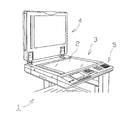
図1は、本発明の実施の形態に係る画像読取装置100を具備するコピー・ファクシミリ複合機1の上部の外観を示す概略斜視図である。図に示すように、該コピー・ファクシミリ複合機1は、読み取るべき原稿を載置するプラテンガラス2が配設された読取載置台3と、該原稿をプラテンガラス2上に押圧して固定する原稿押さえカバー4と、原稿の読取り開始等を入力するための操作パネル5とを具備してなる。以下に詳述する画像読取装置100は、読取載置台3の筐体内に配設されており、プラテンガラス2の下方から原稿の画像を読み取るようになっている。
【0013】
なお、図には示していないが、前記コピー・ファクシミリ複合機1は、読み取った画像を記録するための記録用紙を供給する給紙部や、記録用紙に画像を記録する画像記録部、画像を電送するための送信部等をも備えているが、該コピー・ファクシミリ複合機1は、本発明に係る画像読取装置を具備する機器の一例であり、これら画像記録部等は任意の構成であることは勿論である。
【0014】
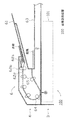
図2は、前記読取載置台3及び原稿押さえカバー4の縦断面を示す図であるが、図に示すように、本画像読取装置100は、プラテンガラス2上に載置された原稿を読み取るフラットベッドスキャナ(FBS)として構成され、且つ原稿押えカバー4のADF6により自動搬送される原稿も読み取るように構成されている。該ADF6は、読み取るべき原稿の束が載置される給紙トレイ61と、該原稿の束から最上紙を取り出して供給するピックアップローラ62a、セパレートローラ62b、及びリタードローラ62cと、供給された原稿を下方へ反転させながら排紙トレイ63へ案内する搬送路64と、搬送路64に適宜配置されて原稿を搬送する搬送ローラ65と、搬送路64の最下流に配設された排紙トレイ63とを具備してなる。このように構成されたADF6により、給紙トレイ61から搬送路64へ順次繰り込まれた原稿は、プラテンガラス2の読取位置Pを通過し、該読取位置Pにおいて画像読取りがされた後、排紙トレイ63へ排出されるようになっている。
【0015】
プラテンガラス2の下方には、FBS使用時にはプラテンガラス2の下方を水平方向へ移動しながらプラテンガラス2上の原稿をスキャンし、前記ADF6使用時には読取位置Pへ移動して順次搬送される原稿をスキャンする画像読取ユニット101が設けられている。
【0016】
図3は、前記画像読取ユニット101の主要構成を示した図であるが、図に示すように、前記プラテンガラス2の下方には、プラテンガラス2と平行方向に走査されるフルレートキャリッジ102及びハーフレートキャリッジ103が設けられている。該フルレートキャリッジ102は、キャリッジ本体20に、原稿に光を照射するための光源21と、原稿からの反射光R1を走査方向へ反射してハーフレートキャリッジ103へ導くための反射ミラー22とを具備してなり、前記ハーフレートキャリッジ103は、キャリッジ本体30に、フルレートキャリッジ102からの反射光R2をスキャナユニット105へ導く2枚の反射ミラー31,32を具備してなるものである。このように構成されたフルレートキャリッジ102及びハーフレートキャリッジ103が、図示しないガイドレールにより夫々摺動可能に担持されている。
【0017】
さらに、前記フルレートキャリッジ102及びハーフレートキャリッジ103の両端部に沿って一対のベルト駆動機構104が設けられている。該ベルト駆動機構104は、図に示すように、駆動プーリ40,41と従動プーリ42,43間に夫々巻架されたベルト44,45が駆動軸46の回転により周運動するように構成されたものであり、ベルト44にフルレートキャリッジ102が、ベルト45にハーフレートキャリッジ103が夫々固定されている。駆動プーリ40,41はいずれも駆動軸46に固定されており、フルレートキャリッジ102及びハーフレートキャリッジ103の走査範囲は該駆動プーリ40,41のギア比により設定されている。即ち、駆動プーリ40,41に夫々巻架されたベルト44,45により走査されるフルレートキャリッジ102及びハーフレートキャリッジ103は、フルレートキャリッジ102の走査速度に対して略1/2の速度でハーフレートキャリッジ103が走査されるものとなり、図に示すように、走査距離L1だけフルレートキャリッジ102が走査される間に、ハーフレートキャリッジ103は、その約半分の走査距離L2だけ走査される。
【0018】
このように構成されたフルレートキャリッジ102及びハーフレートキャリッジ103がプラテンガラス2の下方を原稿と平行に移動して原稿の画像をスキャンし、フルレートキャリッジ102の光源21から原稿に光が照射され、該原稿からの反射光R1が反射ミラー22により水平方向の反射光R2として反射され、さらに、ハーフレートキャリッジ103の反射ミラー31により鉛直下方へ反射された後、反射ミラー32により水平方向の反射光R3として反射されることにより、スキャナユニット105へ導かれるようになっている。
【0019】
図4は、スキャナユニット105及び絞り機構106の詳細な構成を示す概略斜視図であるが、スキャナユニット105は所謂縮小光学系のCCD読取ユニットであり、図に示すように、前記ハーフレートキャリッジ103からの反射光R3を収束する結像レンズ50と、その収束光を電気信号に変換するためのイメージセンサ51とを具備してなり、該イメージセンサ51は、その読取面が結像レンズ50の光軸と直交するように位置調整する調整フレーム52を介して、スキャナフレーム53の後背部に固定されている。このように構成されたスキャナユニット105により、前記反射光R3がイメージセンサ51により読み取られて、電気信号として出力されるようになっている。
【0020】
また、図に示すように、前記結像レンズ50の前方には、該結像レンズ50に入射する光量を制限するための絞り機構106が設けられている。絞り機構106は、図4及び図5に示すように、スキャナフレーム53に立設された基板60に、上遮光部材61及び下遮光部材62がネジ63により固定されたものであり、該上遮光部材61及び下遮光部材62により形成されるスリットを通過する光のみ結像レンズ50に入射するものとなっている。
【0021】
さらに詳細に説明するに、基板60は、スキャナフレーム53に設けられた嵌合部530に嵌合され、適宜スキャナフレーム53にネジ止めされることにより、結像レンズ50の前方に直立するように固定されている。該基板60に略中央には結像レンズ50と略同径の円形の開口部601が形成されており、該開口部601を通じて原稿からの反射光R3が結像レンズ50に入射する。また、開口部601の両側方にはネジ孔602が穿設されており、前記ネジ63を螺合して、基板60に上遮光部材61及び下遮光部材62を緊締できるようになっている。さらに、各ネジ孔602の外側には位置決めピン603が夫々設けられており、該位置決めピン603間に挟まれるようにして、基板60に固定される上遮光部材61及び下遮光部材62の水平方向の位置が規制される。また、各ネジ孔602の上下側には、上遮光部材61及び下遮光部材62の取付位置を夫々調整するための位置決め孔604が上下方向に列設されている。該位置決め孔604は、上遮光部材61及び下遮光部材62に夫々突設された爪611,621が嵌入されるための孔であり、上遮光部材61及び下遮光部材62の位置調整範囲を考慮して、左右一対の位置決め孔604が所定ピッチで上下方向に複数列設されている。従って、任意の左右一対の位置決め孔604に該爪611,621を夫々嵌入することにより、上遮光部材61及び下遮光部材62を基板60の開口部601に対して夫々所望の高さとなるように位置決めできる。
【0022】
なお、本実施の形態では、複数の位置決め孔604を段違い状に2列に形成しているが、これは前記爪611,621の厚み寸法より微細な位置調整を可能とする目的であり、爪611,621の厚みや位置決め孔604の寸法、上遮光部材61及び下遮光部材62の調整ピッチ等により、前記位置決め孔604の配置を変更可能なことは当然である。
【0023】
上遮光部材61は、前述したように、その上端から表裏側夫々に爪611が突設されており、該爪611が前記基板60の位置決め孔604に嵌合されて、基板60の前方の所望の高さに位置決めされる。表裏側の爪611の各々は、2列に形成された位置決め孔604のいずれか1列に対応しており、上遮光部材61の表裏を変更して、いずれかの列の位置決め孔604に爪611を嵌入して高さ位置を調整できるようになっている。上遮光部材61の下端から略中央付近は、基板60の開口部601の径と略同寸法の幅で切欠部612が形成されており、上遮光部材61が基板60に固定された際に、上遮光部材61が基板60の開口部601の上側の一部分を遮蔽し、前記切欠部612からのみ光を通過させることとして、結像レンズ50に入射する光を制限する。さらに、該切欠部612の両側には上下方向の長穴613が夫々穿設されており、上遮光部材61の爪611がいずれの位置決め孔604に嵌入されても、ネジ63が該長穴613と基板60のネジ孔602とを連通できるようになっている。
【0024】
他方、下遮光部材62も、前記上遮光部材61と同様に、その下端から表裏側夫々に爪621が突設されており、該爪621が前記基板60のいずれかの列の位置決め孔604に嵌入して高さ位置を調整できるようになっている。下遮光部材62の上端から略中央付近は、基板60の開口部601の径と略同寸法で切欠部622が形成されており、下遮光部材62が基板60に固定された際に、下遮光部材62が基板60の開口部601の下側の一部分を遮蔽し、前記切欠部622からのみ光を通過させることとして、結像レンズ50に入射する光を制限する。さらに、該切欠部622の両側には上下方向の長穴623が夫々穿設されており、下遮光部材62の爪621がいずれの位置決め孔604に嵌入されても、ネジ63が該長穴623と基板60のネジ孔602とを連通できるようになっている。このように構成された上遮光部材61と下遮光部材62とが基板60の所望の高さに夫々位置決めされ、長穴613,623及びネジ孔603を連通するネジ63で緊締されて、図4及び図6に示すように、基板60に固定される。
【0025】
これにより、図に示すように、前記切欠部612と切欠部622との隙間により、結像レンズ50の前方に横長のスリットが形成されて、結像レンズ50に入射する光量を制限する。なお、横長のスリットとしたのは、イメージセンサ51の読取ライン(主走査方向)が結像レンズ50に対して水平方向となっているからであり、イメージセンサ51の読取ラインに対応して、スリットの横長方向は適宜変更できる。
【0026】
前記スリットの形状は、結像レンズ50の略中央に対応する中央部においてスリット幅(上下方向)が最挟であり、且つ両端部へ拡幅されたものとなっている。即ち、前記切欠部612及び切欠部622には、図に示すように、結像レンズ50の中央部に相当する部分に、結像レンズ50の中央部へ向かって上遮光部材61又は下遮光部材62が膨らんだ形状の膨出部614,624が夫々形成されている。該膨出部614,624の形状は、光源21の配光特性や結像レンズ50の周辺光量不足により、イメージセンサ51の出力信号レベルが、図7に示すように、イメージセンサ51の両端部で低下することを考慮したものであり、前記スリットが、スリット幅が最挟である中央部において結像レンズ50に入射する光量を最も制限し、両端部においては中央部より拡幅された分だけ入射光量が多くなる。これにより、イメージセンサ51に入射する光量をイメージセンサ51全体に渡って均等なものとすることができる。
【0027】
前記膨出部614,624の形状は、例えば次のように設定することができる。図7に示すように、イメージセンサ51の端部における出力Veと中央部における出力Vcとから端部における出力レベルとから、端部における出力レベルの低下率(1−Ve/Vc)を求める。次に、結像レンズ50のレンズ径に該低下率を乗じた寸法を算出する。これを膨出寸法として膨出部614,624を形成することにより、該膨出部614,624により形成されるスリットが、結像レンズ50に入射する光量を、その中央部においては端部より前記低下率の分だけ制限するものとなる。
【0028】
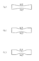
なお、前記膨出部614,624は弧状に膨らんだ形状のものとしたが、その他の形状とすることも可能である。例えば、図8(a)に示すように中央部が尖った尖形のものとしてもよい。また、イメージセンサ51の出力レベルに主に影響を与える部位が結像レンズ50全域ではなく中央部付近の一部である場合等では、図8(b)、(c)に示すように、前記切欠部612及び切欠部622の中央付近の一部に膨出部614,624を形成することとしてもよい。
【0029】
また、前述したように、前記上遮光部材61及び下遮光部材62は、爪611,621を嵌入させる基板60の位置決め孔604を変更することにより、容易に上下方向(スリット幅方向)に移動させることができるので、上遮光部材61及び下遮光部材62により形成されるスリット幅を容易に調整することができる。従って、例えば、画像読取装置100の出荷時や設置時、メンテナンス時に、イメージセンサ51の出力レベルが一定となるようにスリット幅を調整することにより、光源21の配光特性、結像レンズ50の周辺光量不足、及びイメージセンサ51の感度等、各々個体間差を補正することができる。
【0030】
なお、本実施の形態では、基板60の複数の位置決め孔604のいずれかに上遮光部材61及び下遮光部材62に突設された爪611,621を嵌入させることとして、上遮光部材61及び下遮光部材62をスリット幅方向に移動可能としたが、例えばラック−ピニオン機構で上遮光部材61及び下遮光部材62を上下方向に移動させる等、他の周知の移動機構を用いることも勿論可能である。
【0031】
なお、前記実施の形態では本画像読取装置100が装備されたコピー・ファクシミリ複合機1を例に説明したが、本発明に係る画像読取装置がスキャナ等の他の装置にも適用でき、また、本実施の形態で示した画像読取装置100の読取ユニット101の構成等も一例であり、本発明の要旨を逸脱しない範囲内において変更可能であることは当然である。
【0032】
【発明の効果】
このように、本発明に係る画像読取装置によれば、絞り機構が、原稿からの反射光を通すための開口部が形成されて結像レンズの前方に設けられる基板と、開口部の一部分を遮蔽するようにして基板に取り付けられる遮光部材とを備え、基板に、遮光部材の取付位置を調整するための複数の位置決め孔が、所定間隔で列設され、且つ、段違い状に複数列形成される一方、遮光部材に、基板のいずれかの列の位置決め孔に嵌入可能な複数の爪が、それぞれ突設されたので、遮光部材の基板への取付位置を、遮光部材の爪の厚み寸法より微細に調整することができる。
【0033】
また、遮光部材が、開口部の上側の一部分を遮蔽する位置調整可能な上遮光部材と、下側の一部分を遮蔽する位置調整可能な下遮光部材とを備えるので、イメージセンサの出力レベルが一定になるように、上遮光部材と下遮光部材によって形成されるスリット幅が調整可能となり、光源、結像レンズ、及びイメージセンサの個体間差を容易且つ簡便に補正することができる。
【図面の簡単な説明】
【図1】コピー・ファクシミリ複合機1の外観を示す概略斜視図である。
【図2】画像読取装置100の構成を示す概略断面図である。
【図3】画像読取ユニット101の主要な構成を示す側面図である。
【図4】スキャナユニット105及び絞り機構106の構成を示す斜視図である。
【図5】絞り機構106の構成を示す分解斜視図である。
【図6】絞り機構106の構成を示す正面図である。
【図7】イメージセンサ51の出力レベルを示す図である。
【図8】スリット形状の変形例を示す図である。
【符号の説明】
100 画像読取装置
106 絞り機構
50 結像レンズ
51 イメージセンサ
61 上遮光部材
62 下遮光部材[0001]
BACKGROUND OF THE INVENTION
The present invention relates to an image reading apparatus that performs image reading by forming an image of reflected light from a document on an image sensor, and in particular, makes the amount of light incident on the image sensor uniform with respect to a decrease in the amount of light around the imaging lens. The present invention relates to an image reading apparatus capable of performing the above.
[0002]
[Prior art]
In scanners, facsimiles, copiers, and the like, generally, a document such as paper placed on a platen glass is scanned under a platen glass with a light source, a reflection mirror, or the like, or an auto document feeder (ADF). The image is read by irradiating the original with light while automatically conveying the original, and forming an image of reflected light from the original on an image sensor such as a CCD.
[0003]
The light source has a variation in light distribution characteristics. For example, when the light source is a rod-shaped light source at the main scanning position (reading line direction), the light amount is not uniform in all the axial directions, and is generally large in the center and near the end. Few. Such a deviation in the amount of light becomes a deviation in the output distribution of the image formed on the image sensor, which is one of the causes for degrading the image reading accuracy. Further, a decrease in the output signal level due to insufficient light quantity at the periphery of the imaging lens has been conventionally amplified electrically by a shading correction circuit.
[0004]
In order to adjust the variation in the light distribution characteristics of the light source as described above, a plurality of light amount adjustment plates are provided in the axial direction of the light source, and light incident on the original from the light source is partially blocked by each light amount adjustment plate. An illumination device has been devised (see Patent Document 1). According to this apparatus, each light quantity adjustment plate can be protruded largely with respect to the center of the light source, and can be protruded small at both ends so that the amount of light incident on the original from the light source can be adjusted to be uniform. In addition, a black printing layer is partially formed at the center of the reflecting surface of the reflector that reflects the light from the light source toward the document to reduce the reflectance, or a notch is provided to reduce the light from the light source to the back of the reflector. A document illuminating device has also been devised that equalizes the amount of light incident on the document from the light source by escaping (see Patent Document 2).
[0005]
[Patent Document 1]
JP 7-319081 A [Patent Document 2]
Japanese Patent Laid-Open No. 8-204906
[Problems to be solved by the invention]
In image reading in a scanner, facsimile, copying machine, etc., reflected light from a document guided to an image sensor by a reflecting mirror or the like is converged on a reading surface of the image sensor by an imaging lens. Even if the amount of light incident on the document by the illuminating device is uniform, the main scanning of the document also occurs due to a lack of light in the peripheral part due to the so-called
[0007]
In addition, if the output of the image sensor is electrically amplified by a shading correction circuit in order to correct the variation in the amount of light incident on the image sensor due to insufficient light quantity at the periphery of the coupling lens, the output signal of the image sensor Is also amplified, so that the dynamic range of the amplified portion is reduced. In particular, for each of RGB in color image reading, for example, when reading is performed with 8 bits and 256 gradations, if shading correction by electrical amplification as described above is performed, the dynamic range of the insufficient light amount portion is reduced. For the same color of the same document, there is a problem that color misregistration occurs at the center and both ends of the document.
[0008]
The present invention has been made in view of these points, and does not cause variations in the amount of light incident on the image sensor due to the light distribution characteristics of the light source or the insufficient amount of light in the periphery of the imaging lens. An object of the present invention is to provide an image reading apparatus capable of correcting easily and simply.
[0009]
[Means for Solving the Problems]
The image reading apparatus according to the present invention, the reflected light from the original by transmitting the imaging lens have line image reading by imaged on the image sensor, the reading light incident on the imaging lens of the image sensor In the image reading apparatus provided with a diaphragm mechanism that restricts corresponding to a line, the diaphragm mechanism is provided with a substrate provided in front of the imaging lens, in which an opening for passing reflected light from a document is formed; A light shielding member attached to the substrate so as to shield a part of the opening, and a plurality of positioning holes for adjusting the attachment position of the light shielding member are arranged in the substrate at predetermined intervals, and While the plurality of rows are formed in a stepwise manner, the plurality of claws that can be fitted into the positioning holes in any row of the substrate are respectively provided on the light shielding member .
[0010]
Further, in the image reading apparatus according to the present invention, the position of the light-shielding member that can be adjusted is such that the light-shielding member shields a part of the upper side of the opening, and the position of the light-shielding member that can be adjusted is such that the part of the lower side is shielded. Is provided .
[0011]
DETAILED DESCRIPTION OF THE INVENTION
Hereinafter, an image reading apparatus according to an embodiment of the present invention will be specifically described with reference to the drawings. Note that the image reading apparatus according to the present embodiment is merely an example of the present invention, and the configuration of the present invention is naturally not limited to the image reading apparatus.
[0012]
FIG. 1 is a schematic perspective view showing an external appearance of an upper part of a copy / facsimile multifunction peripheral 1 including an
[0013]
Although not shown in the figure, the copy / facsimile multifunction peripheral 1 includes a paper feeding unit that supplies recording paper for recording the read image, an image recording unit that records an image on the recording paper, and an image. The copier / facsimile multifunction peripheral 1 is an example of a device including the image reading apparatus according to the present invention, and includes an arbitrary configuration. Of course.
[0014]
FIG. 2 is a view showing a longitudinal section of the reading table 3 and the
[0015]
Below the platen glass 2, when the FBS is used, the original on the platen glass 2 is scanned while moving horizontally below the platen glass 2. When the
[0016]
FIG. 3 is a diagram showing the main configuration of the
[0017]
Further, a pair of
[0018]
The full-
[0019]
FIG. 4 is a schematic perspective view showing a detailed configuration of the
[0020]
As shown in the drawing, an
[0021]
More specifically, the
[0022]
In the present embodiment, a plurality of
[0023]
As described above, the upper
[0024]
On the other hand, similarly to the upper
[0025]
As a result, as shown in the drawing, a horizontally long slit is formed in front of the
[0026]
The slit shape is such that the slit width (vertical direction) is the most sandwiched at the center corresponding to the approximate center of the
[0027]
The shape of the bulging
[0028]
The bulging
[0029]
Further, as described above, the upper
[0030]
In the present embodiment, the upper
[0031]
In the embodiment, the copy / facsimile multifunction peripheral 1 equipped with the
[0032]
【The invention's effect】
As described above, according to the image reading apparatus according to the present invention, the diaphragm mechanism includes the substrate provided in front of the imaging lens in which the opening for allowing the reflected light from the original to pass through is formed, and a part of the opening. And a plurality of positioning holes for adjusting the mounting position of the light shielding member arranged at predetermined intervals and formed in a plurality of rows in a stepwise manner. On the other hand, since the plurality of claws that can be inserted into the positioning holes in any row of the substrate are respectively provided on the light shielding member, the mounting position of the light shielding member on the substrate is determined by the thickness dimension of the light shielding member claws. It can be finely adjusted.
[0033]
Further, since the light shielding member includes a position-adjustable upper light-shielding member that shields a part of the upper side of the opening and a position-adjustable lower light-shielding member that shields a part of the lower side, the output level of the image sensor is constant. Thus, the slit width formed by the upper light shielding member and the lower light shielding member can be adjusted, and the individual differences among the light source, the imaging lens, and the image sensor can be easily and simply corrected.
[Brief description of the drawings]
FIG. 1 is a schematic perspective view showing an external appearance of a copy /
2 is a schematic cross-sectional view showing a configuration of an
3 is a side view showing a main configuration of the
4 is a perspective view showing configurations of a
FIG. 5 is an exploded perspective view showing a configuration of a
6 is a front view showing the configuration of the
7 is a diagram showing an output level of the
FIG. 8 is a diagram showing a modified example of a slit shape.
[Explanation of symbols]
DESCRIPTION OF
Claims (2)
前記絞り機構が、原稿からの反射光を通すための開口部が形成されて前記結像レンズの前方に設けられる基板と、前記開口部の一部分を遮蔽するようにして前記基板に取り付けられる遮光部材とを備え、
前記基板に、前記遮光部材の取付位置を調整するための複数の位置決め孔が、所定間隔で列設され、且つ、段違い状に複数列形成される一方、
前記遮光部材に、前記基板のいずれかの列の位置決め孔に嵌入可能な複数の爪が、それぞれ突設されたことを特徴とする画像読取装置。 There line image reading by imaging the reflected light from the original by transmitting the imaging lens to an image sensor, limiting the light incident on the imaging lens corresponding to the reading line of the image sensor diaphragm mechanism In an image reading apparatus comprising :
The diaphragm mechanism is formed with an opening through which reflected light from the original is passed, and a substrate provided in front of the imaging lens, and a light shielding member attached to the substrate so as to shield a part of the opening. And
On the substrate, a plurality of positioning holes for adjusting the mounting position of the light shielding member are arranged at predetermined intervals, and a plurality of rows are formed in steps.
An image reading apparatus , wherein a plurality of claws that can be inserted into positioning holes in any row of the substrate are provided on the light shielding member .
Priority Applications (1)
| Application Number | Priority Date | Filing Date | Title |
|---|---|---|---|
| JP2002357632A JP4013137B2 (en) | 2002-12-10 | 2002-12-10 | Image reading device |
Applications Claiming Priority (1)
| Application Number | Priority Date | Filing Date | Title |
|---|---|---|---|
| JP2002357632A JP4013137B2 (en) | 2002-12-10 | 2002-12-10 | Image reading device |
Publications (2)
| Publication Number | Publication Date |
|---|---|
| JP2004193839A JP2004193839A (en) | 2004-07-08 |
| JP4013137B2 true JP4013137B2 (en) | 2007-11-28 |
Family
ID=32757577
Family Applications (1)
| Application Number | Title | Priority Date | Filing Date |
|---|---|---|---|
| JP2002357632A Expired - Fee Related JP4013137B2 (en) | 2002-12-10 | 2002-12-10 | Image reading device |
Country Status (1)
| Country | Link |
|---|---|
| JP (1) | JP4013137B2 (en) |
Families Citing this family (3)
| Publication number | Priority date | Publication date | Assignee | Title |
|---|---|---|---|---|
| US8199377B2 (en) | 2005-06-07 | 2012-06-12 | Nippon Sheet Glass Company, Limited | Image sensor and image reading device |
| JP4508973B2 (en) * | 2005-08-02 | 2010-07-21 | 日本板硝子株式会社 | Image sensor and image reading apparatus |
| JP2021196222A (en) * | 2020-06-11 | 2021-12-27 | 東芝テック株式会社 | Sensor unit and image processor |
-
2002
- 2002-12-10 JP JP2002357632A patent/JP4013137B2/en not_active Expired - Fee Related
Also Published As
| Publication number | Publication date |
|---|---|
| JP2004193839A (en) | 2004-07-08 |
Similar Documents
| Publication | Publication Date | Title |
|---|---|---|
| US5280368A (en) | Fixed full width array scan head calibration apparatus | |
| US8755095B2 (en) | Illuminating device, image reading apparatus including the illuinating device, and image forming apparatus including the image reading apparatus | |
| US7391538B2 (en) | Sheet-fed scanner capable of scanning multiple scan lines for image signal calibration | |
| JP2005012783A (en) | Sheet transfer apparatus and image reading apparatus | |
| US8446648B2 (en) | Image reading apparatus and image forming apparatus including the same | |
| JP4467359B2 (en) | Image reading device | |
| JP4013137B2 (en) | Image reading device | |
| US10122886B2 (en) | Image reading device, image forming apparatus provided therewith, and method for controlling image reading device | |
| US10754164B2 (en) | Image reading apparatus and reading module | |
| JP4584198B2 (en) | Measuring apparatus, document reading apparatus, and image forming apparatus | |
| EP1126692B1 (en) | Multiple resolution scanner with improved lamp intensity monitoring capabilities | |
| JP4013136B2 (en) | Image reading device | |
| JP4869840B2 (en) | Image reading apparatus and adjustment method | |
| JP7159862B2 (en) | Image reader | |
| US20060082839A1 (en) | System for processing image signals from an image scanner having a platen and a document handler | |
| JP3721930B2 (en) | Image reading device | |
| JP3885796B2 (en) | Image reading device | |
| JP3801981B2 (en) | Image reading device | |
| JP2009128728A (en) | Light source device, image-reading device, and image-forming device | |
| JP2007306054A (en) | Image reading apparatus | |
| JP2006245904A (en) | Image reading apparatus | |
| JP3871139B2 (en) | Image reading device | |
| JP3922456B2 (en) | Image reading device | |
| JPH04314256A (en) | Picture reader | |
| JP3634188B2 (en) | Image reading device |
Legal Events
| Date | Code | Title | Description |
|---|---|---|---|
| A621 | Written request for application examination |
Free format text: JAPANESE INTERMEDIATE CODE: A621 Effective date: 20051018 |
|
| A977 | Report on retrieval |
Free format text: JAPANESE INTERMEDIATE CODE: A971007 Effective date: 20070619 |
|
| A131 | Notification of reasons for refusal |
Free format text: JAPANESE INTERMEDIATE CODE: A131 Effective date: 20070626 |
|
| A521 | Written amendment |
Free format text: JAPANESE INTERMEDIATE CODE: A523 Effective date: 20070718 |
|
| TRDD | Decision of grant or rejection written | ||
| A01 | Written decision to grant a patent or to grant a registration (utility model) |
Free format text: JAPANESE INTERMEDIATE CODE: A01 Effective date: 20070816 |
|
| A61 | First payment of annual fees (during grant procedure) |
Free format text: JAPANESE INTERMEDIATE CODE: A61 Effective date: 20070829 |
|
| FPAY | Renewal fee payment (event date is renewal date of database) |
Free format text: PAYMENT UNTIL: 20100921 Year of fee payment: 3 |
|
| R150 | Certificate of patent or registration of utility model |
Free format text: JAPANESE INTERMEDIATE CODE: R150 |
|
| FPAY | Renewal fee payment (event date is renewal date of database) |
Free format text: PAYMENT UNTIL: 20110921 Year of fee payment: 4 |
|
| FPAY | Renewal fee payment (event date is renewal date of database) |
Free format text: PAYMENT UNTIL: 20110921 Year of fee payment: 4 |
|
| FPAY | Renewal fee payment (event date is renewal date of database) |
Free format text: PAYMENT UNTIL: 20120921 Year of fee payment: 5 |
|
| FPAY | Renewal fee payment (event date is renewal date of database) |
Free format text: PAYMENT UNTIL: 20130921 Year of fee payment: 6 |
|
| LAPS | Cancellation because of no payment of annual fees |