JP4011564B2 - Optical fiber connector cleaner and optical fiber connector connection surface cleaning method - Google Patents
Optical fiber connector cleaner and optical fiber connector connection surface cleaning method Download PDFInfo
- Publication number
- JP4011564B2 JP4011564B2 JP2004196711A JP2004196711A JP4011564B2 JP 4011564 B2 JP4011564 B2 JP 4011564B2 JP 2004196711 A JP2004196711 A JP 2004196711A JP 2004196711 A JP2004196711 A JP 2004196711A JP 4011564 B2 JP4011564 B2 JP 4011564B2
- Authority
- JP
- Japan
- Prior art keywords
- cleaning
- optical fiber
- rod
- housing
- tape
- Prior art date
- Legal status (The legal status is an assumption and is not a legal conclusion. Google has not performed a legal analysis and makes no representation as to the accuracy of the status listed.)
- Active
Links
Images


Description
本発明は、光通信機器等に組み込まれている光ファイバコネクタのフェルール端面(接続端面)を清掃するために用いられるクリーナに関するもので、詳しくは、アダプタが装着された状態の光ファイバコネクタのフェルール端面を清掃するに好適なクリーナに関する。 The present invention relates to a cleaner used for cleaning a ferrule end face (connection end face) of an optical fiber connector incorporated in an optical communication device or the like, and more specifically, the ferrule of an optical fiber connector with an adapter attached thereto. The present invention relates to a cleaner suitable for cleaning an end face.
光通信機器に関わる機器類に組み込まれている光ファイバコネクタは、接続と切り離しが高い頻度で行われる。そのため、切り離した際に埃や油脂等が光ファイバコネクタの端面に付着して、伝送性能の低下を招くことがある。そこで、光ファイバコネクタを着脱した際に、そのフェルール端面の清掃が行われる。 Optical fiber connectors incorporated in devices related to optical communication devices are frequently connected and disconnected. For this reason, dust, oil or the like may adhere to the end face of the optical fiber connector when it is cut off, resulting in a decrease in transmission performance. Therefore, when the optical fiber connector is attached / detached, the ferrule end face is cleaned.
しかし、着脱される側、即ち、挿入される側(雄側)のコネクタは、清掃する端面が露出しているため比較的容易に清掃できるものの、機器に組み込まれた受け手側(雌側)のコネクタは、接続用のアダプタなどが取り付けられているため清掃する端面が奥まった位置にあり、清掃が難しいという問題がある。このため、清掃具について様々な提案がされているが、実用に供することができるような清掃性に優れたものがなく、通常は棒状の先端に清掃用の繊維を巻きつけた綿棒のようなものが使用されている。
しかし、綿棒のような清掃具の場合、個人によるバラツキや清掃毎のバラツキが出て均一な清掃が困難であること、光通信機器のような大量のコネクタが組み込まれた装置では清掃に多くの時間が掛かること、清掃の際に清掃用の繊維が脱落して挿入損失の増大を招くおそれがあること等の問題がある。 However, in the case of a cleaning tool such as a cotton swab, it is difficult to perform uniform cleaning due to individual variations and variations from cleaning to cleaning, and devices that incorporate a large number of connectors such as optical communication devices are often used for cleaning. There are problems such as taking time and cleaning fibers falling off during cleaning, which may increase insertion loss.
そこで、本発明は、操作性、清掃性に優れると共に、光ファイバコネクタのオス端子とメス端子の両方の清掃が確実に行える光ファイバコネクタ用クリーナの提供を目的とする。 Accordingly, an object of the present invention is to provide an optical fiber connector cleaner that is excellent in operability and cleanability, and that can reliably clean both the male terminal and the female terminal of the optical fiber connector.
本願発明による光ファイバコネクタ用クリーナは、ハウジングと、前記ハウジング内部に配置された清掃テープの巻き取り手段および送り出し手段と、前記ハウジングの外側に突出する棒状の清掃部を有する清掃手段であって、前記清掃部の先端に、前記送り出し手段から送り出された前記清掃テープが露出した状態で前進移動可能に張架され、前記清掃部の先端を前記光ファイバコネクタの端面に接触させて前記端面を清掃する清掃手段と、前記ハウジング内部において、前記清掃部に対して同軸に接続され、かつ前記ハウジングに対して回転自在に支承される清掃部回転手段と、前記巻き取り手段及び前記清掃部回転手段をほぼ同時にそれぞれ所定の方向に所定の角度回転させた後、前記清掃部回転手段を元の位置まで反転させる伝動手段と、を備える。 An optical fiber connector cleaner according to the present invention is a cleaning unit having a housing, a winding unit and a feeding unit for a cleaning tape disposed inside the housing, and a rod-shaped cleaning unit protruding outside the housing, The tip of the cleaning unit is stretched so as to be able to move forward with the cleaning tape delivered from the delivery means exposed, and the end of the cleaning unit is brought into contact with the end surface of the optical fiber connector to clean the end surface. A cleaning unit that is coaxially connected to the cleaning unit and rotatably supported with respect to the housing, and the winding unit and the cleaning unit rotation unit. A transmission hand that rotates the cleaning unit rotating means to its original position after rotating it by a predetermined angle in a predetermined direction almost simultaneously. And, equipped with a.
または、本願発明の光ファイバコネクタ用クリーナは、ハウジングと、前記ハウジング内部に装着された清掃テープの巻き取り手段および送り出し手段と、前記ハウジングの外側に突出する棒状の清掃部を有する清掃手段であって、前記清掃部の先端に、前記送り出し手段から送り出された前記清掃テープが露出した状態で前進移動可能に張架され、前記清掃部の先端を前記光ファイバコネクタの端面に接触させて前記端面を清掃する清掃手段と、前記ハウジング内部において、前記清掃部に対して同軸に接続され、かつ前記ハウジングに対して回転自在に支承される清掃部回転手段と、前記清掃部に対して同軸に接続され、かつ前記ハウジングに対して回転自在に支承される清掃テープのガイド手段と、前記巻き取り手段及び前記清掃部回転手段をほぼ同時にそれぞれ所定の方向に所定の角度回転させた後、前記清掃部回転手段を元の位置まで反転させる伝動手段と、を備える。 Alternatively, an optical fiber connector cleaner according to the present invention is a cleaning means having a housing, a winding means and a feeding means for a cleaning tape mounted inside the housing, and a rod-shaped cleaning portion protruding outside the housing. The end of the cleaning unit is stretched so as to be movable forward in a state where the cleaning tape sent out from the sending means is exposed, and the end of the cleaning unit is brought into contact with the end face of the optical fiber connector. A cleaning means for cleaning the cleaning part, a cleaning part rotating means coaxially connected to the cleaning part and rotatably supported with respect to the housing, and coaxially connected to the cleaning part. And a cleaning tape guide means rotatably supported with respect to the housing, the winding means and the cleaning portion rotation After approximately by the respective rotating a predetermined angle in a predetermined direction at the same time the means, and a transmission means for inverting the cleaning section rotating means to its original position.
好ましくは、前記伝動手段は、前記巻き取り手段及び送り出し手段と清掃部回転手段とをほぼ同時に回転させる。 Preferably, the transmission means rotates the winding means, the feeding means, and the cleaning unit rotating means almost simultaneously.
好ましくは、前記清掃部が、中空の棒状部材と、前記棒状部材の先端に配置された滑り性の良い部材と、を備える。 Preferably, the cleaning unit includes a hollow bar-shaped member and a member having good slipperiness disposed at a tip of the bar-shaped member.
好ましくは、前記清掃部が、中空の棒状部材と、前記棒状部材の先端に回転自在に装着されたローラと、を有する。 Preferably, the cleaning unit includes a hollow bar-like member and a roller rotatably attached to the tip of the bar-like member.
好ましくは、前記清掃部の主要部が中実の棒状部材である。 Preferably, the main part of the cleaning part is a solid bar-like member.
好ましくは、前記清掃テープは、毛羽立ち防止処理が施された布である。 Preferably, the cleaning tape is a cloth subjected to a fuzz prevention treatment.
前記清掃テープは、毛羽立ち防止処理が施された織布であってもよい。 The cleaning tape may be a woven fabric that has been subjected to fluff prevention treatment.
好ましくは、前記伝動手段は、鉛直方向に昇降するアームを備え、前記アームの下降運動により前記巻き取り手段を第1の方向に第1の角度回転させると同時に、前記清掃部回転手段を第2の方向に第2の角度回転させ、かつ前記アームの上昇運動により前記清掃部回転手段を前記第2の方向と反対に前記第2の角度回転させるように構成されている
好ましくは、前記伝動手段は、鉛直方向に昇降するアームを備え、前記アームの下降運動により前記巻き取り手段を第1の方向に第1の角度回転させかつ前記清掃部回転手段を第2の方向に第2の角度回転させると同時に、前記送り出し手段を第3の方向に前記第1の角度回転させ、かつ前記アームの上昇運動により前記清掃部回転手段を前記第2の方向と反対に前記第2の角度回転させるように構成されている。
Preferably, the transmission unit includes an arm that moves up and down in a vertical direction, and the winding unit rotates at a first angle in a first direction by the downward movement of the arm, and at the same time, the cleaning unit rotation unit is moved to the second direction. Preferably, the transmission means is rotated by a second angle in the direction of the rotation of the arm, and the cleaning section rotation means is rotated by the second angle opposite to the second direction by the upward movement of the arm. Comprises an arm that moves up and down in the vertical direction, and by the downward movement of the arm, the winding means is rotated by a first angle in the first direction, and the cleaning unit rotating means is rotated by a second angle in the second direction. At the same time, the delivery means is rotated by the first angle in a third direction, and the cleaning section rotating means is rotated by the second angle opposite to the second direction by the upward movement of the arm. It is configured as follows.
好ましくは、前記伝動手段のアームは、その長手方向に沿って形成された複数の切欠きを有し、前記清掃部回転手段は、その外周面に設けられた複数の突起を有し、前記アームが下降運動するとき、前記アームの切欠きにより前記清掃部回転手段の突起が順次押し下げられ、前記清掃部回転手段が所定の方向に所定の角度回転し、前記アームが上昇運動するとき、前記アームの切欠きにより前記清掃部回転手段の突起が順次押上げられ、前記清掃部回転手段が前記所定の方向と反対に所定の角度回転する。 Preferably, the arm of the transmission means has a plurality of notches formed along a longitudinal direction thereof, and the cleaning unit rotating means has a plurality of protrusions provided on an outer peripheral surface thereof, and the arm When the arm moves downward, the protrusions of the cleaning unit rotating means are sequentially pushed down by the notch of the arm, and when the cleaning unit rotating means rotates by a predetermined angle in a predetermined direction, the arm moves upward. The protrusions of the cleaning unit rotating means are sequentially pushed up by the notches, and the cleaning unit rotating means rotates by a predetermined angle opposite to the predetermined direction.
好ましくは、前記伝動手段のアームは、複数の切欠き溝を有するラックを有し、前記清掃部回転手段は、前記ラックに噛み合う複数の歯を有するピニオンを有し、前記アームの上昇または下降運動により前記清掃部回転手段が所定の方向またはその反対方向に回転するように構成されている。 Preferably, the arm of the transmission means includes a rack having a plurality of cutout grooves, and the cleaning unit rotating means includes a pinion having a plurality of teeth meshing with the rack, and the arm is moved up or down. Thus, the cleaning unit rotating means is configured to rotate in a predetermined direction or in the opposite direction.
本願発明による光ファイバコネクタのフェルール端面の清掃方法は、清掃テープの表面を光ファイバコネクタのフェルール端面に接触させる工程と、前記清掃テープをその長手方向に一定の距離だけ移動させる工程と、前記清掃テープが移動している間に、前記清掃テープを前記光ファイバコネクタの接続面上で回転させる工程と、を有する。 The method for cleaning the ferrule end face of the optical fiber connector according to the present invention includes the step of bringing the surface of the cleaning tape into contact with the ferrule end face of the optical fiber connector, the step of moving the cleaning tape by a predetermined distance in the longitudinal direction, and the cleaning Rotating the cleaning tape on the connection surface of the optical fiber connector while the tape is moving.
または、本願発明による光ファイバコネクタのフェルール端面の清掃方法は、清掃テープが移動可能に張架される清掃部の先端を光ファイバコネクタに挿入する工程と、前記清掃部の先端の清掃テープを前記光ファイバコネクタのフェルール端面に接触させる工程と、前記清掃テープを前記フェルール端面に接触させている間に、前記清掃テープを移動させると同時に回転させる工程と、を有する。 Alternatively, the method for cleaning the ferrule end face of the optical fiber connector according to the present invention includes the step of inserting the tip of the cleaning portion on which the cleaning tape is movably stretched into the optical fiber connector, and the cleaning tape at the tip of the cleaning portion. And a step of bringing the cleaning tape into contact with the ferrule end surface, and a step of rotating the cleaning tape simultaneously with moving the cleaning tape while the cleaning tape is in contact with the ferrule end surface.
または、光ファイバコネクタ用クリーナは、片手で持てる大きさに形成されたハウジングと、前記ハウジングの先端に設けられた、延伸軸を有する棒状の清掃部と、前記ハウジング内に配置された巻き取り手段及び送り出し手段と、前記送り出し手段から繰り出され前記清掃部の先端に掛け回わされた後、前記巻き取り手段に巻き取られる清掃テープと、前記清掃部を前記延伸軸を中心に所定量回転させる清掃部回転手段と、前記巻き取り手段を駆動すると同時に前記清掃部回転手段を駆動する手動操作部と、を有し、前記清掃部は、前記清掃テープが側面および先端部に掛け回わされた棒状の内側ガイド部材と、前記内側ガイド部材の先端を露出させた状態で前記内側ガイド部材及び清掃テープの外周を取囲む外側ガイド部材と、を有し、内側ガイド部材及び外側ガイド部材はそれぞれ独立して前記先端の方向に付勢されている。 Alternatively, the optical fiber connector cleaner includes a housing formed to have a size that can be held by one hand, a rod-shaped cleaning portion having an extending shaft provided at the front end of the housing, and winding means disposed in the housing. And a feeding means, a cleaning tape that is fed from the feeding means and wound around the tip of the cleaning portion, and then wound around the winding means, and the cleaning portion is rotated by a predetermined amount around the extension shaft. A cleaning unit rotating unit; and a manual operation unit that drives the cleaning unit rotating unit at the same time as driving the winding unit, and the cleaning unit is configured such that the cleaning tape is wound around the side surface and the front end unit. A rod-shaped inner guide member, and an outer guide member that surrounds the outer periphery of the inner guide member and the cleaning tape with the tip of the inner guide member exposed, Side guide member and the outer guide member is biased in the direction of the distal end independently.
好ましくは、清掃部は、基端部において、ハウジングに設けられた軸に支持され、前記軸を支点としてハウジングに対して所定の角度旋回可能である。 Preferably, the cleaning portion is supported at a base end portion by a shaft provided in the housing, and is rotatable at a predetermined angle with respect to the housing with the shaft as a fulcrum.
好ましくは、前記清掃部に着脱自在に装着可能なカバーをさらに有し、前記カバーはオス側端子が挿入されるのに適合された挿入孔を備えた筒状部を有する。 Preferably, the cover further includes a cover that can be detachably attached to the cleaning portion, and the cover includes a cylindrical portion having an insertion hole adapted to receive a male terminal.
好ましくは、前記カバーは、前記挿入孔を覆うキャップをさらに有する。 Preferably, the cover further includes a cap that covers the insertion hole.
または、光ファイバコネクタ用クリーナは、ハウジングと、前記ハウジングの一端に設けられた清掃部であって、棒状部材を有し、前記棒状部材はその延伸軸を中心として回転可能に前記ハウジングに支持され、前記棒状部材の先端には、清掃テープが露出した状態でテープ長さ方向に移動可能に支持される清掃部と、前記ハウジングに設けられた移動可能な操作部と、前記棒状部材および前記操作部に結合され、前記操作部の移動に応じて前記棒状部材を前記延伸軸を中心として回転させる清掃部回転駆動手段と、前記操作部に結合され、前記操作部の移動に応じて前記清掃テープを巻き取り、前記棒状部材の先端において前記清掃テープを前進させる巻き取り手段と、を有する。 Alternatively, the optical fiber connector cleaner is a housing and a cleaning portion provided at one end of the housing, and has a rod-like member, and the rod-like member is supported by the housing so as to be rotatable about its extending axis. The cleaning member supported to be movable in the tape length direction with the cleaning tape exposed at the tip of the rod-shaped member, the movable operation portion provided in the housing, the rod-shaped member, and the operation A cleaning unit rotation driving unit coupled to the operation unit and configured to rotate the rod-shaped member around the extending axis according to the movement of the operation unit; and the cleaning tape coupled to the operation unit and according to the movement of the operation unit. Winding means for advancing the cleaning tape at the tip of the rod-shaped member.
好ましくは、前記清掃部回転駆動手段は、前記操作部の第1の移動により、前記棒状部材を前記延伸軸回りの順方向に回転させ、前記操作部の第2の移動により、前記棒状部材を逆方向へ回転させて元の位置に戻し、前記巻き取り手段は、前記ハウジングに回転可能に支持されて前記清掃テープを巻き取る巻き取り部を有し、前記巻き取り部は、前記操作部の第1および第2の移動のどちらによっても、所定の回転方向へ回転して前記清掃テープを巻き取り、前記棒状部材の先端において前記清掃テープを前進させる。 Preferably, the cleaning unit rotation driving means rotates the rod-shaped member in a forward direction around the extending axis by the first movement of the operation unit, and causes the rod-shaped member to be rotated by the second movement of the operation unit. Rotating in the reverse direction to return it to its original position, the winding means has a winding portion that is rotatably supported by the housing and winds the cleaning tape, and the winding portion is a portion of the operation portion. By either the first movement or the second movement, the cleaning tape is wound up by rotating in a predetermined rotation direction, and the cleaning tape is advanced at the tip of the rod-shaped member.
好ましくは、前記清掃部回転駆動手段は、前記棒状部材の基端に設けられたピニオンと、
前記操作部に設けられ、前記ピニオンと噛み合うラックと、を含む。
Preferably, the cleaning unit rotation driving means includes a pinion provided at a base end of the rod-shaped member,
A rack that is provided in the operation unit and meshes with the pinion.
好ましくは、前記巻き取り手段は、前記ハウジングに設けられた軸に回転可能に支持されて前記清掃テープを巻き取る巻き取り部と、前記軸の延伸方向において前記巻き取り部の両側に配置され、前記軸に回転可能に支持される第1の回転駆動板および第2の回転駆動板と、前記巻き取り部と第1回転駆動板の間に設けられた第1のラチェット機構と、前記巻き取り部と第2回転駆動板の間に設けられた第2のラチェット機構と、を有し、前記第1および第2のラチェット機構は、前記軸を中心とする第1の回転方向の回転のみを前記巻き取り部に伝達する。 Preferably, the winding means is disposed on both sides of the winding portion in the extending direction of the shaft, and a winding portion that is rotatably supported by a shaft provided in the housing and winds the cleaning tape. A first rotary drive plate and a second rotary drive plate that are rotatably supported by the shaft; a first ratchet mechanism provided between the winding unit and the first rotary drive plate; and the winding unit; A second ratchet mechanism provided between the second rotation drive plates, wherein the first and second ratchet mechanisms only rotate in the first rotation direction about the axis. To communicate.
好ましくは、前記巻き取り手段は、前記操作部の移動に応じて移動する可動部材を有し、前記可動部材は、前記第1の回転駆動板に設けられた第1のピニオンに噛み合う第1のラックと、前記第2の回転駆動板に設けられた第2のピニオンに噛み合う第2のラックと、を有し、前記第1および第2のラックは、前記操作部の移動に応じて前記第1および第2の回転駆動板を互いに反対の方向に回転させるように、前記第1および第2のピニオンと噛み合う。 Preferably, the winding means has a movable member that moves in accordance with the movement of the operation portion, and the movable member is engaged with a first pinion provided on the first rotary drive plate. A second rack that meshes with a second pinion provided on the second rotary drive plate, and the first and second racks move in response to movement of the operation portion. The first and second rotary drive plates are engaged with the first and second pinions so as to rotate in directions opposite to each other.
好ましくは、前記清掃部回転駆動手段は、前記ピニオンと前記棒状部材を結合するばねを有する。 Preferably, the cleaning unit rotation driving means includes a spring that couples the pinion and the rod-shaped member.
好ましくは、前記清掃部は、前記棒状部材を支持するガイドスリーブを有し、前記ガイドスリーブは、前記ハウジングの長手軸に対する前記延伸軸の角度を変更するように、前記ハウジングに旋回可能に支持される。 Preferably, the cleaning unit includes a guide sleeve that supports the rod-shaped member, and the guide sleeve is pivotally supported by the housing so as to change an angle of the extension shaft with respect to a longitudinal axis of the housing. The
好ましくは、前記清掃部は、前記ハウジングに支持された筒状のガイドスリーブと、前記ガイドスリーブの内側面に前記延伸軸に沿って摺動可能に支持され、前記棒状部材と清掃テープを前記延伸軸に沿って摺動可能に収容する筒状の外側ガイド部材と、を有し、前記棒状部材は、前記清掃部回転駆動手段からの回転力を受けるように、連結部材を介して前記清掃部回転駆動手段に連結され、前記外側ガイド部材は、前記ガイドスリーブに形成された段部と係合可能な係合部を有し、前記段部と係合部とが係合するように、前記外側ガイド部材と前記棒状部材の間に設けたばねにより、前記延伸軸に沿って前記棒状部材の先端方向に付勢される。 Preferably, the cleaning unit is supported by the housing in a cylindrical guide sleeve supported by the housing, and is slidably supported on the inner surface of the guide sleeve along the extension shaft, and extends the rod-like member and the cleaning tape. A cylindrical outer guide member that is slidably accommodated along the shaft, and the rod-shaped member receives the rotational force from the cleaning unit rotation driving means via the connecting member. The outer guide member is connected to a rotation driving means, and the outer guide member has an engaging portion engageable with a step portion formed on the guide sleeve, and the step portion and the engaging portion are engaged with each other. The spring provided between the outer guide member and the rod-shaped member is urged in the distal direction of the rod-shaped member along the extending axis.
好ましくは、前記清掃部は、前記ハウジングに支持された筒状のガイドスリーブと、前記ガイドスリーブの内側面に前記延伸軸に沿って摺動可能に支持され、前記棒状部材と清掃テープを前記延伸軸に沿って摺動可能に収容する筒状の外側ガイド部材と、前記延伸軸を中心として回転可能に前記ガイドスリーブの基部に支持されたロータリージョイントであって、前記棒状部材の基端と前記延伸軸に対する周方向において互いに不動に且つ前記延伸軸に沿って摺動可能に係合するロータリージョイントと、を有し、前記ロータリージョイントは、前記清掃部回転駆動手段からの回転力を受けるように、連結部材を介して前記清掃部回転駆動手段に連結され、前記棒状部材は、前記ガイドスリーブに設けられた係合部と係合可能な棒状部材フランジを有し、前記棒状部材フランジが前記係合部と係合するように、前記棒状部材フランジと前記ロータリージョイントの間に設けられたばねにより、前記延伸軸に沿って前記棒状部材の先端方向に付勢され、前記外側ガイド部材は、前記ガイドスリーブに形成された段部と係合可能な外側ガイド部材フランジを有し、前記外側ガイド部材フランジが前記段部と係合するように、前記外側ガイド部材フランジと前記ガイドスリーブの係合部の間に設けられたばねにより、前記延伸軸に沿って前記棒状部材の先端方向に付勢される。 Preferably, the cleaning unit is supported by the housing in a cylindrical guide sleeve supported by the housing, and is slidably supported on the inner surface of the guide sleeve along the extension shaft, and extends the rod-like member and the cleaning tape. A cylindrical outer guide member that is slidably accommodated along an axis, and a rotary joint that is supported on a base portion of the guide sleeve so as to be rotatable about the extension shaft, the proximal end of the rod-like member and the And a rotary joint that is slidably engaged with each other in the circumferential direction with respect to the extending axis, and the rotary joint receives a rotational force from the cleaning unit rotation driving means. The rod-shaped member is connected to the cleaning portion rotation driving means via a connecting member, and the rod-shaped member is engageable with an engaging portion provided on the guide sleeve. And a spring provided between the rod-shaped member flange and the rotary joint so that the rod-shaped member flange engages with the engaging portion. The outer guide member is biased and has an outer guide member flange engageable with a step portion formed on the guide sleeve, and the outer guide member flange is engaged with the step portion. The spring provided between the guide member flange and the engaging portion of the guide sleeve is urged in the distal direction of the rod-shaped member along the extending axis.
好ましくは、前記ハウジングは細長い形状を有する。 Preferably, the housing has an elongated shape.
好ましくは、前記清掃部回転駆動手段は、前記棒状部材および前記操作部に機械的に結合され、前記巻き取り手段は、前記操作部に機械的に結合される。 Preferably, the cleaning unit rotation driving unit is mechanically coupled to the rod-shaped member and the operation unit, and the winding unit is mechanically coupled to the operation unit.
本願発明によれば、操作性、清掃性に優れると共に、光ファイバコネクタのオス端子とメス端子の両方の清掃が確実に行える光ファイバコネクタ用クリーナを提供することができる。 According to the present invention, it is possible to provide an optical fiber connector cleaner that is excellent in operability and cleanability and that can reliably clean both the male terminal and the female terminal of the optical fiber connector.
第1の実施の形態
図1を参照すると、光ファイバコネクタ用クリーナ1は、長く延びたハウジング10と、ハウジング10の長手方向の一端に取り付けられた清掃手段20と、ハウジング10内に取り付けられた清掃テープ巻き取り手段32および清掃テープ送り出し手段34と、ハウジング10の外側にその操作部が突出する伝動手段40と、を含む。
First Embodiment Referring to FIG. 1, an optical fiber connector cleaner 1 includes a
ハウジング10は、外周に沿って外壁を貫通する孔10a、10b、10cを含む。ハウジング10は、清掃手段20に対応して位置決めされた軸受け11a、11bを含む。ハウジング10は、巻き取り手段32と送り出し手段34に対応して位置決めされた軸12a、12bを含む。ハウジング10は、清掃テープTのガイド用のポスト13a、13b、13c、13dと、巻き取り手段32の回転を送り出し手段34に伝達するためのリンクの働きをする捻りばね35の揺動回転の中心を成す軸受13eと、を含む。ケース10は、側面から突出するブラケット14を有する。ブラケット14は、前記側面に対して傾いたストッパ壁15を含む。
The
清掃テープTには、例えば、トレシー(登録商標)のような極細繊維製の布を用いる。極細繊維は、例えば、毛羽立ちのないポリエステル繊維であり、その規格は、0.06デニール、繊維径約2μmである。極細繊維は、1〜2μmの油膜の中に入り込むので、油汚れも掻き取り可能である。また、清掃テープTの縁部は、加熱裁断処理または超音波切断処理によって毛羽立ちを防止する。 For the cleaning tape T, for example, a cloth made of ultrafine fibers such as Toraysee (registered trademark) is used. The ultrafine fibers are, for example, polyester fibers having no fluff, and the standard is 0.06 denier and the fiber diameter is about 2 μm. Since the ultrafine fibers penetrate into the oil film of 1 to 2 μm, oil stains can be scraped off. Moreover, the edge part of the cleaning tape T prevents fuzz by a heat cutting process or an ultrasonic cutting process.
図4を参照すると、清掃手段20は、清掃部21と、清掃部21と一体のガイド22と、清掃部21及びガイド22を軸線上で支持する清掃部回転手段23と、を含む。
Referring to FIG. 4, the
清掃部21は、アダプタが取り付けられた光ファイバコネクタのフェルール端面(接続端面)を清掃できるように、アダプタ内に挿入可能な寸法である。
The cleaning
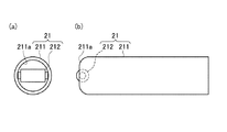
図5、6を参照すると、清掃部21は、中空の円筒(棒状部材)211と、円筒211の先端部において露出する円柱状のローラ212と、を含む。円筒211の先端は、開口211aを有する。円筒211の内壁は、ローラ212を回転可能に支持する。ローラ212の一部は、開口211aから外に突出している(図5参照)。清掃テープTは、ローラ212に張架されて円筒211の先端から露出し、清掃の際、汚れを拭き取る。
Referring to FIGS. 5 and 6, the
図4に示すように、清掃テープのガイド機構22は、円筒21が固定された円形の第1のガイド221と、第1のガイド221から軸方向に隔てられた円形の第2のガイド222と、第1のガイド221と第2のガイド222を同心的に連結する支持軸223と、を含む。
As shown in FIG. 4, the cleaning
第1のガイド221は、支持軸223に対して面対称に形成された矩形の第1の開口221a、221bを有する。第2のガイド222は、支持片223に対して面対称に形成された矩形の第2の開口222a、222bを有する。
The
第2のガイド222a、222bの短辺および長辺は、第1のガイド221a、221bよりも長い。
The short sides and long sides of the
2種類のガイド221、222は、開口221a、221b、222a、222b内における清掃テープTの回転方向の移動を許容する。この移動は、清掃テープTの回転による、軸線周りの清掃テープTの捩れを緩和する。
The two types of
図1において清掃部回転手段23は、回転胴231と、この回転胴231の軸方向両端に接続された回転軸232、235と、を有する。回転軸232、235は、軸受け11a、11bによって回転可能に支持される。回転軸232は、支持軸223、および回転胴231と一体に連結されている。回転胴231は、その表面に突出する複数のピン233を有する。ピン233は、後述するアーム412が円弧状を呈し、かつこれが回転中心の周りに揺動する場合は軸線に対して斜めに配置される。
In FIG. 1, the cleaning unit rotating means 23 includes a
清掃テープTの巻き取り手段32は、清掃テープTを巻き取る環状のリール31を含み、送り出し手段34は清掃テープTを送り出す環状のリール33を含む。リール31、33は、軸12a、12bの周りに回転自在に支持される。リール31、33は、それぞれ、リール31、33と一体的に回転可能な第1および第2のラチェット32A、34Aを含む。第1のラチェット32Aは、径方向に対して時計方向へ斜めに延びる歯321を有する。第2のラチェット34Aは、径方向に対して反時計方向へ斜めに延びる歯341を有する。
The winding means 32 for the cleaning tape T includes an
巻き取り手段32と送り出し手段34の間には、巻き取り手段32の回転を送り出し手段34に伝達するリンク機構として機能する捻りばね35が設けられている。ばね35は、弾性材料、例えば板ばね材の曲げ加工により形成され、軸受け13eを中心に揺動(Swing)自在に枢着されている。ばね35の両端は、巻き取り手段32のラチェット32Aの歯321および送り出し手段34のラチェット34Aの歯341とそれぞれ係合する。
A
より詳細には、巻き取り手段32のラチェット32Aが捻りばね35の一端を時計方向に1ピッチ揺動させると、捻りばね35の他端が送り出し手段34のラチェット34Aを1ピッチ反時計方向に回転させる。また、ばね35は、巻き取り手段32および送り出し手段34の逆回転を防止する。
More specifically, when the
伝動手段40は、作業者の握力が加えられるハンドル41を含む。ハンドル41は基端を有するレバー411と、レバー411の先端から垂直方向に延びる円弧状に湾曲したアーム412と、を含む。レバー411の基端は、ピボット413を使用して、ブラケット14に回転自在に取り付けられる。
The transmission means 40 includes a
アーム412の先端は、互いに離れた2つの切欠き412a、412bを有する。切欠き412a、412bは、それぞれアーム412の反対の側面から横切るように延びる。切欠き412a、412bは、清掃部回転手段23のピン233と係合する。この切り欠き412a、412bとピン233との係合により、清掃部回転手段23に連結された清掃部23を回転し、清掃部21に掛けられた清掃テープTに回転運動を与えることができる。ピン233の数とアーム412の切欠きの数は回転胴231の外径の大きさによって任意の数に選択され得る。
The tip of the
伝動手段40は、板ばね材がブラケット14上のポスト14aに巻きつけられ曲げ加工された捻りばね43を含む。ばね43の一端43aは、第1ラチェット32の歯321と係合する。ラチェット32の歯321とばね43の係合により、巻き取りリール31および送り出しリール33を回転し、清掃テープTを走行させることができる。
The transmission means 40 includes a
ばね43の他端43bは、ケース10の側面に付勢される。ばね43は、先端部分43cで略直角に曲げられる。ばね43は、先端部分43cとポスト14aの間で、レバー411に接している。ばね43により付勢されたレバー411がストッパ壁15に当たって止まり、ハンドル41が原位置に位置決めされる。
The
図7を参照して、クリーナ1の使用方法を説明する。 The usage method of the cleaner 1 is demonstrated with reference to FIG.
例えば、アダプタが取り付けられた光ファイバコネクタを清掃する場合、先ず、清掃部21をアダプタ内に挿入し、ローラ212上の清掃テープTを光ファイバコネクタのフェルール端面に接触させる。
For example, when cleaning the optical fiber connector to which the adapter is attached, first, the
次に、図7(a)に示すように、ハンドル41を鉛直方向に押し下げる。これにより、レバー411は、ピボット413を中心に、反時計方向A1に回転する。この回転により、ハンドル41のアーム412は、孔10bの中へ進み、捻りばね43は孔10cの中へ進む。
Next, as shown in FIG. 7A, the
このとき、巻き取りリール31のラチェット32Aに係合する捻りばね43によって、巻き取りリール31が反時計方向R1に回転する。同時に、この巻き取りリール31の回転により、巻き取りリール31のラチェット32Aと送り出しリール33のラチェット34Aに係合する捻りばね35が時計方向に回転し、送り出しリール33が反時計方向R2に回転する。
At this time, the take-
巻き取りリール31の回転と送り出しリール33の回転により、清掃テープTが送り出しリール33から繰り出され、巻き取りリール31へ巻き取られる。
By the rotation of the take-
より詳細には、清掃テープTは、ポスト13a、13bを経て、第2テープガイド222のガイド溝222bと第1テープガイド221のガイド溝221bを通り、清掃部21に向かって前進する。さらに、清掃テープTは、清掃部21先端のローラ212で折り返し、第1テープガイド221のガイド溝221a、第2テープガイド222のガイド溝222aを通り、ガイドポスト13c、13dを経て、巻き取りリール31に巻き取られる。
More specifically, the cleaning tape T passes through the
一方、上記ハンドル41の押し下げにほぼ同期して、清掃部21の円筒211を支持する清掃部回転手段23のノックピン233が、ハンドル412の切欠き412a、412bの上側に順次係合して、清掃部21を所定の角度、軸回転させる。これにより、清掃テープTは、一定の長さ走行・回転しながらフェルール端面を清掃する。
On the other hand, in synchronism with the depression of the
図7(b)を参照して、清掃後、ハンドル41を解放すると、捻りばね43の反発力によって、ノックピン233がハンドル412の先端側の切欠き412a、412bの下側に、順次係合して、所定の角度、反転してテープTの捻りを解放する。
Referring to FIG. 7B, when the
ハンドル41を解放したとき、捻りばね43は巻き取りリール31に対して反転方向の力を加えるが、巻き取りリール31は捻りばね35により反転が防止されている。このため、捻りばね43の先端43aは、時計方向にラチェット32の歯321をスキップして元の状態に戻る。巻き取りリール31が反転せずに静止しているため、捻りばね35により、送り出しリール33も静止している。したがって、ハンドル41を解放しても張架されている清掃テープTにはたるみが生じない。
When the
以上のクリーナ1によれば、清掃テープTは、前進しながら回転して、コネクタのフェルール端面の汚れを拭き取る。即ち、清掃部21の先端の清掃面T1は新たな清掃テープに更新されつつ、フェルール端面上で回転するので、フェルール端面は常に清浄な清掃テープで種々の方向から擦られることになる。
According to the cleaner 1 described above, the cleaning tape T rotates while moving forward, and wipes off the dirt on the ferrule end face of the connector. That is, the cleaning surface T1 at the front end of the
このため清掃テープを移動させながら清掃する方式や、清掃テープを回転させて清掃する方式のクリーナに比べて優れた清掃効果を得ることが出来る。 For this reason, it is possible to obtain a cleaning effect superior to a cleaner that cleans while moving the cleaning tape or a cleaner that rotates the cleaning tape and cleans it.
第1の変形の形態
図8は、第1実施形態の清掃部21の中空棒状部材211の先端に装着されるローラ212の他の実施形態を示す。
First Modification FIG. 8 shows another embodiment of the
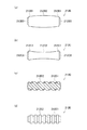
図8(a)に示す樽型形状のローラは、通常の殆どのコネクタのフェルール端面に用いることが出来る。図8(b)に示す鼓型ローラーは、通常のコネクタの中で特に斜め球面研磨されたフェルール端面等において好適に使用できる。 The barrel-shaped roller shown in FIG. 8A can be used on the ferrule end face of most ordinary connectors. The drum-type roller shown in FIG. 8B can be suitably used for a ferrule end face or the like that is polished by an oblique spherical surface in a normal connector.
図8(c)に示すローラ表面に渦巻形の帯状突起を設けたもの、及び、図8(d)に示すローラ表面に所定間隔で円盤状の突起を設けたものは、コネクタ表面に強固に付着した汚れがある場合に好適に使用できる。 The roller surface shown in FIG. 8 (c) provided with spiral belt-like protrusions and the roller surface shown in FIG. 8 (d) provided with disk-like protrusions at predetermined intervals are firmly attached to the connector surface. It can be suitably used when there is attached dirt.
第2の変形の形態
図9は、第1実施形態のガイド22の他の実施形態を示す。
Second Modification FIG. 9 shows another embodiment of the
図9(a)は、清掃部21の棒状部材211の後端に設けた断頭円錐形のガイド部材22Aを示す。図9(b)は、このガイド部材22Aの斜視図である。
FIG. 9A shows a truncated
ガイド部材22Aには、テープをガイドするための扁平な矩形断面を有する貫通孔224A、225Aが設けられている。ガイド孔224A,225Aは清掃手段の棒状部材の後端から、テープの送り出し側と巻き取り側に向けて互いに離隔するように、ガイド部材22Aの軸に対して傾斜して設けられている。これにより、清掃部21の軸回転によって清掃テープに捻りが加えられても、清掃テープが走行するときの摩擦抵抗の増大を防ぐことが出来る。したがって、清掃テープをより円滑に走行させることができる。
The
図9(c)は、他の断頭円錐形のガイド部材22Bを示す。
FIG. 9C shows another
ガイド部材22Bには、ガイド部材22Aと同様に、扁平な矩形断面の貫通孔224B、225Bが設けられ、貫通孔224B、225Bは、テープの送り出し側と巻き取り側に向けて互いに離隔するようにガイド部材22Bの軸に対して傾斜している。貫通孔224B、225Bは、さらに、テープの送り出し側と巻き取り側に向けて断面が拡大しており、これにより、清掃テープが捻られた場合の走行抵抗の増大を防ぐことができる。したがって、清掃テープをより一層円滑に走行させることができる。
Similar to the
第3の変形の形態
図10を参照すると、清掃部21Gは、清掃部回転手段23の回転軸232から延長された中実の棒状体211Gを含む。この棒状体211Gの先端には、清掃テープTが掛けられ、折り返されている。
Third Modification Referring to FIG. 10, the
棒状体211Gの両側側面には、清掃テープ案内溝(図示は省略)が形成され、棒状体211Gは略H字型の横断面を有する。これにより、清掃テープTが前記棒状体211Gの側面に沿って前進する際に、清掃テープTが棒状体211Gの側面から離脱するおそれがない。
Cleaning tape guide grooves (not shown) are formed on both side surfaces of the rod-shaped
第4の変形の形態
図11を参照すると、ハンドル41Aは、ラック413Aを備えた円弧状に湾曲したアーム412Aを含む。清掃部回転手段23Aは、前記ラック413Aと噛み合うピニオン231Aを有する回転胴231Aを含む。アーム412Aが枢着支点413(図1)を中心として揺動する場合、ラック231Aおよびピニオン413Aの歯は、斜めにテーパーをつけられた状態に形成される。
Fourth Modification Referring to FIG. 11, the
第2の実施の形態
図12を参照すると、光ファイバコネクタ用クリーナ1Fは、清掃テープTを前進させる巻き取り手段31Fおよび送り出し手段33Fと、清掃テープTを回転させる清掃手段20Fと、それぞれの機構のアクチュエータと、を含む。
Second Embodiment Referring to FIG. 12, an optical
巻き取り手段31Fは、ハウジング内で軸12F1に回転可能に支持された巻き取り用のリールを含む。送り出し手段33Fは、ハウジング10F内で軸12F2に回転可能に支持された送り出し用のリールを含む。
The winding means 31F includes a winding reel that is rotatably supported by the shaft 12F1 in the housing. The delivery means 33F includes a delivery reel that is rotatably supported by the shaft 12F2 in the
清掃テープTは、ポスト13a、13b、13c、13dによって、ガイドされる。
The cleaning tape T is guided by the
清掃手段20Fは、先端に一体に固定された清掃部21およびガイド22と、ガイド22の支持片223に固定された回転軸25Fと、回転軸25Fに接続された減速用のギアボックス24Fを含む。
The
アクチュエータは、巻き取り手段31F、送り出し手段33Fのそれぞれを駆動するモータM1、M2を含む。巻き取り手段31FとモータM1とは、一対のかさ歯車71、72によって、相互に接続される。送り出し手段33FとモータM2とは、一対のかさ歯車73、74によって、相互に接続される。アクチュエータは、ギアボックス24Fを駆動するモータM3をさらに含む。モータM1、M2、M3は、リード線W1、W2、W3によって、電池Bと電気的に接続される。
The actuator includes motors M1 and M2 for driving the winding means 31F and the feeding means 33F, respectively. The winding means 31F and the motor M1 are connected to each other by a pair of
このクリーナ1Fによれば、モータM1、M2、M3を稼動することによって、巻き取り手段31F、送り出し手段33F、および清掃手段20Fを共に駆動する。 According to this cleaner 1F, the winding means 31F, the delivery means 33F, and the cleaning means 20F are driven together by operating the motors M1, M2, and M3.
清掃テープTが一定の長さだけ前進し、かつ清掃手段20F(清掃部21)が一定の回転角度だけ回転した後、清掃部回転手段20F(清掃部21)は反転するように構成されている。この反転により、清掃部21とポスト13bおよび13cの間の清掃テープTの捻りが開放される。
After the cleaning tape T advances by a certain length and the cleaning means 20F (cleaning part 21) rotates by a certain rotation angle, the cleaning part rotating means 20F (cleaning part 21) is configured to reverse. . By this inversion, the twist of the cleaning tape T between the cleaning
したがって、清掃テープTの清掃面は、前進しながら回転して、光ファイバコネクタの接続面の汚れを拭き取ることができる。 Therefore, the cleaning surface of the cleaning tape T rotates while moving forward, so that the dirt on the connection surface of the optical fiber connector can be wiped off.
第3の実施の形態
図13は、本願発明の第3の実施形態の光ファイバコネクタ用クリーナ501を示す。
Third Embodiment FIG. 13 shows an optical
クリーナ501は、ハウジング503と、ハウジング503の先端に設けた清掃部505と、ハウジング503の上面に設けた上下方向に移動可能な手動操作部535と、を有する。
The cleaner 501 includes a
ハウジング503は、片手で持って使用できるように前後(図13において左右方向)に長く作られ、左右に分解可能となっている。
The
以下、ハウジング503の長手方向をz方向とし、手動操作部535の移動方向をy方向とする。
Hereinafter, the longitudinal direction of the
図14は、ハウジング503を分解した状態のクリーナ501を示す。クリーナ501は、ハウジング503内に、清掃部505の内側ガイド部材507を回転する清掃部回転手段525と、使用済みの清掃テープTを巻き取る巻き取り手段545と、清掃テープTを繰り出す送り出し手段547と、をさらに有する。
FIG. 14 shows the cleaner 501 with the
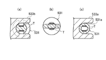
図15は、クリーナ501の前方部分の拡大図であり、清掃部505の縦断面を示す。図16(a)、(b)、(c)は、それぞれ図15の線XVIA、XVIB、XVICに沿って切断された、清掃部505の横断面を示す。
FIG. 15 is an enlarged view of the front portion of the cleaner 501, and shows a longitudinal section of the
図15に示すように、清掃部505は、清掃テープTが掛けられた内側ガイド部材507と、前記内側ガイド部材507と清掃テープTとを取囲む筒状の外側ガイド部材509と、前記外側ガイド部材509を取囲む筒状のガイドスリーブ511と、を含む。
As shown in FIG. 15, the
内側ガイド部材507は、基部507aと、この基部507aから前方(図15において左側)に延伸し清掃部505の先端を成す延伸部507bと、を有する。図16(a)、(b)に示すように、延伸部507bは幅の狭い薄板状に形成されている。これにより、高密度に実装された配線架のコネクタであっても清掃作業を容易に行なうことができる。
The
延伸部507bの先端面は、清掃する光ファイバコネクタのフェルール端面に合わせて、凹球面状に形成されてもよい。これにより、クリーナの清掃性をより向上することができる。
The front end surface of the extending
図15に示すように、清掃テープTは、基部507aの溝508aから、延伸部507bの下側面、先端面、上側面を通って、基部507aの溝508bへと移動可能に掛けられている。清掃テープTは、外側ガイド部材509から突出している延伸部507bの先端においてのみ、外部に露出している。
As shown in FIG. 15, the cleaning tape T is movably hung from the
このように、外側ガイド部材509が内側ガイド部材507及び清掃テープTを覆うことにより、清掃テープTを汚れから保護すると共に、清掃テープTを内側ガイド部材507から外れないよう円滑に走行させることができる。
As described above, the
図16(c)に示すように、内側ガイド部材507の基部507aには、z軸を中心とする径方向に延伸し、外側ガイド部材509のスリット512a、512bと係合する係合部510a、510bが形成されている。スリット512a、512bは、z方向に細長く形成されている。これにより、内側ガイド部材507は、外側ガイド部材509に対して、z軸を中心とする円周方向には回転を規制されながら、z方向にスライドすることができる。
As shown in FIG. 16C, the
図15に示すように、内側ガイド部材507は、基部507aと後述の清掃部回転手段525との間に設けた第1のばね513により前方(矢印B)へ付勢される。外側ガイド部材509は、内側ガイド部材507との間に設けた第2のばね515により、外側ガイド部材509に形成された段部509cとガイドスリーブ511に形成された段部511aとが係合するように、前方(矢印B)へ付勢される。第1のばね513および第2のばねは、コイルばねであり、清掃テープTはこれらのばねの内側を通っている。
As shown in FIG. 15, the
上記構成により、第2のばね515に抗して、外側ガイド部材509を内側ガイド部材507に対して後方にスライドすることにより、内側ガイド部材507の外側ガイド部材509から突出する部分の長さLを延長することができる。これにより、例えば、図23に示すように端子P3が開口の奧にある場合でも、外側ガイド部材509を開口回りの縁に押し当て、内側ガイド部材507の先端を端子P3に接触させ、端子P3を清掃することができる。このとき、内側ガイド部材507の先端面は、第1のばね513の弾力により、端子P3の端面と所定の圧力で接触するため、端子P3に傷をつける恐れがない。
With the above configuration, the length L of the portion of the
再び図15を参照すると、ガイドスリーブ511は、基端部において、ハウジング503に設けた旋回軸517により旋回自在に支持される。
Referring to FIG. 15 again, the
ガイドスリーブ511は、位置決め手段519によりハウジング503に対して所定の角度に位置決めされる。より詳細には、位置決め手段519は、ハウジング503に固定された複数の係合凹部523a、b、c、dと、ガイドスリーブ511の基端部から延伸し、前記係合凹部523a、b、c、dと係合可能な係合凸部521aを有する係合アーム521と、を有する。
The
係合凹部523a、b、c、dは、旋回軸517を中心とする円弧上に所定の角度間隔で配置される。したがって、旋回軸517を支点にガイドスリープ511を旋回させ、係合凸部521aを係合凹部523a、b、c、dの1つと係合させることにより、清掃部505をハウジング503に対して所定の角度に位置決めすることができる。
The engaging recesses 523a, b, c, and d are arranged at predetermined angular intervals on an arc centered on the turning
係合凸部521aを、図15において最上部の係合凹部523aと係合させたとき、清掃部505は、ハウジング503の長手方向zに対して平行に位置決めされる。
When the engaging convex portion 521a is engaged with the uppermost engaging concave portion 523a in FIG. 15, the cleaning
一方、係合凸部521aを、図15において最下部の係合凹部523dと係合させたとき、清掃部505は、図24に示すように、ハウジング503の長手方向zに対して上方に傾いて位置決めされる。このように、清掃部505を所定の角度上向きとすることで、コネクタの端子P1から放射されるレーザが作業者の目に直接入らないように下向きとした端子P4に対しても、正しく接触させることができると共に、容易、かつ、確実に汚れ落しが行なえる。
On the other hand, when the engaging convex portion 521a is engaged with the lowermost engaging
再び図15を参照すると、清掃部回転手段525は、ピニオン527と、このピニオン527と噛み合うラック529と、を含む。
Referring to FIG. 15 again, the cleaning unit rotating means 525 includes a
ピニオン527の軸531は、ハウジング503に設けた軸受533a、bによってz軸周りに回転可能に両端支持されている。
The
ラック529は、手動操作部535(図14)から延伸するア−ム537に設けられ、手動操作部535と共に上下方向(y方向)に移動可能である。
The
ピニオン527とラック529の噛み合いにより、ラック529のy方向の移動量がピニオン527のz軸回りの回転量となる。すなわち、手動操作部535を上方又は下方へ移動させると、ラック529が上方又は下方へ移動し(矢印C)、ピニオン527に正転又は逆転の回転動力が与えられる。
Due to the engagement of the
軸531の、清掃部505側の端部531bには、前述の第1のばね513の一端が固定されている。第1のばね513は、他端が前記内側ガイド部材507の基部507aに固定されている。これにより、第1のばね513は、清掃部回転手段525からの回転動力を内側ガイド部材507に伝達する。即ち、第1のばね513は、内側ガイド部材507を付勢する付勢機能に加えて、清掃部回転手段525からの回転動力を内側ガイド部材507に伝達する回転動力伝達機能を備えている。清掃部回転手段525が第1のばね513を介して内側ガイド部材507に接続されることにより、清掃部505をz軸に対して傾いて位置決めした場合(図24)でも、内側ガイド部材507に回転動力を伝達し、内側ガイド部材507を延伸軸A回りに回転させることができる。
One end of the
図17(a)、21(b)、21(c)は、それぞれ図15の線XVIIA、XVIIB、XVIICに沿って切断された、軸531の各部の断面を示す。
17 (a), 21 (b), and 21 (c) show cross sections of respective portions of the
軸531は、清掃テープTが軸531に沿って移動するように案内する溝や開口を有する。これにより、軸531に沿って互いに逆方向に進む清掃テープTの未使用部分と使用済み部分が互いに接触して絡まることを防止し、清掃テープTをスムースに移動させることができる。
The
再び図14を参照すると、前記手動操作部535は、ハウジング503に設けたガイド部材541により上下方向(y方向)のみ移動可能に支持されると共に、ハウジング503に設けた支持部材544との間の第3のばね543により上方へ付勢されている。これにより、手動操作部535は、第3のばね543に抗して矢印Wに示すように押圧することで下降し、押圧を解除すると第3のばね543により上昇し、元の位置に復帰する。
Referring to FIG. 14 again, the
前記巻き取り手段545は、使用済みの清掃テープTを巻き取る巻き取りリール549を有する。
The winding means 545 includes a winding
図18は、図14の矢印XVIIIの方向から見た巻き取りリール549の分解図である。
FIG. 18 is an exploded view of the take-up
巻き取りリール549は、胴部551と、この胴部551の両サイドに設けた第1の回転フランジ553および第2の回転フランジ555と、を含む。胴部551と第1および第2回転フランジ553、555は、それぞれ、yz面に延在する円盤状の形状を有し、ハウジング503に設けた軸557(図14)に回転自在に支持される。第1回転フランジ553の外側面(胴部551と反対側の面)には第1のピニオン554が設けられ、第2回転フランジ555の外側面には第2のピニオン556が設けられている。
The take-up
胴部551と第1回転フランジ553の間には、第1回転フランジの図14における反時計回りの回転運動のみを胴部551に伝達する第1のラチェット機構559が設けられている。第1ラチェット機構559は、胴部551の第1フランジ553側の側面に設けた複数の歯563と、第1回転フランジ553に設けた、前記歯563と噛み合い可能かつ外側(胴部551の反対側)へ撓み可能な爪565と、を含む。
Between the trunk | drum 551 and the
同様に、胴部551と第2回転フランジ555の間には、第2回転フランジの図14における反時計方向の回転運動のみを胴部551に伝達する第2のラチェット機構561が設けられている。第2ラチェット機構561は、胴部551の第2フランジ555側の側面に設けた複数の歯567と、第2回転フランジ555に設けた、前記歯567と噛み合い可能かつ外側(胴部551の反対側)へ撓み可能な爪569と、を含む。
Similarly, a
再び図14を参照すると、前記巻き取り手段545は、前記巻き取りリール549を回転させる可動フレーム575を有する。可動フレーム575は、前記第1ピニオン554と噛み合う駆動ギアとしての第1のラック571と、前記第2ピニオン556と噛み合う駆動ギアとしての第2のラック573と、を有する。
Referring again to FIG. 14, the winding means 545 has a
可動フレーム575は、ハウジング503に設けたガイドレール(図示せず)により上下方向(y方向)のみにスライド自在に支持される。
The
図19は、図14のXIX−XIX線に沿って切断した部分断面図であり、第1ラック571と第1ピニオン554、第2ラック573と第2ピニオン556の噛み合いを示す。
FIG. 19 is a partial cross-sectional view taken along the line XIX-XIX in FIG. 14 and shows the engagement of the
第1ラック571は第1ピニオン554の前方(図19における左側)の歯と噛み合い、第2ラック573は第2ピニオン556の後方(図19における右側)の歯と噛み合う。より詳細には、図14に示すように、第1ラック571と第1ピニオン554、および、第2ラック573と第2ピニオン556は、互いに軸557を中心として180度回転した位置で噛み合っている。これにより、可動フレーム575と共に第1および第2ラック571、573が上下方向(y方向)へ移動するとき、第1および第2ピニオン554、556は互いに逆方向に回転する。
The
図19と図20(a)および(b)を参照して、前記ラチェット機構559、561の作用を含む、巻き取りリール549の動作を説明する。
The operation of the take-up
図20(a)は、可動フレーム575が下方へ(矢印E)移動するときの動作を示す。
FIG. 20A shows an operation when the
第1ラック571は、第1ピニオン554を介して第1回転フランジ553を反時計回りに回転させる(矢印F)。第2ラック573は、第2ピニオン556を介して第2回転フランジ555を時計回りに回転させる(矢印G)。
The
ところで、胴部551は、前述の第1および第2ラチェット機構559、561により、反時計回りに回転する回転フランジ553、555のみに連れ回る。したがって、胴部551は、第1回転フランジ553に連れ回り、反時計回りに回転する(矢印H)。なお、第2ラチェット機構561の爪569が外側に撓んで歯567を乗り越え、第2回転フランジ555は時計回りに空回りする。
By the way, the
図20(b)は、可動フレーム575が上方へ(矢印I)移動するときの動作を示す。
FIG. 20B shows the operation when the
第1ラック571は、第1ピニオン554を介して第1回転フランジ553を時計回りに回転させる(矢印J)。第2ラック573は第2ピニオン556を介して第2回転フランジ555を反時計回りに回転させる(矢印K)。
The
したがって、胴部551は、反時計回りに回転する第2回転フランジ555に連れ回り、反時計回りに回転する(矢印M)。なお、第1ラチェット機構559の爪565が外側に撓んで歯563を乗り越え、第1回転フランジ553は時計回りに空回りする。
Accordingly, the
したがって、可動フレーム555が上下方向のどちらに移動するときも、胴部551は、図14における反時計回りに回転し、それにより清掃テープTが巻き取られる。
Therefore, regardless of whether the
再び図14を参照すると、巻き取り手段545は、手動操作部535に連動して可動フレーム575を上下方向に移動させるクランクロッド577をさらに有する。
Referring to FIG. 14 again, the winding means 545 further includes a
クランクロッド577は、一端において、ハウジング503に設けた軸579に旋回可能に支持される。クランクロッド577の他端には、ハウジング503内の手動操作部535に設けた長孔539aと係合するピン581が設けられ、クランクロッド577のほぼ中間部位には、可動フレーム575に設けた長孔575aと係合する駆動ピン583が設けられている。長孔539aおよび575aはz方向に長く形成され、クランクロッド577の旋回に伴うピン581および駆動ピン583のz方向の移動を吸収する。
The
手動操作部535が矢印Wに示すように押圧され、第3のばね543の弾力に反して下方に移動するとき、クランクロッド577のピン581が押し下げられ、クランクロッド577は軸579を支点として下方に旋回する。可動フレーム575は、クランクロッド577の駆動ピン583により押し下げられ、下方へ移動する。
When the
押圧が解除され、手動操作部535が第3のばね543の弾力により上方へ移動するとき、クランクロッド577のピン581が押し上げられ、クランクロッド577は軸579を支点として上方に旋回する。可動フレーム575は、クランクロッド577の駆動ピン583により押し上げられ、上方へ移動する。
When the pressing is released and the
上記巻き取り手段545によれば、手動操作部535が押圧されると、可動フレーム575は下方へ移動し、巻き取りリール549の胴部551は第1回転フランジ553と共に反時計回りに回転する。手動操作部535の押圧が解除されると、可動フレーム575は上方へ移動し、巻き取りリール549の胴部551は第2回転フランジ555と共に図14における反時計回りに回転する。
According to the winding means 545, when the
したがって、手動操作部535の押圧および押圧の解除のいずれの操作によっても、清掃テープTが巻き取りリール549に所定量ずつ巻き取られる。
Therefore, the cleaning tape T is wound around the take-up
送り出し手段547は、清掃テープTの未使用部分が巻かれたリール585を含む。リール585は、ハウジング503に設けた軸587に回転可能に支持される。
The delivery means 547 includes a
リール585は、例えば、軸587の外周面に設けた突起(図示せず)や軸587に通してハウジング503とリール585の間に配置したばね(図示せず)等により、回転時に適度な抵抗を受ける。これにより、清掃テープTが必要以上にリール585から送り出され、清掃部505の先端507b等においてたるみが生じるのを防止することができる。
The
清掃テープTは、巻き取りリール549に巻き取られ、リール585から図14の矢印a、b、c、d、eに沿って移動するので、清掃部505の先端には、常に清掃テープTの未使用部分が供給される。
Since the cleaning tape T is wound around the take-up
清掃テープTの使用量及び残量は、ハウジング503に設けた覗き窓589を通して外から確認することができる。
The usage amount and remaining amount of the cleaning tape T can be confirmed from the outside through a
このように構成されたクリーナ501によれば、手動操作部535を押圧操作することで、使用済みの清掃テープTが巻き取り手段545によって巻き取られると共に、送り出し手段547からきれいな清掃テープTが送り出される。従って、常にきれいな清掃テープTによって端子面の汚れを落すことが可能となる。
According to the cleaner 501 configured as described above, the used cleaning tape T is taken up by the take-up means 545 and the clean cleaning tape T is sent out from the sending-out means 547 by pressing the
清掃部505には、図13に示すようなカバー591を着脱自在に装着することができる。カバー591は、取外した時に紛失しないようにバンド592によってハウジング503に結合されることが望ましい。
A
図21は、カバー591が装着された清掃部505の先端を示す。
FIG. 21 shows the tip of the
カバー591は、筒状部595と、筒状部595の先端に着脱可能に取り付けられたキャップ597と、を備える。筒状部595は先端に挿入孔593を有し、挿入孔593は、コネクタの接続端子面がアダプタで包囲されていないオス側端子P1が挿入されるように適合されている。挿入孔593は、キャップ597により覆うことができる。
The
クリーナー501を使用しない時、清掃部505にカバー591の筒状部595を装着し、筒状部595の先端にキャップ597を嵌めることにより、清掃部505の先端507bを汚れから守ることができる。
When the cleaner 501 is not used, the
クリーナー501をオス側端子P1の清掃に使用する場合には、カバー591を清掃部505に装着し、筒状部595からキャップ597を外した状態で、挿入孔593にオス側端子P1を挿入する。これにより、オス側端子P1の端子面を、清掃部505の先端507bの清掃テープTに接触させ、端子面の汚れを落すことができる。
When the cleaner 501 is used to clean the male terminal P 1 , the
第5の変形の形態
図22(a)および(b)は、第5の変形の形態における清掃部605を示す。
Fifth Modification Mode FIGS. 22A and 22B show a
図22(a)を参照すると、この清掃部605は、清掃部回転手段(図示せず)からの回転動力を内側ガイド部材607に伝達するためのばね613と、内側ガイド部材607を前方へ付勢するためのばね617と、を別々に備えている点と、内側ガイド部材607の先端607bが外側ガイド部材609の内側に配置されている点と、が第3実施形態の清掃部505と異なっている。
Referring to FIG. 22A, the
清掃部605は、清掃テープTが掛けられた内側ガイド部材607と、前記内側ガイド部材607および清掃テープTの前方(図22(a)において左側)部分を取囲む筒状の外側ガイド部材609と、前記内側ガイド部材607および清掃テープTと前記外側ガイド部材609の後方部分を取囲む筒状のガイドスリーブ611と、を含む。
The
図示のように、内側ガイド部材607の先端607bは、通常は外側ガイド部材609の内側に位置する。これにより、先端607bの清掃テープTが使用前に汚れるのを防ぐことができる。
As shown in the drawing, the
ガイドスリーブ611内の基端側には、ロータリージョイント619が、内側ガイド部材607の延伸軸Aを中心として回転可能に支持されている。ロータリージョイント619の基端619aには、第1のばね613の一端が固定され、第1のばね613の他端は清掃部回転手段に固定されている。ロータリージョイント619の先端側には、内側ガイド部材607の基部607aの外周と係合する係合部619bが設けられている。
A rotary joint 619 is supported on the proximal end side in the
内側ガイド部材607は、ロータリージョイント619に対して、延伸軸Aの方向にスライドすることができる。また、内側ガイド部材607は、ロータリージョイント619に対して延伸軸Aに対する周方向には不動に係合する。これにより、ロータリージョイント619は、第1のばね613から伝達される回転動力により回転すると共に、内側ガイド部材607を回転させる。
The
ガイドスリーブ611内の中間部には、ストッパー621が固定されている。ストッパー621は、延伸軸Aに垂直な面内に延在する環状部621aを有し、この環状部621aは、ガイドスリーブ内に2つのばね収容孔623、625を画定している。
A
前方にある第1のばね収容孔623には、外側ガイド部材609の基端609aに設けられたフランジ609cが配置されている。外側ガイド部材609は、このフランジ609cがガイドスリーブ611の先端に形成された段部611aに係合するように、フランジ609cとストッパー621の間に設けた第2のばね615により延伸軸Aに沿って前方に付勢される。外側ガイド部材609は、第2ばね615に抗して押圧することにより、ガイドスリーブ611に対して後方にスライドする。
A
後方にある第2のばね収容孔625には、内側ガイド部材607の基部607aと延伸部607bの間に設けたフランジ607cが配置されている。内側ガイド部材607は、このフランジ607cがストッパ−621に係合するように、フランジ607cとロータリージョイント619の間に設けた第3のばね617により延伸軸Aに沿って前方に付勢される。内側ガイド部材607は、この第3のばね617の弾性により、清掃するコネクタ端面に対する押圧力を一定に保つことができる。
A
1つのばねが付勢機能と回転動力伝達機能を備える場合、ばね定数が大きいため、内側ガイド部材先端の押圧力が必要以上に大きくなり、清掃テープTが円滑に走行しないことがある。しかし、上述のように、回転動力を伝達するばね613と、前方へ付勢するばね617を別々に設け、付勢用ばねのばね定数を回転動力伝達用ばねのばね定数より小さくすることにより、清掃テープTを円滑に走行させることができる。
When one spring has an urging function and a rotational power transmission function, since the spring constant is large, the pressing force at the front end of the inner guide member becomes larger than necessary, and the cleaning tape T may not run smoothly. However, as described above, by separately providing the
図22(c)は、アダプタADが装着されている光ファイバコネクタの端面P2を清掃するときの清掃部605を示す。図示のように、外側ガイド部材609がガイドスリーブ611に対して後方にスライドしながら、内側ガイド部材607の先端607bがアダプタADの割スリーブAD1に挿入されている。
FIG. 22 (c) shows a
より詳細には、まず、外側ガイド部材609の先端609bがアダプタADの割スリーブAD1の先端に当接するように清掃部605を位置決めし、端面P2に向かって前進させる。外側ガイド部材609は、割スリーブAD1に押し戻され、第2のばね615を圧縮する。内側ガイド部材607およびガイドスリーブ611は、外側ガイド部材609に対して前方へ移動する。これにより、内側ガイド部材607の先端607bが外側ガイド部材609から突出し、先端607bの清掃テープTがコネクタの端面P2に接触する。
More specifically, first, the
第3実施形態と同様に端面P2を清掃した後、清掃部605をアダプタADから引き離すと、外側ガイド部材609は第2のばね615の付勢により図22(a)に示す位置に戻り、内側ガイド部材607の先端607bは再び外側ガイド部材609の内部に収容される。
After cleaning the end surface P 2 as in the third embodiment, when separating the
このように、内側ガイド部材607の先端607bが外側ガイド部材609の内部に位置するので、使用前に清掃テープTが汚れるのを防ぐと共に、使用時に清掃テープTがコネクタのフェルール端面以外の部分に接触して汚れるのを防ぐことができる。
Thus, since the
以上の説明から明らかなように、本願発明による光ファイバコネクタ用クリーナおよび光ファイバコネクタのフェルール端面の清掃方法の実施形態は、以下の特徴を有する。 As apparent from the above description, the optical fiber connector cleaner and the method for cleaning the ferrule end face of the optical fiber connector according to the present invention have the following features.
(1) 光ファイバコネクタ用クリーナ1は、
ハウジング10と、
前記ハウジング内部に配置された清掃テープTの巻き取り手段32および送り出し手段34と、
前記ハウジングの外側に突出する棒状の清掃部21を有する清掃手段20であって、前記清掃部の先端に、前記送り出し手段から送り出された前記清掃テープが露出した状態で前進移動可能に張架され、前記清掃部の先端を前記光ファイバコネクタの端面に接触させて前記端面を清掃する清掃手段と、
前記ハウジング内部において、前記清掃部に対して同軸に接続され、かつ前記ハウジングに対して回転自在に支承される清掃部回転手段23と、
前記巻き取り手段及び前記清掃部回転手段をほぼ同時にそれぞれ所定の方向に所定の角度回転させた後、前記清掃部回転手段を元の位置まで反転させる伝動手段40と、
を備える。
(1) The optical fiber connector cleaner 1 is
A
A winding
A cleaning means 20 having a rod-
In the housing, a cleaning unit rotating means 23 connected coaxially to the cleaning unit and rotatably supported with respect to the housing;
A transmission means 40 for rotating the winding unit and the cleaning unit rotating unit substantially simultaneously in a predetermined direction at a predetermined angle, and then reversing the cleaning unit rotating unit to the original position;
Is provided.
(2) 光ファイバコネクタ用クリーナ1は、
ハウジング10と、
前記ハウジング内部に装着された清掃テープTの巻き取り手段32および送り出し手段34と、
前記ハウジングの外側に突出する棒状の清掃部21を有する清掃手段20であって、前記清掃部の先端に、前記送り出し手段から送り出された前記清掃テープが露出した状態で前進移動可能に張架され、前記清掃部の先端を前記光ファイバコネクタの端面に接触させて前記端面を清掃する清掃手段と、
前記ハウジング内部において、前記清掃部に対して同軸に接続され、かつ前記ハウジングに対して回転自在に支承される清掃部回転手段23と、
前記清掃部に対して同軸に接続され、かつ前記ハウジングに対して回転自在に支承される清掃テープのガイド手段22と、
前記巻き取り手段及び前記清掃部回転手段をほぼ同時にそれぞれ所定の方向に所定の角度回転させた後、前記清掃部回転手段を元の位置まで反転させる伝動手段40と、
を備える。
(2) The optical fiber connector cleaner 1 is
A
Winding means 32 and delivery means 34 for the cleaning tape T mounted in the housing;
A cleaning means 20 having a rod-
In the housing, a cleaning unit rotating means 23 connected coaxially to the cleaning unit and rotatably supported with respect to the housing;
A guide means 22 for the cleaning tape that is coaxially connected to the cleaning portion and rotatably supported with respect to the housing;
A transmission means 40 for rotating the winding unit and the cleaning unit rotating unit substantially simultaneously in a predetermined direction at a predetermined angle, and then reversing the cleaning unit rotating unit to the original position;
Is provided.
(3) 前記伝動手段40は、前記巻き取り手段32及び送り出し手段34と清掃部回転手段23とをほぼ同時に回転させる。
(3) The transmission means 40 rotates the winding
(4) 前記清掃部21が、中空の棒状部材211と、前記棒状部材の先端に配置された滑り性の良い部材212と、を備える。
(4) The
(5) 前記清掃部21が、中空の棒状部材211と、前記棒状部材の先端に回転自在に装着されたローラと、を有する。
(5) The
(6) 前記清掃部21の主要部が中実の棒状部材である。
(6) The main part of the cleaning
(7) 前記清掃テープTは、毛羽立ち防止処理が施された布である。 (7) The cleaning tape T is a cloth that has been subjected to fluff prevention treatment.
(8) 前記清掃テープTは、毛羽立ち防止処理が施された織布である。 (8) The cleaning tape T is a woven fabric that has been subjected to fluff prevention treatment.
(9) 前記伝動手段40は、鉛直方向に昇降するアーム412を備え、前記アームの下降運動により前記巻き取り手段32を第1の方向に第1の角度回転させると同時に、前記清掃部回転手段23を第2の方向に第2の角度回転させ、かつ前記アームの上昇運動により前記清掃部回転手段を前記第2の方向と反対に前記第2の角度回転させるように構成されている。
(9) The transmission means 40 includes an
(10) 前記伝動手段40は、鉛直方向に昇降するアーム412を備え、前記アームの下降運動により前記巻き取り手段32を第1の方向に第1の角度回転させかつ前記清掃部回転手段23を第2の方向に第2の角度回転させると同時に、前記送り出し手段34を第3の方向に前記第1の角度回転させ、かつ前記アームの上昇運動により前記清掃部回転手段を前記第2の方向と反対に前記第2の角度回転させるように構成されている。
(10) The transmission means 40 includes an
(11) 前記伝動手段40のアーム412は、その長手方向に沿って形成された複数の切欠き412a、412bを有し、前記清掃部回転手段23は、その外周面に設けられた複数の突起233を有し、前記アームが下降運動するとき、前記アームの切欠きにより前記清掃部回転手段の突起が順次押し下げられ、前記清掃部回転手段が所定の方向に所定の角度回転し、前記アームが上昇運動するとき、前記アームの切欠きにより前記清掃部回転手段の突起が順次押上げられ、前記清掃部回転手段が前記所定の方向と反対に所定の角度回転する。
(11) The
(12) 前記伝動手段40のアーム412Aは、複数の切欠き溝413Aを有するラックを有し、前記清掃部回転手段23Aは、前記ラックに噛み合う複数の歯231Aを有するピニオンを有し、前記アームの上昇または下降運動により前記清掃部回転手段が所定の方向またはその反対方向に回転するように構成されている。
(12) The
(13) 光ファイバコネクタのフェルール端面を清掃する方法は、
清掃テープの表面を光ファイバコネクタのフェルール端面に接触させる工程と、
前記清掃テープをその長手方向に一定の距離だけ移動させる工程と、
前記清掃テープが移動している間に、前記清掃テープを前記光ファイバコネクタの接続面上で回転させる工程と、
を有する。
(13) The method of cleaning the ferrule end face of the optical fiber connector is as follows:
Contacting the surface of the cleaning tape with the ferrule end face of the optical fiber connector;
Moving the cleaning tape in the longitudinal direction by a certain distance;
Rotating the cleaning tape on the connection surface of the optical fiber connector while the cleaning tape is moving;
Have
(14) 光ファイバコネクタのフェルール端面を清掃する方法は、
清掃テープが移動可能に張架される清掃部の先端を光ファイバコネクタに挿入する工程と、
前記清掃部の先端の清掃テープを前記光ファイバコネクタのフェルール端面に接触させる工程と、
前記清掃テープを前記フェルール端面に接触させている間に、前記清掃テープを移動させると同時に回転させる工程と、
を有する。
(14) The method of cleaning the ferrule end face of the optical fiber connector is as follows:
A step of inserting the tip of the cleaning unit on which the cleaning tape is movably stretched into the optical fiber connector;
Contacting the cleaning tape at the tip of the cleaning part with the ferrule end surface of the optical fiber connector;
While the cleaning tape is in contact with the ferrule end face, the process of rotating the cleaning tape and rotating the cleaning tape at the same time;
Have
(15) 光ファイバコネクタ用クリーナ501は、
片手で持てる大きさに形成されたハウジング503と、
前記ハウジングの先端に設けられた、延伸軸Aを有する棒状の清掃部505と、
前記ハウジング内に配置された巻き取り手段545及び送り出し手段547と、前記送り出し手段から繰り出され前記清掃部の先端に掛け回わされた後、前記巻き取り手段に巻き取られる清掃テープTと、
前記清掃部を前記延伸軸を中心に所定量回転させる清掃部回転手段525と
前記巻き取り手段545を駆動すると同時に前記清掃部回転手段を駆動する手動操作部535と、
を有し、
前記清掃部は、前記清掃テープが側面および先端部に掛け回わされた棒状の内側ガイド部材507と、前記内側ガイド部材の先端を露出させた状態で前記内側ガイド部材及び清掃テープの外周を取囲む外側ガイド部材509と、を有し、内側ガイド部材及び外側ガイド部材はそれぞれ独立して前記先端の方向に付勢されている。
(15) The optical
A
A rod-shaped
A winding
A cleaning section rotating means 525 for rotating the cleaning section by a predetermined amount around the extending axis; a
Have
The cleaning section includes a rod-shaped
(16) 清掃部505は、基端部において、ハウジング503に設けられた軸517に支持され、前記軸を支点としてハウジングに対して所定の角度旋回可能である。
(16) The
(17) 光ファイバコネクタ用クリーナは、前記清掃部505に着脱自在に装着可能なカバー591をさらに有し、前記カバーはオス側端子が挿入されるのに適合された挿入孔593を備えた筒状部595を有する。
(17) The optical fiber connector cleaner further includes a
(18) 前記カバー591は、前記挿入孔593を覆うキャップ597をさらに有する。
(18) The
(19) 光ファイバコネクタ用クリーナ501は、
ハウジング503と、
前記ハウジングの一端に設けられた清掃部505、605であって、棒状部材507を有し、前記棒状部材はその延伸軸Aを中心として回転可能に前記ハウジングに支持され、前記棒状部材の先端には、清掃テープTが露出した状態でテープ長さ方向に移動可能に支持される清掃部と、
前記ハウジングに設けられた移動可能な操作部535と、
前記棒状部材および前記操作部に結合され、前記操作部の移動に応じて前記棒状部材を前記延伸軸を中心として回転させる清掃部回転駆動手段525と、
前記操作部に結合され、前記操作部の移動に応じて前記清掃テープを巻き取り、前記棒状部材の先端において前記清掃テープを前進させる巻き取り手段545と、
を有する。
(19) The optical
A
Cleaning
A
A cleaning unit rotation driving means 525 coupled to the rod-shaped member and the operation unit and configured to rotate the rod-shaped member around the extending axis according to the movement of the operation unit;
A winding
Have
(20) 前記清掃部回転駆動手段525は、前記操作部535の第1の移動により、前記棒状部材507、607を前記延伸軸A回りの順方向に回転させ、前記操作部の第2の移動により、前記棒状部材を逆方向へ回転させて元の位置に戻し、
前記巻き取り手段545は、前記ハウジング503に回転可能に支持されて前記清掃テープを巻き取る巻き取り部551を有し、前記巻き取り部は、前記操作部の第1および第2の移動のどちらによっても、所定の回転方向へ回転して前記清掃テープTを巻き取り、前記棒状部材の先端において前記清掃テープを前進させる。
(20) The cleaning unit
The winding means 545 has a winding
(21) 前記清掃部回転駆動手段525は、
前記棒状部材507、607の基端に設けられたピニオン527と、
前記操作部535に設けられ、前記ピニオンと噛み合うラック529と、
を含む。
(21) The cleaning unit rotation driving means 525 includes:
A
A
including.
(22) 前記巻き取り手段545は、
前記ハウジング503に設けられた軸557に回転可能に支持されて前記清掃テープTを巻き取る巻き取り部551と、
前記軸の延伸方向において前記巻き取り部の両側に配置され、前記軸に回転可能に支持される第1の回転駆動板553および第2の回転駆動板555と、
前記巻き取り部と第1回転駆動板の間に設けられた第1のラチェット機構559と、
前記巻き取り部と第2回転駆動板の間に設けられた第2のラチェット機構561と、
を有し、
前記第1および第2のラチェット機構は、前記軸を中心とする第1の回転方向の回転のみを前記巻き取り部に伝達する。
(22) The winding means 545 includes:
A winding
A first
A
A
Have
The first and second ratchet mechanisms transmit only the rotation in the first rotation direction around the axis to the winding unit.
(23) 前記巻き取り手段545は、前記操作部535の移動に応じて移動する可動部材575を有し、前記可動部材は、前記第1の回転駆動板553に設けられた第1のピニオン554に噛み合う第1のラック571と、前記第2の回転駆動板555に設けられた第2のピニオン556に噛み合う第2のラック573と、を有し、
前記第1および第2のラックは、前記操作部535の移動に応じて前記第1および第2の回転駆動板を互いに反対の方向に回転させるように、前記第1および第2のピニオンと噛み合う。
(23) The winding means 545 includes a
The first and second racks mesh with the first and second pinions so as to rotate the first and second rotary drive plates in opposite directions in accordance with the movement of the
(24) 前記清掃部回転駆動手段525は、前記ピニオン527と前記棒状部材507、607を結合するばね513、613を有する。
(24) The cleaning unit rotation driving means 525 includes
(25) 前記清掃部505、605は、前記棒状部材507、607を支持するガイドスリーブ511、611を有し、前記ガイドスリーブは、前記ハウジング503の長手軸zに対する前記延伸軸Aの角度を変更するように、前記ハウジングに旋回可能に支持される。
(25) The
(26) 前記清掃部505、605は、
前記ハウジング503に支持された筒状のガイドスリーブ511、611と、
前記ガイドスリーブの内側面に前記延伸軸Aに沿って摺動可能に支持され、前記棒状部材507、607と清掃テープTを前記延伸軸に沿って摺動可能に収容する筒状の外側ガイド部材509、609と、
を有し、
前記棒状部材は、前記清掃部回転駆動手段525からの回転力を受けるように、連結部材513、613を介して前記清掃部回転駆動手段に連結され、
前記外側ガイド部材は、前記ガイドスリーブに形成された段部511a、611aと係合可能な係合部509c、609cを有し、前記段部と係合部とが係合するように、前記外側ガイド部材と前記棒状部材の間に設けたばね515、615により、前記延伸軸に沿って前記棒状部材の先端方向に付勢される。
(26) The
Cylindrical guide
A cylindrical outer guide member supported on the inner surface of the guide sleeve so as to be slidable along the extending axis A, and accommodating the rod-
Have
The rod-shaped member is connected to the cleaning unit rotation driving means via
The outer guide member has engaging
(27) 前記清掃部605は、
前記ハウジング503に支持された筒状のガイドスリーブ611と、
前記ガイドスリーブの内側面に前記延伸軸Aに沿って摺動可能に支持され、前記棒状部材607と清掃テープTを前記延伸軸に沿って摺動可能に収容する筒状の外側ガイド部材609と、
前記延伸軸を中心として回転可能に前記ガイドスリーブの基部に支持されたロータリージョイント619であって、前記棒状部材607の基端607aと前記延伸軸に対する周方向において互いに不動に且つ前記延伸軸に沿って摺動可能に係合するロータリージョイントと、
を有し、
前記ロータリージョイントは、前記清掃部回転駆動手段525からの回転力を受けるように、連結部材613を介して前記清掃部回転駆動手段に連結され、
前記棒状部材は、前記ガイドスリーブに設けられた係合部621aと係合可能な棒状部材フランジ607cを有し、前記棒状部材フランジが前記係合部と係合するように、前記棒状部材フランジと前記ロータリージョイントの間に設けられたばね617により、前記延伸軸に沿って前記棒状部材の先端方向に付勢され、
前記外側ガイド部材は、前記ガイドスリーブに形成された段部611aと係合可能な外側ガイド部材フランジ609cを有し、前記外側ガイド部材フランジが前記段部と係合するように、前記外側ガイド部材フランジと前記ガイドスリーブの係合部の間に設けられたばね615により、前記延伸軸に沿って前記棒状部材の先端方向に付勢される。
(27) The
A
A cylindrical
A rotary joint 619 supported by the base portion of the guide sleeve so as to be rotatable about the stretching axis, the
Have
The rotary joint is connected to the cleaning unit rotation driving unit via a connecting
The rod-shaped member has a rod-shaped
The outer guide member has an outer
(28) 前記ハウジング503は細長い形状を有する。
(28) The
(29) 前記清掃部回転駆動手段525は、前記棒状部材507、607および前記操作部535に機械的に結合され、
前記巻き取り手段545は、前記操作部に機械的に結合される。
(29) The cleaning unit rotation driving means 525 is mechanically coupled to the rod-
The winding means 545 is mechanically coupled to the operation unit.
以上の如き、光ファイバコネクタ用クリーナ1、1F、および501によれば、以下の利点が得られる。
As described above, according to the optical
(1) 清浄な清掃テープをコネクタのフェルール端面に接触させながら、移動および回転させてコネクタのフェルール端面を清掃するため、きわめて短い時間で優れた清掃効果が得られると共に、汚れが再付着することがない。また、個人による清掃のバラツキや清掃毎のバラツキがない。さらに、清掃テープの無駄な使用を少なくすることができる。 (1) The connector ferrule end face is cleaned by moving and rotating while bringing a clean cleaning tape into contact with the ferrule end face of the connector, so that an excellent cleaning effect can be obtained in a very short time, and the dirt adheres again. There is no. In addition, there is no variation in individual cleaning or variation in each cleaning. Furthermore, useless use of the cleaning tape can be reduced.
(2) 手動操作部(ハンドル)の下降運動により、巻き取り手段及び清掃部をほぼ同時に回転させることができ、簡単な操作で清掃テープを移動させながら回転させてフェルール端面を清掃することができる。 (2) By the downward movement of the manual operation part (handle), the winding means and the cleaning part can be rotated almost simultaneously, and the ferrule end face can be cleaned by rotating while moving the cleaning tape with a simple operation. .
(3) 手動操作部(ハンドル)の上昇運動により、清掃部を他方向に反転させて清掃テープの捩れを解放し、元の状態に戻すことができるため、毎回同じ状態で清掃作業を行うことができる。 (3) As the manual operation part (handle) moves up, the cleaning part can be reversed in the other direction to release the twisting of the cleaning tape and return to its original state, so the cleaning work must be performed in the same state every time. Can do.
(4) 清掃テープのガイド機構が設けられているため、送り出し手段から繰り出された清掃テープを清掃部に向けて確実に前進させることができ、安定した清掃効果が得られる。 (4) Since the cleaning tape guide mechanism is provided, the cleaning tape fed from the feeding means can be reliably advanced toward the cleaning portion, and a stable cleaning effect can be obtained.
(5) 巻き取り手段および送り出し手段をほぼ同時に回転させるため、清掃テープをコネクタのフェルール端面に接触させながら走行させるにもかかわらず、清掃テープが弛んでガイドポストから外れ、走行が困難となるおそれがない。従って、清掃作業を安定して繰り返し行うことができる。 (5) Since the winding means and the feeding means are rotated almost simultaneously, the cleaning tape may come loose and come off the guide post even if the cleaning tape is run while contacting the ferrule end surface of the connector, making running difficult. There is no. Therefore, the cleaning operation can be performed stably and repeatedly.
(6) 清掃部が滑り性の良い部材を先端に備えた中空の棒状部材を有することにより、清掃テープを棒状部材によってガイドして確実に先端に到達させると共に、先端において容易に走行させることができる。 (6) Since the cleaning unit has a hollow rod-like member provided with a slippery member at the tip, the cleaning tape can be guided by the rod-like member to surely reach the tip, and easily run at the tip. it can.
(7) 清掃部が中空の棒状部材の先端に設けたローラを有することにより、清掃テープをより一層円滑に、より小さな駆動力で走行させることができる。 (7) Since the cleaning unit has the roller provided at the tip of the hollow rod-like member, the cleaning tape can be run more smoothly and with a smaller driving force.
(8) 清掃部が中実の棒状部材棒状を有することにより、清掃テープをより容易に張架することができる。 (8) Since the cleaning part has a solid bar-like member bar shape, the cleaning tape can be stretched more easily.
(9) 清掃テープに毛羽立ち防止処理が施された布が用いられることにより、清掃の際に繊維の一部が脱落して挿入損失の増大を招くことがない。 (9) By using a cloth having a lint prevention treatment applied to the cleaning tape, a part of the fiber does not fall off during cleaning, resulting in an increase in insertion loss.
(10) 清掃テープに毛羽立ち防止処理が施された織布が用いられることにより、織布の織目によってフェルール端面が種々の方向から擦られ、より優れた清掃効果を得ることができる。 (10) By using a woven fabric that has been subjected to fuzz prevention treatment on the cleaning tape, the ferrule end face is rubbed from various directions by the texture of the woven fabric, and a more excellent cleaning effect can be obtained.
(11) 清掃部の回転を、手動操作部(ハンドル)に設けられた複数の切欠きと、清掃部回転手段に設けられた複数の突起と、の係合によって行うことにより、清掃テープの走行と回転とを同期させたクリーナを容易に製造することができる。 (11) The cleaning portion is rotated by engaging the plurality of notches provided in the manual operation portion (handle) with the plurality of protrusions provided in the cleaning portion rotating means. It is possible to easily manufacture a cleaner that synchronizes rotation with rotation.
(12) 清掃部の回転を、手動操作部(ハンドル)に設けられたラックと、清掃部に接続されたピニオンとの噛み合いによって行うことにより、清掃テープの走行と回転とを同期させたクリーナを容易に製造することができる。 (12) A cleaner that synchronizes the running and rotation of the cleaning tape by rotating the cleaning unit by engaging a rack provided on the manual operation unit (handle) and a pinion connected to the cleaning unit. It can be manufactured easily.
(13) 細長い内側ガイド部材の先端に清掃テープが掛けられた構成により、実装密度が高く、狭い開口の奥に設けられたフェルール端面も確実に清掃することができる。 (13) With the configuration in which the cleaning tape is hung on the tip of the elongated inner guide member, the mounting density is high, and the ferrule end face provided in the back of the narrow opening can be reliably cleaned.
(14) 清掃テープを内側ガイド部材と外側ガイド部材でガイドすることにより、清掃テープが外れることなく安定して走行すると共に、外側ガイド部材によって汚れ等から保護される。 (14) By guiding the cleaning tape with the inner guide member and the outer guide member, the cleaning tape runs stably without being detached, and is protected from dirt and the like by the outer guide member.
(15) 内側ガイド部材がハウジングに対して伸縮自在に付勢されることにより、常に一定圧でフェルール端面を清掃することができ、フェルール端面と強く接触して端面に傷を付けるおそれがない。 (15) Since the inner guide member is urged to extend and contract with respect to the housing, the end face of the ferrule can always be cleaned with a constant pressure, and there is no risk of scratching the end face by making strong contact with the end face of the ferrule.
(16) フェルール端面が開口奧に位置する場合でも、その開口縁に外側ガイド部材を当接させて内側ガイド部材を前進させることにより、確実かつ容易にフェルール端面を清掃することができる。 (16) Even when the ferrule end face is positioned at the opening ridge, the ferrule end face can be reliably and easily cleaned by advancing the inner guide member by bringing the outer guide member into contact with the opening edge.
(17) フェルール端面が下を向いている場合でも、清掃部をハウジングに対して上向きにセットして使用することによりフェルール端面に正しく当てることができ、清掃性および使用勝手を向上させることができる。 (17) Even when the ferrule end face is facing downward, by setting the cleaning portion upward with respect to the housing, it can be correctly applied to the ferrule end face, and the cleanability and usability can be improved. .
(18) 清掃部にカバーを装着することにより、清掃テープを汚れから保護することができる。さらにキャップを装着することにより、長期間使用しない場合でも汚れや塵埃等のカバー内への侵入から保護することができる。 (18) By attaching a cover to the cleaning part, the cleaning tape can be protected from dirt. Further, by attaching a cap, it is possible to protect dirt and dust from entering the cover even when the cap is not used for a long time.
(19) 清掃部にカバーを装着し、先端に挿入孔を備えることにより、オス端子を挿入孔に挿入して容易、かつ、迅速に清掃することができる。 (19) By attaching a cover to the cleaning unit and providing an insertion hole at the tip, the male terminal can be inserted into the insertion hole for easy and quick cleaning.
(20) 内側ガイド部材が外側ガイド部材の内側に位置することにより、使用前の清掃テープを汚れから保護することができる。また、使用時に清掃するフェルール端面以外のコネクタ内部に接触するのを防止することができる。 (20) Since the inner guide member is positioned inside the outer guide member, the cleaning tape before use can be protected from dirt. Moreover, it can prevent contacting the inside of a connector other than the ferrule end surface to be cleaned during use.
(21) 内側ガイド部材に回転動力を伝達するばねと内側ガイド部材を付勢するばねとを別々に備えることにより、内側ガイド部材をフェルール端面に適切な圧力で接触させ、フェルール端面を傷つけることなく、良好に清掃することができる。 (21) By separately providing a spring for transmitting rotational power to the inner guide member and a spring for biasing the inner guide member, the inner guide member is brought into contact with the ferrule end face with an appropriate pressure without damaging the ferrule end face. Can be cleaned well.
なお、本発明は、説明された実施形態に限るものではなく、適宜の変更を行うことにより、その他様々な態様で実施可能である。 Note that the present invention is not limited to the described embodiments, and can be implemented in various other modes by making appropriate modifications.
例えば、第3実施形態の巻き取り手段545において、第1および第2ラック571、573は、操作部535に一体的に設けるように構成してもよい。
For example, in the winding means 545 of the third embodiment, the first and
実験例
図25から図28を参照して、クリーナ1の清掃効果を評価した。
Experimental Example With reference to FIGS. 25 to 28, the cleaning effect of the cleaner 1 was evaluated.
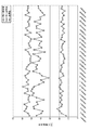
実験1〜3では、汚れ塗布前、汚れ塗布後、及び清掃後に、フェルールの端面の反射減衰量(dB)を50回測定した。 In Experiments 1 to 3, the reflection attenuation (dB) at the end face of the ferrule was measured 50 times before applying the stain, after applying the stain, and after cleaning.
実験1では、テープを回転させて、フェルールのフェルール端面を清掃した(図25(a)、図26参照)。 In Experiment 1, the tape was rotated to clean the ferrule end face of the ferrule (see FIGS. 25A and 26).
実験2では、テープを進行させて、フェルールのフェルール端面を清掃した(図25(b)、図27参照)。
In
実験3では、実施の形態と同様に、テープを進行させつつ回転して、フェルールのフェルール端面を清掃した(図25(c)、図28)。 In Experiment 3, as with the embodiment, the tape was rotated while being advanced to clean the ferrule end face of the ferrule (FIG. 25 (c), FIG. 28).
その結果、図25を参照して、実験1、実験2における清掃後の反射減衰量は、約40〜45dBの範囲にある。一方、実験3における清掃後の反射減衰量は約55dBであり、実験3の清掃効果は、実験1,2と比較して、向上した。従って、清掃テープを進行および回転させて清掃する本実施形態のクリーナは、清掃テープを単に進行または回転させて清掃するクリーナに比べて清掃効果の点で優れていることを示している。
As a result, referring to FIG. 25, the return loss after cleaning in Experiment 1 and
クリーナ1、1F、501は、光通信機器に組み込まれた光ファイバコネクタの接続面の清掃に用いられる。特に、光ファイバコネクタがアダプタに装着された場合、光ファイバコネクタのフェルールの接続面は、アダプタの奥に配置される。クリーナ1、1F、501はこのような奥まった接続面の清掃に適用可能である。
The
したがって、クリーナ1、1F、501は、光通信接続機器の出荷時のテストや、光通信接続機器に設置された光ファイバコネクタを何らかの理由で再接続する際のテストに好適である。
Therefore, the
1、1F クリーナ
10 ハウジング
20 清掃手段
21 清掃部
211 円筒
212 ローラ
22 ガイド
23、20F 清掃部回転手段
233 ピン
31 リール
32 巻き取り手段
32A ラチェット
33 リール
34 送り出し手段
34A ラチェエト
35 捻りばね
40 伝動手段
41 ハンドル
412 アーム
43 捻りばね
501 クリーナ
503 ハウジング
505、605 清掃部
507、607 内側ガイド部材
509、609 外側ガイド部材
511、611 ガイドスリーブ
513、613 第1のばね
515、615 第2のばね
525 清掃部回転手段
527 ピニオン
529 ラック
535 手動操作部
545 巻き取り手段
547 送り出し手段
549 巻き取りリール
551 胴部
553 第1の回転フランジ
554 第1のピニオン
555 第2の回転フランジ
556 第2のピニオン
559 第1のラチェット機構
561 第2のラチェット機構
571 第1のラック
573 第2のラック
575 可動フレーム
577 クランクロッド
591 カバー
T 清掃テープ
DESCRIPTION OF
Claims (27)
ハウジング(10)と、
前記ハウジング内部に配置された清掃テープの巻き取り手段(32)および送り出し手段(34)と、
前記ハウジングの外側に突出する棒状の清掃部(21)を有する清掃手段(20)であって、前記清掃部の先端に、前記送り出し手段から送り出された前記清掃テープが露出した状態でテープの長さ方向に移動可能に張架され、前記清掃部の先端を前記光ファイバコネクタの端面に接触させて前記端面を清掃する清掃手段と、
前記ハウジング内部において、前記清掃部に対して同軸に接続され、かつ前記ハウジングに対して回転自在に支承される清掃部回転手段(23)と、
前記巻き取り手段及び前記清掃部回転手段をほぼ同時にそれぞれ所定の方向に所定の角度回転させた後、前記清掃部回転手段を元の位置まで逆回転させる伝動手段(40)と、
を備える光ファイバコネクタ用クリーナ。 An optical fiber connector cleaner (1) comprising:
A housing (10);
A cleaning tape winding means (32) and a feeding means (34) disposed inside the housing;
A cleaning means (20) having a rod-like cleaning portion (21) protruding outside the housing, wherein the length of the tape is exposed while the cleaning tape fed from the feeding means is exposed at the tip of the cleaning portion. A cleaning means that is movably stretched in the vertical direction and that cleans the end face by bringing the tip of the cleaning portion into contact with the end face of the optical fiber connector;
In the housing, a cleaning unit rotating means (23) connected coaxially to the cleaning unit and rotatably supported with respect to the housing;
A transmission means (40) for rotating the winding section and the cleaning section rotating means substantially simultaneously in a predetermined direction at a predetermined angle, and then reversely rotating the cleaning section rotating means to the original position;
An optical fiber connector cleaner.
ハウジング(10)と、
前記ハウジング内部に装着された清掃テープ(T)の巻き取り手段(32)および送り出し手段(34)と、
前記ハウジングの外側に突出する棒状の清掃部(21)を有する清掃手段(20)であって、前記清掃部の先端に、前記送り出し手段から送り出された前記清掃テープが露出した状態でテープの長さ方向に移動可能に張架され、前記清掃部の先端を前記光ファイバコネクタの端面に接触させて前記端面を清掃する清掃手段と、
前記ハウジング内部において、前記清掃部に対して同軸に接続され、かつ前記ハウジングに対して回転自在に支承される清掃部回転手段(23)と、
前記清掃部に対して同軸に配置され、かつ前記ハウジングに支承される清掃テープのガイド手段(22)と、
前記巻き取り手段及び前記清掃部回転手段をほぼ同時にそれぞれ所定の方向に所定の角度回転させた後、前記清掃部回転手段を元の位置まで逆回転させる伝動手段(40)と、
を備える光ファイバコネクタ用クリーナ。 An optical fiber connector cleaner (1) comprising:
A housing (10);
A winding means (32) and a feeding means (34) of the cleaning tape (T) mounted inside the housing;
A cleaning means (20) having a rod-like cleaning portion (21) protruding outside the housing, wherein the length of the tape is exposed while the cleaning tape fed from the feeding means is exposed at the tip of the cleaning portion. A cleaning means that is movably stretched in the vertical direction and that cleans the end face by bringing the tip of the cleaning portion into contact with the end face of the optical fiber connector;
In the housing, a cleaning unit rotating means (23) connected coaxially to the cleaning unit and rotatably supported with respect to the housing;
Cleaning tape guide means (22) disposed coaxially with respect to the cleaning portion and supported by the housing;
A transmission means (40) for rotating the winding section and the cleaning section rotating means substantially simultaneously in a predetermined direction at a predetermined angle, and then reversely rotating the cleaning section rotating means to the original position;
An optical fiber connector cleaner.
クリーナのハウジング(10)内部の送り出し手段(34)から送り出され、且つ前記ハウジング内部の巻き取り手段(32)に巻き取られる清掃テープ(T)を、前記ハウジングから外側に突出する棒状の清掃部(21)の先端に、露出した状態でテープの長さ方向に移動可能に張架する工程と、
前記清掃部の先端の清掃テープを光ファイバコネクタのフェルール端面に接触させる工程と、
前記巻き取り手段及び前記清掃部を同時にそれぞれ所定の方向に所定の角度回転させることにより、前記清掃テープをその長手方向に一定の距離だけ移動させると同時に、前記清掃テープを前記光ファイバコネクタの接続面上で回転させる工程と、
前記回転させる工程の後に、前記清掃部を元の位置まで逆回転させる工程と、
を有する方法。 A method for cleaning a ferrule end face of an optical fiber connector using an optical fiber connector cleaner (1),
A cleaning tape (T) that is fed out from the feeding means (34) inside the cleaner housing (10) and is wound around the winding means (32) inside the housing, protrudes outward from the housing. (21) a step of stretching the tip in an exposed state so as to be movable in the length direction of the tape;
Contacting the cleaning tape at the tip of the cleaning part with the ferrule end surface of the optical fiber connector;
By simultaneously rotating the take-up means and the cleaning portion in a predetermined direction at a predetermined angle, the cleaning tape is moved by a predetermined distance in the longitudinal direction, and at the same time, the cleaning tape is connected to the optical fiber connector. Rotating on the surface,
After the step of rotating, the step of reversely rotating the cleaning unit to the original position;
Having a method.
クリーナのハウジング(10)内部の送り出し手段(34)から送り出され、且つ前記ハウジング内部の巻き取り手段(32)に巻き取られる清掃テープ(T)を、前記ハウジングから外側に突出する棒状の清掃部(21)の先端に、露出した状態でテープの長さ方向に移動可能に張架する工程と、
前記清掃部の先端を光ファイバコネクタに挿入する工程と、
前記清掃部の先端の清掃テープを前記光ファイバコネクタのフェルール端面に接触させる工程と、
前記清掃テープを前記フェルール端面に接触させている間に、前記巻き取り手段及び前記清掃部を同時にそれぞれ所定の方向に所定の角度回転させることにより、前記清掃テープを移動させると同時に回転させる工程と、
前記回転させる工程の後に、前記清掃部を元の位置まで逆回転させる工程と、
を有する方法。 A method for cleaning a ferrule end face of an optical fiber connector using an optical fiber connector cleaner (1),
A cleaning tape (T) that is fed out from the feeding means (34) inside the cleaner housing (10) and is wound around the winding means (32) inside the housing, protrudes outward from the housing. (21) a step of stretching the tip in an exposed state so as to be movable in the length direction of the tape;
Inserting the tip of the cleaning section into an optical fiber connector;
Contacting the cleaning tape at the tip of the cleaning part with the ferrule end surface of the optical fiber connector;
While the cleaning tape is in contact with the ferrule end face, simultaneously rotating and simultaneously rotating the cleaning tape by rotating the take-up means and the cleaning unit respectively at a predetermined angle in a predetermined direction; ,
After the step of rotating, the step of reversely rotating the cleaning unit to the original position;
Having a method.
ハウジング(503)と、
前記ハウジングの一端に設けられた清掃部(505、605)であって、棒状部材(507)を有し、前記棒状部材はその延伸軸を中心として回転可能に前記ハウジングに支持され、前記棒状部材の先端には、清掃テープ(T)が露出した状態でテープ長さ方向に移動可能に支持される清掃部と、
前記ハウジングに設けられた移動可能な操作部(535)と、
前記棒状部材および前記操作部に結合され、前記操作部の移動に応じて前記棒状部材を前記延伸軸を中心として回転させる清掃部回転駆動手段(525)と、
前記操作部に結合され、前記操作部の移動に応じて前記清掃テープを巻き取り、前記棒状部材の先端において前記清掃テープをテープの長さ方向に移動させる巻き取り手段(545)と、
を有し、
前記清掃部回転駆動手段が、前記操作部の第1の移動により、前記棒状部材を前記延伸軸回りの順方向に回転させ、前記操作部の第2の移動により、前記棒状部材を逆方向へ回転させて元の位置に戻し、
前記巻き取り手段が、前記ハウジングに回転可能に支持されて前記清掃テープを巻き取る巻き取り部(549)を有し、前記巻き取り部が、前記操作部の第1および第2の移動のどちらによっても、所定の回転方向へ回転して前記清掃テープを巻き取り、前記棒状部材の先端において前記清掃テープをテープの長さ方向に移動させる、光ファイバコネクタ用クリーナ。 An optical fiber connector cleaner (501) for cleaning an end face of a ferrule of an optical fiber connector,
A housing (503);
A cleaning portion (505, 605) provided at one end of the housing, which has a rod-shaped member (507), and the rod-shaped member is supported by the housing so as to be rotatable about its extending axis, and the rod-shaped member At the tip of the cleaning part, the cleaning part is supported so as to be movable in the tape length direction with the cleaning tape (T) exposed,
A movable operation part (535) provided in the housing;
A cleaning unit rotation driving means (525) coupled to the rod-shaped member and the operation unit and configured to rotate the rod-shaped member around the extending axis according to the movement of the operation unit;
Winding means (545) coupled to the operation section, winding the cleaning tape in accordance with movement of the operation section, and moving the cleaning tape in the length direction of the tape at the tip of the rod-shaped member;
Have
The cleaning unit rotation driving means rotates the rod-shaped member in the forward direction around the extending axis by the first movement of the operation unit, and reverses the rod-shaped member in the reverse direction by the second movement of the operation unit. Rotate it back to its original position,
The winding means has a winding portion (549) that is rotatably supported by the housing and winds the cleaning tape, and the winding portion is one of the first and second movements of the operation portion. Therefore, the cleaner for an optical fiber connector rotates in a predetermined rotation direction, winds up the cleaning tape, and moves the cleaning tape in the length direction of the tape at the tip of the rod-shaped member.
前記棒状部材(507)の基端に結合されたピニオン(527)と、
前記操作部(535)に設けられ、前記ピニオンと噛み合うラック(529)と、
を含む、請求項15に記載の光ファイバコネクタ用クリーナ。 The cleaning unit rotation driving means (525)
A pinion (527) coupled to the proximal end of the rod-shaped member (507);
A rack (529) provided in the operation portion (535) and meshing with the pinion;
The cleaner for optical fiber connectors of Claim 15 containing these.
前記ハウジング(503)に設けられた軸(557)に回転可能に支持されて前記清掃テープ(T)を巻き取る巻き取り部(551)と、
前記軸の延伸方向において前記巻き取り部の両側に配置され、前記軸に回転可能に支持される第1の回転駆動板(553)および第2の回転駆動板(555)と、
前記巻き取り部と第1回転駆動板の間に設けられた第1のラチェット機構(559)と、
前記巻き取り部と第2回転駆動板の間に設けられた第2のラチェット機構(561)と、
を有し、
前記第1および第2のラチェット機構は、前記軸を中心とする第1の回転方向の回転のみを前記巻き取り部に伝達する、請求項15に記載の光ファイバコネクタ用クリーナ。 The winding means (545)
A winding portion (551) that is rotatably supported by a shaft (557) provided in the housing (503) and winds the cleaning tape (T);
A first rotation drive plate (553) and a second rotation drive plate (555) disposed on both sides of the winding portion in the extending direction of the shaft and rotatably supported by the shaft;
A first ratchet mechanism (559) provided between the winding portion and the first rotation drive plate;
A second ratchet mechanism (561) provided between the winding portion and the second rotation drive plate;
Have
The optical fiber connector cleaner according to claim 15, wherein the first and second ratchet mechanisms transmit only rotation in a first rotation direction about the axis to the winding unit.
前記第1および第2のラックが、前記操作部の移動に応じて前記第1および第2の回転駆動板を互いに反対の方向に回転させるように、前記第1および第2のピニオンと噛み合う、請求項17に記載の光ファイバコネクタ用クリーナ。 The winding means (545) has a movable member (575) that moves in accordance with the movement of the operation portion (535), and the movable member is provided on the first rotary drive plate (553). A first rack (571) that meshes with the first pinion (554), a second rack (573) that meshes with the second pinion (556) provided on the second rotation drive plate (555), Have
The first and second racks mesh with the first and second pinions so as to rotate the first and second rotary drive plates in opposite directions according to the movement of the operation unit; The cleaner for optical fiber connectors of Claim 17.
前記ハウジング(503)に支持された筒状のガイドスリーブ(511)と、
前記ガイドスリーブの内側面に前記延伸軸に沿って摺動可能に支持され、前記棒状部材(507)と清掃テープ(T)を前記延伸軸に沿って摺動可能に収容する筒状の外側ガイド部材(509)と、
を有し、
前記棒状部材が、前記清掃部回転駆動手段(525)からの回転力を受けるように、連結部材(513)を介して前記清掃部回転駆動手段に連結され、
前記外側ガイド部材が、前記ガイドスリーブに形成された段部(511a)と係合可能な係合部(509c)を有し、前記段部と係合部とが係合するように、前記外側ガイド部材と前記棒状部材の間に設けたばね(515)により、前記延伸軸に沿って前記棒状部材の先端方向に付勢される、請求項15に記載の光ファイバコネクタ用クリーナ。 The cleaning unit (505)
A cylindrical guide sleeve (511) supported by the housing (503);
A cylindrical outer guide supported on the inner surface of the guide sleeve so as to be slidable along the extending axis, and accommodating the rod-like member (507) and the cleaning tape (T) slidably along the extending axis. A member (509);
Have
The rod-shaped member is connected to the cleaning unit rotation driving means via a connecting member (513) so as to receive the rotational force from the cleaning unit rotation driving means (525),
The outer guide member has an engaging portion (509c) engageable with a step portion (511a) formed on the guide sleeve, and the outer guide member engages with the outer portion so that the step portion and the engaging portion engage with each other. The optical fiber connector cleaner according to claim 15, wherein the cleaner is biased in the distal direction of the rod-shaped member along the extending axis by a spring (515) provided between the guide member and the rod-shaped member.
前記ハウジング(503)に支持された筒状のガイドスリーブ(611)と、
前記ガイドスリーブの内側面に前記延伸軸に沿って摺動可能に支持され、前記棒状部材(607)と清掃テープ(T)を前記延伸軸に沿って摺動可能に収容する筒状の外側ガイド部材(609)と、
前記延伸軸を中心として回転可能に前記ガイドスリーブの基部に支持されたロータリージョイント(619)であって、前記棒状部材の基端と前記延伸軸に対する周方向において互いに不動に且つ前記延伸軸に沿って摺動可能に係合するロータリージョイントと、
を有し、
前記ロータリージョイントが、前記清掃部回転駆動手段(525)からの回転力を受けるように、連結部材(613)を介して前記清掃部回転駆動手段に連結され、
前記棒状部材が、前記ガイドスリーブに設けられた係合部(621a)と係合可能な棒状部材フランジ(607c)を有し、前記棒状部材フランジが前記係合部と係合するように、前記棒状部材フランジと前記ロータリージョイントの間に設けられたばね(617)により、前記延伸軸に沿って前記棒状部材の先端方向に付勢され、
前記外側ガイド部材が、前記ガイドスリーブに形成された段部(611a)と係合可能な外側ガイド部材フランジ(609c)を有し、前記外側ガイド部材フランジが前記段部と係合するように、前記外側ガイド部材フランジと前記ガイドスリーブの係合部の間に設けられたばね(615)により、前記延伸軸に沿って前記棒状部材の先端方向に付勢される、請求項15に記載の光ファイバコネクタ用クリーナ。 The cleaning unit (605)
A cylindrical guide sleeve (611) supported by the housing (503);
A cylindrical outer guide that is supported on the inner surface of the guide sleeve so as to be slidable along the extending axis, and that accommodates the rod-shaped member (607) and the cleaning tape (T) slidably along the extending axis. A member (609);
A rotary joint (619) supported by a base portion of the guide sleeve so as to be rotatable about the stretching axis, the base end of the rod-shaped member and the circumferential direction with respect to the stretching axis being fixed to each other and along the stretching axis A rotary joint that slidably engages,
Have
The rotary joint is connected to the cleaning part rotation driving means via a connecting member (613) so as to receive a rotational force from the cleaning part rotation driving means (525),
The rod-shaped member has a rod-shaped member flange (607c) that can be engaged with an engaging portion (621a) provided on the guide sleeve, and the rod-shaped member flange is engaged with the engaging portion. The spring (617) provided between the rod-shaped member flange and the rotary joint is biased in the distal direction of the rod-shaped member along the extending axis,
The outer guide member has an outer guide member flange (609c) that can be engaged with a step (611a) formed on the guide sleeve, and the outer guide member flange is engaged with the step. The optical fiber according to claim 15, wherein the optical fiber is urged toward the distal end of the rod-shaped member along the extending axis by a spring (615) provided between the outer guide member flange and the engaging portion of the guide sleeve. Connector cleaner.
前記巻き取り手段(545)が、前記操作部に機械的に結合される、請求項15に記載の光ファイバコネクタ用クリーナ。 The cleaning unit rotation driving means (525) is mechanically coupled to the rod-shaped member (607) and the operation unit (535),
The optical fiber connector cleaner according to claim 15, wherein the winding means (545) is mechanically coupled to the operating portion.
Priority Applications (1)
| Application Number | Priority Date | Filing Date | Title |
|---|---|---|---|
| JP2004196711A JP4011564B2 (en) | 2003-08-13 | 2004-07-02 | Optical fiber connector cleaner and optical fiber connector connection surface cleaning method |
Applications Claiming Priority (3)
| Application Number | Priority Date | Filing Date | Title |
|---|---|---|---|
| JP2003293006 | 2003-08-13 | ||
| JP2003400172 | 2003-11-28 | ||
| JP2004196711A JP4011564B2 (en) | 2003-08-13 | 2004-07-02 | Optical fiber connector cleaner and optical fiber connector connection surface cleaning method |
Publications (3)
| Publication Number | Publication Date |
|---|---|
| JP2005181971A JP2005181971A (en) | 2005-07-07 |
| JP2005181971A5 JP2005181971A5 (en) | 2007-05-17 |
| JP4011564B2 true JP4011564B2 (en) | 2007-11-21 |
Family
ID=34799274
Family Applications (1)
| Application Number | Title | Priority Date | Filing Date |
|---|---|---|---|
| JP2004196711A Active JP4011564B2 (en) | 2003-08-13 | 2004-07-02 | Optical fiber connector cleaner and optical fiber connector connection surface cleaning method |
Country Status (1)
| Country | Link |
|---|---|
| JP (1) | JP4011564B2 (en) |
Families Citing this family (14)
| Publication number | Priority date | Publication date | Assignee | Title |
|---|---|---|---|---|
| EP2641667B1 (en) * | 2007-02-28 | 2014-12-24 | Fujikura Ltd. | Optical connector cleaning tool |
| JP5178626B2 (en) * | 2009-05-14 | 2013-04-10 | 株式会社フジクラ | Optical connector cleaning tool |
| JP5466899B2 (en) * | 2009-07-30 | 2014-04-09 | 株式会社フジクラ | Optical connector cleaning tool |
| JP5264666B2 (en) * | 2009-09-29 | 2013-08-14 | 株式会社フジクラ | Optical connector cleaning tool |
| JP5364604B2 (en) * | 2010-01-20 | 2013-12-11 | 株式会社フジクラ | Optical connector cleaning tool |
| JP5111576B2 (en) * | 2010-08-27 | 2013-01-09 | 株式会社フジクラ | Optical connector cleaning tool |
| JP5111577B2 (en) * | 2010-08-27 | 2013-01-09 | 株式会社フジクラ | Optical connector cleaning tool |
| JP2012063506A (en) * | 2010-09-15 | 2012-03-29 | Fujikura Ltd | Optical connector cleaning tool |
| JP5525628B2 (en) * | 2012-01-19 | 2014-06-18 | エヌ・ティ・ティ・アドバンステクノロジ株式会社 | Optical connector cleaning tool |
| WO2019176404A1 (en) | 2018-03-12 | 2019-09-19 | 株式会社巴川製紙所 | Optical connector end surface cleaner |
| JP6889333B2 (en) * | 2019-02-20 | 2021-06-18 | エヌ・ティ・ティ・アドバンステクノロジ株式会社 | Cleaning tool for optical connector |
| JPWO2021029388A1 (en) * | 2019-08-14 | 2021-02-18 | ||
| WO2022074861A1 (en) * | 2020-10-07 | 2022-04-14 | 株式会社フジクラ | Cleaning tool and cleaning method |
| WO2022269991A1 (en) * | 2021-06-23 | 2022-12-29 | 株式会社フジクラ | Optical connector cleaning tool |
-
2004
- 2004-07-02 JP JP2004196711A patent/JP4011564B2/en active Active
Also Published As
| Publication number | Publication date |
|---|---|
| JP2005181971A (en) | 2005-07-07 |
Similar Documents
| Publication | Publication Date | Title |
|---|---|---|
| KR100770377B1 (en) | Optical fiber connector cleaner, and method of cleaning optical fiber connector connection surface | |
| JP4011564B2 (en) | Optical fiber connector cleaner and optical fiber connector connection surface cleaning method | |
| US8266755B2 (en) | Cleaning device of optical connector | |
| JP3927212B2 (en) | Fiber optic connector cleaner | |
| EP0391111B1 (en) | Optical connector cleaner | |
| JP4779049B2 (en) | Optical connector cleaning tool | |
| EP2746829B1 (en) | Optical connector cleaning tool and optical connector cleaning method | |
| US5220703A (en) | Combination of optical connector cleaner and holder jig | |
| US8397337B2 (en) | Optical connector cleaning tool | |
| JP5596878B1 (en) | Fiber optic connector cleaning cleaner | |
| US20110154599A1 (en) | Cleaning device of optical connector | |
| TW201516506A (en) | Device for cleaning optical fiber connector | |
| US6619857B2 (en) | Cleaning tool for optical connector | |
| US11226454B2 (en) | Cleaning tool for optical connector | |
| JP2004233378A (en) | Cleaning unit for optical connector and cleaning tool for optical connector | |
| CN100442094C (en) | Cleaner for optical fiber connector and method for cleaning connection surface of optical fiber connector | |
| JP4350683B2 (en) | Optical connector cleaning tool and optical component cleaning tool | |
| JP7406649B2 (en) | Cleaning tools and cleaning methods | |
| US20240027692A1 (en) | Optical connector cleaning tool | |
| WO2023233702A1 (en) | Optical connector cleaning tool | |
| WO2022269991A1 (en) | Optical connector cleaning tool | |
| JP2539020B2 (en) | Optical connector cleaning equipment | |
| WO2023234180A1 (en) | Cleaning tool | |
| JP2019168510A (en) | Optical connector cleaning tool | |
| JP2010186041A (en) | Connection device for optical connector |
Legal Events
| Date | Code | Title | Description |
|---|---|---|---|
| A521 | Written amendment |
Free format text: JAPANESE INTERMEDIATE CODE: A523 Effective date: 20070327 |
|
| A621 | Written request for application examination |
Free format text: JAPANESE INTERMEDIATE CODE: A621 Effective date: 20070327 |
|
| A871 | Explanation of circumstances concerning accelerated examination |
Free format text: JAPANESE INTERMEDIATE CODE: A871 Effective date: 20070327 |
|
| A975 | Report on accelerated examination |
Free format text: JAPANESE INTERMEDIATE CODE: A971005 Effective date: 20070416 |
|
| A131 | Notification of reasons for refusal |
Free format text: JAPANESE INTERMEDIATE CODE: A131 Effective date: 20070508 |
|
| A521 | Written amendment |
Free format text: JAPANESE INTERMEDIATE CODE: A523 Effective date: 20070612 |
|
| A131 | Notification of reasons for refusal |
Free format text: JAPANESE INTERMEDIATE CODE: A131 Effective date: 20070710 |
|
| A521 | Written amendment |
Free format text: JAPANESE INTERMEDIATE CODE: A523 Effective date: 20070727 |
|
| TRDD | Decision of grant or rejection written | ||
| A01 | Written decision to grant a patent or to grant a registration (utility model) |
Free format text: JAPANESE INTERMEDIATE CODE: A01 Effective date: 20070828 |
|
| A61 | First payment of annual fees (during grant procedure) |
Free format text: JAPANESE INTERMEDIATE CODE: A61 Effective date: 20070905 |
|
| R150 | Certificate of patent or registration of utility model |
Ref document number: 4011564 Country of ref document: JP Free format text: JAPANESE INTERMEDIATE CODE: R150 Free format text: JAPANESE INTERMEDIATE CODE: R150 |
|
| FPAY | Renewal fee payment (event date is renewal date of database) |
Free format text: PAYMENT UNTIL: 20100914 Year of fee payment: 3 |
|
| FPAY | Renewal fee payment (event date is renewal date of database) |
Free format text: PAYMENT UNTIL: 20100914 Year of fee payment: 3 |
|
| FPAY | Renewal fee payment (event date is renewal date of database) |
Free format text: PAYMENT UNTIL: 20110914 Year of fee payment: 4 |
|
| R250 | Receipt of annual fees |
Free format text: JAPANESE INTERMEDIATE CODE: R250 |
|
| FPAY | Renewal fee payment (event date is renewal date of database) |
Free format text: PAYMENT UNTIL: 20120914 Year of fee payment: 5 |
|
| R250 | Receipt of annual fees |
Free format text: JAPANESE INTERMEDIATE CODE: R250 |
|
| FPAY | Renewal fee payment (event date is renewal date of database) |
Free format text: PAYMENT UNTIL: 20130914 Year of fee payment: 6 |
|
| R250 | Receipt of annual fees |
Free format text: JAPANESE INTERMEDIATE CODE: R250 |
|
| R250 | Receipt of annual fees |
Free format text: JAPANESE INTERMEDIATE CODE: R250 |
|
| R250 | Receipt of annual fees |
Free format text: JAPANESE INTERMEDIATE CODE: R250 |
|
| R250 | Receipt of annual fees |
Free format text: JAPANESE INTERMEDIATE CODE: R250 |
|
| R250 | Receipt of annual fees |
Free format text: JAPANESE INTERMEDIATE CODE: R250 |
|
| R250 | Receipt of annual fees |
Free format text: JAPANESE INTERMEDIATE CODE: R250 |
|
| R250 | Receipt of annual fees |
Free format text: JAPANESE INTERMEDIATE CODE: R250 |
|
| R250 | Receipt of annual fees |
Free format text: JAPANESE INTERMEDIATE CODE: R250 |
|
| R250 | Receipt of annual fees |
Free format text: JAPANESE INTERMEDIATE CODE: R250 |
|
| R250 | Receipt of annual fees |
Free format text: JAPANESE INTERMEDIATE CODE: R250 |
|
| R250 | Receipt of annual fees |
Free format text: JAPANESE INTERMEDIATE CODE: R250 |