JP4011291B2 - Drawer detection device - Google Patents
Drawer detection device Download PDFInfo
- Publication number
- JP4011291B2 JP4011291B2 JP2001006461A JP2001006461A JP4011291B2 JP 4011291 B2 JP4011291 B2 JP 4011291B2 JP 2001006461 A JP2001006461 A JP 2001006461A JP 2001006461 A JP2001006461 A JP 2001006461A JP 4011291 B2 JP4011291 B2 JP 4011291B2
- Authority
- JP
- Japan
- Prior art keywords
- drawer
- lever
- detection
- storage unit
- main body
- Prior art date
- Legal status (The legal status is an assumption and is not a legal conclusion. Google has not performed a legal analysis and makes no representation as to the accuracy of the status listed.)
- Expired - Fee Related
Links
Images


Description
【0001】
【発明の属する技術分野】
この発明は、例えば金融機関に設置されるATM(自動預金支払機)や自動券売機などの取引処理装置に装填される媒体収納装置に備えられるような引出し検知装置に関し、さらに詳しくは引出された収納部の引出し履歴情報を確保して収納された媒体の管理性能を高めることができる引出し検知装置に関する。
【0002】
【従来の技術】
以下、現金を内部に収納管理するATMを例にとって説明する。
【0003】
通常、ATMの内部には現金を出入れ処理するための紙幣処理装置や硬貨処理装置を搭載しており、これらの収納した現金の管理に際しては、装置本体より現金収納部が引出される毎に、その引出し位置を検知スイッチ、検知センサが検知することに基づいて引出し情報を取得し、この引出し情報をログ・ジャーナル等に記録して引出し履歴情報を管理している。
【0004】
この引出し履歴情報を確保することにより、現金違算が発生したときの解析に役立てている。例えば、ATMの収納部に現金違算が発生して違算発生原因を解析するとき、現金収納部が係員により引出された人為的なことによるものか、ATM処理不良による機械的なことによるものなのかの判断基準により、違算発生原因を明確に追及して解析することができる。
【0005】
【発明が解決しようとする課題】
しかし、このような違算発生原因の解析は、電源が入っているときに引出し履歴情報が記録されて証拠として確実に入手できるが、電断中の場合は引出し履歴情報がログやジャーナルに記録されないため不明であり、違算発生原因が人手による可能性があるものか、機械動作の処理不良によるものなのかを特定できず、電断があった場合は違算発生原因を解析できなかった。
【0006】
そこでこの発明は、電断中に収納部が引出し動作されても該収納部の引出し履歴情報を確実に取得して、収納部の引出し動作を管理できるため、信頼性の高い媒体収納管理性能が得られる引出し検知装置の提供を目的とする。
【0007】
【課題を解決するための手段】
媒体を収納する収納部が装置本体から引出されたことを検知する引出し検知装置であって、前記収納部は、前記収納部が装置本体から引出された引出し動作に連動して、引出し検知位置に移動する可動手段と、前記可動手段を移動後の前記引出し検知位置で係止する係止手段と、前記収納部の前記可動手段が引出し検知位置に係止されていることを、前記装置本体の電源の投入に連動して検知する検知手段と、前記検知手段の検知動作に連動して、それまでの電断中の前記収納部の引出し動作の有無を、前記検知手段の検知結果に基づいて判定する判定手段とを備えたことを特徴とする。
【0008】
ここで、媒体とは収納部に収納される紙幣、硬貨、券、カードなどである。
【0009】
前記収納部とは、媒体を内部に収納する収納空間を有して、装置本体に着脱利用されるカートリッジやカセットの単体、あるいはこれらの収納群を搭載して一括して引出し利用される処理部などである。
【0010】
前記可動手段とは、収納部の引出し動作に連動して動く可動レバーで構成することができる。
【0011】
前記検知手段とは、収納部の引出し動作に応じて移動する可動レバーの動きを検知する検知センサで構成することができる。
【0012】
前記判定手段とは、CPUで構成することができ、また通知手段を備えて装置本体の制御部に通知することができる。
【0013】
この結果、装置本体に電源が入っていなくても、該装置本体より収納部が引出されると、この引出し動作に連動して可動手段が移動し、この移動したことを検知手段が検知することにより、判定手段は収納部の引出し動作の有無を判定することができる。
【0014】
したがって、電源が入っていても、入っていなくても収納部の引出しの有無を確実に確認できるため、違算が発生したときは、その原因が人手による可能性があるものか、機械の処理不良によるものなのかを特定できる。また、電断中の収納部引出し確認用にバッテリを備えて管理するなどの電気的な手法に頼らず、機械的な検知手段を部分的に付加するだけで引出し履歴情報を的確に管理できるため低コスト化が図れる。
【0015】
このような管理下にあるため、収納部は不必要に引出されることがなくなり、また係員の誤操作による障害発生の低減化が図れる。さらに、現金収納部に適用した場合は、現金管理能力が向上し、信頼性の高い運用管理が図れる。このため、セキュリティ会社などの第三者に委託する場合にも、セキュリティが高い管理下のもとで安心して委託できる。
【0016】
【発明の実施の形態】
この発明の一実施の形態を以下図面に基づいて詳述する。
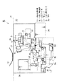
図面はATMに内蔵される現金処理装置を示し、図1において、この現金処理装置11は装置本体12の内部に長方体状を有して一側面より出入れ自由に内蔵されており、この現金処理装置11の内部に、さらに現金収納部13と現金装填部14を内蔵して構成している。
【0017】
上述の現金処理装置11の引出しに際しては、引出し方向に沿って配設されたスライドレールやスライドガイド板などのスライド部材15にガイドされて装置本体12より引出される。この場合、引出されたことを検知する電気的な引出し検知手段に加えて、機械的な引出し検知装置16を付加している。
【0018】
上述の引出し検知装置16は、装置本体12に固定された固定ガイド板17に対し、現金処理装置11の側面に小さく開口する開口窓18を介して内部から外部に向けて突出させた引出し検知用の第1レバーL1 を引出し方向に対向させて設けることにより、後述する現金処理装置11の引出し検知動作を行わせる。
【0019】
図2は固定ガイド板17と対向して現金処理装置11に内部構成される引出し検知装置16を示し、この引出し検知装置16は上述した引出し検知用の第1レバーL1 と、ロック用の第2レバーL2 と、ロック用の第3レバーL3 と、引出し検知センサSとを組合せて構成される。
【0020】
上述の第1レバーL1 はL形状を有し、そのレバーの屈曲位置を第1回動軸19で軸支して基板20上に回動自由に取付けている。さらに、この第1レバーL1 のL形内端位置には第1付勢バネ21を取付けている。この第1付勢バネ21は基板20上の第1起立片22に一端を接続し、この第1起立片22側を引張り基準位置として同バネ21の他端を第1レバーL1 のL形内端位置に接続することにより該レバーL1 を図中左回り方向に回動付勢して設け、該レバーL1 の内端部の係止対応片23aが固定ストッパ片23に当接した状態で保持され、この保持状態で該レバーL1 の外端部に位置する突片24が上述した開口窓18を介して外方に臨ませた突出状態にある。
【0021】
また、この突片24と回動対応する内方位置には引出し検知センサSを配設しており、突片24が外方に突出した状態では引出し検知センサSは突片24によって検知位置が遮光されないON(引出されていない待機)状態にある。
【0022】
これに対し、図2の想像線および図3に示すように、第1付勢バネ21の付勢力に抗して第1レバーL1 が第1回動軸19を支点に回動し、突片24が内方の現金処理装置11に没入すると、この突片24が引出し検知センサSの検知位置を遮光するためOFF(引出された検知)状態になる。
【0023】
このときの引出し検知センサSのON・OFF動作は、現金処理装置11が装置本体12より引出されたときに、図3に示すように、逆へ字形状の固定ガイド板17に第1レバーL1 の外方に突出する突片24が引出し過程で滑らかに接触して次第に押し戻されて没入動作することにより、該レバーL1 が回動し、これに基づいて引出し検知センサSは引出し検知信号(OFF信号)を出力して現金処理装置11が装置本体12より引出されたことを検知する。
【0024】
次に、第2レバーL2 について説明する。
この第2レバーL2 は細長い長尺状を有し、その中間位置を第2回動軸25で回動自由に軸支して基板20上に取付けている。さらに、この第2レバーL2 の一端部(図中左端)には、該レバーL2 を挟む相反する方向からレバーロック解除用の上部ソレノイド26と第2付勢バネ27とを接続している。
【0025】
上述の第2付勢バネ27は基板20上の第2起立片28に一端を接続し、この起立片28側を引張り基準位置として同バネ27の他端を第2レバーL2 に接続することにより該レバーL2 を図中左回転方向に回動付勢して設け、該レバーL2 の他端側の先端係止部29が既述した固定ストッパ片23に共通して位置規制された当接状態で保持され、また上述したレバーL1 の係止対応片23aと対応して第1レバーL1 が没入したときの回動位置で第1レバーL1 を係止する。
【0026】
この保持状態で該レバーの一端に接続された上部ソレノイド26を駆動すると、第2付勢バネ27の付勢力に抗して第2レバーL2 は少し回動し、該レバーL2 の先端係止部29が後述する第3レバーの係合部に係合して第3レバーをロックする。
【0027】
次に、第3レバーL3 について説明する。
上述の第3レバーL3 は凹形状を有し、そのレバー下部位置を第3回動軸30で回動自由に軸支して基板20上に取付けている。さらに、この第3レバーL3 の一側(図中右端)には、該レバーL3 を挟む相反する方向からロック解除用の下部ソレノイド31と第3付勢バネ32とを接続している。
【0028】
上述の第3付勢バネ32は基板20上の共通する第2起立片28に一端を接続し、この起立片28側を引張り基準位置として同バネ32の他端を第3レバーL3 に接続することにより該レバーL3 を図中左回転方向に回動付勢して設け、該レバーL3 の一端の係止段部33aが基板20上の第3起立片33に位置規制された当接状態で保持されている。
【0029】
この保持状態で該レバーの一端に接続された下部ソレノイド31を駆動すると、第3付勢バネ32の付勢力に抗して第3レバーL3 は少し回動し、該レバーL3 の下部に切欠き形成した逆凹形係止部34が現金装填装置14のロック部材35と外れて現金装填装置14をロック解除し、現金処理装置11内に収納されている現金装填装置14の取出しが可能になる。
【0030】
また、第3レバーL3 の一端部には、上述した第2レバーL2 の先端係止部29と係止対応可能な係止片29aを有しており、上部ソレノイド26のON動作に基づいて係止対応して第3レバーL3 がロックされる。
【0031】
図4は引出し検知装置16の制御回路ブロック図を示し、CPU41はROM42に格納されたプログラムに沿って各回路装置を制御し、その制御データをRAM43で読出し可能に記憶する。
【0032】
通信装置44は、現金処理装置11が引出されたことを引出し検知センサSが検知したとき、この検知情報を検知時刻の情報も含めて上位の制御部に送信する。またCPU41は、ATMの起動時に、それまでの電断中に現金処理装置11の引出し動作有りと判定したときにも、その引出し有りの情報を上位の制御部に通知する。
【0033】
このように構成された引出し検知装置16は、通常、現金処理装置11が装置本体12内にセットされた状態では、図1および図2に示すように、開口窓18より第1レバーL1 の突片24が突出した状態にあり、該突片24の内方にあっては引出し検知センサSが突片24を検知せず、現金処理装置11が引出されていないことを確認している。
【0034】
次に、この現金処理装置11が装置本体12より引出し動作されたときは、図3に示すように、第1レバーL1 と一体の突片24が引出し過程で傾斜対向面を有する固定ガイド板17に次第に加圧接触して突片24が没入動作することにより該レバーL1 が回動し、これに基づいて引出し検知センサSは突片24の存在を検知して引出し検知信号を制御部に出力し、現金処理装置11が装置本体12より引出されたことを検知する。
【0035】
したがって、装置本体12に電源が入っていない運用停止状態で現金処理装置11が係員により引出し操作された場合は、引出し検知装置16が機械的に検知すべく、引出し動作に連動して突片24が引出し検知センサSの位置を遮光することになり、この状態で起動するため、ATMの起動時点で引出しの有無情報を入手することができる。
【0036】
このため、電源が入っていても、入っていなくても現金処理装置11の引出し有無を確実に管理できる。このため、違算が発生したときは、その原因が人手によるものか、機械の処理不良によるものなのかを特定することができる。
【0037】
この現金処理装置11を元の収納セット位置に戻したときには、同じく第1レバーL1 の突片24の位置も上部ソレノイド26を駆動して初期設定位置に戻す。この復帰動作は、上部ソレノイド26の駆動に基づいて、第1レバーL1 が第2レバーL2 による位置規制が解かれて元の復帰位置に戻る。
【0038】
また、現金装填部14の取出しに際しては、第3レバーL3 を係員が手で持上げるか、下部ソレノイド31を駆動すると、第3レバーL3 が傾動して現金処理装置11の内部に装填されている現金装填装置14のロック部材35との係合が外れてロック解除され、現金装填部14の取出しが可能になる。
【0039】
また、ATMが稼動状態などで現金装填部14が動作中のときは該現金装填部14の取出し不可のため、上部ソレノイド26を駆動して第2レバーL2 の先端係止部29を第3レバーL3 の係止片29aに係合ロックさせて、第3レバーL3 を持上げ規制したロック状態を確保して安全性を保っている。
【0040】
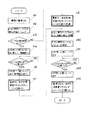
次に、引出し検知装置16の処理動作を図5のフローチャートを参照して説明する。
今、ATMの電源を入れた時、CPU41は引出し検知センサSが引出し検知しているか、否かを判定し(ステップn1 〜n2 )、
引出し検知していると判定したときは、第1レバーL1 を元の位置に戻すべく上部ソレノイド26を駆動し、これに基づいて第1レバーL1 の突片24が初期位置に復帰して引出し検知センサSが引出し検知しない元の位置に戻る(ステップn3 〜n6 )。
【0041】
このときは、電断中に現金処理装置11の引出し操作が係員により行われたと判定して、その旨を記録して次の引出し動作に備える(ステップn 7 )。また、上部ソレノイド26を駆動しても引出し未検知信号が得られなければ、エラー発生を出力する(ステップn 5 )。
【0042】
ATMの電源を入れた時に、引出し検知センサSが引出し検知信号を未検知の初期設定のままの場合は、電断中に現金処理装置11の引出し操作がなかったことを表し、この場合は記録せずに、次の引出し動作に備える(ステップn8 )。
【0043】
次に、電源ON中に現金処理装置11の引出し操作が行われたときは、その旨を引出し検知装置16が検出し、現金処理装置11が再び係員により元の位置に戻されて再セットされると、既述したステップn4 〜n6 と同様に、上部ソレノイド26を駆動して第1レバーL1 の突片24を初期設定位置に戻す(ステップn9 〜n13)。
【0044】
この引出し時にも、電源ON中に現金処理装置11の引出し動作が行われたことを時刻と共に記録する(ステップn14)。
【0045】
上述のように、装置本体に電源が入っていなくても、該装置本体より現金処理装置が引出されると、この引出し動作に連動して第1レバーが移動し、この移動したことを引出し検知センサが検知することにより、CPUは現金処理装置の引出し動作の有無を判定することができる。したがって、電源が入っていても、入っていなくても現金処理装置の引出しの有無を確実に確認できるため、違算が発生したときは、その原因が人手によるものか、機械の処理不良によるものなのかを特定することができる。また、バッテリを備えて管理するなどの電気的な手法に頼らないため低コスト化が図れ、機械的な検知手段を付加するだけで引出し履歴情報を的確に管理することができる。
【0046】
このような管理下にあるため、現金処理装置は不必要に引出されることがなくなり、また係員の誤操作による障害発生の低減化が図れる。さらに、ATMなどの現金を取扱う収納部に適用した場合は、現金管理能力が向上し、信頼性の高い運用管理が図れる。このため、セキュリティ会社などの第三者に委託する場合にもセキュリティが高い管理下のもとで安心して委託できる。
【0047】
この発明の構成と、上述の一実施の形態との対応において、
この発明の収納部は、実施の形態の現金処理装置11に対応し、
以下同様に、
媒体は、現金に対応し、
可動手段および可動レバーは、第1レバーL1 の突片24に対応し、
係止手段およびロック手段は、第2レバーL2に対応し、
検知手段および検知センサは、引出し検知センサSに対応し、
ロック解除手段は、上部ソレノイド26に対応し、
判定手段は、CPU41に対応し、
通知手段は、通信装置44に対応するも、
この発明は、請求項に示される技術思想に基づいて応用することができ、上述の一実施の形態の構成のみに限定されるものではない。
【0048】
例えば、固定ガイド板17の取付け位置は装置本体12に限らず、現金装填装置14に現金収納部13も全て入っている場合、固定ガイド板17は装置本体12側に固定するのではなく、現金処理装置11に固定してもよい。
【0049】
【発明の効果】
この発明によれば、電源が入っていても、入っていなくても収納部の引出し有無を確実に管理できるため、違算が発生したときは、その原因が人手によるものか、機械の処理不良によるものなのかを特定できる。また、バッテリを備えて管理するなどの電気的な手法に頼らないため低コスト化が図れ、機械的な検知手段を付加するだけで引出し履歴情報を的確に管理することができる。
【図面の簡単な説明】
【図1】 現金処理装置に適用した引出し検知装置の外観斜視図。
【図2】 引出し検知装置の引出し前の状態を示す内部構成図。
【図3】 引出し検知装置の引出し後の状態を示す内部構成図。
【図4】 引出し検知装置の制御回路ブロック図。
【図5】 引出し検知装置の処理動作を示すフローチャート。
【符号の説明】
11…現金処理装置
12…装置本体
16…引出し検知装置
17…固定ガイド板
L1 …第1レバー
S…引出し検知センサ
24…突 片
41…CPU
44…通信装置[0001]
BACKGROUND OF THE INVENTION
The present invention relates to a drawer detection apparatus provided in a medium storage device loaded in a transaction processing apparatus such as an ATM (automatic deposit payment machine) or an automatic ticket vending machine installed in a financial institution, for example. The present invention relates to a drawer detection apparatus capable of securing the drawer history information of a storage unit and improving the management performance of a stored medium.
[0002]
[Prior art]
Hereinafter, an explanation will be given by taking an ATM that stores and manages cash as an example.
[0003]
Usually, the ATM is equipped with a banknote processing device and a coin processing device for processing cash in and out, and each time the cash storage unit is withdrawn from the device main body when managing the stored cash. The drawer information is acquired based on the detection switch and the detection sensor detecting the drawer position, and the drawer history information is managed by recording the drawer information in a log / journal.
[0004]
By securing this withdrawal history information, it is useful for analysis when a cash miscalculation occurs. For example, when cash miscalculation occurs in the ATM storage department and the cause of the miscalculation is analyzed, is it due to the cash storage department being artificially drawn by a clerk or mechanical due to ATM processing failure? Therefore, the cause of the miscalculation can be clearly pursued and analyzed.
[0005]
[Problems to be solved by the invention]
However, such an analysis of the cause of miscalculation can be reliably obtained as evidence that the withdrawal history information is recorded when the power is on, but the withdrawal history information is not recorded in the log or journal when power is interrupted. Therefore, it was unclear, and it was not possible to determine whether the cause of the miscalculation was due to manual processing or due to poor processing of the machine operation. If there was a power failure, the cause of the miscalculation could not be analyzed.
[0006]
Therefore, the present invention can reliably acquire the drawer history information of the storage unit even if the storage unit is pulled out during power interruption, and can manage the drawer operation of the storage unit. An object of the present invention is to provide a drawer detection device.
[0007]
[Means for Solving the Problems]
A drawer detection device for detecting that a storage unit for storing a medium is pulled out from the apparatus main body, wherein the storage unit is moved to a drawer detection position in conjunction with a drawing operation in which the storage unit is pulled out from the apparatus main body. and availability motion means for moving the locking means for locking in the extraction detection position after moving said movable means, said friendly motion means of the housing part is locked to the drawer detection position, said device The detection means for detecting in conjunction with the power-on of the main body, and the detection result of the detection means for the presence or absence of the pulling-out operation of the storage unit during power interruption in conjunction with the detection operation of the detection means. And a determination means for determining based on the determination means.
[0008]
Here, the medium is a bill, a coin, a ticket, a card or the like stored in the storage unit.
[0009]
The storage unit has a storage space for storing a medium therein, and is a processing unit that is used as a single unit of cartridges and cassettes that are detachably used in the apparatus main body or a group of these storage units that are pulled out and used together. Etc.
[0010]
The said allowed movement means can be constituted by a movable lever that moves in conjunction with the pull-out operation of the storage unit.
[0011]
The detection means can be constituted by a detection sensor that detects the movement of a movable lever that moves in accordance with the drawing operation of the storage section.
[0012]
The determination means can be constituted by a CPU, and can be provided with a notification means to notify the control section of the apparatus main body.
[0013]
As a result, even if no powered the apparatus main body, the accommodating portion from the apparatus main body is pulled out, in conjunction with the drawer operation moves allowed motion means, for detecting the detection means that this movement Thereby, the determination means can determine the presence or absence of the drawer | drawing-out operation | movement of a storage part.
[0014]
Therefore, it is possible to confirm whether or not the storage unit has been pulled out, whether it is turned on or not. Can be identified. In addition, it is possible to accurately manage the drawer history information by adding only a mechanical detection means without relying on an electrical method such as managing with a battery for checking the drawer of the storage unit during power interruption. Cost reduction can be achieved.
[0015]
Under such management, the storage unit is not pulled out unnecessarily, and the occurrence of troubles due to erroneous operation of the staff can be reduced. Furthermore, when applied to a cash storage unit, cash management ability is improved, and highly reliable operation management can be achieved. For this reason, even when entrusting to a third party such as a security company, it can be entrusted with peace of mind under high security management.
[0016]
DETAILED DESCRIPTION OF THE INVENTION
An embodiment of the present invention will be described below in detail with reference to the drawings.
The drawing shows a cash processing device built in an ATM. In FIG. 1, this
[0017]
When the
[0018]
The above-described
[0019]
FIG. 2 shows a
[0020]
The above-mentioned first lever L1 has an L shape, and the bent position of the lever is pivotally supported by the
[0021]
In addition, a drawer detection sensor S is disposed at an inner position corresponding to the rotation of the
[0022]
On the other hand, as shown in the imaginary line of FIG. 2 and FIG. 3, the first lever L1 rotates about the
[0023]
The ON / OFF operation of the drawer detection sensor S at this time is performed when the
[0024]
Next, the second lever L2 will be described.
The second lever L2 has a long and narrow shape, and is mounted on the
[0025]
The above-described second urging
[0026]
When the
[0027]
Next, the third lever L3 will be described.
The above-mentioned third lever L3 has a concave shape, and the lower position of the lever is pivotally supported by the
[0028]
One end of the
[0029]
When the
[0030]
Further, one end of the third lever L3 has a
[0031]
FIG. 4 shows a control circuit block diagram of the
[0032]
When the drawer detection sensor S detects that the
[0033]
As shown in FIGS. 1 and 2, the
[0034]
Next, when the
[0035]
Therefore, when the
[0036]
For this reason, it is possible to reliably manage whether or not the
[0037]
When the
[0038]
When the
[0039]
Further, when the
[0040]
Next, the processing operation of the
Now, when the ATM is turned on, the
When it is determined that the drawer is detected, the
[0041]
At this time, it is determined that the withdrawal operation of the
[0042]
When the ATM is turned on, if the drawer detection sensor S remains in the initial setting in which the drawer detection signal is not detected, this means that there has been no withdrawal operation of the
[0043]
Next, when the withdrawal operation of the
[0044]
Also at the time of this withdrawal, it is recorded together with the time that the withdrawal operation of the
[0045]
As described above, when the cash processing apparatus is pulled out from the apparatus main body even if the apparatus main body is not turned on, the first lever moves in conjunction with the pull-out operation, and this movement is detected. By detecting the sensor, the CPU can determine whether or not the cash processing apparatus has a withdrawal operation. Therefore, it can be confirmed whether or not the cash processing device has been withdrawn even if the power is on, so when a miscalculation occurs, it may be due to manual or machine processing failure. Can be identified. In addition, since it does not rely on an electrical method such as managing with a battery, the cost can be reduced, and it is possible to accurately manage the withdrawal history information simply by adding mechanical detection means.
[0046]
Since it is under such management, the cash processing apparatus is not unnecessarily drawn out, and the occurrence of troubles due to erroneous operation of the staff can be reduced. Furthermore, when applied to a storage unit that handles cash such as ATM, cash management ability is improved and highly reliable operation management can be achieved. For this reason, even when entrusting to a third party such as a security company, it can be entrusted with peace of mind under high security management.
[0047]
In correspondence between the configuration of the present invention and the above-described embodiment,
The storage unit of the present invention corresponds to the
Similarly,
The medium corresponds to cash,
Yes motion means and movable levers, corresponds to the projecting
The locking means and the locking means correspond to the second lever L2,
The detection means and the detection sensor correspond to the drawer detection sensor S,
The unlocking means corresponds to the
The determination means corresponds to the
The notification means corresponds to the
The present invention can be applied based on the technical idea shown in the claims, and is not limited to the configuration of the above-described embodiment.
[0048]
For example, the mounting position of the fixed
[0049]
【The invention's effect】
According to the present invention, whether or not the storage unit is pulled out can be reliably managed regardless of whether the power is on or not. Therefore, when a miscalculation occurs, the cause is due to manual operation or the processing failure of the machine. You can identify whether it is a thing. In addition, since it does not rely on an electrical method such as managing with a battery, the cost can be reduced, and it is possible to accurately manage the withdrawal history information simply by adding mechanical detection means.
[Brief description of the drawings]
FIG. 1 is an external perspective view of a drawer detection device applied to a cash processing apparatus.
FIG. 2 is an internal configuration diagram showing a state before the drawer of the drawer detection device.
FIG. 3 is an internal configuration diagram illustrating a state after the drawer is pulled out.
FIG. 4 is a control circuit block diagram of the drawer detection device.
FIG. 5 is a flowchart showing the processing operation of the drawer detection device.
[Explanation of symbols]
DESCRIPTION OF
44. Communication device
Claims (4)
前記収納部は、
前記収納部が装置本体から引出された引出し動作に連動して、引出し検知位置に移動する可動手段と、
前記可動手段を移動後の前記引出し検知位置で係止する係止手段と、
前記収納部の前記可動手段が引出し検知位置に係止されていることを、前記装置本体の電源の投入に連動して検知する検知手段と、
前記検知手段の検知動作に連動して、それまでの電断中の前記収納部の引出し動作の有無を、前記検知手段の検知結果に基づいて判定する判定手段とを備えたことを特徴とする
引出し検知装置。A drawer detection device that detects that a storage unit for storing a medium is pulled out from the apparatus main body,
The storage section is
The accommodating portion in conjunction with the drawer operation drawn from the apparatus main body, a variable motion means for moving the drawer detection position,
Locking means for locking the movable means at the drawer detection position after movement;
A detecting means for said friendly motion means of the housing part is locked to the drawer detection position to detect in conjunction with the turn-on of the power source of the apparatus main body,
In conjunction with the detection operation of the detection means, a determination means is provided for determining whether or not the storage unit is being pulled out during a power interruption so far based on a detection result of the detection means. <br/> Drawer detection device.
前記検知手段は、該可動レバーの動きを検知する検知センサで構成される
請求項1記載の引出し検知装置。 The movable means is composed of a movable lever that moves in conjunction with the drawer operation of the storage unit,
It said sensing means, drawer sensing apparatus according to claim 1, wherein composed of detection sensor for detecting the movement of該可Do lever.
請求項1または2記載の引出し検知装置。When the drawer operation there and said determination means determines during power interruption, the determination result and the determination time and the pull-out detection device according to claim 1 or 2, wherein including a recording means for recording.
前記収納部は、
前記収納部が装置本体から引出された引出し動作に連動して、引出し検知位置に移動する可動レバーと、
該可動レバーを移動後の前記引出し検知位置でロックするロック手段と、
前記装置本体の電源の投入に連動して、前記可動レバーが前記引出し検知位置にロックされていることを検知する検知センサと、
前記検知センサの検知信号に基づいてそれまでの電断中の前記収納部の引出し動作の有無を判定する判定手段と、
前記可動レバーのロックを解除するロック解除手段とを備えた
引出し検知装置。A drawer detection device that detects that a storage unit for storing a medium is pulled out from the apparatus main body,
The storage section is
A movable lever that moves to a drawer detection position in conjunction with a drawer operation in which the storage unit is pulled out from the apparatus main body,
And locking means for locking the該可Do lever in the extraction detection position after moved,
In conjunction with the turn-on of the power source of the apparatus main body, a sensor in which the movable lever is detected that it is locked to the drawer detection position,
Determination means for determining the presence or absence of the drawer operation of the storage unit during the power interruption based on the detection signal of the detection sensor ;
A drawer detection device comprising: a lock release means for releasing the lock of the movable lever.
Priority Applications (1)
| Application Number | Priority Date | Filing Date | Title |
|---|---|---|---|
| JP2001006461A JP4011291B2 (en) | 2001-01-15 | 2001-01-15 | Drawer detection device |
Applications Claiming Priority (1)
| Application Number | Priority Date | Filing Date | Title |
|---|---|---|---|
| JP2001006461A JP4011291B2 (en) | 2001-01-15 | 2001-01-15 | Drawer detection device |
Publications (3)
| Publication Number | Publication Date |
|---|---|
| JP2002216214A JP2002216214A (en) | 2002-08-02 |
| JP2002216214A5 JP2002216214A5 (en) | 2005-04-07 |
| JP4011291B2 true JP4011291B2 (en) | 2007-11-21 |
Family
ID=18874348
Family Applications (1)
| Application Number | Title | Priority Date | Filing Date |
|---|---|---|---|
| JP2001006461A Expired - Fee Related JP4011291B2 (en) | 2001-01-15 | 2001-01-15 | Drawer detection device |
Country Status (1)
| Country | Link |
|---|---|
| JP (1) | JP4011291B2 (en) |
Families Citing this family (2)
| Publication number | Priority date | Publication date | Assignee | Title |
|---|---|---|---|---|
| JP5528019B2 (en) * | 2009-07-09 | 2014-06-25 | 日立オムロンターミナルソリューションズ株式会社 | Scrutiny system |
| KR101905323B1 (en) * | 2017-05-19 | 2018-11-21 | 김준상 | Safety Device for Drawer |
-
2001
- 2001-01-15 JP JP2001006461A patent/JP4011291B2/en not_active Expired - Fee Related
Also Published As
| Publication number | Publication date |
|---|---|
| JP2002216214A (en) | 2002-08-02 |
Similar Documents
| Publication | Publication Date | Title |
|---|---|---|
| RU2299466C2 (en) | Banknote cartridge for use with atm | |
| US20050077347A1 (en) | Safe for deposits, method of control of safe for deposits, deposit system utilizing safe for deposits, and method for same | |
| JP5919953B2 (en) | Drawer and medium transaction device | |
| US20070023255A1 (en) | Cassette for storing bills and the like | |
| JP6127518B2 (en) | Automatic transaction equipment | |
| EP0216823B1 (en) | Tamper indicating container for valuable items | |
| US4508260A (en) | Portable container for valuable articles | |
| JP4011291B2 (en) | Drawer detection device | |
| JP2006268336A (en) | External storage medium management system and management method for external storage medium | |
| JP6247240B2 (en) | Money deposit / withdrawal device and sales information processing device | |
| JP2002216214A5 (en) | ||
| JP4597029B2 (en) | Locker locking device | |
| JP5995277B2 (en) | Goods management device | |
| JP4254596B2 (en) | Bill recognition device | |
| JP7025933B2 (en) | Locker box | |
| JP3132200B2 (en) | Banknote recognition device | |
| WO2016143222A1 (en) | Automatic transaction device | |
| JP4387209B2 (en) | Bill recognition device | |
| JPH11339102A (en) | Coin processor | |
| JP2012003379A (en) | Coin rod storage | |
| JP2003006704A (en) | Coin collecting safe box and automatic vending machine | |
| JP3169387B2 (en) | Paper sheets storage monitoring device | |
| JP2008146128A (en) | Automatic transaction apparatus and storage cassette attachable/detachable to/from automatic transaction apparatus | |
| JP3756962B2 (en) | Amusement machine with door | |
| JP3260744B2 (en) | Portable container for valuables |
Legal Events
| Date | Code | Title | Description |
|---|---|---|---|
| A521 | Written amendment |
Free format text: JAPANESE INTERMEDIATE CODE: A523 Effective date: 20040517 |
|
| A621 | Written request for application examination |
Free format text: JAPANESE INTERMEDIATE CODE: A621 Effective date: 20040517 |
|
| A711 | Notification of change in applicant |
Free format text: JAPANESE INTERMEDIATE CODE: A712 Effective date: 20050121 |
|
| A977 | Report on retrieval |
Free format text: JAPANESE INTERMEDIATE CODE: A971007 Effective date: 20061110 |
|
| A131 | Notification of reasons for refusal |
Free format text: JAPANESE INTERMEDIATE CODE: A131 Effective date: 20061128 |
|
| A521 | Written amendment |
Free format text: JAPANESE INTERMEDIATE CODE: A523 Effective date: 20070129 |
|
| TRDD | Decision of grant or rejection written | ||
| A01 | Written decision to grant a patent or to grant a registration (utility model) |
Free format text: JAPANESE INTERMEDIATE CODE: A01 Effective date: 20070904 |
|
| A61 | First payment of annual fees (during grant procedure) |
Free format text: JAPANESE INTERMEDIATE CODE: A61 Effective date: 20070905 |
|
| R150 | Certificate of patent or registration of utility model |
Free format text: JAPANESE INTERMEDIATE CODE: R150 |
|
| FPAY | Renewal fee payment (event date is renewal date of database) |
Free format text: PAYMENT UNTIL: 20100914 Year of fee payment: 3 |
|
| LAPS | Cancellation because of no payment of annual fees |