JP4010802B2 - X-ray CT system - Google Patents
X-ray CT system Download PDFInfo
- Publication number
- JP4010802B2 JP4010802B2 JP2001366017A JP2001366017A JP4010802B2 JP 4010802 B2 JP4010802 B2 JP 4010802B2 JP 2001366017 A JP2001366017 A JP 2001366017A JP 2001366017 A JP2001366017 A JP 2001366017A JP 4010802 B2 JP4010802 B2 JP 4010802B2
- Authority
- JP
- Japan
- Prior art keywords
- projection data
- scan
- ray
- projection
- data
- Prior art date
- Legal status (The legal status is an assumption and is not a legal conclusion. Google has not performed a legal analysis and makes no representation as to the accuracy of the status listed.)
- Expired - Lifetime
Links
- 230000000747 cardiac effect Effects 0.000 claims description 89
- 238000004364 calculation method Methods 0.000 claims description 16
- 238000012937 correction Methods 0.000 claims description 3
- 238000002591 computed tomography Methods 0.000 description 34
- 238000000034 method Methods 0.000 description 34
- 238000010586 diagram Methods 0.000 description 20
- 238000012545 processing Methods 0.000 description 17
- 238000003384 imaging method Methods 0.000 description 15
- 238000013480 data collection Methods 0.000 description 12
- 238000005259 measurement Methods 0.000 description 7
- 238000001514 detection method Methods 0.000 description 6
- 230000001360 synchronised effect Effects 0.000 description 4
- 230000015572 biosynthetic process Effects 0.000 description 2
- 238000013213 extrapolation Methods 0.000 description 2
- 238000003325 tomography Methods 0.000 description 2
- 238000013459 approach Methods 0.000 description 1
- 206010003119 arrhythmia Diseases 0.000 description 1
- 230000006793 arrhythmia Effects 0.000 description 1
- 230000001174 ascending effect Effects 0.000 description 1
- 238000007796 conventional method Methods 0.000 description 1
- 230000003247 decreasing effect Effects 0.000 description 1
- 238000003745 diagnosis Methods 0.000 description 1
- 230000000694 effects Effects 0.000 description 1
- 230000001788 irregular Effects 0.000 description 1
- 230000010349 pulsation Effects 0.000 description 1
- 238000013519 translation Methods 0.000 description 1
Images


Classifications
-
- A—HUMAN NECESSITIES
- A61—MEDICAL OR VETERINARY SCIENCE; HYGIENE
- A61B—DIAGNOSIS; SURGERY; IDENTIFICATION
- A61B6/00—Apparatus for radiation diagnosis, e.g. combined with radiation therapy equipment
- A61B6/02—Devices for diagnosis sequentially in different planes; Stereoscopic radiation diagnosis
- A61B6/027—Devices for diagnosis sequentially in different planes; Stereoscopic radiation diagnosis characterised by the use of a particular data acquisition trajectory, e.g. helical or spiral
Description
【0001】
【発明の属する技術分野】
本発明は、X線CT(Computed Tomography)装置に関し、特に心臓用ECGゲート撮影に好適なX線CT装置に関する。
【0002】
【従来の技術】
一般に、人体の心臓はその拍動のためX線CT装置を用いて撮影を行うとモーションアーチファクトが断層画像に表れ、診断上好ましく無い画像となる。モーションアーチファクトを発生させないためには、スキャンスピードを高速にすることで解決することができる。
【0003】
現在のスキャンスピードが1秒程度のX線CT装置においては、被検体の心電情報をもとに、X線曝射を間欠的に行うことで、心拍時相が同じで異なる投影角度における投影データを1スキャン分、計測して、このデータを用いて画像の再構成を行なっており、一般的にはECGトリガー、プロスペクティプなどと呼ばれている。また、心臓周期に同期させずに投影データを得て(撮影して)、投影データを得たあとに心拍時相が同一の投影データを組み合わせて画像を再構成する方法も提案されている。これはECGゲート撮影、レトロスペクティブと一般的には呼ばれている。
【0004】
なお、上記に説明した心臓撮影方式は主として、テーブルを停止させて撮影を行うもの(ノーマルスキャンと称する)である。
【0005】
また、一般に、心臓の拍動の様子を観察するためには、上記のようにして得られた心臓断層像、あるいは、複数の心臓断層像から得られる三次元画像を、心時相の順番に、連続的に表示して心臓断層の動画とするという手段がとられており、スキャンタイムを微調整することによって心拍周期との同期を図るという手段が採られていた。
【0006】
【発明が解決しようとする課題】
しかしながら、上記に説明した心臓撮影方法は、テーブルを停止させての撮影(ノーマルスキャン)を前提とすることから、テーブルを移動して撮影する螺旋スキャンの場合には、投影データの不連続性が発生し、臨床上好ましくない画像を得ることになる。
【0007】
また、心臓断層の動画を得る場合には、上述のように、スキャンタイムを微調整することによって心拍周期との同期を図る手段が採られているが、しかしながら、その機械的な要素から、微調整できるスキャンタイムの範囲には限界があり、また、上記の従来技術では、1心拍を分割し、それぞれの心時相における画像を並べた動画であったので、スムーズな動画を作成することができなかった。
【0008】
そこで本発明の目的は、まず、螺旋スキャンを用いても、モーションアーチファクトが低減された広範囲な心臓断層像を得ることができるX線CT装置を提供することにある。
【0009】
さらに、本発明では、心拍数とスキャンタイムの設定値との間にズレが生じた場合でも、心臓の拍動による動きアーチファクト(モーションアーチフアクト)の少ない心臓断層像を得ることが出来、かつ、従来に比較してもよりスムーズな心臓断層動画を得ることの出来るX線CT装置を提供することをも目的とする。
【0010】
【課題を解決するための手段】
本発明は、心臓用ECGゲート機能を備えたX線CT装置において、被検体の心拍数とCTスキャナーのスキャンスピードから、心拍周期とスキャン周期の同期信号を求める同期ユニットと、この同期ユニットからの同期信号をもとに投影データの先頭投影角度と前記投影データのデータ数とデータ幅との少なくとも1つを調整することによって、任意の心拍時相に等しく、かつ、画像再構成に必要な投影角度範囲の投影データを形成する投影データ算出ユニットと、を具備したことを特徴とするX線CT装置を開示する。
更に本発明は、上記投影データ算出ユニットは、螺旋スキャン時に、各スキャン周期から心拍時相の合う投影データを収集する際、心拍とスキャン周期によって生じるベッド方向の不連続領域を対向データで補う補間手段を有し、この補間によりベッド方向に不連続な投影データを算出することを特徴とするX線CT装置を開示する。
更に本発明は、上記投影データ算出ユニットは、螺旋スキャン時に、各スキャン周期から心拍時相の合う投影データを収集する際、心拍とスキャン周期によって生じるベッド方向の不連続領域を近傍の心拍時相が同一の投影データを用いた補間で補う補間手段を有し、この補正によりベッド方向に不連続な投影データを算出することを特徴とするX線CT装置を開示する。
【0011】
更に本発明は、上記投影データ算出ユニットは、さらに、収集した心拍時相の合う投影データから、任意のスライス位置の心臓断層像を作成することにより心臓断層動画を得て表示することを特徴とするX線CT装置を開示する。
更に本発明は、上記投影データ算出ユニットは、さらに、収集した心拍時相の合う投影データから、任意の心拍時相の心臓断層像を作成することにより心臓断層動画を得て表示することを特徴とするX線CT装置を開示する。
更に本発明は、上記投影データ算出ユニットは、さらに、得られた任意の心拍時相の心臓断層像を各々の心拍時相ごとに体軸方向に複数集合することによって心臓の三次元画像を得て表示することを特徴とするX線CT装置を開示する。
更に本発明は、上記投影データ算出ユニットは、さらに、得られた三次元画像を心拍時相の順番に表示することにより心臓の三次元像の動画を得ることを特徴とするX線CT装置を開示する。
【0012】
【発明の実施の形態】
図1は本発明の基本構成であって、X線CT装置スキャナ10と各スキャン周期から心拍時相の合う投影データを収集する投影データ算出ユニット11および被検体12の断層像などを表示する患者モニター13を示した。
【0013】
図2には今後の実施例の中で説明に用いる心電図の波形名称を示した。心電図の中でもっとも値の高いものをR波、その前後をQ,S波と呼ばれている。詳細については医学系の専門書を参照されたい。
【0014】
図3ではレトロスペクティブECGゲート撮影方法を説明する。図3はスキャン中にベットは動かない場合でかつX線検出器は1列の場合である。図3のようにスキャン周期が1秒、被検体の心拍周期(R−R時間)が0.75秒の場合、3スキャン後(心拍で記述すれば4心拍後)に、スキャン時相と心拍時相が同じになる。3スキャン周期の中で心臓は4回心拍を繰り返すため、心拍時相が同じ投影データが3スキャンの中に4回存在することになる。レトロスペクティブECGゲートでは、心拍時相が同じで投影角度が異なるデータを1スキャン周期分収集すればよい。今4心拍周期から1スキャン周期分の投影データを収集するので、1心拍周期あたりに収集される投影データは投影角度で表現すれば1/2冗分ずつ収集すれば良いことになる。
【0015】
すなわち、第1周期では心電波形R1,R2が発生し、第2周期でR3,第3周期でR4,R5がそれぞれ発生する。心臓の動きはそれが拡張したときに静止に近い状態になり、これは、心電波形のR1〜R5発生時である。この時点をそれぞれスタート点として、投影角度で1/2πずつの投影データを作成し、これらを投影角度順につなぎ合せると、一枚の心臓のほぼ静止した投影データが得られる。図3のa,b,c,dの投影データは、それぞれ、R1,R2,R3,R4を始点として投影角度1/2πずつ撮影したときの部分投影データを示す。これを実行すると図4(a)のような投影データを作ることになる。このデータはR波後1/2πずつ各心拍周期から収集されており、投影角度はすべて異なっている。つまり1/2πの投影角度をスキャンする時間で、360度をスキャンしたことに等価ということになる。図4(b)に示すようにa,bの部分は第1スキャン周期から、dの部分は第3スキャン周期、Cは第2スキャン周期からデータを収集している。
【0016】
すなわち、図4(a)は、図3の部分投影データa,b,c,dを投影角度0〜2π7の順に並べて一つの投影データを作成したものである。従って心電波形R1,R4,R3,R2,R5の順に部分投影データa,d,c,bが並ぶことになる。図4(b)は部分投影データa,b,c,dを収集して一枚の心臓の投影データを構成した例を示すもので、投影角度0〜2πに対して、最初の1/4π、すなわち、0〜1/2πは部分投影データaになり、次いで、1/2π〜πは部分投影データd、そして、cおよびdは、それぞれ、π〜3/2πおよび3/2π〜2πに位置する部分投影データであり、これで、一枚分の投影データが作成される。
【0017】
このレトロスペクティブECGゲートは(図3の例では)1/2πの投影角度をスキャンする時間で、360度をスキャンしたことになるため、理論的なスキャン時間は0.25秒で撮影したことになり、1スキャン1秒程度の現在の第3世代CTでも心臓の撮影が高速に行える。また、スキャン時間と心拍の時間によってはより高速なスキャンも行える。
【0018】
図5は心臓撮影を行う際の大まかな流れを示す。まずステップ1でスキャン時間と被検体の心拍数に基づいて、ステップ3で必要になるスキャン周期を求めておく。すなわち、ステップ1において、図3に示したスキャン時間1秒と、被検体心拍数0.75秒とから、必要スキャン数としてスキャンと心拍とが同期するスキャン数=3と、投影データ分割数=1/4分割〔図4(a),(b)〕を決定する。ステップ2では、ステップ1で求めたスキャン数に基づき撮影を行う。ステップ3で投影データ算出ユニット11は被検体12から得られた心電情報(図3のR1〜R5)を基に、各種スキャン周期から心拍時相の合う投影データ(図3のa〜d)を収集する。ステップ4ではステップ3で得られた投影データをもとに各種処理装置で再構成処理され画像となる。この画像は心臓があたかも止って見えるような断層像となる。
【0019】
図3のレトスロペクティプECGゲートスキャンを、スキャン中にテーブルが動く螺旋スキャンに適用した場合を図6に示す。また、図6では検出器が4列検出器を用いて説明する。図6でもスキャン周期は1秒、心拍周期は0.75秒を用いている。図縦軸はベット方向、横軸は投影角度を示している。検出器の軌跡は各検出器の中心を措いている。螺旋スキャンピッチは、1スキャンが終了すると、1検出器分テーブルが移動するピッチ1を用いている。つまり第3スキャンが終了したときの1列検出器の位置が第1スキャン(投影角度はゼロの時)の4列検出器の位置と同じになる。図6ではベットが固定され、X線源やX線検出器が動くと仮定して(実際にはX線源やX線検出器が動かず、ベットが移動する)説明しているため、X線検出器の軌跡は傾きを待った直線として表現できる。
【0020】
図6でも図3と同じように心拍時相が同じ投影データを収集すると、図6の斜線で示す領域が該当する。
【0021】
図6の場合も3スキャン周期の中で心拍周期は4回行われるのであるから、1/2π分投影データを収集すれば1スキャン分の投影データを得ることが可能である。図6の場合4列検出器を用いているため、収集する投影データは検出器分の幅を待つことになり、これを図では斜線の長方形で示している。つまり長方形内であれば、任意のスライス位置で投影データを近傍の検出器で得られた投影データ間の補間によって算出可能となる。すなわち、スキャンは1周期1秒で、投影角度は0〜2πである。このスキャンが3周期行われて、心電波形R1〜R4ごとに投影データa,b,c,dを得るようにする。
【0022】
図7では、図6の各スキャン周期で得られる投影データを1スキャン分で描けるように、長方形を第1スキャン内に平行移動させて表現してある。すなわち、投影角度0〜2πの間に、投影データがa,d,c,bの順に並んだ状態になる。図7では各周期より収集された投影データが、階段状に描かれているが、これは螺旋スキャンをおこなっているため収集したデータはベット方向にずれているからである。例えば、図7で示すスライス位置SPでの投影データは、いずれの投影角度であっても、斜線で示す長方形内に含まれているため、算出が可能となる。補間の方法は図8で示すように単純な距離に応じた重みを使った線形補間などを用いれば実現することができる。
【0023】
図8では説明のため図7のπ〜3/2πの部分の投影データを抜きだしているが、この場合3列および4列検出器より所望するスライス位置の投影データを算出している。すなわち、図8(a)は3列目の検出器80と4列目の検出器81とにより、公知の一般的な線形補間方法により、スライス位置83を算出したものである。また、図8(b)はスライス位置83’を算出する例を示すもので、検出器の軌跡80’と81’の間を例えば1.0に設置し、スライス位置83’と軌跡80’との間の重みを例えばw=0.6、スライス位置83’と軌跡81’との間の重みを例えばw=0.4に設定して、スライス位置を算出する方法を示したものである。図7のスライス位置70はこのようにして算出したものである。
【0024】
図6,7では第3スキャンまでを表現しているが、図9ではさらにスキャンした場合において収集できる投影データを第1スキャン内に平行移動して表現した。スキャンを続けて行けば図9に示すように様々なスライス位置で心拍時相が同一で投影角度が異なる投影データが算出可能となる。すなわち、投影データa,b,c,dは、それぞれ、第1周期〜第3周期に相当する投影データであり、e,f,g,hは第4〜第6周期に相当する投影データを示すものである。この場合、スライス位置90〜93は、いずれかの投影データにまたがっているので、任意のスライス位置で画像データを作成することができる。
【0025】
次に、心拍などが異なる場合を説明する。スキャン周期1秒、心拍周期0.8秒、螺旋スキャンピッチが1の例ではスキャン4周期、心拍周期では5周期で同期することになる。この場合は収集される投影データはそれぞれ2/5πずつになる。本発明では収集する投影データの幅などは投影データ算出ユニットでなされる。
【0026】
図6,7,8で説明したように上記の例を図であらわすと図10のようになる。図10スライス位置SPの投影データを算出しようとすると、2/5π〜4/5πの区間において、長方形の中にスライス位置が含まれておらず投影データが算出できない、投影データの不連続領域100が発生している。この場合投影データの算出は不可能である。図9の例でも不連続な領域は発生しているが、図10の例に比べてその区間はきわめて狭いので、様々なスライス位置で投影データを算出可能となる。図10では、不連続な区間の幅が広いため、算出不可能なスライス位置が非常に増えることになる。図11ではその極端な例を示したもので、スキャン周期1秒、心拍周期0.9秒の場合を想定した。図11の場合収集される投影データの幅は1/5πとなり、必要となる投影データ9周期となる。9周期行って漸く1スキャン分の投影データを収集できるわけであるが、この9スキャン周期の間に螺旋スキャンの場合、ベットがどんどん移動していくため、図11に示すように投影データの不連続領域110は著しく大きくなる。このため所望するスライス位置で投影データの算出が不可能になってしまう。
【0027】
本発明では以下のように上記の不具合を解決した。図12(a)には1秒スキャン、心拍周期が0.8秒で繰り返される場合におけるレトロスペクティプECGゲートスキャン法を示している。図12(a)でも明らかなように例えばスライス位置SP1では4/5π〜6/5π(不連続領域A)の区間において投影データの不連続が発生している。またスライス位置SP2では8/5π〜2π(不連続領域B)の区間において投影データの不連続領域が発生している。投影データの不連続があると所望するスライス位置の投影データを算出することができないため、このまま再構成処理を行い画像を求めるとアーチファクトまたは著しく劣化した画像を得ることになる。
【0028】
図12(a)で示すように4/5π〜6/5πと8/5π〜2πは180度対向関係にある。対向関係とは同じ領域を透過するX線パスであって、そのX線の入射が互いに180度ずれている関係を言う。つまり180度対向データはベットが静止しているスキャンでは理論的にはまったく同じになることになる。
【0029】
図12(a)での対向関係では、螺旋スキャンを用いているため対向関係であっても、そのベット方向が異なるため同一にはならない。しかしながら、不連続領域を180度対向する投影データで置き換えることによって、不連続領域をなくすることは非常に有効な補正方法である。なぜならばレトロスペクティブECGゲート撮影では、心臓のモーションアーチファクトをできるだけ抑制するため、心拍時相が同一の投影データを収集することを前提としている。このため図12(a)で示す不連続領域Aになんらかの投影データを置き換える場合、180度対向位置関係であって、かつ、心拍時相が同一である投影データを用いなければならない。図12(a)で示す四角の斜線領域はすべて心拍時相が同一のデータとなっているので、これらから対向関係にある投影データを用いれば、180度対向位置関係であって、かつ、心拍時相が同一である投影データを用いることになる。
【0030】
上記の対向関係にあって、かつ心拍時相が同一の投影データを不連続領域に埋め込んだ例が図12(b)である。図12(b)では不連続領域が埋め込み処理によって消滅しており、スライス位置SP1で投影データの算出が可能となっている。また逆に不連続領域Bでは8/5π〜2πの区間が不連続であるが、これも180度対向関係にある、4/5π〜6/5πのデータを埋め込むことで解決し、スライス位置SP2の投影データを算出可能としている。
【0031】
上記は対向関係にある投影データを用いているが、スライス位置SP1の不連続領域の投影データを、四角斜線領域CとDから線形補間によって算出しても投影データの算出は可能である。前記180度対向データを用いる方法より信頼性は低いものの、心拍時相が同一のデータを用いることになり、心臓撮影には適していると言える。
【0032】
なお、上記の説明では、180度対向関係にあって心拍時相が同一のデータを用いる方法、隣接する投影データを用いて線形補間などによって求める方法を採用しているが、どちらも心拍時相は同一のデータを用いているため、得られる心臓断層像は心臓のモーションアーチファクトが少ない画像を得ることができる。
【0033】
続いて、本発明の他の実施の形態になる心臓用ECGゲート機能を備えたX線CT装置であって、上記に説明した本発明によって得られる連続領域の投影データ、すなわち、各スキャン周期から心拍時相の合う投影データを収集して心臓断層像を得ることにより、よりスムーズな心臓断層動画を得ることが可能となるX線CT装置について説明する。
【0034】
まず、図13を用いて、この装置は、図示のように、X線照射および検出を行うスキャナガントリ部202と、このスキャナガントリ部202で検出された計測データから投影データを作成する投影データ形成装置207と、作成された投影データをCT画像信号に処理する画像処理装置208、並びに、CT画像を出力する表示装置205とを備えている。
【0035】
すなわち、このスキャナガントリ部202は、回転円盤209と、この回転円盤209に搭載されたX線管201と、このX線管201に取り付けられてX線束の方向を制御するためのコリメータ210と、そして、やはり上記回転円盤209に搭載されたX線検出器204とを備えている。なお、このX線検出器204は、検出素子を被検体の体軸方向に複数列並べることにより、同時に複数位置の投影データが取得可能なマルチスライス検出器である。また、この回転円盤209は回転駆動装置11によって回転されており、この回転駆動装置211は測定制御装置212によって制御されている。
【0036】
また、上記X線管201から発生するX線強度は、測定制御装置212によって制御されており、この測定制御装置212はコンピュータ213によって操作・制御されている。さらに、上記の投影データ形成装置207は、患者の心電波形を取得するために心電計206に接続されている。
【0037】
以上にその概略構成を説明した本発明になるX線CT装置では、患者テーブルに患者を寝かせた状態で、X線管201からX線が照射される。このX線はコリメータ210により指向性を得てX線検出器204によって検出されるが、その際、上記の回転円盤209を患者の周りに回転させることにより、X線を照射する方向を変えながら(スキャンしながら)、X線検出器204を用いてX線を検出する。この検出された計測データは、投影データ形成装置207に転送され、ここでは心電計206により計測される患者の心電情報(上記図2やそれに関する記載を参照)と、測定制御装置212から得られる撮影条件から、上記一の実施の形態により説明した方法によって、モーションアーチファクトの少ない投影データを形成する。また、このようにして得られた投影データは、さらに、画像処理装置208によってCT画像に再構成され、表示装置205上に3次元の動画画像として出力される。
【0038】
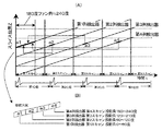
次に、図14を用いて、スキャン周期と心周期とが完全に同期する1例を説明する。なお、この図14(A)には、X線CT装置の投影データ形成装置207における分割投影データ収集のタイミングが示されている。また、図14(B)には、上記図14(A)に示す「180度+ファン角≒240度」の期間における分割投影データ収集タイミングの拡大図が示されている。
【0039】
この図14(A)の横軸は時間(t)であり、また、その縦軸は患者テーブル(図13における符号3を参照)の直線移動方向(Z軸)の位置である。また、この横軸下方には心電計206からのECG信号を図示し、時間方向(t)での心拍動の位置を示している。なお、この時の撮影条件は、螺旋ピッチ1、4列の検出器とし、スキャン周期と心周期の比が6:7の場合を想定した。ここで螺旋ピッチはZ軸方向の検出素子配列ピッチに対する比として定義される。
【0040】
この図14(A)の縦軸には、4本の斜め線が螺旋スキャンを行った場合の回転中心における4個の検出素子の軌跡を示している。また、検出素子の中心軌跡上の太線は、上記の実施の形態でも説明した、心時相の等しい分割投影データを示しており、ここでは、それぞれの分割投影データをal,a2,a3,a4とした。また、ここでは、分割投影データの収集方法が理解しやすいように、第1スキャン目に収集後の投影データを示し、図14(B)の下方の4つに区切られた方形は、収集後の投影データの拡大図であり、区切られたそれぞれの部分は収集された各々の分割投影データを示し、かつ、図中には、それぞれの分割投影データの検出器データ、スキャン開始からのスキャン数、そして、投影角範囲を明示している。
【0041】
このようにスキャン周期と心周期の比が6:7の場合、第1列検出器の第1スキャン投影角0〜60度の分割投影データa1、第2列検出器の第2スキャン投影角60〜120度の分割投影データa2、第3列検出器の第3スキャン投影角120〜180度の分割投影データa3、そして、第4列検出器の第4スキャン投影角180〜240度の分割投影データa4は、それぞれがECG信号において同範囲の分割投影データであって、同じデータ幅を持った4個の分割投影データから画像再構成に必要となる180度にX線源のファン角を加えた投影角度(約240度)分の投影データの収集に成功していることが明らかであろう。
【0042】
以上のアルゴリズムを用いて収集した投影データを画像再構成することにより、時間分解能がスキャンタイムの6分の1、且つモーションアーチファクトが少ない再構成画像を得ることが可能である。なお、上記図14の撮影条件では、本来、モーションアーチファクトが少ない投影データを形成することが可能であるので、この撮影条件を、ここでは理想の条件とする。
【0043】
しかし、上記図14で説明した投影データ収集法を適用できる条件は、スキャン周期と心周期の比が6:7の場合に限られており、この比とは異なる条件下で上記図14の投影データ収集法を適用した場合、心時相の等しい分割投影データを収集することができず、モーションアーチフアクトが少ない再構成画像を得ることは不可能である。
【0044】
上記の問題点に対する対策として、例えば、スキャンタイムを機械的に変更して、理想的な条件に近づけることも可能であるが、しかしながら、機械的変更により微調整できるスキャンタイムの範囲には限界があり、そのため、心時相の等しい分割投影データを収集することはできず、モーションアーチファクトが少ない再構成画像を得ることは不可能である。
【0045】
そこで、本発明では、分割投影データの分割数および分割投影データ幅を患者の心周期によって調整することによって、モーションアーチファクトが少ない再構成画像を得る投影データ収集法を提案するものであり、その詳細について、以下に図15を用いて説明する。
【0046】
この図15に示される内容は、上記図14と同様である。但し、撮影条件は螺旋ピッチ1、4列検出器とし、スキャン周期と心周期の比が36:43の場合を想定している。この比は、上記に説明した理想の条件と比べて、X線源が10度移動するのに要する時間だけスキャンタイムよりも心周期が長い場合の比である。また、収集する分割投影データをそれぞれb1,b2,b3,b4とした。
【0047】
スキャン周期と心周期の比が36:43の場合、第1列検出器の第1スキャン投影角0〜70度の分割投影データb1、第2列検出器の第2スキャン投影角70〜140度の分割投影データb2、第3列検出器の第3スキャン投影角140〜210度の分割投影データb3、そして、第4列検出器の第4スキャン投影角210〜240度の分割投影データb4とを組み合わせて、画像再構成に必要となる180度にX線源のファン角を加えた投影角度(約240度)分の投影データを収集している(図15(B)の拡大図参照)。
【0048】
この図15の分割投影データ収集法は、上記図14の場合と比べて、分割投影データb1、b2、b3のデータ幅をそれぞれ10度ずつ増加させ、一方、b4のデータ幅をb1、b2、b3のデータ幅の増加角度の合計である30度だけ減少させ、30度としたのが特徴である。またb2、b3、b4の分割投影データ開始角度をそれぞれ、10度,20度,30度ずつ増加させ、これにより、b1、b2、b3、b4はそれぞれ心時相の等しい分割投影データとなっている(図15(A)最下段のECG信号(心拍信号)を参照)。
【0049】
この図15に示すように、分割投影データのデータ幅を調整する分割投影データ収集法を用いて収集した投影データを画像再構成することによれば、時間分解能がスキャンタイムの36分の7、且つ、モーションアーチフアクトが少ない再構成画像を得ることが可能となる。
【0050】
このように、上記図15では、スキャンタイムと心周期の比が36:43の場合(理想の条件と比べて、X線源が10度移動するのに要する時間だけスキャンタイムよりも心周期が長い場合の比)の分割投影データ収集法を示したが、さらにスキャンタイムと心周期の差が大きい場合でも、同様に、収集する分割投影データの数を変更することによって、心時相の等しい投影データを収集することが可能である。
【0051】
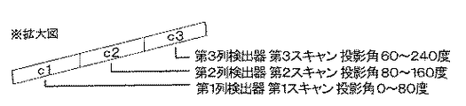
図16には、スキャンタイムと心周期の比が18:23の場合(理想の条件と比べて、X線源が20度移動するのに要する時間だけスキャンタイムよりも心周期が長い場合の比)の分割投影データ収集法を示した。なお、ここでは、説明の重複を避けるため、拡大図のみを図示し、分割投影データをそれぞれc1、c2、c3とした。そして、これら分割投影データc1、c2、c3のデータ幅をそれぞれ20度づつ増加させ、収集する分割投影データを3個に減少させることによって、やはり上記と同様に、モーションアーチファクトが少ない投影データを得ることが可能となる。
【0052】
この図16の分割投影データのデータ幅を調整する分割投影データ収集法を用いて収集した投影データを画像再構成することにより、時間分解能がスキャンタイムの9分の2、且つ、モーションアーチフアクトが少ない再構成画像を得ることが可能である。
【0053】
また、以上に述べた図14〜図16で説明した以外のスキャン周期と心周期の比の場合でも、上記と同様に、患者の心周期に合わせて分割投影データの幅と分割投影データ数を調整し、心時相の等しい分割投影データを収集することによって、モーションアーチファクトの少ない投影データを形成することが可能である。
【0054】
しかし、あまりに理想の条件(即ち、スキャン周期と心周期の比が6:7)から外れた条件の場合、本発明を利用すると、得られる分割投影データ数が少なくなり、且つ、分割投影データ幅も大きくなり、得られる再構成画像のモーションアーチファクトは多くなる。そのため、よりモーションアーチファクトが少ない再構成画像を得るためには、測定時のスキャンタイムを予め理想の条件に近くなるように設定しておき、本発明を利用することが望ましい。
【0055】
また、分割投影データ収集を行うと、分割投影データの境界部分では心時相が急激に変化するため、心臓断層像を作成した際にモーションアーチファクトが発生する。この現象を解決するには、それぞれの分割投影データのデータ幅を広めに設定し、それぞれの分割投影データの境界付近のデータに重み付け処理を行い、隣り合う分割投影データの境界部分を足し合わせて重ねあわせるなどの手段が考えられる。
【0056】
また、不整脈など患者の心拍動が不規則になった場合でも、心電計から得られる心拍動の情報(即ち、上記のECG信号)を用いて分割投影データのデータ幅、収集してくるデータ数を調整することにより、本発明を利用することが可能である。
【0057】
続いて、上記のようにして得られた投影データ作成後の画像再構成方法について、図17,18,19,20を用いて説明する。すなわち、任意のスライス位置の心臓断層像を得るには、作成した投影データに幾つかの処理を施す必要がある。まず、図17には、心臓断層を得るまでの処理の流れを示した。前述の様に患者の心拍数、撮影条件から分割投影データの分割数、データ幅を求め(step11)、分割投影データを収集することによって投影データを作成する(step12)。なお、上記に説明した図14,15,16においては、一つの投影データの収集方法についての例を示したが、しかしながら実際には、スライス位置の異なる複数の投影データの収集も可能である。そこで、この複数の投影データの作成について、以下に、図18を用いて説明する。
【0058】
まず、図18には、上記図14で示した理想の条件における投影データの作成方法例を示した。4列の検出器のデータからスライス範囲の異なる3個の投影データを作成している。得られる投影データをR1,R2,R3とし、収集してきた分割投影データそれぞれについて、用いた検出器データ、スキャン開始からのスキャン数、投影角範囲を示した。また、第1スキャンを基準として、それ以前のスキャンをマイナスで示している。この3個の投影データからあるスライス位置における心臓断層像を得るための2種類の方法を説明する。
【0059】
1つ目の方法について、上記図17と共に図19を用いて説明する。この図19の縦軸はスライス方向位置を示しており、点線で示されたスライス位置の心臓断層像を求めることとする。そのため、まず、3個の投影データR1,R2,R3それぞれに対してZ軸方向の重み付け処理を行い(上記図17のstep13)、これにより、あるスライス位置の投影データを作成する。次に、処理後の投影データR1’、R2’,R3’のそれぞれに対して画像再構成を行い(step14)、スライス位置の異なる3個の心臓断層像を得る。そして、最終的に得られた3個の心臓断層像img1,img2,img3から、内挿、または外挿の補間処理(Z軸方向補間処理)を用いて(step15)、任意のスライス位置の心臓断層像imgを得ることができる。
【0060】
次に、2つ目の方法について、図20を用いて説明する。この方法では作成した3個の投影データR1,R2,R3から、内挿、または外挿を用いたスライス方向の補間を行い、任意のスライス位置の投影データR’を得る(Z軸方向補間処理)ものである(上記図17のstep16)。その次に、投影データR’に対して画像再構成を行う(step17)ことにより、任意のスライス位置の心臓断層像imgを得ることができる。
【0061】
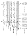
更に、図21を用いて、操作者が指示した任意の心時相における、画像再構成に必要な投影角度範囲の投影データを形成する手法について説明する。この図21は、上記図14と同様の条件における、各心時相の分割投影データの収集方法を示しており、すなわち、撮影条件は螺旋ピッチ1、4列検出器とし、スキャン周期と心周期の比が6:7の場合を想定したものである。前述した通り、この理想の条件下では、心時相が等しく、データ幅の等しい4個の分割投影データを用いてモーションアーチファクトの少ない再構成画像を得ることが可能である。
【0062】
図において、最も上方には心電波形(ECG信号)を示し、その下方には、1心拍を7個の心時相に分割した場合のそれぞれの心時相を、AからGの英字で表した。その下方には、4個の検出器それぞれの投影データを帯状の方形で図示しており、1スキャンを分割投影データの投影角度幅で区切り、各分割投影データを投影角度の小さい順番に1から6の数字で表している。また、分割投影データ収集方法が分かり易いように、第2列検出器の投影データは第2スキャンから、第3列検出器の投影データは第3スキャンから、第4列検出喪の投影データは第4スキャンから収集されている様子を図示している。また、この図からは、スキャン周期と心周期との比が6:7の条件下であるので、スキャンが進むに連れて、各検出器の分割投影データ1〜6の心時相が1心時相ずれることが分かるであろう。また、図の最も下方には、分割投影データ収集後の投影データを図示した。例えば、Aの心時相の投影データを形成する場合、縦に直列に並ぶ4個の分割投影データ(二重線で囲まれた部分)を収集し、画像再構成に必要な投影データを得ることが可能である。また、同様にB、Gの心時相についても投影データ形成の例が図示されている。
【0063】
次に、任意の心時相の投影データを形成する一例として、心時相Aと心時相Bのちょうど中間の心時相をもった投影データを形成することを考える。この場合、まず、それぞれの検出器の投影データにおける分割投影データの先頭投影角度を、分割投影データの投影角度範囲の半分の角度(30度)だけX線源の進行方向へ移動させる。各々の検出器における先頭投影角度変更後の投影データを、変更前の投影データ列の下方に示し、各分割投影データを1.5、2.5、…6.5とした。
【0064】
この場合にも、上記した心時相Aの投影データを形成した場合と同様に、分割投影データの先頭投影角度の移動後の分割投影データを収集することで、心時相Aと心時相Bの中間の心時相における投影データを形成することができる。収集後の投影データをこの図21下方に、心時相A〜Bの投影データとして図示した。また、同様の収集方法で、心時相Bと心時相Cの中間の心時相の投影データなど、各心時相の中間の心時相の投影データを収集することが可能である。
【0065】
このように、分割投影データの先頭投影角度を移動させることにより、各心時相の中間の心時相の投影データを収集する方法を説明したが、これによれば、分割投影データの先頭投影角度の移動量を変更することにより、任意の心時相の投影データを形成することが可能であることがわかる。
【0066】
また、分割投影データの先頭投影角度の移動量が任意の投影角度だけ異なる投影データを複数作成し、それぞれを画像再構成することによって、任意の時間間隔の心時相における心臓断層像を複数枚作成することが可能であることもわかる。
【0067】
また、同様の方法で体軸方向(スライス方向)の異なる複数箇所の位置においても、任意の時間間隔の心時相における再構成画像を作成し、同じ心時相を持った再構成画像を体軸方向に集合することによって、任意の時間間隔の心時相における心臓全体の断層画像、即ち、三次元画像を作成することが可能であることもわかるであろう。
【0068】
また、上記のようにして得られた三次元画像を、心時相の順番に表示装置(図13の符号206を参照)上に表示することにより、途切れなくスムーズに拍動する心臓の三次元動画、即ち、四次元画像を得ることが可能であることがわかる。
【0069】
【発明の効果】
以上に詳細に説明したように、本発明になるX線CT装置によれば、特に螺旋スキャン時における投影データの不連続性を解消し、特に、これにより得られる心臓断層像は、心臓のモーションアーチファクトが少ない良好な断層画像を得ることが可能となる。
【0070】
また、上記本発明になるX線CT装置により得られる連続性の分割投影データを利用して、任意のスライス位置及び心時相の投影データを形成することが可能であり、これらを適宜組み合わせ、あるいは、集合することにより、任意の時間間隔の心時相における心臓全体の断層画像、その三次元画像、さらには、心臓の三次元動画などを、モーションアーチファクトを低減し、途切れなくスムーズに作成することが可能となる。
【図面の簡単な説明】
【図1】 本発明の実施例の基本構成を示すブロック図である。
【図2】 心電波形の説明図である。
【図3】 レトロスペクティブECGゲートの説明図である。
【図4】 レトロスペクティブECGゲートの説明図である。
【図5】 本発明の流れを示す図である。
【図6】 複数列検出器におけるレトロスペクティプECGゲートの説明図である。
【図7】 複数列検出器におけるレトロスペクティプECGゲートの説明図である。
【図8】 補間方法の説明図である。
【図9】 複数列検出器におけるレトロスペクティブECGゲートの説明図である。
【図10】 不連続投影データの説明図である。
【図11】 不連続投影データの説明図である。
【図12】 不連続領域の補間説明図である。
【図13】 本発明の一実施の形態になるマルチスライスX線CT装置の構成の概略を示す図である。
【図14】 上記本発明のX線CT装置における投影データ形成装置の分割投影データ収集の一例を示す図である。
【図15】 上記本発明のX線CT装置における投影データ形成装置の分割投影データ収集の他の一例を示す図である。
【図16】 やはり、上記本発明のX線CT装置における投影データ形成装置の分割投影データ収集のさらに他の一例を示す図である。
【図17】 上記本発明のX線CT装置における投影データ形成装置と画像処理装置が行う処理の流れを示す図である。
【図18】上記図17で示される処理の詳細を説明する図である。
【図19】 やはり、上記図17で示される処理の詳細を説明する図である。
【図20】 やはり、上記図17で示される処理の詳細を説明する図である。
【図21】 本発明のX線CT装置における投影データ形成装置での、任意の心時相をもった分割投影データ収集の一例を示す図である。
【符号の説明】
10 X線CT装置
11 算出ユニット
12 被検体
13 処理装置
80,81 検出器の軌跡
202 スキャナガントリ部
206 心電計
207 投影データ形成装置[0001]
BACKGROUND OF THE INVENTION
The present invention relates to an X-ray CT (Computed Tomography) apparatus, and more particularly to an X-ray CT apparatus suitable for cardiac ECG gate imaging.
[0002]
[Prior art]
In general, when an image is taken using an X-ray CT apparatus due to the pulsation of a human heart, motion artifacts appear in a tomographic image, which is not preferable for diagnosis. In order not to generate motion artifacts, it can be solved by increasing the scanning speed.
[0003]
In an X-ray CT apparatus with a current scan speed of about 1 second, the X-ray exposure is performed intermittently based on the electrocardiographic information of the subject, so that projections at different projection angles with the same heartbeat time phase are performed. Data is measured for one scan, and the image is reconstructed using this data, which is generally called an ECG trigger, prospective, or the like. In addition, a method has been proposed in which projection data is obtained (taken) without synchronizing with the cardiac cycle, and after obtaining the projection data, an image is reconstructed by combining projection data having the same heartbeat time phase. This is generally called ECG gate photography or retrospective.
[0004]
Note that the cardiac imaging method described above is mainly a method in which imaging is performed with the table stopped (referred to as normal scanning).
[0005]
In general, in order to observe the state of the heart beat, the cardiac tomogram obtained as described above or a three-dimensional image obtained from a plurality of cardiac tomograms in the order of cardiac phases. Therefore, means for continuously displaying moving images of heart tomograms has been taken, and means for achieving synchronization with the heartbeat cycle by finely adjusting the scan time has been taken.
[0006]
[Problems to be solved by the invention]
However, since the cardiac imaging method described above is premised on imaging (normal scan) with the table stopped, in the case of spiral scanning in which the table is moved and imaged, there is discontinuity in the projection data. This will result in clinically unfavorable images.
[0007]
In addition, when obtaining a moving image of a cardiac tomography, as described above, means for finely adjusting the scan time to synchronize with the heartbeat cycle has been adopted. There is a limit to the range of scan time that can be adjusted, and in the above-mentioned conventional technique, since one heartbeat was divided and the images in each cardiac phase were arranged, it was possible to create a smooth movie could not.
[0008]
Accordingly, an object of the present invention is to provide an X-ray CT apparatus capable of obtaining a wide range of tomographic images with reduced motion artifacts even when using a helical scan.
[0009]
Furthermore, in the present invention, even when a deviation occurs between the heart rate and the set value of the scan time, it is possible to obtain a tomographic image of a heart with little motion artifact (motion artifact) due to the heartbeat, and Another object of the present invention is to provide an X-ray CT apparatus capable of obtaining a smoother heart tomographic moving image than in the prior art.
[0010]
[Means for Solving the Problems]
The present invention relates to an X-ray CT apparatus having an ECG gate function for a heart, a synchronization unit for obtaining a synchronization signal of a heartbeat period and a scan period from a heart rate of a subject and a scan speed of a CT scanner, By adjusting at least one of the head projection angle of the projection data, the number of projection data, and the data width based on the synchronization signal, the projection equal to an arbitrary heartbeat time phase and necessary for image reconstruction An X-ray CT apparatus comprising: a projection data calculation unit that forms projection data in an angle range is disclosed.
Further, according to the present invention, when the projection data calculation unit collects projection data having a heartbeat time phase from each scan cycle during the helical scan, the interpolation that compensates the discontinuous region in the bed direction caused by the heartbeat and the scan cycle with the opposing data is performed. There is disclosed an X-ray CT apparatus having means for calculating discontinuous projection data in the bed direction by this interpolation.
Further, according to the present invention, when the projection data calculation unit collects projection data having a matching heartbeat time phase from each scan cycle during the helical scan, the discontinuous region in the bed direction caused by the heartbeat and the scan cycle is detected as a nearby heartbeat time phase. Discloses an X-ray CT apparatus having interpolation means that compensates by interpolation using the same projection data, and that calculates discontinuous projection data in the bed direction by this correction.
[0011]
Furthermore, the present invention is characterized in that the projection data calculation unit further obtains and displays a cardiac tomographic movie by creating a cardiac tomographic image at an arbitrary slice position from the collected projection data having a matching heartbeat time phase. An X-ray CT apparatus is disclosed.
Furthermore, the present invention is characterized in that the projection data calculation unit further obtains and displays a cardiac tomographic video by creating a cardiac tomographic image of an arbitrary heartbeat time phase from the collected projection data with a matching heartbeat time phase. An X-ray CT apparatus is disclosed.
Further, according to the present invention, the projection data calculating unit further obtains a three-dimensional image of the heart by collecting a plurality of obtained cardiac tomographic images of any heartbeat time phase in the body axis direction for each heartbeat time phase. An X-ray CT apparatus is disclosed.
Further, the present invention provides the X-ray CT apparatus, wherein the projection data calculation unit further obtains a moving image of a three-dimensional image of the heart by displaying the obtained three-dimensional image in order of heartbeat time phases. Disclose.
[0012]
DETAILED DESCRIPTION OF THE INVENTION
FIG. 1 shows a basic configuration of the present invention, and a patient displaying a tomographic image of a subject 12 and a projection data calculation unit 11 that collects projection data that matches a heartbeat time phase from each scanning cycle with an X-ray CT scanner 10. A
[0013]
FIG. 2 shows the waveform names of the electrocardiograms used for explanation in future examples. The ECG with the highest value is called the R wave, and the front and back are called the Q and S waves. Please refer to medical books for details.
[0014]
FIG. 3 illustrates a retrospective ECG gate imaging method. FIG. 3 shows the case where the bed does not move during scanning and the X-ray detector is in one row. As shown in FIG. 3, when the scan cycle is 1 second and the heart rate cycle (RR time) of the subject is 0.75 seconds, the scan time phase and the heart rate after 3 scans (after 4 heartbeats in terms of heartbeat) The phase will be the same. Since the heart repeats the heartbeat four times during the three-scan cycle, projection data having the same heartbeat time phase is present four times in the three scans. In the retrospective ECG gate, data having the same heartbeat time phase and different projection angles may be collected for one scan period. Since the projection data for one scan period is collected from the four heartbeat periods, the projection data collected per one heartbeat period can be collected by ½ redundancy in terms of the projection angle.
[0015]
That is, electrocardiographic waveforms R1 and R2 are generated in the first period, R3 is generated in the second period, and R4 and R5 are generated in the third period. The motion of the heart becomes nearly stationary when it expands, which is when the electrocardiographic waveforms R1-R5 occur. Starting from this point in time, projection data of ½π is created at projection angles, and these are connected in the order of projection angles, so that almost stationary projection data of one heart can be obtained. The projection data of a, b, c, and d in FIG. 3 indicate partial projection data when images are taken at a projection angle of 1 / 2π with R1, R2, R3, and R4 as starting points, respectively. When this is executed, projection data as shown in FIG. This data is collected from each heartbeat cycle by 1 / 2π after the R wave, and the projection angles are all different. That is, it is equivalent to scanning 360 degrees in a time for scanning a projection angle of 1 / 2π. As shown in FIG. 4B, the data a and b are collected from the first scan period, the data d is collected from the third scan period, and the data C is collected from the second scan period.
[0016]
That is, FIG. 4A shows a case where partial projection data a, b, c, and d in FIG. 3 are arranged in the order of
[0017]
This retrospective ECG gate scans 360 degrees with a scan time of 1 / 2π projection angle (in the example of Fig. 3), so the theoretical scan time was taken at 0.25 seconds. Even in the current third generation CT of about 1 second per scan, the heart can be imaged at high speed. Also, faster scanning can be performed depending on the scan time and the heartbeat time.
[0018]
FIG. 5 shows a rough flow when performing cardiac imaging. First, in
[0019]
FIG. 6 shows a case where the letoscopic ECG gate scan of FIG. 3 is applied to a spiral scan in which the table moves during the scan. In FIG. 6, the detector will be described using a four-row detector. In FIG. 6, the scan cycle is 1 second and the heartbeat cycle is 0.75 seconds. The vertical axis in the figure indicates the bet direction, and the horizontal axis indicates the projection angle. The locus of the detector measures the center of each detector. As the helical scan pitch, a
[0020]
6, when projection data having the same heartbeat time phase is collected as in FIG. 3, the hatched area in FIG. 6 corresponds.
[0021]
In the case of FIG. 6 as well, since the heartbeat cycle is performed four times in the three scan cycles, it is possible to obtain projection data for one scan if ½π projection data is collected. In the case of FIG. 6, since a four-row detector is used, the projection data to be collected waits for the width of the detector, and this is indicated by a hatched rectangle in the figure. In other words, if it is within a rectangle, projection data can be calculated at an arbitrary slice position by interpolation between projection data obtained by neighboring detectors. That is, the scan is 1 second per cycle, and the projection angle is 0 to 2π. This scan is performed for three cycles to obtain projection data a, b, c, d for each of the electrocardiographic waveforms R1 to R4.
[0022]
In FIG. 7, the rectangle is translated into the first scan so that the projection data obtained in each scan period of FIG. 6 can be drawn in one scan. That is, the projection data are arranged in the order of a, d, c, and b between the projection angles 0 to 2π. In FIG. 7, the projection data collected from each period is drawn in a staircase pattern because the collected data is shifted in the bet direction because of the spiral scan. For example, the projection data at the slice position SP shown in FIG. 7 can be calculated because it is included in the hatched rectangle at any projection angle. The interpolation method can be realized by using linear interpolation using a weight corresponding to a simple distance as shown in FIG.
[0023]
In FIG. 8, for the sake of explanation, the projection data of the portion π to 3 / 2π of FIG. 7 is extracted. In this case, projection data at a desired slice position is calculated from the 3-row and 4-row detectors. That is, FIG. 8A shows a
[0024]
6 and 7 represent up to the third scan, but in FIG. 9, the projection data that can be collected in the case of further scanning is represented by translation in the first scan. If scanning is continued, projection data having the same heartbeat time phase and different projection angles can be calculated at various slice positions as shown in FIG. That is, the projection data a, b, c, and d are projection data corresponding to the first to third periods, respectively, and e, f, g, and h are projection data corresponding to the fourth to sixth periods. It is shown. In this case, since the slice positions 90 to 93 extend over any projection data, image data can be created at an arbitrary slice position.
[0025]
Next, a case where heartbeats are different will be described. When the scan cycle is 1 second, the heartbeat cycle is 0.8 seconds, and the spiral scan pitch is 1, the scan is synchronized with 4 cycles, and the heartbeat cycle is synchronized with 5 cycles. In this case, the collected projection data is 2 / 5π each. In the present invention, the width of projection data to be collected and the like is set by a projection data calculation unit.
[0026]
As described with reference to FIGS. 6, 7, and 8, the above example is illustrated in FIG. 10. FIG. 10 When calculating projection data at the slice position SP, a discontinuous area 100 of projection data in which the slice data is not included because the slice position is not included in the rectangle in the
[0027]
In the present invention, the above-described problems are solved as follows. FIG. 12A shows a retrospective ECG gate scan method in the case where the scan is repeated for 1 second and the cardiac cycle is repeated at 0.8 seconds. As is clear from FIG. 12A, for example, discontinuity of projection data occurs in the section of 4 / 5π to 6 / 5π (discontinuous region A) at the slice position SP1. Further, at the slice position SP2, a discontinuous region of projection data is generated in a section of 8 / 5π to 2π (discontinuous region B). If there is discontinuity in projection data, projection data at a desired slice position cannot be calculated. Therefore, if an image is obtained by performing reconstruction processing as it is, an artifact or a significantly deteriorated image is obtained.
[0028]
As shown in FIG. 12A, 4 / 5π to 6 / 5π and 8 / 5π to 2π are in a 180-degree opposed relationship. The facing relationship is an X-ray path that passes through the same region, and the X-ray incidents are shifted from each other by 180 degrees. That is, the 180-degree facing data is theoretically exactly the same in the scan where the bet is stationary.
[0029]
In the facing relationship in FIG. 12A, since the spiral scan is used, even in the facing relationship, the bet directions are different, and thus they are not the same. However, it is a very effective correction method to eliminate the discontinuous area by replacing the discontinuous area with projection data facing 180 degrees. This is because retrospective ECG gate imaging is based on the premise that projection data having the same heartbeat time phase is collected in order to suppress heart motion artifacts as much as possible. For this reason, when replacing some projection data with the discontinuous area A shown in FIG. 12A, projection data having a 180-degree opposed positional relationship and the same heartbeat time phase must be used. Since the square hatched areas shown in FIG. 12 (a) are all data having the same heartbeat time phase, if projection data having an opposing relationship is used from these, the 180 ° opposing positional relationship and the heartbeat Projection data having the same time phase is used.
[0030]
FIG. 12B shows an example in which projection data having the above-mentioned facing relationship and the same heartbeat time phase is embedded in the discontinuous region. In FIG. 12B, the discontinuous region has disappeared due to the embedding process, and projection data can be calculated at the slice position SP1. Conversely, in the discontinuous region B, the section of 8 / 5π to 2π is discontinuous, but this is also solved by embedding data of 4 / 5π to 6 / 5π that are in a 180-degree facing relationship, and the slice position SP2 Projection data can be calculated.
[0031]
Although the above uses projection data having an opposing relationship, the projection data can be calculated even if the projection data of the discontinuous region at the slice position SP1 is calculated from the rectangular hatched regions C and D by linear interpolation. Although the reliability is lower than that of the method using the 180-degree opposed data, data having the same heartbeat time phase is used, which can be said to be suitable for cardiac imaging.
[0032]
In the above description, a method using data having the same heartbeat time phase with 180 degrees opposite relationship and a method using linear interpolation or the like using adjacent projection data are employed. Since the same data is used, the obtained cardiac tomogram can obtain an image with few heart motion artifacts.
[0033]
Next, an X-ray CT apparatus having a cardiac ECG gate function according to another embodiment of the present invention, which is obtained from the above-described continuous region projection data obtained by the present invention, that is, from each scan period. An X-ray CT apparatus that can obtain a smoother heart tomographic movie by collecting projection data that matches heartbeat time phases and obtaining a heart tomogram will be described.
[0034]
First, as shown in FIG. 13, this apparatus uses a
[0035]
That is, the
[0036]
The X-ray intensity generated from the
[0037]
In the X-ray CT apparatus according to the present invention, the schematic configuration of which has been described above, X-rays are irradiated from the
[0038]
Next, an example in which the scan cycle and the cardiac cycle are completely synchronized will be described with reference to FIG. FIG. 14A shows the timing of collecting divided projection data in the projection
[0039]
The horizontal axis of this FIG. 14 (A) is time (t), and the vertical axis | shaft is the position of the linear movement direction (Z-axis) of a patient table (refer the code |
[0040]
The vertical axis of FIG. 14A shows the trajectories of the four detection elements at the center of rotation when the four diagonal lines perform a helical scan. Further, the thick line on the center locus of the detection element indicates the divided projection data having the same cardiac phase as described in the above embodiment. Here, the divided projection data are represented by al, a2, a3, a4. It was. Further, here, in order to make it easy to understand the method of collecting the divided projection data, the projection data after collection is shown in the first scan, and the rectangle divided into the lower four parts in FIG. FIG. 4 is an enlarged view of the projection data, and each divided part shows the collected divided projection data, and in the figure, the detector data of each divided projection data, the number of scans from the start of scanning And the projection angle range is specified.
[0041]
Thus, when the ratio of the scan cycle to the cardiac cycle is 6: 7, the divided projection data a1 of the first scan projection angle of 0 to 60 degrees of the first row detector, and the second scan projection angle 60 of the second row detector. -120 degree divided projection data a2, third row detector third scan projection angle 120-180 degree divided projection data a3, and fourth row detector fourth scan projection angle 180-240 degree divided projection The data a4 is divided projection data within the same range in the ECG signal, and the fan angle of the X-ray source is added to 180 degrees necessary for image reconstruction from four divided projection data having the same data width. It will be apparent that the projection data for the projection angle (about 240 degrees) has been successfully collected.
[0042]
By reconstructing the projection data collected using the above algorithm, it is possible to obtain a reconstructed image with a time resolution of one-sixth of the scan time and few motion artifacts. Note that, since the projection data of FIG. 14 can originally form projection data with few motion artifacts, this imaging condition is an ideal condition here.
[0043]
However, the conditions under which the projection data collection method described with reference to FIG. 14 can be applied are limited to the case where the ratio of the scan cycle to the cardiac cycle is 6: 7. When the data collection method is applied, it is impossible to collect divided projection data having the same cardiac phase, and it is impossible to obtain a reconstructed image with less motion artifact.
[0044]
As a countermeasure against the above problems, for example, it is possible to change the scan time mechanically to approach the ideal condition, however, there is a limit to the range of scan time that can be finely adjusted by mechanical change. Therefore, it is impossible to collect divided projection data having the same cardiac phase, and it is impossible to obtain a reconstructed image with less motion artifacts.
[0045]
Therefore, the present invention proposes a projection data collection method for obtaining a reconstructed image with few motion artifacts by adjusting the number of divisions of divided projection data and the division projection data width according to the cardiac cycle of the patient. Will be described below with reference to FIG.
[0046]
The contents shown in FIG. 15 are the same as those in FIG. However, it is assumed that the imaging condition is a
[0047]
When the ratio of the scan cycle to the cardiac cycle is 36:43, the divided projection data b1 with the first scan projection angle of 0 to 70 degrees of the first row detector, and the second scan projection angle of 70 to 140 degrees with the second row detector. Divided projection data b2 of the third row detector, divided projection data b3 of the third scan projection angle 140 to 210 degrees of the third row detector, and divided projection data b4 of the fourth
[0048]
The divided projection data collection method of FIG. 15 increases the data widths of the divided projection data b1, b2, and b3 by 10 degrees, respectively, while the data width of b4 is b1, b2, The b3 data width is decreased by 30 degrees, which is the total increase angle of the data width, and is 30 degrees. In addition, the divided projection data start angles of b2, b3, and b4 are increased by 10 degrees, 20 degrees, and 30 degrees, respectively, so that b1, b2, b3, and b4 are divided projection data having the same cardiac phase. (See the ECG signal (heart rate signal) at the bottom of FIG. 15A).
[0049]
As shown in FIG. 15, according to the image reconstruction of the projection data collected using the divided projection data collection method for adjusting the data width of the divided projection data, the time resolution is 7/36 of the scan time, In addition, it is possible to obtain a reconstructed image with less motion artifact.
[0050]
Thus, in FIG. 15 above, when the ratio of the scan time to the cardiac cycle is 36:43 (compared to the ideal condition, the cardiac cycle is longer than the scan time by the time required for the X-ray source to move 10 degrees. Even when the difference between the scan time and the cardiac cycle is larger, similarly, the cardiac phase is equal by changing the number of divided projection data to be collected. It is possible to collect projection data.
[0051]
FIG. 16 shows the case where the ratio of the scan time to the cardiac cycle is 18:23 (compared to the case where the cardiac cycle is longer than the scan time by the time required for the X-ray source to move 20 degrees compared to the ideal condition). ) Shows the method of collecting divided projection data. Here, in order to avoid duplication of explanation, only enlarged views are illustrated, and the divided projection data are c1, c2, and c3, respectively. Then, by increasing the data width of each of the divided projection data c1, c2, and c3 by 20 degrees and reducing the collected divided projection data to three, the projection data with few motion artifacts is obtained as described above. It becomes possible.
[0052]
By reconstructing the image of the projection data collected using the divided projection data collection method for adjusting the data width of the divided projection data in FIG. 16, the time resolution is two-ninths of the scan time and the motion artifact is obtained. It is possible to obtain a reconstructed image with less.
[0053]
Further, even in the case of the ratio between the scan cycle and the cardiac cycle other than those described in FIGS. 14 to 16 described above, the width of the divided projection data and the number of the divided projection data are set in accordance with the cardiac cycle of the patient as described above. By adjusting and collecting divided projection data having the same cardiac phase, it is possible to form projection data with less motion artifacts.
[0054]
However, when the present invention is used in a condition that deviates from an ideal condition (that is, the ratio of the scan cycle to the cardiac cycle is 6: 7), the number of divided projection data obtained is reduced and the divided projection data width is obtained. And the resulting reconstructed image has more motion artifacts. Therefore, in order to obtain a reconstructed image with fewer motion artifacts, it is desirable to use the present invention by setting the scan time at the time of measurement to be close to an ideal condition in advance.
[0055]
Further, when the divided projection data is collected, the cardiac time phase changes abruptly at the boundary portion of the divided projection data, so that a motion artifact occurs when a cardiac tomogram is created. In order to solve this phenomenon, the data width of each divided projection data is set wider, weighting processing is performed on the data near the boundary of each divided projection data, and the boundary portions of adjacent divided projection data are added together. Means such as overlapping can be considered.
[0056]
Further, even when the heartbeat of the patient becomes irregular, such as an arrhythmia, the data width of the divided projection data and the data collected by using the heartbeat information obtained from the electrocardiograph (that is, the above ECG signal) The present invention can be used by adjusting the number.
[0057]
Next, an image reconstruction method after creating projection data obtained as described above will be described with reference to FIGS. That is, in order to obtain a cardiac tomogram at an arbitrary slice position, it is necessary to perform some processing on the created projection data. First, FIG. 17 shows the flow of processing until a cardiac tomography is obtained. As described above, the division number of divided projection data and the data width are obtained from the patient's heart rate and imaging conditions (step 11), and the projection data is created by collecting the divided projection data (step 12). In FIGS. 14, 15, and 16 described above, an example of a method for collecting one projection data is shown. However, actually, a plurality of projection data having different slice positions can be collected. Therefore, the creation of the plurality of projection data will be described below with reference to FIG.
[0058]
First, FIG. 18 shows an example of a method for creating projection data under the ideal conditions shown in FIG. Three projection data with different slice ranges are generated from the data of the detectors in four rows. The obtained projection data are R1, R2, and R3, and for each of the collected divided projection data, the detector data used, the number of scans from the start of scanning, and the projection angle range are shown. Further, with the first scan as a reference, the previous scan is indicated by minus. Two methods for obtaining a cardiac tomogram at a certain slice position from these three projection data will be described.
[0059]
The first method will be described with reference to FIG. The vertical axis in FIG. 19 indicates the slice direction position, and a tomographic image of the heart at the slice position indicated by the dotted line is obtained. Therefore, first, weighting processing in the Z-axis direction is performed on each of the three projection data R1, R2, and R3 (
[0060]
Next, the second method will be described with reference to FIG. In this method, interpolation in the slice direction using interpolation or extrapolation is performed from the three created projection data R1, R2, and R3 to obtain projection data R ′ at an arbitrary slice position (Z-axis direction interpolation processing). (
[0061]
Furthermore, a method for forming projection data in a projection angle range necessary for image reconstruction in an arbitrary cardiac time phase designated by the operator will be described with reference to FIG. FIG. 21 shows a method of collecting divided projection data for each cardiac phase under the same conditions as in FIG. 14. That is, the imaging condition is a
[0062]
In the figure, an electrocardiogram waveform (ECG signal) is shown in the uppermost part, and below that, each cardiac time phase when one heartbeat is divided into seven cardiac time phases is represented by alphabetic characters from A to G. did. Below that, the projection data of each of the four detectors is shown as a band-shaped square. One scan is divided by the projection angle width of the divided projection data, and each divided projection data is divided into 1 in ascending order of the projection angle. It is represented by the
[0063]
Next, as an example of forming projection data of an arbitrary cardiac phase, let us consider forming projection data having a cardiac phase just between cardiac phase A and cardiac phase B. In this case, first, the head projection angle of the divided projection data in the projection data of each detector is moved in the advancing direction of the X-ray source by half the angle (30 degrees) of the projection angle range of the divided projection data. The projection data after the change of the leading projection angle in each detector is shown below the projection data string before the change, and each divided projection data is 1.5, 2.5,... 6.5.
[0064]
Also in this case, similarly to the case where the projection data of the cardiac phase A is formed, by collecting the divided projection data after moving the head projection angle of the divided projection data, the cardiac phase A and the cardiac phase are collected. Projection data in the middle cardiac phase of B can be formed. The projection data after collection is shown as projection data of cardiac phases A to B below the FIG. In addition, it is possible to collect projection data of a cardiac phase that is intermediate between the cardiac phases, such as projection data of a cardiac phase that is intermediate between the cardiac phases B and C, by a similar collection method.
[0065]
As described above, the method for collecting the projection data of the cardiac phase intermediate between the cardiac phases by moving the leading projection angle of the divided projection data has been described. It can be seen that projection data of an arbitrary cardiac time phase can be formed by changing the amount of movement of the angle.
[0066]
In addition, by creating multiple projection data in which the amount of movement of the leading projection angle of the divided projection data differs by an arbitrary projection angle, and reconstructing each image, multiple cardiac tomographic images in the cardiac time phase at any time interval It can also be seen that it can be created.
[0067]
In addition, a reconstructed image in the cardiac phase of an arbitrary time interval is created at multiple positions in the body axis direction (slice direction) by the same method, and a reconstructed image having the same cardiac phase is created. It will also be understood that by gathering in the axial direction, it is possible to create a tomographic image of the entire heart, ie, a three-dimensional image, in the cardiac phase at any time interval.
[0068]
Further, by displaying the three-dimensional image obtained as described above on the display device (see
[0069]
【The invention's effect】
As described above in detail, according to the X-ray CT apparatus of the present invention, the discontinuity of projection data is eliminated particularly during a helical scan, and in particular, the tomographic image obtained thereby is a motion of the heart. A good tomographic image with few artifacts can be obtained.
[0070]
Moreover, it is possible to form projection data of an arbitrary slice position and cardiac phase using the continuous division projection data obtained by the X-ray CT apparatus according to the present invention, and appropriately combine them. Or, by gathering, a tomographic image of the entire heart in a cardiac time phase at an arbitrary time interval, its three-dimensional image, and further, a three-dimensional moving image of the heart, etc. can be created smoothly and seamlessly with reduced motion artifacts. It becomes possible.
[Brief description of the drawings]
FIG. 1 is a block diagram showing a basic configuration of an embodiment of the present invention.
FIG. 2 is an explanatory diagram of an electrocardiogram waveform.
FIG. 3 is an explanatory diagram of a retrospective ECG gate.
FIG. 4 is an explanatory diagram of a retrospective ECG gate.
FIG. 5 is a diagram showing a flow of the present invention.
FIG. 6 is an explanatory diagram of a retrospective ECG gate in a multi-row detector.
FIG. 7 is an explanatory diagram of a retrospective ECG gate in a multi-row detector.
FIG. 8 is an explanatory diagram of an interpolation method.
FIG. 9 is an explanatory diagram of a retrospective ECG gate in a multi-row detector.
FIG. 10 is an explanatory diagram of discontinuous projection data.
FIG. 11 is an explanatory diagram of discontinuous projection data.
FIG. 12 is an explanatory diagram of interpolation of discontinuous regions.
FIG. 13 is a diagram showing a schematic configuration of a multi-slice X-ray CT apparatus according to an embodiment of the present invention.
FIG. 14 is a diagram showing an example of divided projection data collection of the projection data forming apparatus in the X-ray CT apparatus of the present invention.
FIG. 15 is a diagram showing another example of the divided projection data collection of the projection data forming apparatus in the X-ray CT apparatus of the present invention.
FIG. 16 is a view showing still another example of the divided projection data collection of the projection data forming apparatus in the X-ray CT apparatus of the present invention.
FIG. 17 is a diagram showing a flow of processing performed by the projection data forming apparatus and the image processing apparatus in the X-ray CT apparatus of the present invention.
FIG. 18 is a diagram for explaining the details of the processing shown in FIG. 17;
FIG. 19 is also a diagram for explaining the details of the processing shown in FIG.
20 is also a diagram for explaining the details of the processing shown in FIG.
FIG. 21 is a diagram showing an example of divided projection data collection having an arbitrary cardiac time phase in the projection data forming apparatus in the X-ray CT apparatus of the present invention.
[Explanation of symbols]
10 X-ray CT system
11 Calculation unit
12 Subject
13 Processing equipment
80, 81 Detector trajectory
202 Scanner gantry
206 ECG
207 Projection data forming apparatus
Claims (7)
Priority Applications (4)
| Application Number | Priority Date | Filing Date | Title |
|---|---|---|---|
| JP2001366017A JP4010802B2 (en) | 2001-03-09 | 2001-11-30 | X-ray CT system |
| CNB02823944XA CN100401984C (en) | 2001-11-30 | 2002-11-28 | Method and apparatus for making cardiac tomography and tomogram using x-ray CT apparatus |
| PCT/JP2002/012448 WO2003045247A1 (en) | 2001-11-30 | 2002-11-28 | Cardiac tomography and tomogram using x-ray ct apparatus |
| US10/496,420 US7006593B2 (en) | 2001-11-30 | 2002-11-28 | Method of producing cardiac tomogram and tomograph using x-ray ct apparatus |
Applications Claiming Priority (3)
| Application Number | Priority Date | Filing Date | Title |
|---|---|---|---|
| JP2001-67153 | 2001-03-09 | ||
| JP2001067153 | 2001-03-09 | ||
| JP2001366017A JP4010802B2 (en) | 2001-03-09 | 2001-11-30 | X-ray CT system |
Publications (3)
| Publication Number | Publication Date |
|---|---|
| JP2002330961A JP2002330961A (en) | 2002-11-19 |
| JP2002330961A5 JP2002330961A5 (en) | 2005-07-28 |
| JP4010802B2 true JP4010802B2 (en) | 2007-11-21 |
Family
ID=26610966
Family Applications (1)
| Application Number | Title | Priority Date | Filing Date |
|---|---|---|---|
| JP2001366017A Expired - Lifetime JP4010802B2 (en) | 2001-03-09 | 2001-11-30 | X-ray CT system |
Country Status (1)
| Country | Link |
|---|---|
| JP (1) | JP4010802B2 (en) |
Families Citing this family (10)
| Publication number | Priority date | Publication date | Assignee | Title |
|---|---|---|---|---|
| JP4493323B2 (en) * | 2003-11-28 | 2010-06-30 | 株式会社日立メディコ | Medical image display device |
| CN1968654B (en) | 2004-06-16 | 2012-09-26 | 株式会社日立医药 | Radiotomograph |
| JP2007029166A (en) * | 2005-07-22 | 2007-02-08 | Morita Mfg Co Ltd | Image processor |
| JP5269386B2 (en) * | 2006-10-23 | 2013-08-21 | 株式会社東芝 | X-ray computed tomography apparatus and medical imaging apparatus |
| US8229187B2 (en) * | 2007-04-11 | 2012-07-24 | General Electric Company | Respiratory motion extraction from tomographic projection and image data |
| JP5220368B2 (en) * | 2007-09-03 | 2013-06-26 | ジーイー・メディカル・システムズ・グローバル・テクノロジー・カンパニー・エルエルシー | X-ray CT system |
| CN101467888B (en) | 2007-12-28 | 2013-03-27 | Ge医疗系统环球技术有限公司 | X ray CT device and X ray tube current determining method |
| DE102008008601B4 (en) * | 2008-02-12 | 2010-07-29 | Siemens Aktiengesellschaft | Method for processing medical image data for the layered imaging of a structure during free breathing |
| JP5346734B2 (en) * | 2009-08-07 | 2013-11-20 | 株式会社日立メディコ | Image processing device |
| KR101964844B1 (en) * | 2016-07-22 | 2019-04-03 | 주식회사 바텍 | Apparatus and Method for CT Image Reconstruction Based on Motion Compensation |
-
2001
- 2001-11-30 JP JP2001366017A patent/JP4010802B2/en not_active Expired - Lifetime
Also Published As
| Publication number | Publication date |
|---|---|
| JP2002330961A (en) | 2002-11-19 |
Similar Documents
| Publication | Publication Date | Title |
|---|---|---|
| US7006593B2 (en) | Method of producing cardiac tomogram and tomograph using x-ray ct apparatus | |
| EP1088517B1 (en) | Method and apparatus for motion-free cardiac CT imaging | |
| JP4393086B2 (en) | X-ray computed tomography system | |
| US7570733B2 (en) | Step-and-shoot cardiac CT imaging | |
| US7313215B2 (en) | Step-and-shoot cardiac CT imaging | |
| JP4796739B2 (en) | Heart spiral half-scan reconstruction for CT with multiple detector rows | |
| JP3637074B2 (en) | Helical scan computed tomography system | |
| JP5214916B2 (en) | X-ray CT apparatus and data processing method thereof | |
| Flohr et al. | Image reconstruction and performance evaluation for ECG‐gated spiral scanning with a 16‐slice CT system | |
| JP2004509691A (en) | Multi-sector reconstruction by temporal control for multi-slice helical computed tomography imaging | |
| JP2000342577A (en) | Three-dimensional computed tomograph photographing system for heart imaging | |
| JP3950849B2 (en) | High-pitch cardiac helical scan using extended reconstruction window | |
| JP2001224588A (en) | Method and instrument for reduced exposure computed tomographic imaging | |
| JP2004000356A (en) | Multi-slice x-ray ct apparatus and method therefor | |
| JP4010802B2 (en) | X-ray CT system | |
| US6597803B1 (en) | Hybrid reconstruction for high pitch multi-slice helical cardiac imaging | |
| WO2004071301A1 (en) | X-ray ct device | |
| JP2002330961A5 (en) | ||
| JP4625565B2 (en) | X-ray computed tomography system | |
| JP2000051197A (en) | Medical image processing system | |
| JP4818409B2 (en) | X-ray computed tomography system | |
| JP2003190147A (en) | X-ray ct system and image processor | |
| US7023958B2 (en) | Radiation image-acquiring apparatus, and radiation image-acquiring method | |
| JP4338962B2 (en) | X-ray CT system | |
| JP4266621B2 (en) | X-ray CT system |
Legal Events
| Date | Code | Title | Description |
|---|---|---|---|
| A521 | Request for written amendment filed |
Free format text: JAPANESE INTERMEDIATE CODE: A523 Effective date: 20041129 |
|
| A621 | Written request for application examination |
Free format text: JAPANESE INTERMEDIATE CODE: A621 Effective date: 20041129 |
|
| A131 | Notification of reasons for refusal |
Free format text: JAPANESE INTERMEDIATE CODE: A131 Effective date: 20070522 |
|
| A521 | Request for written amendment filed |
Free format text: JAPANESE INTERMEDIATE CODE: A523 Effective date: 20070719 |
|
| TRDD | Decision of grant or rejection written | ||
| A01 | Written decision to grant a patent or to grant a registration (utility model) |
Free format text: JAPANESE INTERMEDIATE CODE: A01 Effective date: 20070828 |
|
| A61 | First payment of annual fees (during grant procedure) |
Free format text: JAPANESE INTERMEDIATE CODE: A61 Effective date: 20070904 |
|
| R150 | Certificate of patent or registration of utility model |
Ref document number: 4010802 Country of ref document: JP Free format text: JAPANESE INTERMEDIATE CODE: R150 Free format text: JAPANESE INTERMEDIATE CODE: R150 |
|
| FPAY | Renewal fee payment (event date is renewal date of database) |
Free format text: PAYMENT UNTIL: 20100914 Year of fee payment: 3 |
|
| FPAY | Renewal fee payment (event date is renewal date of database) |
Free format text: PAYMENT UNTIL: 20100914 Year of fee payment: 3 |
|
| FPAY | Renewal fee payment (event date is renewal date of database) |
Free format text: PAYMENT UNTIL: 20110914 Year of fee payment: 4 |
|
| FPAY | Renewal fee payment (event date is renewal date of database) |
Free format text: PAYMENT UNTIL: 20110914 Year of fee payment: 4 |
|
| FPAY | Renewal fee payment (event date is renewal date of database) |
Free format text: PAYMENT UNTIL: 20120914 Year of fee payment: 5 |
|
| FPAY | Renewal fee payment (event date is renewal date of database) |
Free format text: PAYMENT UNTIL: 20120914 Year of fee payment: 5 |
|
| FPAY | Renewal fee payment (event date is renewal date of database) |
Free format text: PAYMENT UNTIL: 20130914 Year of fee payment: 6 |
|
| S111 | Request for change of ownership or part of ownership |
Free format text: JAPANESE INTERMEDIATE CODE: R313111 |
|
| S533 | Written request for registration of change of name |
Free format text: JAPANESE INTERMEDIATE CODE: R313533 |
|
| R350 | Written notification of registration of transfer |
Free format text: JAPANESE INTERMEDIATE CODE: R350 |
|
| EXPY | Cancellation because of completion of term |