JP4008202B2 - Image forming apparatus - Google Patents
Image forming apparatus Download PDFInfo
- Publication number
- JP4008202B2 JP4008202B2 JP2001058220A JP2001058220A JP4008202B2 JP 4008202 B2 JP4008202 B2 JP 4008202B2 JP 2001058220 A JP2001058220 A JP 2001058220A JP 2001058220 A JP2001058220 A JP 2001058220A JP 4008202 B2 JP4008202 B2 JP 4008202B2
- Authority
- JP
- Japan
- Prior art keywords
- toner
- roller
- developing
- image forming
- forming apparatus
- Prior art date
- Legal status (The legal status is an assumption and is not a legal conclusion. Google has not performed a legal analysis and makes no representation as to the accuracy of the status listed.)
- Expired - Fee Related
Links
Images


Classifications
-
- G—PHYSICS
- G03—PHOTOGRAPHY; CINEMATOGRAPHY; ANALOGOUS TECHNIQUES USING WAVES OTHER THAN OPTICAL WAVES; ELECTROGRAPHY; HOLOGRAPHY
- G03G—ELECTROGRAPHY; ELECTROPHOTOGRAPHY; MAGNETOGRAPHY
- G03G15/00—Apparatus for electrographic processes using a charge pattern
- G03G15/06—Apparatus for electrographic processes using a charge pattern for developing
- G03G15/08—Apparatus for electrographic processes using a charge pattern for developing using a solid developer, e.g. powder developer
-
- G—PHYSICS
- G03—PHOTOGRAPHY; CINEMATOGRAPHY; ANALOGOUS TECHNIQUES USING WAVES OTHER THAN OPTICAL WAVES; ELECTROGRAPHY; HOLOGRAPHY
- G03G—ELECTROGRAPHY; ELECTROPHOTOGRAPHY; MAGNETOGRAPHY
- G03G15/00—Apparatus for electrographic processes using a charge pattern
- G03G15/02—Apparatus for electrographic processes using a charge pattern for laying down a uniform charge, e.g. for sensitising; Corona discharge devices
- G03G15/0266—Arrangements for controlling the amount of charge
-
- G—PHYSICS
- G03—PHOTOGRAPHY; CINEMATOGRAPHY; ANALOGOUS TECHNIQUES USING WAVES OTHER THAN OPTICAL WAVES; ELECTROGRAPHY; HOLOGRAPHY
- G03G—ELECTROGRAPHY; ELECTROPHOTOGRAPHY; MAGNETOGRAPHY
- G03G2215/00—Apparatus for electrophotographic processes
- G03G2215/01—Apparatus for electrophotographic processes for producing multicoloured copies
- G03G2215/0103—Plural electrographic recording members
- G03G2215/0119—Linear arrangement adjacent plural transfer points
-
- G—PHYSICS
- G03—PHOTOGRAPHY; CINEMATOGRAPHY; ANALOGOUS TECHNIQUES USING WAVES OTHER THAN OPTICAL WAVES; ELECTROGRAPHY; HOLOGRAPHY
- G03G—ELECTROGRAPHY; ELECTROPHOTOGRAPHY; MAGNETOGRAPHY
- G03G2215/00—Apparatus for electrophotographic processes
- G03G2215/02—Arrangements for laying down a uniform charge
- G03G2215/021—Arrangements for laying down a uniform charge by contact, friction or induction
-
- G—PHYSICS
- G03—PHOTOGRAPHY; CINEMATOGRAPHY; ANALOGOUS TECHNIQUES USING WAVES OTHER THAN OPTICAL WAVES; ELECTROGRAPHY; HOLOGRAPHY
- G03G—ELECTROGRAPHY; ELECTROPHOTOGRAPHY; MAGNETOGRAPHY
- G03G2215/00—Apparatus for electrophotographic processes
- G03G2215/08—Details of powder developing device not concerning the development directly
- G03G2215/0888—Arrangements for detecting toner level or concentration in the developing device
Description
【0001】
【発明の属する技術分野】
本発明は電子写真記録装置、複写機等に搭載される画像形成装置に関する。
【0002】
【従来の技術】
従来、電子写真記録装置、例えばカラー電子写真記録装置においては、電源スイッチをオンにし、定着ローラの表面が所定温度に到達した時点で、印刷用紙を搬送するキャリアベルトをクリーニングするためにキャリアベルトを1周以上回転させながら画像形成装置の感光体、帯電ローラ、現像ローラ等を印刷時と同じ条件の電圧を印加して空回転させたのち停止させ、印刷待機状態に入る。空回転により、現像部のトナーは摩擦帯電により電荷を予備帯電する。
【0003】
【発明が解決しようとする課題】
従来の画像形成装置にあっては、トナーカートリッジを交換したときや感光体が寿命に達して現像装置を交換したとき、未帯電の新規のトナーなので、通常の空回転ではトナーの帯電量が不足して良好な印刷結果が得られないという問題点があった。
【0004】
本発明は、トナーカートリッジを交換したときや現像装置を交換したときでも、良好な印刷結果が得られるようにした画像形成装置を提供することを目的としている。
【0005】
【課題を解決するための手段】
上記目的を達成するために本発明の画像形成装置においては、現像部のトナー残量を検出するトナー残量検出器を有し、空回転を行うときにトナー残量検出器が検出するトナー残量が現像部に新規のトナーが供給されたことを示す第1のトナー残量以上であるとき、現像部に印加する電圧を印刷時に印加する電圧より絶対値で高くするようにしたものである。
【0010】
【発明の実施の形態】
本発明の実施の形態について図面を参照しながら説明する。尚、各図面に共通な要素には同一符号を付す。
【0011】
第1の実施の形態
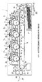
図2はカラー電子写真記録装置の概略構成を示す模式図である。カラー電子写真記録装置1には、4組の印刷機構P1、P2、P3、P4が記録媒体の挿入側から排出側へ順に並べられている。第1印刷機構P1、第2印刷機構P2、第3印刷機構P3、第4印刷機構P4は電子写真式LED(発光ダイオード)プリント機構で、それぞれ同一の構成を有する。
【0012】
第1印刷機構P1は、画像形成部2、画像データにしたがって後述する感光体を露光するLEDヘッド3および画像形成部2で形成されたトナー画像を記録媒体に転写する転写ローラ4で構成される。画像形成部2は軸5を中心に矢印a方向に回転する感光体6、感光体6の表面を一様に帯電させる帯電ローラ7それに現像部8から構成される。
【0013】
現像部8は現像ローラ8a、現像ブレード8b、スポンジローラ8c、トナータンク8d、トナー残量検出器8e(以後トナーセンサ8eと記する)から構成される。トナータンク8dから供給された非磁性1成分トナーは、スポンジローラ8cを経て、現像ブレード8bに達して現像ローラ8aに円周上に薄層化され、感光体6との接触面に達する。
【0014】
トナーセンサ8eは、第1印刷機構P1、第2印刷機構P2、第3印刷機構P3、第4印刷機構P4の各スポンジローラ8cの近傍に攪拌器と一体に設けてあり、例えば、特開平5−11610号に示すように、残留トナーの抵抗により攪拌レバーの回転周期が異なることを利用してトナー残量を検出している。
【0015】
トナーは薄層形成時に現像ローラ8aと現像ブレード8bに強く擦られて摩擦帯電される。本実施の形態では負極性に摩擦帯電される。スポンジローラ8cはトナーを適量現像ブレード8bに搬送する。なお、現像ローラ8aは半導電ゴム材で構成されている。トナーが無くなったときには、トナータンク8dを交換することによりトナーを新たに供給することができる。
【0016】
LEDヘッド3はLEDアレイとこのLEDアレイを駆動するドライブICを搭載した基板3aおよびLEDアレイの光を集光するセルフォックレンズアレイ3b等からなり、後述するインタフェース部から入力される画象データ信号に対応してLEDアレイを発光させ、感光体6の表面を露光し、感光体6の表面に静電潜像を形成する。
【0017】
静電潜像に現像ローラ8a円周上のトナーが静電気力によって付着して画像が形成される。感光体6と転写ローラ4の間には後述するキャリアベルト9が移動可能に配設されている。
【0018】
第1印刷機構P1の現像器8にはイエロー(Y)のトナーが収容され、第2印刷機構P2の現像器8にはマゼンタ(M)のトナーが収容され、第3印刷機構P3の現像器8にはシアン(C)のトナーが収容され、第4印刷機構P4の現像器8にはブラック(B)のトナーが収容されている。
【0019】
また、第1印刷機構P1のLEDヘッド3にはカラー画像信号のうちイエロー画像信号が入力され、第2印刷機構P2のLEDヘッド3にはカラー画像信号のうちマゼンタ画像信号が入力され、第3印刷機構P3のLEDヘッド3にはカラー画像信号のうちシアン画像信号が入力され、第4印刷機構P4のLEDヘッド3にはカラー画像信号のうちブラック画像信号が入力される。
【0020】
第1印刷機構P1の画像形成部2、第2印刷機構P2の画像形成部2、第3印刷機構P3の画像形成部2および第4印刷機構P4の画像形成部2はケース40に収納されており、カラー画像形成ユニット15を構成している。カラー画像形成ユニット15はカラー電子写真記録装置1から着脱できるように位置決め部材18、19により位置決めされている。
【0021】
キャリアベルト9は高抵抗の半導電性プラスチックフィルムからなり、継目なしのエンドレス状に形成されていて、駆動ローラ10、従動ローラ11および張設ローラ12に巻掛けられている。キャリアベルト9の抵抗値は、後述する記録媒体27がキャリアベルト9に静電吸着でき、かつこの記録媒体27がキャリアベルト9から離されたときにキャリアベルト9に残存する静電気が自然除電できるような範囲にあるものである。
【0022】
駆動ローラ10は後述するモータに接続され、このモータにより矢印b方向に回転する。張設ローラ12は矢印c方向に図示せぬバネにより付勢されていて、これにより常にキャリアベルト9が張設されている。キャリアベルト9の上面部9aは各印刷機構P1、P2、P3、P4の感光体6と転写ローラ4との間に掛け渡されている。
【0023】
キャリアベルト9を間に挟んで従動ローラ11側にクリーニングブレード14が押し付けられている。クリーニングブレード14は可撓性のゴムやプラスチック材から構成されており、先端がキャリアベルト9に圧接され、キャリアベルト9の表面上に付着している残留トナーを廃トナータンク15に削り落すようになっている。なお、本実施の形態では感光体6と転写ローラ4はキャリアベルト9に接触させる。
【0024】
カラー電子写真記録装置1の右下側には給紙機構20が設けられている。給紙機構20は用紙収容カセットとホッピング機構とレジストローラ30、31からなる。用紙収容カセットは記録媒体収容箱21、押し上げ板22と押圧手段23とからなる。ホッピング機構は弁別手段24、バネ25と給紙ローラ26とからなり、ホッピング機構により記録媒体27がガイド28、29に案内されて、一対のレジストローラ30、31に達するようになっている。
【0025】
レジストローラ30、31と第1印刷機構P1との間で、キャリアベルト9の上方には帯電器32が設けられている。帯電器32は給紙機構20によって送られてきた記録媒体27を帯電してキャリアベルト9の上面に静電吸着させるものである。帯電器32の手前側には記録媒体27の先端を検出するフォトインタラプタ60が設けてある。
【0026】
従動ローラ11側のキャリアベルト9を介した上方には除電器33が設けられている。除電器33はキャリアベルト9に吸着されて送られてきた記録媒体27を除電し、その吸着状態を解除して、キャリアベルト9から分離しやすくするものである。除電器33の左方には、記録媒体27の後端を検出するフォトインタラプタ61が設けてある。
【0027】
除電器33の左方には、ガイド34および定着器35が設けられている。定着器35はキャリアベルト9により搬送されて、トナー画像が転写された記録媒体27にトナー画像を定着するもので、記録媒体27上のトナーを加熱するヒートローラ36と、ヒートローラ36とともに記録媒体27を加圧する加圧ローラ37を有する。定着器35の左方は、排出口38になっており、その外側には排出スタッカ39が設けられている。排出スタッカ39には印刷済みの記録媒体27が排出される。
【0028】
図1は第1の実施の形態を示す制御ブロック図である。符号Y、M、C、Bは第1印刷機構P1、第2印刷機構P2、第3印刷機構P3、第4印刷機構P4の各印刷機構に対応している。制御回路41はマイクロプロセッサ41a(以後MPU41aと記する)とメモリ41bとを有し、メモリ41bに格納された電源テーブル41c、設定値格納部41d等を参照してカラー電子写真記録装置1全体の動作を制御する。メモリ41bは具体的にはROMにより構成される。
【0029】
MPU41には、印刷機構P1〜P4の各現像器8のスポンジローラ8cに電力を供給するが接続されている。SPバイアス電源42Y,42M,42C,42Bは、図3に示すように、空回転時にはトナーセンサ8eの出力値Qに応じてスポンジローラ8cに印加する電圧が異なるように切替自在であり、印刷時にはこの内、V2(42Y),V2(42M),V2(42C),V2(42B)の電圧を各現像器8のスポンジローラ8cに印加する。
【0030】
即ち、トナーセンサ8eの出力値Qが第1のトナー残量としての閾値M以上の場合にはV1(42Y),V1(42M),V1(42C),V1(42B)の電圧を各現像器8のスポンジローラ8cに印加し、トナーセンサ8eの出力値Qが第2のトナー残量としての閾値m以下の場合にはV3(42Y),V3(42M),V3(42C),V3(42B)の電圧を各現像器8のスポンジローラ8cに印加する。
【0031】
SPバイアス電源の電圧(絶対値)の関係はイエローをもって表すとV3<V2<V1であり、M,C,B共に同じである。
【0032】
閾値Mはトナーカートリッジを交換して現像部にトナーを補給したときを検出する値であり、閾値mは現像部のトナーがエンドに近いことを示すトナーニアエンドを検出する値であり、共に実験により決められる値である。
【0033】
また、MPU41には、印刷機構P1〜P4の各現像器8の現像ローラ8aに電力を供給するDBバイアス電源43Y,43M,43C,43Bが接続されている。DBバイアス電源43Y,43M,43C,43Bは、図3に示すように、空回転時にはトナーセンサ8eの出力値Qに応じて現像ローラ8aに印加する電圧が異なるように切替自在であり、印刷時にはこの内、V2(43Y),V2(43M),V2(43C),V2(43B)の電圧を各現像器8の現像ローラ8aに印加する。
【0034】
即ち、トナーセンサ8eの出力値Qが予め決められた閾値M以上の場合にはV1(43Y),V1(43M),V1(43C),V1(43B)の電圧を各現像器8の現像ローラ8aに印加し、トナーセンサ8eの出力値Qが予め決められた閾値m以下の場合にはV3(43Y),V3(43M),V3(43C),V3(43B)の電圧を各現像器8の現像ローラ8aに印加する。
【0035】
DBバイアス電源の電圧(絶対値)の関係はイエローをもって表すとV3<V2<V1であり、M,C,B共に同じである。
【0036】
さらに、SPバイアス電源とDBバイアス電源との電圧(絶対値)関係にはV3(42Y)≧V3(43Y)の関係があり、M,C,B共に同じである。
【0037】
また、MPU41にはトナーセンサ8eが接続されており、設定値格納部41dから閾値M、mを読み出し、電源テーブル41cを参照して空回転時のSPバイアス電源及びDBバイアス電源の切替を制御している。
【0038】
また、MPU41には、印刷機構P1〜P4の各帯電ローラ7に電力を供給する帯電用電源44Y、44M、44C、44Bと、各転写ローラ4を帯電させる電力を供給する転写用電源45Y、45M、45C、45Bとが、それぞれ接続されており、MPU41は電源テーブル41cを参照して帯電用電源44Y、44M、44C、44B及び転写用電源45Y、45M、45C、45Bを制御している。
【0039】
また、MPU41には、吸着帯電器32へ帯電用電力を供給する帯電用電源46、除電器33へ除電用の高圧電力を供給する除電用電源47が接続されている。以上の各電源は、MPU41の指示によりオン/オフ制御される。
【0040】
さらにMPU41には、印刷機構P1〜P4にそれぞれ対応する印刷制御回路48Y、48M、48C、48Bが接続されている。これら各印刷制御回路48Y、48M、48C、48Bは、画像メモリ49Y、49M、49C、49Bから画像データを入力し、これらのデータをMPU41からの指示により、LEDヘッド3へ出力し、LEDの露光時間を制御し、感光体6表面に静電潜像を形成する制御を行う。画像メモリ49Y、49M、49C、49BはRAMにより構成される。
【0041】
インタフェース部50は、外部装置、例えばホストコンピュータから送信されてきた画像データを色別に分解して、イエローの画像データは画像メモリ49Yへ、マゼンタの画像データは画像メモリ49Mへ、シアンの画像データは画像メモリ49Cへ、ブラックの画像データは画像メモリ49Bへ、それぞれ格納する。
【0042】
定着器ドライバ51は、定着器35内のヒートローラ36の温度を一定に保つように、ヒートローラ36内の図示しないヒータを駆動する。モータ駆動回路52は、給紙ローラ26を回転させるモータ53と、レジストローラ30,31、印刷機構P1〜P4の感光体6、帯電ローラ7、現像ローラ8a、スポンジローラ8c、転写ローラ4、駆動ローラ10およびヒートローラ36を回転するモータ54を駆動する。モータ54で回転される各ローラは、図示せぬギヤあるいはベルトにより連結されている。センサレシーバドライバ55は、フォトインタラプタ60、61を駆動し、それらの出力波形を受信して、MPU41へ送る。
【0043】
タイミングジェネレータ64はプログラマブルカウンタ等から構成されており、後述するクロックCL、スタート信号St、ライン信号Ls、リード信号RD、切替ラッチクリア信号Cr等のパルス信号を発生させるもので、必要に応じて図1の各回路へ送られる。
【0044】
アドレス切替信号発生回路65はタイミングジェネレータ64からリード信号RDおよび切替ラッチクリア信号Crを受けて周期的なアドレス切替信号Zmを出力するもので、その周期はMPU41によって設定されるデータDによって決まる。
【0045】
次に第1の実施の形態の動作について説明する。先ず、カラー電子写真記録装置1の電源68がオンされると、MPU41は所定の初期設定を実行した後、定着ドライバ51を駆動して、定着器35内のヒートローラ36を所定温度になるまでウォーミングアップする。MPU41は、ヒートローラ36が常に一定温度に保たれるように制御している。
【0046】
ヒートローラ36が所定温度になると、次にMPU41は、モータ駆動回路52を介して、モータ54を駆動し、レジストローラ30,31、印刷機構P1〜P4の感光体6、帯電ローラ7、現像ローラ8a、スポンジローラ8c、転写ローラ4、駆動ローラ10およびヒートローラ36を回転させる。キャリアベルト9は駆動ローラ10の回転により矢印d方向に回転し、ベルト表面のクリーニングを行う。
【0047】
このとき、MPU41は感光体6、帯電ローラ7、現像ローラ8a、スポンジローラ8c、転写ローラ4に印刷時と同じ電圧を印加する。また、MPU41は各現像器8のトナーセンサ8eを通じて各現像器8のトナー残量を検知しており、トナーセンサ8eの出力Qが閾値M以上の場合には、電源テーブル41cを参照してスポンジローラ8c、各現像器8の現像ローラ8aにそれぞれ印加するSPバイアス電源及びDBバイアス電源としてV1(42Y),V1(42M),V1(42C),V1(42B)とV1(43Y),V1(43M),V1(43C),V1(43B)とに切り替えて印加し、スポンジローラ8cから現像ローラ8aに供給されるトナーに印刷時に必要な電荷を帯電させる。
【0048】
また、トナーセンサ8eの出力Qが閾値m以下の場合には、電源テーブル41cを参照して現像ローラ8a、スポンジローラ8cにそれぞれ印加するSPバイアス電源及びDBバイアス電源としてV3(42Y),V3(42M),V3(42C),V3(42B)とV3(43Y),V3(43M),V3(43C),V3(43B)とに切り替えて印加し、スポンジローラ8cから現像ローラ8aに供給されるトナーが印刷時に必要な電荷以上に帯電しないようにする。
【0049】
キャリアベルト9が1周分より少し長く送られた時点で、モータ54を停止し、キャリアベルト9の移動を停止する。これによりキャリアベルト9の表面上に付着している残留トナーやゴミがクリーニングブレード13によって廃トナータンク14へ削り落される。
【0050】
また、各現像器8のトナーは印刷に適宜な帯電電圧を保持している。
【0051】
以上によりカラー電子写真記録装置1はインタフェース部50を介して外部装置から画像データが送られて来るのを待つ。
【0052】
インタフェース部50を介して外部装置、すなわち、ホストコンピュータから送られてきた画像データを受信すると、MPU41は、インタフェース部50および各画像メモリ49Y、49M、49C、49Bに指示を出す。この指示により、インタフェース部50は、受信した画像データ信号を色別に分解し、各画像メモリ49Y、49M、49C、49Bに記憶させる。すなわち、イエローの画像データは画像メモリ49Yに、マゼンタの画像データは画像メモリ49Mに、シアンの画像データは画像メモリ49Cに、ブラックの画像データは画像メモリ49Bに、それぞれ記憶される。このように各画像メモリ49Y、49M、49C、49Bには、それぞれ記録媒体27上に印刷される1ページ分の各色の画像データが記憶される。
【0053】
この状態から画像データを印刷する動作について説明する。MPU41はモータ駆動回路52を介して、モータ53を駆動し、給紙ローラ26を回転させる。給紙ローラ26の回転により用紙収納箱21の記録媒体27が1枚だけ繰出されてガイド28、29へ送られ、記録媒体27の先端がレジストローラ30、31に到達する距離より若干長く記録媒体27を搬送させるべくモータ駆動回路52を制御する。これにより記録媒体27は、先端をレジストローラ30、31のローラの間に押し当てて若干撓んだ状態になり、この撓みにより記録媒体27のスキューが修正される。
【0054】
次にMPU41は、モータ駆動回路52を介してモータ54を駆動し、レジストローラ30、31、各印刷機構P1、P2、P3、P4の感光体6、帯電ローラ7、現像ローラ8a、スポンジローラ8c、転写ローラ4、駆動ローラ10および定着器35のヒートローラ36をそれぞれ回転させる。これと同時に、各印刷機構P1、P2、P3、P4の帯電ローラ7および現像ローラ8a、スポンジローラ8cに電圧を供給するために、MPU41はそれぞれ帯電用電源44Y、44M、44C、44B、DBバイアス電源43Y、43M、43C、43B、SPバイアス電源42Y,42M,42C,42Bをオンする。
【0055】
このとき、SPバイアス電源42Y,42M,42C,42BはV2(42Y),V2(42M),V2(42C),V2(42B)の電圧を各現像器8の現像ローラ8aに印加し、DBバイアス電源43Y、43M、43C、43BはV2(43Y),V2(43M),V2(43C),V2(43B)の電圧を各現像器8の現像ローラ8aに印加する。
【0056】
以上により、各印刷機構P1、P2、P3、P4の感光体6表面は帯電ローラ7を介して、均一に帯電され、各印刷機構P1、P2、P3、P4のスポンジローラ8cおよび現像ローラ8aは所定の高電圧に帯電される。
【0057】
次にMPU41は、イエローの画像データが記憶している画像メモリ49Yに指令を出し、1ライン分のイエローの画像データを画像メモリ49Yから、第1印刷機構P1の印刷制御回路48Yへ送信する。第1印刷機構P1の印刷制御回路48Yは、MPU41からの指令により、画像メモリ49Yから送られてきた画像データを、第1印刷機構P1のLEDヘッド3へ送信できる形に変えて、このLEDヘッド3へ送信する。LEDヘッド3は、送られてきた画像データに対応するLEDを点灯させ、帯電した感光体6表面に画像データに応じた1ライン分の静電潜像を形成する。このようにして、1ライン毎に画像メモリ49Yから送られてくるイエローの画像データは、次々に感光体6表面に静電潜像化され、副走査方向の長さ分のイエローの画像データが潜像化されて露光が終了する。
【0058】
静電潜像が形成された感光体6表面には、帯電したイエロートナーが現像ローラ8aにより付着される。感光体6の回転により、静電潜像は次々にイエローのトナーにより現像化される。
【0059】
記録媒体27の先端が感光体6と転写ローラ4の間に到達した時点で、MPU41は、第1印刷機構P1の転写用電源45Yをオンする。これにより感光体6表面のトナー画像は、転写ローラ4により電気的に記録媒体27上に転写される。感光体6の回転により、トナー画像は次々に記録媒体27上に転写され、1ページ分のイエロー画像が記録媒体27に転写される。以上により、第1印刷機構P1による記録媒体27へのイエローのトナー画像の転写が終了する。そして、記録媒体27の後端が感光体6と転写ローラ4の間に到達した時点で、MPU41は、第1印刷機構P1の転写用電源45Y、帯電用電源44Y、SPバイアス電源42Y、DBバイアス電源43Yをオフにする。
【0060】
キャリアベルト9は引続き移動しており、記録媒体27は、第1印刷機構P1から第2印刷機構P2、第3印刷機構P3、第4印刷機構P4へ移り、各印刷機構において上述した動作と同様に、マゼンタ、イエロー、ブラックのトナー画像の転写が行われる。
【0061】
以上のように、各色のトナー画像が記録媒体27上に重ねて転写される。その後記録媒体27は、キャリアベルト9により除電気33へ送られ、ここでMPU41は除電用電源47をオンし、記録媒体27を除電する。これにより記録媒体27は、キャリアベルト9から離れ易くなり、従動ローラ11の上部でキャリアベルト9から離れ、用紙ガイド34により定着器35へ案内される。記録媒体27が除電器33から離れた時点で、MPU41は除電用電源をオフする。
【0062】
定着器35では、既に定着可能な温度に達しているヒートローラ36と、これに圧接する加圧ローラ37により、トナー画像が記録媒体27に定着される。定着が終了すると、記録媒体27は排出スタッカ39へ排出される。この排出はフォトインタラプタ61が記録媒体27の後端を検出することによりMPU41は知ることができる。
【0063】
排出が終了すると、MPU41はモータ駆動回路52を介してモータ54を停止する。以上のようにして印刷動作が実行される。
【0064】
本実施の形態では、現像部のトナー残量検出器が検出するトナー残量に応じてスポンジローラ、現像ローラに印加する電圧を変えるようにしたが、電圧に代えて空回転時の回転時間、あるいは回転速度を変えるようにしてもよい。
【0065】
第1の実施の形態よれば、現像部のトナー残量が所定量以上ある場合には空回転中、スポンジローラ、現像ローラにそれぞれ印刷中に印加する電圧より高い電圧を印加するようにしたことにより、トナーカートリッジが交換されて現像部に新規のトナーが補充されたり、感光体が寿命に達して現像装置が交換されたりした場合にトナーの帯電量不足を防止できるので、印刷時に印刷用紙に転写されるトナーの濃度を均一にすることができる。
【0066】
また、現像部のトナー残量が所定量以下の場合には空回転中、スポンジローラ、現像ローラにそれぞれ印刷中に印加する電圧より低い電圧を印加するようにしたことにより、現像ローラ上のトナーの過帯電を防止するので、印刷時に印刷用紙に転写されるトナーの濃度を均一にすることができる。
【0067】
第2の実施の形態
第1の実施の形態では現像部のトナー量に応じて空回転時の現像ローラ8a及びスポンジローラ8cへの印加電圧を印刷時の印加電圧より高く、あるいは低くしたが、第2の実施の形態では空回転時、さらに帯電ローラ7の印加電圧を調整する。
【0068】
即ち、印刷時、帯電ローラ7は感光体6の表面を−800V程度に帯電させており、この電位は現像ローラ8aの帯電電位の3倍以上である。従って、空回転時、現像ローラ8aに付着しているトナーは感光体6との接触部を通る度に高電位の負電圧を帯びながら回転しており、トナーの負電位を必要以上に上げることになる。
【0069】
そこで、空回転時、感光体6の表面電位を現像ローラ8aの印加電圧と同等程度、即ち、イエローをもって帯電用電源44YとDBバイアス電源42Yとの電圧(絶対値)の関係を表すと、44Y≧V3(43Y),44Y≧V2(43Y),44Y≧V1(43Y)であり、M,C,B共に同じである。
【0070】
第2の実施の形態によれば、空回転時、感光体の表面電位を現像ローラの印加電圧と同等まで下げるように帯電ローラへの印加電圧を下げるようにしたことにより、現像ローラ上のトナーの過帯電を防止するので、印刷時に印刷用紙に転写されるトナーの濃度を均一にすることができる。
【0071】
第3の実施の形態
第1及び第2の実施の形態では空回転時に現像ローラ、スポンジローラ、帯電ローラに印加する電圧を操作したが、電圧は印刷時に印加する電圧にし、通常の空回転時間より長時間、空回転するようにして充分に摩擦による帯電量を蓄積させるようにしてもよい。
【0072】
そこで、第3の実施の形態では画像装置を新規なものに交換した場合には通常の空回転時間より長時間、空回転するようにして充分に摩擦による帯電量を蓄積させるようにする。
【0073】
装置の構成は、第1及び第2の実施の形態に示したものと同じなので省略し、本実施の形態に係わる制御ブロックについて図4を参照して説明する。
【0074】
図4は第3の実施の形態による制御ブロック図である。印刷処理部410はモータ53を駆動して、図2に示した用紙収納箱21から記録媒体27を1枚繰り出し、モータ54、LEDヘッド3を駆動し、画像メモリ49から読み出した画像データを感光体6の表面に静電潜像化したのち記録媒体27にトナー画像として転写し、定着器35で定着して排出スタッカ39へ排出する。そして印刷する度に装置の消耗度を示す消耗値を格納する消耗値格納部411の内容をインクリメントする。
【0075】
寿命判定処理部412は、寿命判定値格納部413に格納されている寿命判定値(例えば感光体6の寿命までの総回転数)と消耗値格納部411の内容とを比較して消耗値が寿命判定値を越えたとき寿命に達したと判定して参照値格納部414の内容を「1」とするとともに表示部420に「画像装置交換」のメッセージを表示し、消耗値が寿命判定値に達しない場合には寿命に達しないと判断して参照値格納部414の内容を「0」とする。
【0076】
空回転処理部415は参照値が「0」の場合には第1の回転時間格納部416に格納されている第1の回転時間に基づきモータ54を駆動して空回転処理を行い、「1」の場合には第2の回転時間格納部417に格納されている第2の回転時間に基づきモータ54を駆動して空回転処理を行う。
【0077】
クリア処理部418はクリアキー421の押下に基づいて参照値格納部414の内容を「0」にする。
【0078】
具体的には、印刷処理部410、寿命判定処理部412、空回転処理部415、クリア処理部418をMPU41aにより構成し、消耗値格納部411、寿命判定値格納部413、参照値格納部414、第1の回転時間格納部416、第2の回転時間格納部417をメモリ41bで構成する。
【0079】
図5は現像装置交換時の空回転時間と画像濃度との関係図である。横軸を空回転時間とし、縦軸を画像濃度として画像濃度が安定するまでをプロットしたものであり、関係図から分かる通り、10分以上空回転処理すれば画像濃度は1.2で安定する。従って、上述した第2の空回転時間は10分以上である。
【0080】
画像濃度とは対象とする画像に光を照射し、画像からの反射率Rの逆数を自然対数で表した値Dであり、反射率Rが1(反射率100%)であれば画像濃度D=0となり、反射率Rが0(反射率0%)であれば画像濃度D=∞となる。例えば、反射率R=0.1であれば、画像濃度D=1であり、反射率=0.05であれば、画像濃度D=1.3である。
【0081】
図6は空回転処理を示すフローチャートである。電源スイッチをオンにすると、リセットされたMPU41aはステップS1で装置を初期設定する。このとき参照値格納部414の参照値は「0」にセットされる。
【0082】
ステップS2でMPU41aは、第1の回転時間格納部416から第1の回転時間を読み出して通常の空回転処理を行う。
【0083】
ステップS3でMPU41aは、参照値格納部414の参照値を参照し、「1」の場合には現像装置が交換されたと判定してステップS4に分岐し、否の場合にはステップS5に分岐する。
【0084】
ステップS4でMPU41aは、第2の回転時間格納部417から第2の回転時間を読み出して10分以上、空回転処理を行う。
【0085】
ステップS5でMPU41aは印刷データの有無をセンスしており、印刷データが有る場合にはステップS6に分岐する。
【0086】
ステップS6でMPU41aは用紙収納箱21から記録媒体27を1枚繰り出して印刷し、画像メモリ49から画像データを読み出して印刷するとともに消耗値格納部411の内容(感光体6の累積回転数)をインクリメントする。
【0087】
ステップS7でMPU41aは消耗値格納部411の内容と参照値格納部414の内容とを比較して現像装置が寿命に達したか否かをチェックし、現像装置が寿命に達した場合にはステップS8に分岐し、否の場合にはステップS5に分岐する。
【0088】
ステップS8でMPU41aは参照値格納部414の参照値を「1」にセットするとともに表示部420に「現像装置交換」のメッセージを表示する。
【0089】
ステップS9でMPU41aは画像メモリ49に印刷データが未だ残っているか否かをチェックして印刷データが未だ残っている場合にはステップS5に分岐し、否の場合にはステップS10に分岐する。
【0090】
ステップS10でMPU41aは電源スイッチがオフにされたか否かをチェックし、電源スイッチがオフにされた場合には処理を終了し、否の場合にはステップS5に分岐する。
【0091】
オペレータは「現像装置交換」のメッセージを見て、現像装置交換のために電源スイッチをオフにし、現像装置を交換したのち再度、電源スイッチをオンにする。そしてクリアキー421を押下して参照値格納部414の参照値を「0」するので、その場合にはステップS4で10分以上、空回転処理が行なわれ、その後ステップS5に移って印刷処理待ちになる。
【0092】
尚、本実施の形態では、現像装置を交換した場合について説明したが、トナーカートリッジを交換してトナーを追加した場合にもトナーセンサ8eの出力値Qと閾値とを比較して出力値Qが閾値以上の場合には第2の回転時間を読み出して10分以上、空回転処理を行い、出力値Qが閾値未満の場合には第1の回転時間を読み出して空回転処理を行うようにすれば適用できる。
【0093】
また、本実施の形態では、空回転時間を長くするとしたが、回転速度を上げてもよい。この場合、回転時間を短縮できる。
【0094】
第3の実施の形態によれば、感光体が寿命に達して現像装置を交換した場合には通常の空回転時間より時間空回転するようにして充分に摩擦による帯電量を蓄積させるようにしたので、画像濃度の低下を防止し、交換前と同じ画像濃度を保持することができる。
【0095】
第1〜第3実施の形態ではカラー電子写真記録装置を例にとって説明したが、本発明は単色の電子写真記録装置にも適用可能である。
【0096】
【発明の効果】
本発明は、以上説明したように構成されているので以下に記載される効果を奏する。
【0097】
空回転を行うときにトナー残量検出器が検出するトナー残量が現像部に新規のトナーが供給されたことを示す第1のトナー残量以上であるとき、現像部に印加する電圧を印刷時に印加する電圧より絶対値で高くするようにしたことにより、トナーカートリッジが交換されて現像部に新規のトナーが補充されたり、感光体が寿命に達して現像装置が交換されたりした場合にトナーの帯電量不足を防止できるので、印刷時に印刷用紙に転写されるトナーの濃度を均一にすることができる。
【図面の簡単な説明】
【図1】第1の実施の形態を示す制御ブロック図である。
【図2】カラー電子写真記録装置の概略構成を示す模式図である。
【図3】トナーセンサ出力値とSP及びDBバイアス電圧との関係を示す説明図である。
【図4】第3の実施の形態による制御ブロック図である。
【図5】現像装置交換時の空回転時間と画像濃度との関係図である。
【図6】第3の実施の形態による空回転処理を示すフローチャートである。
【符号の説明】
2 画像形成部
7 帯電ローラ
8a 現像ローラ
8c スポンジローラ
8e トナーセンサ
41 制御回路
41a MPU
41b メモリ[0001]
BACKGROUND OF THE INVENTION
The present invention relates to an image forming apparatus mounted on an electrophotographic recording apparatus, a copying machine or the like.
[0002]
[Prior art]
Conventionally, in an electrophotographic recording apparatus, for example, a color electrophotographic recording apparatus, when the power switch is turned on and the surface of the fixing roller reaches a predetermined temperature, a carrier belt is used to clean the carrier belt that conveys printing paper. The photosensitive member, the charging roller, the developing roller, etc. of the image forming apparatus are rotated by one or more revolutions, are rotated by idling by applying the voltage under the same conditions as in printing, and the printing standby state is entered. By idling, the toner in the developing portion is precharged by frictional charging.
[0003]
[Problems to be solved by the invention]
In the conventional image forming apparatus, when the toner cartridge is replaced or when the developing device is replaced when the photosensitive member reaches the end of its life, it is a new uncharged toner. As a result, there is a problem that good printing results cannot be obtained.
[0004]
SUMMARY An advantage of some aspects of the invention is that it provides an image forming apparatus capable of obtaining good printing results even when a toner cartridge is replaced or a developing device is replaced.
[0005]
[Means for Solving the Problems]
In order to achieve the above object, in the image forming apparatus of the present invention,A toner remaining amount detector for detecting the remaining amount of toner in the developing unit has a toner remaining amount detected by the remaining toner amount detector when performing idling, indicating that new toner has been supplied to the developing unit. When the amount of remaining toner is 1 or more, the voltage applied to the developing unit is made higher in absolute value than the voltage applied during printing.Is.
[0010]
DETAILED DESCRIPTION OF THE INVENTION
Embodiments of the present invention will be described with reference to the drawings. In addition, the same code | symbol is attached | subjected to the element common to each drawing.
[0011]
First embodiment
FIG. 2 is a schematic diagram showing a schematic configuration of the color electrophotographic recording apparatus. In the color
[0012]
The first printing mechanism P1 includes an
[0013]
The developing
[0014]
The toner sensor 8e is integrally provided with a stirrer in the vicinity of the
[0015]
The toner is frictionally charged by being strongly rubbed against the developing
[0016]
The
[0017]
The toner on the circumference of the developing
[0018]
The developing
[0019]
The yellow image signal of the color image signal is input to the
[0020]
The
[0021]
The carrier belt 9 is made of a high-resistance semiconductive plastic film, is formed in a seamless endless shape, and is wound around the
[0022]
The
[0023]
A
[0024]
A
[0025]
A charger 32 is provided above the carrier belt 9 between the
[0026]
A
[0027]
A
[0028]
FIG. 1 is a control block diagram showing the first embodiment. Reference symbols Y, M, C, and B correspond to the printing mechanisms of the first printing mechanism P1, the second printing mechanism P2, the third printing mechanism P3, and the fourth printing mechanism P4. The
[0029]
The
[0030]
That is, when the output value Q of the toner sensor 8e is equal to or greater than the threshold M as the first toner remaining amount, the voltages of V1 (42Y), V1 (42M), V1 (42C), and V1 (42B) are applied to the developing devices. 8 when the output value Q of the toner sensor 8e is equal to or less than the threshold value m as the second toner remaining amount, V3 (42Y), V3 (42M), V3 (42C), V3 (42B) ) Is applied to the
[0031]
The relationship of the SP bias power supply voltage (absolute value) is represented by V3 <V2 <V1 in yellow, and M, C, and B are the same.
[0032]
The threshold value M is a value for detecting when the toner cartridge is replaced and the developing unit is replenished with toner. The threshold value m is a value for detecting the toner near end indicating that the toner in the developing unit is close to the end. It is a value that can be determined.
[0033]
The
[0034]
That is, when the output value Q of the toner sensor 8e is equal to or greater than a predetermined threshold value M, the voltages of V1 (43Y), V1 (43M), V1 (43C), and V1 (43B) are set to the developing rollers of the developing
[0035]
The relationship of the voltage (absolute value) of the DB bias power supply is represented by yellow as V3 <V2 <V1, and M, C, and B are the same.
[0036]
Further, the voltage (absolute value) relationship between the SP bias power source and the DB bias power source has a relationship of V3 (42Y) ≧ V3 (43Y), and M, C, and B are the same.
[0037]
Further, the toner sensor 8e is connected to the
[0038]
The
[0039]
The
[0040]
Further, the
[0041]
The
[0042]
The fixing
[0043]
The
[0044]
The address switching
[0045]
Next, the operation of the first embodiment will be described. First, when the
[0046]
When the
[0047]
At this time, the
[0048]
When the output Q of the toner sensor 8e is equal to or less than the threshold value m, V3 (42Y) and V3 (V3 (42Y), V3 (SP bias power and DB bias power applied to the developing
[0049]
When the carrier belt 9 is fed a little longer than one round, the
[0050]
Further, the toner of each developing
[0051]
As described above, the color
[0052]
When the image data sent from the external device, that is, the host computer is received via the
[0053]
An operation for printing image data from this state will be described. The
[0054]
Next, the
[0055]
At this time, the SP bias
[0056]
As described above, the surface of the
[0057]
Next, the
[0058]
The charged yellow toner is attached to the surface of the
[0059]
When the leading edge of the
[0060]
The carrier belt 9 continues to move, and the
[0061]
As described above, the toner images of the respective colors are transferred onto the
[0062]
In the fixing
[0063]
When the discharge is completed, the
[0064]
In the present embodiment, the voltage applied to the sponge roller and the developing roller is changed according to the toner remaining amount detected by the toner remaining amount detector of the developing unit, but the rotation time during idling instead of the voltage, Alternatively, the rotation speed may be changed.
[0065]
According to the first embodiment, when the remaining amount of toner in the developing unit is a predetermined amount or more, a voltage higher than the voltage applied during printing is applied to each of the sponge roller and the developing roller during idling. Therefore, when the toner cartridge is replaced and new toner is replenished to the developing unit, or when the developing device is replaced when the photosensitive member reaches the end of its life, it is possible to prevent the toner from being insufficiently charged. The density of the transferred toner can be made uniform.
[0066]
In addition, when the remaining amount of toner in the developing unit is less than a predetermined amount, the toner on the developing roller is applied by applying a voltage lower than the voltage applied during printing to the sponge roller and the developing roller during idling. Therefore, it is possible to make the density of the toner transferred to the printing paper uniform during printing.
[0067]
Second embodiment
In the first embodiment, the voltage applied to the developing
[0068]
That is, at the time of printing, the charging
[0069]
Therefore, when the idling state, the surface potential of the
[0070]
According to the second embodiment, the toner on the developing roller is reduced by reducing the applied voltage to the charging roller so that the surface potential of the photosensitive member is lowered to the same as the applied voltage of the developing roller during idling. Therefore, it is possible to make the density of the toner transferred to the printing paper uniform during printing.
[0071]
Third embodiment
In the first and second embodiments, the voltage applied to the developing roller, the sponge roller, and the charging roller during idling is operated. However, the voltage is set to the voltage to be applied during printing, and idling for a longer time than the normal idling time. In this way, the charging amount due to friction may be sufficiently accumulated.
[0072]
Therefore, in the third embodiment, when the image apparatus is replaced with a new one, the charge amount due to friction is sufficiently accumulated by idling for a longer time than the normal idling time.
[0073]
Since the configuration of the apparatus is the same as that shown in the first and second embodiments, a description thereof will be omitted, and a control block according to this embodiment will be described with reference to FIG.
[0074]
FIG. 4 is a control block diagram according to the third embodiment. The
[0075]
The life
[0076]
When the reference value is “0”, the idle
[0077]
The
[0078]
Specifically, the
[0079]
FIG. 5 is a graph showing the relationship between the idling time and the image density when the developing device is replaced. The horizontal axis is the idling time, the vertical axis is the image density, and the plot until the image density is stabilized is plotted. As can be seen from the relationship diagram, the image density is stabilized at 1.2 when idling for 10 minutes or more. . Therefore, the second idling time described above is 10 minutes or more.
[0080]
The image density is a value D obtained by irradiating a target image with light and expressing the reciprocal of the reflectance R from the image as a natural logarithm. If the reflectance R is 1 (reflectance 100%), the image density D If the reflectance R is 0 (
[0081]
FIG. 6 is a flowchart showing the idling process. When the power switch is turned on, the
[0082]
In step S2, the
[0083]
In step S3, the
[0084]
In step S4, the
[0085]
In step S5, the
[0086]
In step S6, the
[0087]
In step S7, the
[0088]
In step S <b> 8, the
[0089]
In step S9, the
[0090]
In step S10, the
[0091]
The operator sees the message “Replace development device”, turns off the power switch for replacement of the development device, replaces the development device, and then turns on the power switch again. Then, the
[0092]
In this embodiment, the case where the developing device is replaced has been described. However, even when the toner cartridge is replaced and toner is added, the output value Q of the toner sensor 8e is compared with the threshold value to obtain the output value Q. If the output value Q is less than the threshold value, the first rotation time is read and the idling process is performed when the second rotation time is read out and the second rotation time is read out for 10 minutes or more. If applicable.
[0093]
In the present embodiment, the idling time is increased, but the rotation speed may be increased. In this case, the rotation time can be shortened.
[0094]
According to the third embodiment, when the photoconductor reaches the end of its life and the developing device is replaced, the charge amount due to friction is sufficiently accumulated by causing the photoconductor to idle for a time longer than the normal idling time. Therefore, it is possible to prevent a decrease in image density and to maintain the same image density as before replacement.
[0095]
In the first to third embodiments, the color electrophotographic recording apparatus has been described as an example, but the present invention can also be applied to a monochrome electrophotographic recording apparatus.
[0096]
【The invention's effect】
Since the present invention is configured as described above, the following effects can be obtained.
[0097]
When the remaining toner amount detected by the remaining toner detector when performing idling is equal to or higher than the first remaining toner amount indicating that new toner has been supplied to the developing unit, the voltage applied to the developing unit is printed. It was made higher in absolute value than the voltage applied sometimes.This prevents the toner from being insufficiently charged when the toner cartridge is replaced and new toner is replenished to the developing unit, or when the photoconductor reaches the end of its life and the developing device is replaced. The density of the toner transferred to the toner can be made uniform.
[Brief description of the drawings]
FIG. 1 is a control block diagram illustrating a first embodiment.
FIG. 2 is a schematic diagram showing a schematic configuration of a color electrophotographic recording apparatus.
FIG. 3 is an explanatory diagram showing a relationship between a toner sensor output value and SP and DB bias voltages;
FIG. 4 is a control block diagram according to a third embodiment.
FIG. 5 is a graph showing the relationship between the idling time and the image density when the developing device is replaced.
FIG. 6 is a flowchart showing idling processing according to the third embodiment.
[Explanation of symbols]
2 Image forming unit
7 Charging roller
8a Development roller
8c sponge roller
8e Toner sensor
41 Control circuit
41a MPU
41b memory
Claims (6)
前記現像部のトナー残量を検出するトナー残量検出器を有し、
前記空回転を行うときに前記トナー残量検出器が検出するトナー残量が前記現像部に新規のトナーが供給されたことを示す第1のトナー残量以上であるとき、前記現像部に印加する電圧を印刷時に印加する電圧より絶対値で高くすることを特徴とする画像形成装置。In an image forming apparatus that rotates idly with a photosensitive member while applying a voltage to a charging unit and a developing unit before printing,
A toner remaining amount detector for detecting the remaining amount of toner in the developing unit;
Applied to the developing unit when the remaining amount of toner detected by the remaining toner detector when performing the idling is greater than or equal to a first toner remaining amount indicating that new toner has been supplied to the developing unit. An image forming apparatus characterized in that the voltage to be applied is higher in absolute value than the voltage applied during printing.
前記空回転において前記キャリアベルトが1周以上送られることを特徴とする請求項1記載の画像形成装置。A carrier belt wound around a plurality of rollers and disposed to face the photoreceptor;
The image forming apparatus according to claim 1, wherein the carrier belt is fed one or more times during the idling.
Priority Applications (2)
| Application Number | Priority Date | Filing Date | Title |
|---|---|---|---|
| JP2001058220A JP4008202B2 (en) | 2001-03-02 | 2001-03-02 | Image forming apparatus |
| US10/087,058 US6763200B2 (en) | 2001-03-02 | 2002-02-28 | Image forming apparatus with toner replacement sensor |
Applications Claiming Priority (1)
| Application Number | Priority Date | Filing Date | Title |
|---|---|---|---|
| JP2001058220A JP4008202B2 (en) | 2001-03-02 | 2001-03-02 | Image forming apparatus |
Publications (3)
| Publication Number | Publication Date |
|---|---|
| JP2002258676A JP2002258676A (en) | 2002-09-11 |
| JP2002258676A5 JP2002258676A5 (en) | 2005-03-03 |
| JP4008202B2 true JP4008202B2 (en) | 2007-11-14 |
Family
ID=18917979
Family Applications (1)
| Application Number | Title | Priority Date | Filing Date |
|---|---|---|---|
| JP2001058220A Expired - Fee Related JP4008202B2 (en) | 2001-03-02 | 2001-03-02 | Image forming apparatus |
Country Status (2)
| Country | Link |
|---|---|
| US (1) | US6763200B2 (en) |
| JP (1) | JP4008202B2 (en) |
Cited By (1)
| Publication number | Priority date | Publication date | Assignee | Title |
|---|---|---|---|---|
| US11314181B2 (en) * | 2019-12-23 | 2022-04-26 | Kyocera Document Solutions Inc. | Image forming device |
Families Citing this family (13)
| Publication number | Priority date | Publication date | Assignee | Title |
|---|---|---|---|---|
| US20050036796A1 (en) * | 2003-08-15 | 2005-02-17 | Burchette Lynton R. | System and method for adjusting toner consumption |
| KR100636155B1 (en) * | 2004-07-27 | 2006-10-19 | 삼성전자주식회사 | Method of optimizing amount of the toner of electrophotogrphic printer |
| US7356272B2 (en) * | 2004-10-29 | 2008-04-08 | Seiko Epson Corporation | Image forming apparatus with developing roller that rotates during standby to ensure toner uniformity |
| JP4943241B2 (en) * | 2007-06-14 | 2012-05-30 | 株式会社リコー | Maintenance management system and image forming apparatus |
| JP2009003313A (en) * | 2007-06-25 | 2009-01-08 | Oki Data Corp | Image forming apparatus |
| JP4598049B2 (en) * | 2007-11-30 | 2010-12-15 | 株式会社沖データ | Image processing device |
| JP4981842B2 (en) * | 2009-04-20 | 2012-07-25 | 株式会社沖データ | Image forming apparatus |
| US8577236B2 (en) * | 2009-12-10 | 2013-11-05 | Xerox Corporation | Reducing reload image quality defects |
| US9110405B2 (en) * | 2010-12-20 | 2015-08-18 | Canon Finetech Inc. | Image forming apparatus having a developer install mode |
| US9075337B2 (en) * | 2012-04-03 | 2015-07-07 | Kabushiki Kaisha Toshiba | Image forming apparatus and method using electrophotographic two-component development |
| JP5984473B2 (en) | 2012-04-13 | 2016-09-06 | キヤノン株式会社 | Image forming apparatus |
| JP6204268B2 (en) * | 2014-05-29 | 2017-09-27 | 京セラドキュメントソリューションズ株式会社 | Image forming apparatus |
| US20220373942A1 (en) * | 2021-05-20 | 2022-11-24 | Zhuhai Pantum Electronics Co., Ltd. | Image forming apparatus and control method thereof, and electronic apparatus |
Family Cites Families (6)
| Publication number | Priority date | Publication date | Assignee | Title |
|---|---|---|---|---|
| US4777512A (en) * | 1985-12-11 | 1988-10-11 | Canon Kabushiki Kaisha | Image forming apparatus with delay during toner replenishment |
| JPH04348369A (en) * | 1991-02-08 | 1992-12-03 | Fuji Xerox Co Ltd | No-toner detection controlling method for developing device |
| JPH09179458A (en) * | 1995-12-25 | 1997-07-11 | Minolta Co Ltd | Image forming device |
| KR100202410B1 (en) * | 1996-08-24 | 1999-06-15 | 윤종용 | Agitator driving method |
| US6226481B1 (en) * | 1998-12-07 | 2001-05-01 | Ricoh Company, Ltd. | Image forming apparatus with control over developing unit during an idle running of an intermediate image transfer body |
| US6559210B2 (en) * | 2000-02-28 | 2003-05-06 | Canon Kabushiki Kaisha | Charging member and electrophotographic apparatus |
-
2001
- 2001-03-02 JP JP2001058220A patent/JP4008202B2/en not_active Expired - Fee Related
-
2002
- 2002-02-28 US US10/087,058 patent/US6763200B2/en not_active Expired - Lifetime
Cited By (1)
| Publication number | Priority date | Publication date | Assignee | Title |
|---|---|---|---|---|
| US11314181B2 (en) * | 2019-12-23 | 2022-04-26 | Kyocera Document Solutions Inc. | Image forming device |
Also Published As
| Publication number | Publication date |
|---|---|
| US20020122673A1 (en) | 2002-09-05 |
| US6763200B2 (en) | 2004-07-13 |
| JP2002258676A (en) | 2002-09-11 |
Similar Documents
| Publication | Publication Date | Title |
|---|---|---|
| JP3385134B2 (en) | Electrophotographic recording device | |
| JP4008202B2 (en) | Image forming apparatus | |
| US7844200B2 (en) | Image forming apparatus with a pre-exposure light control feature | |
| JPH11231598A (en) | Color image recording device | |
| US20130141511A1 (en) | Image forming apparatus | |
| US8090278B2 (en) | Image forming apparatus having an image bearing body | |
| JP2002372882A (en) | Image recorder | |
| JP4551941B2 (en) | Image forming apparatus | |
| JP3566372B2 (en) | Image forming device | |
| US9250568B1 (en) | Image forming apparatus and image forming method | |
| CN100476622C (en) | Electrophotographic image forming apparatus | |
| US20050129421A1 (en) | Image forming apparatus | |
| JP2001215796A (en) | Image forming device | |
| JP2001075329A (en) | Color image forming device | |
| JP4164277B2 (en) | Image forming apparatus | |
| JP2008304823A (en) | Image forming apparatus | |
| JP2001235985A (en) | Image recorder | |
| JP2007304186A (en) | Image printing device, its control method and its program | |
| JP4008130B2 (en) | Fixing device control device and image recording device | |
| JP2013003415A (en) | Image forming apparatus and image forming method | |
| JP2006106232A (en) | Image forming apparatus and image forming method | |
| JP7318454B2 (en) | Image forming apparatus and image forming method | |
| JPH1063049A (en) | Printer | |
| JPH11327351A (en) | Controller for fixing unit | |
| JP2009181115A (en) | Image forming device |
Legal Events
| Date | Code | Title | Description |
|---|---|---|---|
| A521 | Request for written amendment filed |
Free format text: JAPANESE INTERMEDIATE CODE: A523 Effective date: 20040401 |
|
| A621 | Written request for application examination |
Free format text: JAPANESE INTERMEDIATE CODE: A621 Effective date: 20040401 |
|
| A977 | Report on retrieval |
Free format text: JAPANESE INTERMEDIATE CODE: A971007 Effective date: 20060927 |
|
| RD02 | Notification of acceptance of power of attorney |
Free format text: JAPANESE INTERMEDIATE CODE: A7422 Effective date: 20061025 |
|
| A131 | Notification of reasons for refusal |
Free format text: JAPANESE INTERMEDIATE CODE: A131 Effective date: 20061031 |
|
| A521 | Request for written amendment filed |
Free format text: JAPANESE INTERMEDIATE CODE: A523 Effective date: 20061226 |
|
| TRDD | Decision of grant or rejection written | ||
| A01 | Written decision to grant a patent or to grant a registration (utility model) |
Free format text: JAPANESE INTERMEDIATE CODE: A01 Effective date: 20070821 |
|
| A61 | First payment of annual fees (during grant procedure) |
Free format text: JAPANESE INTERMEDIATE CODE: A61 Effective date: 20070829 |
|
| FPAY | Renewal fee payment (event date is renewal date of database) |
Free format text: PAYMENT UNTIL: 20100907 Year of fee payment: 3 |
|
| R150 | Certificate of patent or registration of utility model |
Ref document number: 4008202 Country of ref document: JP Free format text: JAPANESE INTERMEDIATE CODE: R150 Free format text: JAPANESE INTERMEDIATE CODE: R150 |
|
| FPAY | Renewal fee payment (event date is renewal date of database) |
Free format text: PAYMENT UNTIL: 20110907 Year of fee payment: 4 |
|
| FPAY | Renewal fee payment (event date is renewal date of database) |
Free format text: PAYMENT UNTIL: 20110907 Year of fee payment: 4 |
|
| FPAY | Renewal fee payment (event date is renewal date of database) |
Free format text: PAYMENT UNTIL: 20120907 Year of fee payment: 5 |
|
| FPAY | Renewal fee payment (event date is renewal date of database) |
Free format text: PAYMENT UNTIL: 20120907 Year of fee payment: 5 |
|
| FPAY | Renewal fee payment (event date is renewal date of database) |
Free format text: PAYMENT UNTIL: 20130907 Year of fee payment: 6 |
|
| LAPS | Cancellation because of no payment of annual fees |