JP4006236B2 - Image forming apparatus and gradation control method thereof - Google Patents
Image forming apparatus and gradation control method thereof Download PDFInfo
- Publication number
- JP4006236B2 JP4006236B2 JP2002030057A JP2002030057A JP4006236B2 JP 4006236 B2 JP4006236 B2 JP 4006236B2 JP 2002030057 A JP2002030057 A JP 2002030057A JP 2002030057 A JP2002030057 A JP 2002030057A JP 4006236 B2 JP4006236 B2 JP 4006236B2
- Authority
- JP
- Japan
- Prior art keywords
- density
- patch
- image
- patterns
- level
- Prior art date
- Legal status (The legal status is an assumption and is not a legal conclusion. Google has not performed a legal analysis and makes no representation as to the accuracy of the status listed.)
- Expired - Fee Related
Links
Images


Description
【0001】
【発明の属する技術分野】
本発明は画像形成装置およびその階調制御方法に関し、特に、レーザビームプリンタ、静電記録装置等の画像形成装置およびその階調制御方法に関する。
【0002】
【従来の技術】
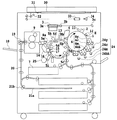
図1は従来用いられている一般的なカラー画像形成装置の概略構成図を示す。
【0003】
本従来例のカラー画像形成装置は、上部にデジタルカラー画像リーダ部、下部にデジタルカラー画像プリンタ部を有する。
【0004】
リーダ部において、原稿30を原稿台ガラス31上に載せ、露光ランプ32により露光走査した原稿30からの反射光像を、レンズ33によりフルカラーセンサ34に集光して光電変換し、カラー色分解画像信号を得る。カラー色分解画像信号に、増幅回路(図示せず)を経て、ビデオ処理ユニット(図示せず)にて処理を施し、プリンタ部に送出する。
【0005】
プリンタ部において、像担持体である感光ドラム1を時計回り方向に回転自在に担持し、感光ドラム1の周りに前露光ランプ11、コロナ帯電器2、レーザビーム露光光学系3、電位センサ12、4個の現像装置4y、4c、4m、4bk、転写装置5、クリーニング器6を配置する。
【0006】
レーザビーム露光光学系3は、リーダ部からの画像信号を入力し、レーザ出力部(図示せず)にて光信号に変換した後、レーザ光をポリゴンミラー3aで反射し、レンズ3bおよびミラー3cを通って、感光ドラム1の面を線状に走査(ラスタスキャン)する光像Eに変換する。
【0007】
プリンタ部にて画像形成時には、まず、感光ドラム1を時計回り方向に回転させ、前露光ランプ11で除電した後、コロナ帯電器2により一様に帯電し、各分解色ごとに光像Eを照射して静電潜像を形成する。
【0008】
次に、各分解色ごとに所定の現像装置を動作させて、感光ドラム1上の静電潜像を現像し、感光ドラム1上に樹脂を基体としたトナーによる画像を形成する。現像装置4y、4c、4m、4bkは、偏心カム24y、24c、24m、24bkの動作により、各分解色に応じて択一的に感光ドラム1に接近する。
【0009】
さらに、感光ドラム1上のトナー画像を、記録材カセット7より搬送系および転写装置5を介して感光ドラム1と対向した位置に供給された記録材に転写する。転写装置5は、本従来例では転写ドラム5f、転写帯電器5b、記録材を静電吸着させるための吸着帯電器5cとこれと対向する吸着ローラ5g、内側帯電器5d、外側帯電器5eとを有し、回転駆動されるように軸支された転写ドラム5fの周面開口域には誘電体からなる記録材担持シート(図示せず)を円筒状に一体的に張設している。記録材担持シートにはポリカーボネートフィルム等の誘電体シートを使用している。
【0010】
転写ドラム5fを回転させるにしたがって感光ドラム1上のトナー像は転写帯電器5bにより記録材担持シートに担持された記録材上に転写する。
【0011】
このように記録材担持シートに吸着搬送される記録材には所望数の色画像が転写され、フルカラー画像を形成する。
【0012】
4色モードの場合、このようにして4色のトナー像の転写を終了すると記録材を転写ドラム5fから分離爪8a、分離押し上げコロ8bおよび分離帯電器5hの作用によって分離し、熱ローラ定着器9を介してトレイ10に排紙する。
【0013】
他方、転写後感光ドラム1は、表面の残留トナーをクリーニング器6で清掃した後、再度画像形成工程に供する。
【0014】
記録材の両面に画像を形成する場合には、熱ローラ定着器9を排出後、すぐに搬送パス切替ガイド19を駆動し、排紙縦パス20を経て、反転パス21aに導いた後、記録材を一旦停止させ、反転ローラ21bの逆転により、送り込まれた際の後端を先頭にして送り込まれた方向と反対向きに退出させ、記録材を裏返して中間トレイ22にストックする。その後、再び上述した電子写真方式による画像形成工程によってもう一方の面に画像を形成する。
【0015】
また、転写ドラム5f上の記録材担持シート上には、感光ドラム1、現像装置4、クリーニング器6等からの粉体の飛散付着、また記録材のジャム(紙づまり)時にトナーが付着すること、両面画像形成時に記録材上のオイルが付着する場合があること、等により汚染されるが、ファーブラシ14と記録材担持シートを介してファーブラシ14に対向するバックアップブラシ15や、オイル除去ローラ16と記録材担持シートを介してオイル除去ローラ16に対向するバックアップブラシ17の作用により清掃された後、再度画像形成プロセスに供せられる。このような清掃は前回転時、後回転時に行い、また、ジャム発生時に随時行う。
【0016】
また、本従来例においては、転写ドラム偏心カム25を動作させ、転写ドラム5fと一体化しているカムフォロワ5iを作動させることにより、記録材担持シートと感光ドラム1とのギャップを所定タイミングで所定間隔に設定可能な構成としている。例えば、スタンバイ中または電源オフ時には、転写ドラム5fと感光ドラム1の間隔を離し、感光ドラム1の回転駆動から転写ドラム5fの回転を独立させることが可能な構成である。
【0017】
また、各現像装置4y,4c,4m,4bkは第1および第2の攪拌/搬送手段(夫々図示せず)を備えており、両者は現像剤を互いに反対方向に搬送するように構成されている。また、第1攪拌/搬送手段の上方には現像スリーブ(図示せず)が配置されている。
【0018】
上記の一連の画像形成動作において現像装置4は、以下のように動作している。静電潜像が現像位置に達するときに、現像バイアス電源(図示せず)からAC電圧とDC電圧が重畳された現像バイアスが現像スリーブに印加され、現像スリーブ駆動装置(図示せず)により現像スリーブが所定方向に回転し、現像装置4は現像加圧カム24により感光ドラム1の方へと加圧され、静電潜像を可視像化する。
【0019】
また、図2に概略構成図を示す濃度検知センサ13は、発光素子として近赤外光のLED、受光素子としてフォトダイオード(PD)を用いて、顕像化されたトナー像の載った転写ドラム5fからの正反射光と乱反射光に基づき濃度を検出するものである。その方法について以下に述べる。
【0020】
13e、13f、13gはフォトダイオード、13h、13iはプリズムである。LED13cによる照射光は、プリズム13hにより、入射面に対して垂直方向に振動する成分(s波光)、入射面に対して平行方向に振動する成分(p波光)とに分離される。s波光はフォトダイオード13eに、p波光はトナー面に照射される。
【0021】
感光体や中間転写体など濃度検知する際の下地となる面に入射したp波光は、ほぼ正反射してp波としてプリズム13iを通過してフォトダイオード13fに入射する。トナー面に照射されたp波光は乱反射して、s波とp波になり、プリズム13iを通過してp波はフォトダイオード13fに入射し正反射光を、s波はフォトダイオード13gに入射し、乱反射光をそれぞれ検出する。
【0022】
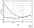
ここで、図3にトナー濃度に対するフォトダイオード13f、13gそれぞれの出力を示す。これによると、実際にはフォトダイオード13fにも乱反射成分が入射しているものと考えられる。そのため、フォトダイオード13fの出力からフォトダイオード13gの出力にある補正係数kを乗じたものを引くこと、即ち、
補正出力=(p波出力)−k×(s波出力)
で図4に示すような真の正反射出力が得られる。
【0023】
こうして検出したトナー像濃度から、階調性を維持するために以下のような制御を行っている。
【0024】
8bit即ち、量子化値でレベル0〜255の入力信号のうち、0、32、64、96、128、160、192、224、255レベルのトナーパッチを形成し、濃度検知センサ13にて読み取り、補間、逆変換等を行い、γLUT(γルックアップテーブル)を作成するものである。
【0025】
【発明が解決しようとする課題】
上記従来のγLUT作成方法では、入力信号のレベル数が多すぎると制御精度は向上するが、制御時間がかかったり、制御により消費するトナー量が増大する。一方、入力信号のレベル数が少なすぎると制御精度が低下するといった問題がある。
【0026】
本発明の目的は、上記の課題を解決することのできる画像形成装置およびその階調制御方法を提供することである。
【0027】
【課題を解決するための手段】
請求項1の発明は、画像信号に応じた潜像が形成される像担持体と、前記潜像に基づいた可視像が転写される像転写体と、前記像転写体に形成された可視像の濃度を検出する検出手段と、異なる濃度レベルの信号で形成された複数のパッチパターンを前記検出手段により読み取ってγ変換テーブルを作成する変換手段と、前記変換手段により作成されたγ変換テーブルを用いて出力画像の階調を制御する制御手段とを備えた画像形成装置において、前記複数のパッチパターンの形成に先立って、基準となる所定濃度レベルの基準パッチパターンを前記像転写体上に形成する基準濃度作成手段と、前記検出手段により読み取った前記基準パッチパターンの濃度を基準濃度と比較する比較手段と、前記基準パッチパターンを読み取った濃度が前記基準濃度よりも高い場合には、前記複数のパッチパターンのうち前記所定濃度レベルよりも低濃度のパッチパターンの数が前記所定濃度レベルよりも高濃度のパッチパターンの数よりも多くなるよう形成すべき前記複数のパッチパターンの濃度レベルを決定し、前記基準パッチパターンを読み取った濃度が前記基準濃度よりも低い場合には、前記複数のパッチパターンのうち前記所定濃度レベルよりも低濃度のパッチパターンの数が前記所定濃度レベルよりも高濃度のパッチパターンの数より少なくなるよう形成すべき前記複数のパッチパターンの濃度レベルを決定するレベル決定手段と、を有する。
【0028】
請求項2の発明は、請求項1に記載の画像形成装置において、請求項1に記載の画像形成装置において、前記基準濃度は一つであり、全濃度領域のほぼ中間濃度である。
【0030】
請求項3の発明は、画像信号に応じた潜像が形成される像担持体と、前記潜像に基づいた可視像が転写される像転写体と、前記像転写体に形成された可視像の濃度を検出する検出手段と、異なる濃度レベルの信号で形成された複数のパッチパターンを前記検出手段により読み取ってγ変換テーブルを作成する変換手段と、前記変換手段により作成されたγ変換テーブルを用いて出力画像の階調を制御する制御手段とを備えた画像形成装置の階調制御方法において、前記複数のパッチパターンの作成に先立って、基準となる所定濃度レベルの基準パッチパターンを前記像転写体上に形成する基準濃度作成ステップと、前記検出手段を用いて読み取った基準パッチパターンの濃度を基準濃度と比較する比較ステップと、前記基準パッチパターンを読み取った濃度が前記基準濃度よりも高い場合には、前記複数のパッチパターンのうち前記所定濃度レベルよりも低濃度のパッチパターンの数が前記所定濃度レベルよりも高濃度のパッチパターンの数よりも多くなるよう形成すべき前記複数のパッチパターンの濃度レベルを決定し、前記基準パッチパターンを読み取った濃度が前記基準濃度よりも低い場合には、前記複数のパッチパターンのうち前記所定濃度レベルよりも低濃度のパッチパターンの数が前記所定濃度レベルよりも高濃度のパッチパターンの数より少なくなるよう形成すべき前記複数のパッチパターンの濃度レベルを決定するレベル決定ステップと、有する。
【0031】
請求項4の発明は、請求項3に記載の階調制御方法において、前記比較ステップにおいて、全濃度領域のほぼ中間濃度を基準濃度として用いる。
【0036】
【発明の実施の形態】
以下、本発明に係る画像形成装置およびその階調制御方法を図面を参照して更に詳しく説明する。なお、下記の実施形態の説明においては、本発明は前出の画像形成装置およびその階調制御方法に具現化するものとし、したがって、画像形成装置の全体的構成、機能についての詳しい説明は省略し、本発明の特徴部分について説明する。
【0037】
(第1実施形態)
本発明の第1実施形態について説明する。
【0038】
本実施形態における階調制御工程においては、まず基準となる濃度レベルのトナーパッチとしてレベル0〜255のうちレベル128のトナーパッチを形成する。そのパッチを濃度検知センサ13にて読み取る。読み取った濃度が予め定めている所定濃度より高い場合には、複数レベルの濃度信号のトナーパッチパターン群の信号を0、16、32、48、64、128、192、255としてトナーパッチを形成し、補間、逆変換等によりγLUTを作成する。逆にレベル128の基準濃度レベルのトナーパッチが所定濃度より低い場合には、複数レベルの濃度信号のトナーパッチパターン群の信号を0、64、128、192、208、224、240、255としてトナーパッチを形成し、補間、逆変換等によりγLUTを作成する。
【0039】
これは以下の考え方に基づいている。
【0040】
ある基準状態で図5のようなγ特性を示す系において、基準状態より高濃度側に階調特性が変化した場合には例えば図6のようになる。このとき従来例のように階調制御に用いるトナーパッチ群の信号レベルが固定値であると、高濃度部分において、階調変化が少ない部分の情報も検知することとなり、あまり有効でない。その分を階調の変化の仕方の大きい低濃度部分の検知に用いるほうが有効である。また、基準状態より低濃度側に階調特性が変化した場合には例えば図7のようになる。このとき従来例のように階調制御に用いるトナーパッチ群の信号レベルが固定値であると、低濃度部分において、階調変化が少ない部分の情報も検知することとなり、あまり有効でない。その分を階調の変化の仕方の大きい高濃度部分の検知に用いるほうが有効である。
【0041】
上記のような考え方に基づき本実施形態では、基準となる濃度レベルが所定濃度より高い場合には、複数レベルの濃度信号のトナーパッチパターン群の信号を0、16、32、48、64、128、192、255と低濃度重視にしてトナーパッチを形成し、逆に基準濃度レベルのトナーパッチが所定濃度より低い場合には、複数レベルの濃度信号のトナーパッチパターン群の信号を0、64、128、192、208、224、240、255と高濃度重視としてトナーパッチを形成し、補間、逆変換等によりγLUTを作成する。
【0042】
以上説明した通り本実施形態の画像形成装置は、画像信号に応じた潜像が形成される像担持体と、露光、現像を経て該潜像に基づいた可視像が転写される像転写体と、可視像化されたトナー像濃度を検出する光センサとを備え、複数レベルの濃度信号のトナーパッチパターン群を形成、該光センサにて読み取り、γテーブルを作成するカラー画像形成装置であって、基準レベルのトナーパッチの読み取り信号と一つの基準濃度(所定濃度)との比較結果に応じて、該複数レベルの濃度信号のトナーパッチパターン群の信号レベルを2通りに異ならせるように構成したことにより、制御時間を長くすることなく、高精度な階調制御を行うことができた。
【0043】
(第2実施形態)
本実施形態は第1実施形態をより細かく制御した例である。第1実施形態と同様の部分は省略し、説明する。
【0044】
本実施形態における階調制御工程においては、まず基準となる濃度レベルのトナーパッチとしてレベル0〜255のうちレベル128のトナーパッチを形成する。そのパッチを濃度検知センサ13にて読み取る。読み取った濃度が予め定めている所定濃度1より高い場合には、複数レベルの濃度信号のトナーパッチパターン群の信号を0、8、16、24、82、140、198、255としてトナーパッチを形成し、予め定めている所定濃度1より低く、所定濃度2(<所定濃度1)より高い場合には、複数レベルの濃度信号のトナーパッチパターン群の信号を0、16、32、48、64、128、192、255としてトナーパッチを形成し、予め定めている所定濃度2より低く、所定濃度3(<所定濃度2)より高い場合には、複数レベルの濃度信号のトナーパッチパターン群の信号を0、58、116、174、232、240、248、255としてトナーパッチを形成し、予め定めている所定濃度3より低い場合には、複数レベルの濃度信号のトナーパッチパターン群の信号を0、64、128、192、208、224、240、255としてトナーパッチを形成し、補間、逆変換等によりγLUTを作成する。
【0045】
以上説明した通り本実施形態の画像形成装置は、画像信号に応じた潜像が形成される像担持体と、露光、現像を経て該潜像に基づいた可視像が転写される像転写体と、可視像化されたトナー像濃度を検出する光センサとを備え、複数レベルの濃度信号のトナーパッチパターン群を形成、該光センサにて読み取り、γテーブルを作成するカラー画像形成装置であって、基準レベルのトナーパッチの読み取り信号と互いに濃度が異なる複数の基準濃度(所定濃度1,2,3)との比較結果に応じて、該複数レベルの濃度信号のトナーパッチパターン群の信号レベルを4通りに異ならせるように構成したことにより、制御時間を長くすることなく、第1実施形態と比べてより高精度な階調制御を行うことができた。
【0046】
(第3実施形態)
本実施形態は複数のプリンタを一元管理し、出力の制御を行う、クラスタプリンティングに本発明を適用した例である。プリンタの構成および機能は第1および第2実施形態と同様であり、これら同様の部分についての説明は省略して本実施形態につき説明する。
【0047】
本実施形態は図8に概略構成図を示したような1サーバ、2RIP、2プリンタからなるクラスタプリンティングシステムである。
【0048】
クラスタプリンティングシステムでは、トータルでの生産性向上を得るために例えば100ページからなる出力ファイルをプリンタ1で50ページ、プリンタ2で50ページ出力するような使用例がある。その際に2台のプリンタ間の色味が異なっていては品質の高いシステムとは言えない。
【0049】
そこで本実施形態では本発明を適用し、各々の装置に濃度検知センサを搭載し、第1実施形態で記した高精度な階調制御工程を設けることで、異なる2台間の濃度を精度良く合わせることができ、高品質なクラスタプリンティングシステムを提供することができた。
【0050】
【発明の効果】
以上説明したように本発明に係る画像形成装置およびその階調制御方法によれば、画像信号に応じた潜像が形成される像担持体と、露光、現像を経て潜像に基づいた可視像が転写される像転写体と、可視像化されたトナー像濃度を検出する光センサとを備えるカラー画像形成装置において、複数レベルの濃度信号のトナーパッチパターン群を形成して光センサにて読み取り、γテーブルを作成する画像形成装置で、基準レベルのトナーパッチの読み取り信号に応じて、複数レベルの濃度信号のトナーパッチパターン群の信号レベルを異ならせることにより、制御時間を長くすることなく、高精度な階調制御を行える効果がある。
【0051】
また、基準レベルのトナーパッチの読み取り濃度が高い場合には、複数のパッチパターンの低濃度信号部分を高濃度信号部分よりも多くして、読み取った濃度が基準濃度よりも低い場合には、複数のパッチパターンの低濃度信号部分を高濃度信号部分より少なくするようにγ変換テーブルを作成することにより、制御時間を長くすることなく、高精度な階調制御を行える効果がある。
【図面の簡単な説明】
【図1】本発明に係る各実施形態および従来例に示した画像形成装置の全体構成図である。
【図2】図1中の濃度検知センサの構成図である
【図3】従来例で示した濃度検知センサでの濃度に対するセンサ出力を示す特性図である。
【図4】従来例で示した濃度検知センサでの濃度に対する補正センサ出力を示す特性図である。
【図5】本発明に係る第1実施形態の基準状態でのγ特性を示す特性図である。
【図6】本発明に係る第1実施形態の高濃度状態でのγ特性を示す特性図である。
【図7】本発明に係る第1実施形態の低濃度状態でのγ特性を示す特性図である。
【図8】本発明に係る第3実施形態のクラスタプリンティングシステムを示す模式図である。
【符号の説明】
1 感光ドラム(感光体)
2 コロナ帯電器
3 レーザビーム露光光学系
3a ポリゴンミラー
3b レンズ
3c ミラー
4,4y,4c,4m,4bk 現像装置
5 転写装置
5b 転写帯電器
5c 吸着帯電器
5d 内側帯電器
5e 外側帯電器
5f 転写ドラム
5g 吸着ローラ
5h 分離帯電器
5i カムフォロワ
6 クリーニング器
7 記録材カセット
8a 分離爪
8b コロ
9 熱ローラ定着器
10 トレイ
11 前露光ランプ
12 電位センサ
13 濃度検知センサ
13c LED
13e,13f,13g フォトダイオード
13h,13i プリズム
14 ファーブラシ
15,17 バックアップブラシ
16 オイル除去ローラ
19 搬送パス切替ガイド
20 排紙縦パス
21a 反転パス
21b 反転ローラ
22 中間トレイ
24 現像加圧カム
24y,24c,24m,24bk 偏心カム
25 転写ドラム偏心カム
30 原稿
31 原稿台ガラス
32 露光ランプ
33 レンズ
34 フルカラーセンサ[0001]
BACKGROUND OF THE INVENTION
The present invention relates to an image forming apparatus and a gradation control method thereof, and more particularly to an image forming apparatus such as a laser beam printer and an electrostatic recording apparatus and a gradation control method thereof.
[0002]
[Prior art]
FIG. 1 is a schematic configuration diagram of a general color image forming apparatus conventionally used.
[0003]
The conventional color image forming apparatus has a digital color image reader unit in the upper part and a digital color image printer unit in the lower part.
[0004]
In the reader section, the original 30 is placed on the
[0005]
In the printer unit, a
[0006]
The laser beam exposure
[0007]
At the time of image formation by the printer unit, first, the
[0008]
Next, a predetermined developing device is operated for each separation color to develop the electrostatic latent image on the
[0009]
Further, the toner image on the
[0010]
As the transfer drum 5f is rotated, the toner image on the
[0011]
In this way, a desired number of color images are transferred to the recording material sucked and conveyed by the recording material carrying sheet, thereby forming a full-color image.
[0012]
In the four-color mode, when the transfer of the four-color toner images is completed in this manner, the recording material is separated from the transfer drum 5f by the action of the
[0013]
On the other hand, after the transfer, the
[0014]
When images are to be formed on both sides of the recording material, after the heat roller fixing device 9 is discharged, the conveyance
[0015]
Further, the toner adheres to the recording material carrying sheet on the transfer drum 5f when the
[0016]
In this conventional example, the transfer drum
[0017]
Each of the developing
[0018]
In the series of image forming operations described above, the developing
[0019]
2 is a transfer drum on which a visualized toner image is placed using a near-infrared light LED as a light emitting element and a photodiode (PD) as a light receiving element. The density is detected based on regular reflection light and irregular reflection light from 5f. The method will be described below.
[0020]
[0021]
The p-wave light incident on the surface serving as a base for density detection, such as a photoconductor or an intermediate transfer member, is substantially specularly reflected and passes through the prism 13i as a p-wave and enters the photodiode 13f. The p-wave light applied to the toner surface is irregularly reflected to become s-wave and p-wave, passes through the prism 13i, the p-wave is incident on the photodiode 13f and is specularly reflected, and the s-wave is incident on the
[0022]
FIG. 3 shows the outputs of the
Correction output = (p wave output) −k × (s wave output)
Thus, a true regular reflection output as shown in FIG. 4 is obtained.
[0023]
The following control is performed in order to maintain the gradation from the toner image density thus detected.
[0024]
8 bits, that is, 0, 32, 64, 96, 128, 160, 192, 224, 255 level toner patches are formed among the input signals of quantized values of
[0025]
[Problems to be solved by the invention]
In the above conventional γLUT creation method, if the number of levels of the input signal is too large, the control accuracy is improved, but the control time is increased and the amount of toner consumed by the control is increased. On the other hand, if the number of levels of the input signal is too small, there is a problem that the control accuracy is lowered.
[0026]
An object of the present invention is to provide an image forming apparatus and a gradation control method thereof that can solve the above-described problems.
[0027]
[Means for Solving the Problems]
According to the first aspect of the present invention, there is provided an image carrier on which a latent image corresponding to an image signal is formed, an image transfer body to which a visible image based on the latent image is transferred, and an image formed on the image transfer body. Detection means for detecting the density of a visual image, conversion means for reading a plurality of patch patterns formed by signals of different density levels by the detection means to create a γ conversion table, and γ conversion created by the conversion means An image forming apparatus comprising a control means for controlling the gradation of an output image using a table, prior to the formation of the plurality of patch patterns, a reference patch pattern having a predetermined density level as a reference is formed on the image transfer body. A reference density creating means formed on the image forming apparatus, a comparing means for comparing a density of the reference patch pattern read by the detecting means with a reference density, and a density read from the reference patch pattern When the density is higher than the quasi-density, the number of patch patterns having a density lower than the predetermined density level among the plurality of patch patterns is larger than the number of patch patterns having a higher density than the predetermined density level. And determining a density level of the plurality of patch patterns, and when the density read from the reference patch pattern is lower than the reference density, a patch pattern having a density lower than the predetermined density level among the plurality of patch patterns Level determination means for determining density levels of the plurality of patch patterns to be formed so that the number of patch patterns is less than the number of patch patterns having a higher density than the predetermined density level.
[0028]
According to a second aspect of the present invention, in the image forming apparatus according to the first aspect, in the image forming apparatus according to the first aspect, the reference density is one, which is substantially an intermediate density in the entire density region.
[0030]
According to a third aspect of the present invention, there is provided an image carrier on which a latent image corresponding to an image signal is formed, an image transfer body to which a visible image based on the latent image is transferred, and an image formed on the image transfer body. Detection means for detecting the density of a visual image, conversion means for reading a plurality of patch patterns formed by signals of different density levels by the detection means to create a γ conversion table, and γ conversion created by the conversion means In a gradation control method for an image forming apparatus comprising a control means for controlling the gradation of an output image using a table, a reference patch pattern having a predetermined density level as a reference is created prior to the creation of the plurality of patch patterns. A reference density creation step formed on the image transfer member, a comparison step of comparing the density of the reference patch pattern read using the detection means with a reference density, and the reference patch pattern read When the captured density is higher than the reference density, the number of patch patterns having a lower density than the predetermined density level among the plurality of patch patterns is greater than the number of patch patterns having a higher density than the predetermined density level. When the density of the plurality of patch patterns to be formed is determined and the density read from the reference patch pattern is lower than the reference density, the density level of the plurality of patch patterns is lower than the predetermined density level. And a level determining step for determining density levels of the plurality of patch patterns to be formed so that the number of low density patch patterns is smaller than the number of patch patterns having a higher density than the predetermined density level.
[0031]
According to a fourth aspect of the present invention, in the gradation control method according to the third aspect, in the comparison step, a substantially intermediate density of all density areas is used as a reference density.
[0036]
DETAILED DESCRIPTION OF THE INVENTION
Hereinafter, an image forming apparatus and a gradation control method thereof according to the present invention will be described in more detail with reference to the drawings. In the following description of the embodiments, the present invention is embodied in the above-described image forming apparatus and its gradation control method, and therefore detailed description of the overall configuration and functions of the image forming apparatus is omitted. The features of the present invention will be described.
[0037]
(First embodiment)
A first embodiment of the present invention will be described.
[0038]
In the gradation control process in the present embodiment, first, a toner patch of level 128 out of
[0039]
This is based on the following concept.
[0040]
In a system that exhibits the γ characteristic as shown in FIG. 5 in a certain reference state, when the gradation characteristic changes to a higher density side than the reference state, for example, FIG. At this time, if the signal level of the toner patch group used for gradation control is a fixed value as in the conventional example, information on a portion with little gradation change is detected in the high density portion, which is not very effective. It is more effective to use that amount for detecting a low density portion where the gradation changes greatly. Further, when the gradation characteristic is changed to a lower density side than the reference state, for example, as shown in FIG. At this time, if the signal level of the toner patch group used for gradation control is a fixed value as in the conventional example, information on a portion with little gradation change is detected in the low density portion, which is not very effective. It is more effective to use that amount for detecting a high density portion where the gradation changes greatly.
[0041]
Based on the above concept, in the present embodiment, when the reference density level is higher than a predetermined density, the toner patch pattern group signals of a plurality of density signals are set to 0, 16, 32, 48, 64, 128. , 192, 255 and emphasizing the low density, the toner patch is formed. Conversely, when the toner patch of the reference density level is lower than the predetermined density, the signal of the toner patch pattern group of the density signal of the plurality of levels is set to 0, 64, 128, 192, 208, 224, 240, and 255, toner patches are formed with an emphasis on high density, and a γLUT is created by interpolation, inverse transformation, or the like.
[0042]
As described above, the image forming apparatus according to this embodiment includes an image carrier on which a latent image corresponding to an image signal is formed, and an image transfer body on which a visible image based on the latent image is transferred through exposure and development. And a color image forming apparatus for forming a γ table by forming a toner patch pattern group of density signals of a plurality of levels, reading with the optical sensor, and a photosensor for detecting a visualized toner image density Thus, the signal level of the toner patch pattern group of the plurality of density signals is made to differ in two ways according to the comparison result between the read signal of the reference level toner patch and one reference density (predetermined density). As a result, it was possible to perform highly accurate gradation control without increasing the control time.
[0043]
(Second Embodiment)
This embodiment is an example in which the first embodiment is more finely controlled. The same parts as in the first embodiment will be omitted and described.
[0044]
In the gradation control process in the present embodiment, first, a toner patch of level 128 out of
[0045]
As described above, the image forming apparatus according to this embodiment includes an image carrier on which a latent image corresponding to an image signal is formed, and an image transfer body on which a visible image based on the latent image is transferred through exposure and development. And a color image forming apparatus for forming a γ table by forming a toner patch pattern group of density signals of a plurality of levels, reading with the optical sensor, and a photosensor for detecting a visualized toner image density According to the comparison result between the read signal of the reference level toner patch and a plurality of reference densities having different densities (predetermined
[0046]
(Third embodiment)
This embodiment is an example in which the present invention is applied to cluster printing in which a plurality of printers are centrally managed and output is controlled. The configuration and functions of the printer are the same as those in the first and second embodiments, and description of these similar parts will be omitted and only this embodiment will be described.
[0047]
This embodiment is a cluster printing system including one server, two RIPs, and two printers as shown in the schematic configuration diagram of FIG.
[0048]
In the cluster printing system, there is a usage example in which an output file consisting of 100 pages, for example, is output 50 pages by the
[0049]
Therefore, in this embodiment, the present invention is applied, each device is equipped with a density detection sensor, and the high-accuracy gradation control process described in the first embodiment is provided, so that the density between two different units can be accurately adjusted. We were able to provide a high-quality cluster printing system.
[0050]
【The invention's effect】
As described above, according to the image forming apparatus and the gradation control method thereof according to the present invention, an image carrier on which a latent image corresponding to an image signal is formed, and a visible image based on the latent image through exposure and development. In a color image forming apparatus including an image transfer body to which an image is transferred and a photosensor for detecting the density of a visualized toner image, a toner patch pattern group of a plurality of levels of density signals is formed to form an optical sensor. In the image forming apparatus that creates a γ table, the control time is lengthened by changing the signal level of the toner patch pattern group of the multi-level density signal according to the read signal of the reference level toner patch. In addition, there is an effect that gradation control with high accuracy can be performed.
[0051]
In addition, when the reading density of the reference level toner patch is high, the number of low density signal portions of the plurality of patch patterns is made larger than that of the high density signal portion, and when the read density is lower than the reference density, By creating the γ conversion table so that the low density signal portion of the patch pattern is less than the high density signal portion, there is an effect that high-precision gradation control can be performed without lengthening the control time.
[Brief description of the drawings]
FIG. 1 is an overall configuration diagram of an image forming apparatus shown in each embodiment and a conventional example according to the present invention.
2 is a configuration diagram of the density detection sensor in FIG. 1. FIG. 3 is a characteristic diagram showing sensor output with respect to density in the density detection sensor shown in the conventional example.
FIG. 4 is a characteristic diagram showing a correction sensor output with respect to density in the density detection sensor shown in the conventional example.
FIG. 5 is a characteristic diagram showing a γ characteristic in a reference state according to the first embodiment of the present invention.
FIG. 6 is a characteristic diagram showing a γ characteristic in a high concentration state of the first embodiment according to the present invention.
FIG. 7 is a characteristic diagram showing a γ characteristic in a low concentration state of the first embodiment according to the present invention.
FIG. 8 is a schematic diagram showing a cluster printing system according to a third embodiment of the present invention.
[Explanation of symbols]
1 Photosensitive drum (photoconductor)
2
13e, 13f,
Claims (4)
前記複数のパッチパターンの形成に先立って、基準となる所定濃度レベルの基準パッチパターンを前記像転写体上に形成する基準濃度作成手段と、
前記検出手段により読み取った前記基準パッチパターンの濃度を基準濃度と比較する比較手段と、
前記基準パッチパターンを読み取った濃度が前記基準濃度よりも高い場合には、前記複数のパッチパターンのうち前記所定濃度レベルよりも低濃度のパッチパターンの数が前記所定濃度レベルよりも高濃度のパッチパターンの数よりも多くなるよう形成すべき前記複数のパッチパターンの濃度レベルを決定し、前記基準パッチパターンを読み取った濃度が前記基準濃度よりも低い場合には、前記複数のパッチパターンのうち前記所定濃度レベルよりも低濃度のパッチパターンの数が前記所定濃度レベルよりも高濃度のパッチパターンの数より少なくなるよう形成すべき前記複数のパッチパターンの濃度レベルを決定するレベル決定手段と、
を有することを特徴とする画像形成装置。An image carrier on which a latent image corresponding to an image signal is formed, an image transfer body to which a visible image based on the latent image is transferred, and a density of the visible image formed on the image transfer body are detected. A detection unit; a conversion unit that reads a plurality of patch patterns formed by signals of different density levels by the detection unit to create a γ conversion table; and a γ conversion table created by the conversion unit, In an image forming apparatus comprising a control means for controlling gradation,
Prior to the formation of the plurality of patch patterns, a reference density creating means for forming a reference patch pattern of a predetermined density level serving as a reference on the image transfer member;
Comparison means for comparing the density of the reference patch pattern read by the detection means with a reference density;
If the density read from the reference patch pattern is higher than the reference density, the number of patch patterns whose density is lower than the predetermined density level among the plurality of patch patterns is higher than the predetermined density level. The density levels of the plurality of patch patterns to be formed are determined so as to be larger than the number of patterns, and when the density read from the reference patch pattern is lower than the reference density, the patch pattern among the plurality of patch patterns Level determining means for determining the density levels of the plurality of patch patterns to be formed so that the number of patch patterns having a lower density than the predetermined density level is less than the number of patch patterns having a higher density than the predetermined density level;
An image forming apparatus comprising:
前記複数のパッチパターンの作成に先立って、基準となる所定濃度レベルの基準パッチパターンを前記像転写体上に形成する基準濃度作成ステップと、
前記検出手段を用いて読み取った基準パッチパターンの濃度を基準濃度と比較する比較ステップと、
前記基準パッチパターンを読み取った濃度が前記基準濃度よりも高い場合には、前記複数のパッチパターンのうち前記所定濃度レベルよりも低濃度のパッチパターンの数が前記所定濃度レベルよりも高濃度のパッチパターンの数よりも多くなるよう形成すべき前記複数のパッチパターンの濃度レベルを決定し、前記基準パッチパターンを読み取った濃度が前記基準濃度よりも低い場合には、前記複数のパッチパターンのうち前記所定濃度レベルよりも低濃度のパッチパターンの数が前記所定濃度レベルよりも高濃度のパッチパターンの数より少なくなるよう形成すべき前記複数のパッチパターンの濃度レベルを決定するレベル決定ステップと、
有することを特徴とする階調制御方法。An image carrier on which a latent image corresponding to an image signal is formed, an image transfer body to which a visible image based on the latent image is transferred, and a density of the visible image formed on the image transfer body are detected. A detection unit; a conversion unit that reads a plurality of patch patterns formed by signals of different density levels by the detection unit to create a γ conversion table; and a γ conversion table created by the conversion unit, In a gradation control method for an image forming apparatus comprising a control means for controlling gradation,
Prior to the creation of the plurality of patch patterns, a reference density creation step of forming a reference patch pattern of a predetermined density level as a reference on the image transfer body;
A comparison step of comparing the density of the reference patch pattern read using the detection means with a reference density;
If the density read from the reference patch pattern is higher than the reference density, the number of patch patterns whose density is lower than the predetermined density level among the plurality of patch patterns is higher than the predetermined density level. The density levels of the plurality of patch patterns to be formed are determined so as to be larger than the number of patterns, and when the density read from the reference patch pattern is lower than the reference density, the patch pattern among the plurality of patch patterns A level determining step for determining density levels of the plurality of patch patterns to be formed so that the number of patch patterns having a lower density than a predetermined density level is less than the number of patch patterns having a higher density than the predetermined density level;
A gradation control method comprising:
前記比較ステップにおいて、全濃度領域のほぼ中間濃度を基準濃度として用いることを特徴とする階調制御方法。The gradation control method according to claim 3,
A gradation control method characterized in that, in the comparison step, a substantially intermediate density of all density areas is used as a reference density.
Priority Applications (1)
| Application Number | Priority Date | Filing Date | Title |
|---|---|---|---|
| JP2002030057A JP4006236B2 (en) | 2002-02-06 | 2002-02-06 | Image forming apparatus and gradation control method thereof |
Applications Claiming Priority (1)
| Application Number | Priority Date | Filing Date | Title |
|---|---|---|---|
| JP2002030057A JP4006236B2 (en) | 2002-02-06 | 2002-02-06 | Image forming apparatus and gradation control method thereof |
Publications (3)
| Publication Number | Publication Date |
|---|---|
| JP2003228203A JP2003228203A (en) | 2003-08-15 |
| JP2003228203A5 JP2003228203A5 (en) | 2007-06-07 |
| JP4006236B2 true JP4006236B2 (en) | 2007-11-14 |
Family
ID=27750300
Family Applications (1)
| Application Number | Title | Priority Date | Filing Date |
|---|---|---|---|
| JP2002030057A Expired - Fee Related JP4006236B2 (en) | 2002-02-06 | 2002-02-06 | Image forming apparatus and gradation control method thereof |
Country Status (1)
| Country | Link |
|---|---|
| JP (1) | JP4006236B2 (en) |
Families Citing this family (2)
| Publication number | Priority date | Publication date | Assignee | Title |
|---|---|---|---|---|
| JP4165706B2 (en) | 2004-01-26 | 2008-10-15 | 株式会社リコー | Document reading apparatus and image forming apparatus |
| JP5171165B2 (en) * | 2007-08-29 | 2013-03-27 | キヤノン株式会社 | Image forming apparatus |
-
2002
- 2002-02-06 JP JP2002030057A patent/JP4006236B2/en not_active Expired - Fee Related
Also Published As
| Publication number | Publication date |
|---|---|
| JP2003228203A (en) | 2003-08-15 |
Similar Documents
| Publication | Publication Date | Title |
|---|---|---|
| JPH1165315A (en) | Image forming device | |
| US20030049039A1 (en) | Control method and image forming apparatus | |
| JP2006287708A (en) | Image processing system | |
| JP2957859B2 (en) | Image forming device | |
| US6456803B2 (en) | Image forming apparatus capable of detecting both of regularly reflected light and irregularly reflected light | |
| JP2003076129A (en) | Image forming apparatus | |
| JP2001215850A (en) | Image forming apparatus | |
| JP4978078B2 (en) | Image forming apparatus control method and image forming apparatus | |
| JP4006236B2 (en) | Image forming apparatus and gradation control method thereof | |
| JP2004240369A (en) | Image forming apparatus | |
| JP4635716B2 (en) | Image forming apparatus and image forming method | |
| JP2011090580A (en) | Management system for image forming apparatus | |
| JP2002072574A (en) | Image-forming device | |
| JP2004184583A (en) | Image forming method and image forming apparatus | |
| JP2003098798A (en) | Image forming apparatus | |
| JP2003215981A (en) | Image forming method and device thereof | |
| JP2000172147A (en) | Image forming device | |
| JP2003202710A (en) | Image forming device | |
| JP2003241446A (en) | Image forming apparatus, gradation control method therefor, and print system | |
| JP2021015214A (en) | Image forming apparatus and image forming method | |
| JPS6343189A (en) | Image forming device | |
| JP2002072577A (en) | Image-forming device | |
| JP2003029476A (en) | Image forming apparatus | |
| JPH11160927A (en) | Image density controller and image forming device | |
| JP2000199986A (en) | Image forming device and image forming condition deciding method |
Legal Events
| Date | Code | Title | Description |
|---|---|---|---|
| A521 | Written amendment |
Free format text: JAPANESE INTERMEDIATE CODE: A523 Effective date: 20050207 |
|
| A621 | Written request for application examination |
Free format text: JAPANESE INTERMEDIATE CODE: A621 Effective date: 20050207 |
|
| A521 | Written amendment |
Free format text: JAPANESE INTERMEDIATE CODE: A523 Effective date: 20070416 |
|
| TRDD | Decision of grant or rejection written | ||
| A01 | Written decision to grant a patent or to grant a registration (utility model) |
Free format text: JAPANESE INTERMEDIATE CODE: A01 Effective date: 20070807 |
|
| A61 | First payment of annual fees (during grant procedure) |
Free format text: JAPANESE INTERMEDIATE CODE: A61 Effective date: 20070827 |
|
| R150 | Certificate of patent or registration of utility model |
Free format text: JAPANESE INTERMEDIATE CODE: R150 |
|
| FPAY | Renewal fee payment (event date is renewal date of database) |
Free format text: PAYMENT UNTIL: 20100831 Year of fee payment: 3 |
|
| FPAY | Renewal fee payment (event date is renewal date of database) |
Free format text: PAYMENT UNTIL: 20110831 Year of fee payment: 4 |
|
| FPAY | Renewal fee payment (event date is renewal date of database) |
Free format text: PAYMENT UNTIL: 20120831 Year of fee payment: 5 |
|
| FPAY | Renewal fee payment (event date is renewal date of database) |
Free format text: PAYMENT UNTIL: 20120831 Year of fee payment: 5 |
|
| FPAY | Renewal fee payment (event date is renewal date of database) |
Free format text: PAYMENT UNTIL: 20130831 Year of fee payment: 6 |
|
| LAPS | Cancellation because of no payment of annual fees |