JP4005852B2 - Drum brake - Google Patents
Drum brake Download PDFInfo
- Publication number
- JP4005852B2 JP4005852B2 JP2002171775A JP2002171775A JP4005852B2 JP 4005852 B2 JP4005852 B2 JP 4005852B2 JP 2002171775 A JP2002171775 A JP 2002171775A JP 2002171775 A JP2002171775 A JP 2002171775A JP 4005852 B2 JP4005852 B2 JP 4005852B2
- Authority
- JP
- Japan
- Prior art keywords
- brake
- shoe
- drum
- temperature
- amount
- Prior art date
- Legal status (The legal status is an assumption and is not a legal conclusion. Google has not performed a legal analysis and makes no representation as to the accuracy of the status listed.)
- Expired - Fee Related
Links
Images


Landscapes
- Braking Arrangements (AREA)
Description
【0001】
【発明の属する技術分野】
本発明は、シュー間隙自動調整装置を備えるドラムブレーキに関し、より詳細には、ブレーキが所定の高温に達した時に、ブレーキドラムとブレーキシューの間隙(これ以降、シュー間隙と呼ぶ)の自動調整作用を停止させる過調整防止機構に関するものである。
【0002】
【従来の技術】
一般に、ドラムブレーキは、ブレーキシューのライニングの摩耗を補償してシュー間隙を一定に保つシュー間隙自動調整装置を具備している。長い下り坂等においてサービスブレーキを繰り返して使用すると、ブレーキドラムが高温になり径方向に膨張した分だけシュー間隙が一時的に大きくなる。このような状況下において、あたかもライニングが摩耗したとみなしてシュー間隙自動調整作用を続行してしまうドラムブレーキの構成では、ブレーキドラムが常温まで冷却されて元の大きさに戻った時に、シュー間隙が狭くなり過ぎて引き摺りを惹起するという不具合を生じる。この引き摺りを回避するため、通常のブレーキ使用時(所定の高温に達しない時)のシュー間隙を予め大きく設定すると、シュー間隙の過調整に起因する引き摺りを防止できる反面、ブレーキストロークが大きくなることによる操作フィーリングの悪化や効き遅れの問題を生じる。
【0003】
上述した問題を解決するシュー間隙過調整防止機構を具備したドラムブレーキが、特公昭58−49739号公報に開示されている。このドラムブレーキにおける一対のブレーキシューは、シューリターンスプリングのばね力によるアンカーとの当接点を支点としての戻り位置が、サービスブレーキ用のホイールシリンダに隣接して、両ブレーキシュー間に掛け渡された後退規制装置としてのシュー間隙調整ストラットにより規制されている。
【0004】
前記シュー間隙調整ストラットは、回転不能なおねじ部材(ねじロッド)、このおねじ部材にねじ係合するナット部材(ナット)、及び前記おねじ部材に滑嵌合する回転不能なスリーブ部材(筒胴)を構成要素とし、これに前記ナット部材を回転するためのアジャストレバー(アーム)とアジャストスプリング(爪ばね)を付設してインクリメンタル形のシュー間隙自動調整装置が構成されている。また、シュー間隙調整ストラットの軸線方向に離間可能に滑嵌合する二部材間(上記公報中では、ナット部材とボルト部材からなるねじ係合体とスリーブ部材との間)にシュー間隙過調整防止機構の構成要素である温度感応部材(バイメタル帯片)を介挿している。
【0005】
この温度感応部材は、二つ折りした折り返し重合部におねじ部材を貫通させてスリーブ部材とナット部材間に介挿され、ブレーキが所定の温度に達した時、厳密には温度感応部材が所定の温度に達した時に、シューリターンスプリングのばね力に抗してサービスブレーキを作動すると、温度感応部材の折り返し重合部が拡開してスリーブ部材とねじ係合体を離間し、このねじ係合体を一方のブレーキシューの拡開に追従させると共に、スリーブ部材を他方のブレーキシューの拡開に追従させることにより、シュー間隙の自動調整作用を停止させて過調整を防止するよう構成されている。
【0006】
上述したシュー間隙過調整防止機構は、インクリメンタル形以外のシュー間隙自動調整装置(例えば、ワンショット形)に適用できないため、これを解決するために考えられたのが、特開2002−106620号公報に記載の発明である。このドラムブレーキに具備されるシュー間隙過調整防止機構は、シュー間隙調整ストラットとブレーキシュー間、或いはシュー間隙調整ストラットとブレーキレバー間にバイメタル製や形状記憶合金製の温度感応部材を介挿している。この構成によれば、ワンショット形のシュー間隙自動調整装置にも適用できるので汎用性に富む。
【0007】
代表的なワンショット形のシュー間隙自動調整装置は、ストラット本体、ベルクランク状のアジャストレバー、このアジャストレバーをストラット本体に枢着するピン及び第二スプリングから成るシュー間隙調整ストラットと、ストラット本体と一方のブレーキシュー間に張設した第一スプリングから構成され、サービスブレーキ作動時における一対のブレーキシューの拡開量が所定の値を超えると、ストラット本体が第一スプリングのばね力により一方のブレーキシュー及びブレーキレバーに追従すると共に、他方のブレーキシューがアジャストレバーに作用し、アジャストレバーのストラット本体への係合位置が変位してシュー間隙調整ストラットの全長を伸長し、シュー間隙を自動的に調整するよう構成されている。
【0008】
シュー間隙過調整防止機構は、二つ折りした温度感応部材の折り返し重合部をストラット本体とブレーキレバー間に介挿し、ブレーキドラムが高温になって温度感応部材が所定の温度に達している状態でサービスブレーキを作動すると、温度感応部材の折り返し重合部が第一スプリングのばね力に抗しながら拡開することにより、シュー間隙調整ストラットを他方のブレーキシューに追従させ、シュー間隙の自動調整作用を停止させて過調整を防止するよう構成されている。
【0009】
【発明が解決しようとする課題】
前述したシュー間隙の過調整防止機構においては、以下に記載するような課題があった。
【0010】
<イ> 高温時にブレーキドラムが径方向に膨張している間、シュー間隙の自動調整作用は停止しており、又、ブレーキの非作動時に一対のブレーキシューは、シューリターンスプリングのばね力により温度感応部材の折り返し重合部が圧縮された位置まで戻されるので、シュー間隙はブレーキドラムの膨張分だけ大きくなっている。その結果、繰り返し使用するサービスブレーキの作動ストロークが大きくなって操作フィーリングの悪化を招いたり、ブレーキの効き遅れを生じたりする。
【0011】
<ロ> 前述したインクリメンタル形シュー間隙自動調整装置においては、スリーブ部材と温度感応部材がおねじ部材から離脱可能であるため、シュー間隙調整ストラットの取り扱いやブレーキの組立てが面倒であった。又、ブレーキを分解した際に、温度感応部材を組み忘れたり、紛失したりする恐れがあった。
【0012】
本発明は、以上の問題点に鑑みてなされたもので、ブレーキの高温時におけるシュー間隙の過調整を防止すると共に、ブレーキの非作動時におけるシュー間隙を小さく抑えて、サービスブレーキの操作フィーリングの悪化を抑えると共に、迅速なブレーキの効きを確保できる、ドラムブレーキを提供することを目的としている。
【0013】
【課題を解決するための手段】
上述した目的を達成するために、本発明におけるドラムブレーキにおいては、一対のブレーキシューの隣接する一方端部間にサービスブレーキアクチュエータを配設し、両ブレーキシューの戻り位置を規制して両ブレーキシューのブレーキドラムに対するシュー間隙を決める後退規制装置を前記両ブレーキシューの前記アクチュエータに隣接する対向間に掛け渡し、サービスブレーキ作動時における前記両ブレーキシューの拡開量が所定の値を超えると、前記後退規制装置の前記ブレーキシューとの当接位置を自動的に変位させて前記ブレーキシューの戻り位置をブレーキシューの拡開方向に変位させるシュー間隙自動調整装置を具備すると共に、所定の温度になるとシュー間隙自動調整作用を停止させる方向に前記後退規制装置を付勢してシュー間隙の過調整を防止する温度感応部材を付設したドラムブレーキにおいて、この温度感応部材の温度変形に伴う前記両ブレーキシューの拡開方向への作用力を、前記両ブレーキシューを前記戻り位置に戻す作用力より大きくし、サービスブレーキ非作動時において、前記両ブレーキシューを拡開させるようにしたものである。
【0014】
又、ブレーキが高温になるに連れて大きくなる温度感応部材の温度変形に伴って大きくなる両ブレーキシューの外径の変化量が、同条件下におけるブレーキドラムの熱膨張に伴って大きくなるブレーキドラム内径の変化量と略同量になるよう構成するとよい。
【0015】
又、ブレーキが所定の高温時に、温度感応部材の温度変形に伴う両ブレーキシューの外径の変化量と、同条件下におけるブレーキドラムの熱膨張に伴う内径の変化量とが略同量になるよう規制するストッパ手段を付設するとよい。
【0016】
又、後退規制装置と交差する方向にレバー部材を配設して両ブレーキシューのいずれか一方に回転可能に枢支し、温度感応部材に折り返し重合部を形成し、この折り返し重合部をレバー部材と後退規制装置間に介挿し、この折り返し重合部の拡開量を規制するストッパ手段を付設するとよい。
【0017】
又、後退規制装置と交差する方向にレバー部材を配設して両ブレーキシューのいずれか一方に回転可能に枢支し、このレバー部材の枢支部と自由端部の間を後退規制装置の一端部に係合すると共に、レバー部材の自由端部側の回動戻り位置を支持部材で規制し、温度感応部材に折り返し重合部を形成し、この折り返し重合部をレバー部材の自由端部側と支持部材間に介挿し、この折り返し重合部の拡開量を規制するストッパ装置を付設してもよい。
【0018】
又、後退規制装置が、外周歯を一体に形成する回転可能な部材とこれに螺合して自身は回転不能な部材から成るねじ結合機構を有し、両ブレーキシューの拡開量が所定の値を超えると、外周歯を形成する部材が回転して軸線方向に相対変位し、ブレーキシューの戻り位置を拡開方向に自動的に変位させるよう構成するとよく、更には、外周歯を一体に形成する部材と、これに相対回転可能にかつ離間可能に滑嵌合して自身は回転不能な部材間に温度感応部材の折り返し重合部を介挿すると共に、この折り返し重合部の拡開量を規制するストッパ装置を付設してもよい。
【0019】
又、後退規制装置が、アジャストレバーの一方向への回転を許容する小刻みな歯の噛合機構を有し、両ブレーキシューの拡開量が所定のシュー間隙を超えると、アジャストレバーが回転して小刻みな歯の噛合位置が変位し、ブレーキシューの戻り位置を拡開方向に自動的に変位させるよう構成するとよい。
【0020】
上述のように構成したドラムブレーキによれば、ブレーキドラムが高温になった時、シュー間隙の自動調整作用を停止させる温度感応部材の温度変形に伴う作用力により、シューリターンスプリングのばね力に抗して一対のブレーキシューの戻り位置を規制するから、ブレーキの非作動時におけるシュー間隙を小さく抑えることができ、サービスブレーキの作動ストロークが大きくなることによる操作フィーリングの悪化を抑えられ、迅速なブレーキの効きを確保できる。
【0021】
又、ブレーキが高温になるに連れて大きくなる温度感応部材の温度変形に伴う両ブレーキシューの外径の変化量が、同条件下における前記ブレーキドラムの熱膨張に伴う内径の変化量と略同量になるよう構成すれば、ブレーキの高温時におけるブレーキシューの引き摺りを確実に防止できる。
【0022】
又、ブレーキが所定の高温時における前記温度感応部材の温度変形に伴う前記両ブレーキシューの外径の変化量が、同条件下における前記ブレーキドラムの熱膨張に伴う内径の変化量と略同量になるよう規制するストッパ手段を付設すれば、ブレーキが所定の高温時におけるブレーキシューの引き摺りを確実に防止できる。
【0023】
又、後退規制装置の一端部がレバー部材を介して一方のブレーキシューを支持するドラムブレーキにも適用でき、レバー部材はパーキングブレーキ用のブレーキレバーや一対のブレーキシューの外径をブレーキの外部から手動で以って縮小できる縮径レバーでよく、種々の形式のドラムブレーキに採用できる。
【0024】
又、ねじ結合部を自動的に相対変位させるインクリメンタル形のシュー間隙自動調整装置、或いは、小刻みな歯の噛合部を自動的に相対変位させるワンショット形のシュー間隙自動調整装置にも適用できて汎用性に富む。
【0025】
【発明の実施の形態】
以下、本発明に係わるドラムブレーキの一例について説明する。
【0026】
最初に、本発明の実施例1について、図1〜図3を参照しながら説明する。本例は、インクリメンタル形のシュー間隙自動調整装置及びフォワードプル形のパーキングブレーキ装置を具備するドラムブレーキであって、一対の対向するブレーキシュー10,15は、車両等の不動部に固定されるバックプレート2上に摺動可能となるようにシューホールド機構3,4で以って保持されている。両ブレーキシュー10,15の図1における上方隣接端は、バックプレート2に固定されたサービスブレーキ用のホイールシリンダ5に作動的に係合し、下方隣接端はバックプレート2に固定されたアンカーブロック6に支承されている。
【0027】
図1における左方のブレーキシュー10には、そのシューウェブ12に重合してパーキングブレーキ用のブレーキレバー20が配設されている。ブレーキレバー20の基部20aはシューウェブ12の上方端部にピン21で以って回転可能に枢支され、アンカーブロック6側に位置する自由端部20bに遠隔力伝達部材であるブレーキケーブル22が接続される。又、自由端部20bに近い左方側に、シューリム11に当接する突起20cを形成している。
【0028】
ホイールシリンダ5に隣接して、ブレーキシュー15とブレーキレバー20の間にシュー間隙調整ストラット31が掛け渡され、一対のブレーキシュー10,15間に張設されたシューリターンスプリング7,8のばね力で以って両ブレーキシュー10,15が前記ストラット31に当接し、戻り位置が規制されている。
【0029】
両ブレーキシュー10,15の後退規制装置としての前記シュー間隙調整ストラット31は、アジャストボルト32とアジャストナット33及びソケット部材34から成り、これにアジャストレバー37とアジャストスプリング38及びピン39を付加してシュー間隙自動調整装置30を構成している。又、シュー間隙調整ストラット31に温度感応部材35とストッパピン36からなるシュー間隙の過調整防止機構を付設している。
【0030】
シュー間隙自動調整機構を構成するアジャストレバー37等は、図1に示すようにブレーキシュー15上に備えられている。アジャストレバー37は、シューウェブ17に植設したピン39に回転可能に枢支され、この枢支部から二股に伸長する一方腕37aがソケット部材34の右端部に当接係合すると共に、爪部37bがアジャストボルト32の外周歯32aにラチェット係合し、枢支部から伸長する他方腕37cとシューウェブ17間に張設したアジャストスプリング38により反時計方向に付勢している。
【0031】
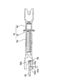
図2に基づいて、シュー間隙調整ストラット31及びシュー間隙の過調整防止機構の構造について説明する。
【0032】
アジャストボルト32は、両端間のフランジ部外周に鋸歯状の外周歯32aを形成し、左方の軸部におねじ32bを螺設していると共に、右方の軸部の両端間に環状の外周溝32cを形成している。
【0033】
全体としてY字状を呈するアジャストナット33は、左方の圧潰平板部33aに形成した切り欠き33bがシューウェブ12とブレーキレバー20(共に図2では図示せず)とを収容して相対回転不能に係合すると共に、底面がブレーキレバー20の内端面に当接している。また、右方に螺設しためねじ33cが前記アジャストボルト32のおねじ32bに螺合している。
【0034】
全体としてY字状を呈するソケット部材34は、右方の圧潰平板部34aに形成した切り欠き34bがシューウェブ17(図2では図示せず)を収容して相対回転不能に係合すると共に、底面がシューウェブ17の内端面に当接している。また、左方の筒部34cの穴が前記アジャストボルト32の右方の軸部に相対回転可能に滑嵌合している。
【0035】
前記アジャストボルト32のフランジ部とソケット部材34の左端面間には、図3に示す二つ折りした温度感応部材35の折り返し重合部が介挿されている。温度感応部材35は、バイメタルや形状記憶合金から成る帯状の板体をプレス加工により一体成型したもので、その折り返し重合部に穿設した穴35a(図3に示す)が前記アジャストボルト32の右方の軸部に遊嵌している。
【0036】
前記ソケット部材34の筒部34cに設けたストッパピン36の先端部がアジャストボルト32の外周溝32cの右方側に所定の隙間δ1を有して遊嵌することで、ソケット部材34とアジャストボルト32の軸方向へ向けた相対的な離間距離を規制するストッパ装置を構成している。
【0037】
次に、前述した構成におけるシュー間隙自動調整作用について説明する。図1において、サービスブレーキ作動によりホイールシンダ5を加圧し、シューリターンスプリング7,8のばね力に抗して両ブレーキシュー10,15を拡開すると、アジャストスプリング38のばね力によりアジャストレバー37を反時計方向に回転すると共に、シュー間隙調整ストラット31を左方へ押動し、ブレーキシュー10及びブレーキレバー20に追従させる。この時、ライニング13,18が摩耗していて、アジャストレバー37の爪部37bの回転量が外周歯32aの歯間ピッチを超えると、外周歯32aの一歯分アジャストボルト32を回転してアジャストナット33から螺出し、シュー間隙調整ストラット31の全長を自動的に伸長してシュー間隙をほぼ一定に保つ。尚、パーキングブレーキ作動時には、シュー間隙調整ストラット31に作用する軸力が増大するから、シュー間隙の自動調整作用は行われない。
【0038】
続いて、シュー間隙の過調整防止作用について説明する。ブレーキが所定の高温になり、これに伴って図外のブレーキドラムが熱膨張すると同時に、温度感応部材35の折り返し重合部の拡開力がシューリターンスプリング7,8のばね力のブレーキシュー10,15に加わる作用力、厳密にはこの作用力とアジャストスプリング38のばね力のソケット部材34に加わる作用力に打ち勝つと、アジャストボルト32とソケット部材34とを離間させながら略V字状に温度変形し、両ブレーキシュー10,15の戻り位置を拡開方向に変位させる。このブレーキが高温になるに連れて大きくなる両ブレーキシュー10,15の外径の変化量が、同条件下におけるブレーキドラムの熱膨張に伴う内径の変化量と略同量になるように設計すれば、ブレーキ非作動時にシュー間隙は増大しない。又、関係する部品のレイアウトの制約等によりそのような設計が困難な場合は、温度感応部材35の温度変形に伴う両ブレーキシュー10,15の外径の変化量が、ブレーキドラムの熱膨張に伴う内径の変化量よりも最初は小さく、やがては同量になり、その後は大きくなるような設計が比較的対応しやすい。この場合は、ストッパピン36が外周溝32cの左端面に当接して相対移動を規制される隙間δ1を設定し、前記アジャストボルト32とソケット部材34とが離間可能な距離を所定の大きさとすることで、温度感応部材35の温度変形に伴う両ブレーキシュー10,15の外径の変化量が、ブレーキドラムの熱膨張に伴う内径の変化量と略同量以内に収まるようにしている。
【0039】
上述した本発明の実施例1によれば、ブレーキが所定の高温に達してブレーキドラムが径方向に膨張しても、温度感応部材35の折り返し重合部がシューリターンスプリング7,8とアジャストスプリング38のばね力によりブレーキシュー10,15に加わる作用力に打ち勝って略V字状に温度変形し、アジャストボルト32とソケット部材34とを離間させ、両ブレーキシュー10,15の戻り位置を拡開方向に変位させてシュー間隙を小さく保つから、その間、自動調整作用を停止してシュー間隙の過調整を防止することに加え、繰り返し使用するサービスブレーキの操作フィーリングの悪化を抑えると共に、迅速なブレーキの効きが確保できる。
【0040】
又、ソケット部材34に固定したストッパピン36がアジャストボルト32に形成した外周溝32cに当接するストッパ装置により、温度感応部材35の温度変形に伴う両ブレーキシュー10,15の外径の変化量が、ブレーキドラムの熱膨張に伴う内径の変化量よりも過度に大きくなることがないので、ブレーキの高温下におけるブレーキシュー10,15の引き摺りを惹起する恐れがない。又、シュー間隙の過調整防止機構を構成する温度感応部材35とストッパピン36とをシュー間隙調整ストラット31に一体に組み付けて組立体として取り扱うことができてブレーキの組立てが容易であるし、ブレーキを分解した際にも部品の組み忘れや紛失する恐れがない。
【0041】
次に、本発明の実施例2について、図4を参照しながら説明する。本例は前述した実施例1のシュー間隙調整ストラット31とシュー間隙の過調整防止機構の構造が相違するものであるから、この相違点のみを中心に説明する。尚、相違する部品については40の位の符号を付して説明する。
【0042】
本例のシュー間隙調整ストラット41は、回転可能なアジャストナット43と、図1における右方のブレーキシュー15に回転不能に当接係合するアジャストボルト42と、図1におけるブレーキレバー20に回転不能に当接係合するソケット部材44から成る。これら三つの部品は、鋸歯状の外周歯43aを形成するアジャストナット43のめねじ43cの右方側から、おねじ42bを螺設するアジャストボルト42の軸部が螺合して貫通し、この突出する軸部にソケット部材44の筒部44cが相対回転可能に、かつ軸線方向に相対移動可能に嵌合している。
【0043】
又、前述した実施例1に示す温度感応部材35の折り返し重合部の穴35aが、アジャストボルト42のおねじ42bを螺設した軸部に遊嵌し、アジャストナット43の左端面とソケット部材44の右端面間に介挿されている。ストッパ装置である短冊状のストッパ部材46の左方側がソケット部材44に2本のリベットで以って固定され、ストッパ部材46の右方側がアジャストナット43を跨いで延出している。ストッパ部材46の先端部に形成した折曲部46aとアジャストナット43の右端面との間に前述した実施例1と同等の隙間δ1を有してシュー間隙の過調整防止機構を構成している。
【0044】
次に、本発明の実施例3について、図5,図6を参照しながら説明する。本例は、前述した実施例1に対しシュー間隙の過調整防止機構の構造のみが相違するものであるから、この相違点を中心に説明するに留める。尚、相違する部品については50の位の符号を付して説明し、同一部品については同一の符号を付してその説明を省略する。
【0045】
本例は、アジャストボルト52、ソケット部材54と連携してシュー間隙調整ストラット51を構成するアジャストナット53とブレーキレバー50との間にシュー間隙の過調整防止機構を具備したものである。この構造を図6に基づいて説明すると、後述する温度感応部材55の折り返し重合部をアジャストナット53の圧潰平板部53aに形成した切り欠き53bの底面とブレーキレバー50の内端面間に介挿し、又、切り欠き53b部の下方側の左端部に形成した鉤状部53dがブレーキレバー50に穿設した穴50dの右方側に、前述した実施例1と同等の隙間δ1を有し遊嵌している。
【0046】
温度感応部材55は、二つ折りした一方の脚部55bがアジャストナット53の切り欠き53bの底面に当接して圧潰平板部53aを挟持するよう略C字状に形成され、他方の脚部55cに折曲形成した二つの係止部55d,55dがブレーキレバー50の裏面に係合している。尚、温度感応部材55の取着対象はブレーキレバー50でもよいし、又、他方の脚部55cに形成した係止部55d,55dは、アジャストナット53の軸心に対する回転方向の遊びを小さく抑える効果を発揮するが必須ではない。
【0047】
前述した構成において、温度感応部材55が所定の温度に達すると略V字状に拡開し、アジャストナット53とブレーキレバー50とを離間させる。この最大移動距離はアジャストナット53の鉤状部53dがブレーキレバー50の穴50dに当接して規制される隙間δ1に相当し、そのシュー間隙の過調整防止作用の効果については前述した実施例1と同じであるから説明を省略する。
【0048】
次に、本発明の実施例4について、図7〜図10を参照しながら説明する。本例のドラムブレーキは、前述した実施例1に対しワンショット形のシュー間隙自動調整装置を具備するドラムブレーキを示し、これにシュー間隙の過調整防止機構を付設したものであるから、前述した実施例1と同一機能の部品及び部位については100の位の符号を付して説明する。
【0049】
すなわち、102はバックプレート,103と104は一対のシューホールド機構,105はホイールシリンダ,106はアンカーブロック,107と108は一対のシューリターンスプリング,110と115は一対のブレーキシュー,120はブレーキレバー,121はブレーキレバー120を枢支するピン,122はブレーキケーブル,135は温度感応部材,136はストッパピンである。これら部品の機能は、実施例1と同じであるからその説明を省略する。
【0050】
図7におけるホイールシリンダ105に隣接して、ブレーキシュー110のシューウェブ112とブレーキレバー120間にブレーキシュー110と115の後退規制装置としてのシュー間隙調整ストラット161が掛け渡されている。このシュー間隙調整ストラット161により、アンカーブロック106との当接点を支点とした一対のブレーキシュー110,115の戻り位置が規制され、シュー間隙を決めている。
【0051】
前記シュー間隙調整ストラット161は板状のストラット本体162、ベルクランク状のアジャストレバー163、このアジャストレバー163をストラット本体162に枢着するピン164及び第二スプリング165から成り、これに第一スプリング166を付加してシュー間隙自動調整装置160を構成している。
【0052】
ストラット本体162は、その図8における右方に形成した切り欠き162aがブレーキレバー120とシューウェブ117を収容し、切り欠き162aの底面がブレーキレバー120に当接してブレーキシュー115の戻り位置を規制している。又、ストラット本体162の両端間の左方寄りには小刻みな歯162bが刻設され、この図8における上方側の部分は図7に示すように略板厚分の段差を設けて折曲され、左方側に延伸している。
【0053】
アジャストレバー163の基部163aはストラット本体162の左方端部に回転可能に、且つストラット本体162の長手方向の板面に沿って可動的に、言い換えると、ブレーキシュー110の拡開方向に移動可能にピン164で以って枢支されており、ストラット本体162とピン164間に張設した第二スプリング165の付勢力により、一方の腕部163bの円弧形端面に刻設した小刻みな歯163cが前記ストラット本体162の小刻みな歯162bに噛み合っている。又、他方の腕部163dはカム部163eを有し、このカム部163eがシューウェブ112に形成した矩形穴112aのブレーキ外方側に当接してブレーキシュー110の戻り位置を規制すると共に、ブレーキ内方側に所定の隙間δ5を有して嵌入している。
【0054】
シューウェブ117とストラット本体162間に張設した第一スプリング166のばね力は第二スプリング165のばね力よりも大きく設定してある。
【0055】
ブレーキレバー120の自由端部120bに近いブレーキ内方側に、シューウェブ117の内端面に平行に対面する対向片120dが図9に示すように折曲形成されている。前記対向片120dの内面とシューウェブ117の内端面間には、図10に示す二つ折りした温度感応部材135の折り返し重合部とストッパピン136の頭部136bが介挿され、ブレーキレバー120の戻り位置を規制している。本例の温度感応部材135は、一方の脚部135bの先端部に形成した略C字状部が対向片120dを抱持して弾着され、ストッパピン136の頭部136bの端面がシューウェブ117の内端面に当接すると共に、細径胴部136cが温度感応部材135の折り返し重合部と対向片120dを貫通し、この対向片120dの外面と細径胴部136cの端部に止着したワッシャ167との間に隙間δ2を形成している。
【0056】
続いて、前述した構成におけるシュー間隙自動調整作用について、図7,図8を参照しながら説明する。サービスブレーキ作動により両ブレーキシュー110,115が拡開すると、一対のブレーキシュー110,115の拡開量が、シューウェブ112の矩形穴112aとアジャストレバー163のカム部163eとの隙間δ5に加え、アジャストレバー163の小刻みな歯163cとストラット本体162の小刻みな歯162bとの噛合高さを越えるまでは、ストラット本体162は第一スプリング166のばね力によりブレーキシュー115及びブレーキレバー120に追従し、アジャストレバー163は第二スプリング165のばね力に抗してブレーキシュー110に追従する。そして、ライニング113,118が摩耗して一対のブレーキシュー110,115の拡開量が、前記した隙間δ5と噛合高さの合計を越えると、アジャストレバー163が回転して小刻みな歯163cの1歯相当分だけ、シューウェブ112の矩形穴112aに当接するカム部163eのカム面の当接点を変位させる。これにより、シューウェブ112の矩形穴112aの内縁を支持するカム部163eのカム面位置からブレーキレバー120を支持するストラット本体162の切り欠き162aの底面までの距離L1を自動的に長くし、シュー間隙をほぼ一定に保つ。
【0057】
続いて、シュー間隙の過調整防止作用について説明する。ブレーキが所定の高温になり、これに伴って図外のブレーキドラムが熱膨張すると同時に、温度感応部材135の折り返し重合部の拡開力がシューリターンスプリング107,108のばね力によりブレーキシュー110,115に加わる作用力、厳密にはこの作用力と第一スプリング166のばね力のストラット本体162に加わる作用力に打ち勝ち、略V字状に温度変形しながらブレーキレバー120を前進させ、前述した実施例1と同様、両ブレーキシュー110,115の戻り位置を拡開方向に変位させる。その結果、ブレーキの高温下におけるブレーキ非作動時にシュー間隙は増大しない。尚、この時に、シューリターンスプリング107,108と第一スプリング166のばね力に抗する温度感応部材135の拡開力は、図7において、ピン121の中心を通る水平線からブレーキレバー120がストラット本体162を押圧する点を通る水平線までの垂直な距離L2を、ピン121の中心を通る水平線から温度感応部材135がブレーキレバー120を付勢する作用点を通る水平線までの垂直な距離L1で除した値、即ち、L2/L1に前記のブレーキシュー110,115に加わる作用力を乗じた値より大きければよい。その結果、例えば温度感応部材135の板厚を薄くできる等、重量を大幅に軽減できるので安価にできる。又、ブレーキが所定の高温時における温度感応部材135の温度変形に伴ってブレーキレバー120が前進する最大移動距離は、対向片120dとワッシャ167との隙間δ2で決まり、この時のブレーキシュー110,115の外径の変化量が、同条件下における図外のブレーキドラムの内径の変化量と略同量になるよう設定してあるから、前述した実施例1と同等の効果が得られる。
【0058】
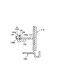
次に、本発明の実施例5について、図11,図12を参照しながら説明する。図11は図7のXI−XI断面に相当する構造図を示すもので、前述した本発明の実施例4と同一機能の部品及び部位については100の位を200の位に変えて説明する。
【0059】
図11におけるバックプレート202の左方にはブレーキ外方側に向けてパイプ部材209が固定されている。パーキングブレーキ用のブレーキケーブル222はインナーケーブル223とこれを保護するアウターケーシング225等から構成されている。アウターケーシング225の一端部に固定したケーシングキャップ226がパイプ部材209に嵌入して線ばねクリップ268で以って取着され、アウターケーシング225内を摺動可能なインナーケーブル223は、その一端部がブレーキレバー220の自由端部220bに形成した溝内に嵌入すると共に、一端部に固定した端末金具224が温度感応部材235の折り返し重合部とL字形のストッパ部材236の一方片236dを介して自由端部220bの右端面側に掛止されている。一方、ブレーキケーブル222の図外の他端部と図示する部分の間は車体に沿い適宜湾曲して配索され、アウターケーシング225の図外の他端部が車両の不動部に固定されると共に、インナーケーブル223の図外の他端部が車室内の操作レバーに接続されていて、ブレーキレバー220はインナーケーブル223の端末金具224により戻り位置が規制されている。又、ブレーキレバー220の自由端部220bと温度感応部材235間に介在する前記ストッパ部材236の一方片236dの折曲部から他方片236eにかけて形成した四角穴236f内に、温度感応部材235の折り返し重合部の先端部が右方側に隙間δ3を有して嵌入している。
【0060】
上述した構成におけるパーキングブレーキ作動は、インナーケーブル223を牽引するとブレーキレバー220が図7におけるブレーキレバー120と同様に時計方向に回転し、図7におけるシュー間隙調整ストラット161と同様のシュー間隙調整ストラット(図示せず)がブレーキシュー210を押圧すると共に、図7におけるピン121と同様のピンがブレーキシュー215を押圧して夫々拡開させる。
【0061】
前述した構成において、温度感応部材235が所定の温度に達すると略V字状に拡開し、ブレーキレバー220の自由端部220bを図11における左方に移動させるから、シュー間隙が小さくなり自動調整作用は停止する。本例における温度感応部材235の取着位置でのレバー比は、前述した本発明の実施例4に比べて大きくなり、それに応じて温度感応部材235の拡開力を小さくすることができる。又、ブレーキレバー220が前進する最大移動距離は、温度感応部材235と四角穴236fの内縁との隙間δ3により決まり、前述した実施例1と同等の効果が得られる。
【0062】
尚、本発明は、前述した実施例1〜実施例5の構造に限定されるものではなく、例えば、パーキングブレーキ機構(ブレーキレバー20,120,220とブレーキケーブル22,122,222等)は必須ではないし、又、実施例では、レバー部材としてのブレーキレバーを具備するドラムブレーキについて説明したが、これに代えて、バックプレートの裏側からボルト部材を螺合して突出させ、その突出端部で以って図1や図7におけるブレーキレバー20や120に該当する部材の自由端部の戻り位置を規制するよう支持し、この支持手段を解除することにより一対のブレーキシューの外径を縮小してブレーキドラムの取り外しを容易にする、所謂ブレーキシュー外径の縮径レバーでもよい。前記支持手段はこれに限定されるものではなく、要はブレーキの外部から手動で以って縮径レバーの戻りを可能にする構造であればよい。更に、シュー間隙自動調整機構とシュー間隙の過調整防止機構とを適宜組替えて用いることができるし、シュー間隙の過調整防止機構としての温度感応部材が被取着部材の軸部に嵌合する構造の場合には、温度感応部材の穴径と被取着部材の軸径との隙間を精密に加工しておき、温度感応部材がV字状に拡開した時に、その穴の対角部が軸部に当接して拡開量を規制するストッパ装置とすることも可能である等々、幾多の変更が可能であることは明らかである。
【0063】
【発明の効果】
本発明は、以上説明したように構成されているので、以下に記載するような効果のうち、少なくとも何れか一つの効果を奏する。
<イ> ブレーキが所定の高温に達してブレーキドラムが径方向に膨張しても、温度感応部材がブレーキシューを戻り位置に戻す作用力(シューリターンスプリングのばね力等)に打ち勝って温度変形し、ブレーキの非作動時における一対のブレーキシューの戻り位置を拡開方向に変位させてシュー間隙を小さく抑えるから、シュー間隙の自動調整作用を停止して過調整を防止することに加え、繰り返し使用するサービスブレーキの作動ストロークが大きくなることによる操作フィーリングの悪化を抑えられ、迅速なブレーキの効きを確保できる。
【0064】
<ロ> ブレーキが高温になるに連れて大きくなる温度感応部材の温度変形に伴って大きくなるブレーキシューの外径の変化量が、同条件下におけるブレーキドラムの熱膨張に伴って大きくなるブレーキドラムの内径の変化量と略同量になるように構成すれば、ブレーキの高温時におけるブレーキシューの引き摺りを確実に防止できる。
【0065】
<ハ> ブレーキが所定の高温時に、温度感応部材の温度変形に伴うブレーキシューの外径の変化量が、同条件下におけるブレーキドラムの熱膨張に伴う内径の変化量よりも過度に大きくなることを防止するストッパ装置を付設すれば、ブレーキが所定の高温時におけるブレーキシューの引き摺りを確実に防止できる。
【0066】
<ニ> シュー間隙の過調整防止機構を構成する温度感応部材とストッパ装置は、ドラムブレーキの構成部品に一体に組み付けて組立体として取り扱うことができるので、ブレーキの組立てが容易であるし、ブレーキを分解した際にも部品の組み忘れや紛失の恐れがない。
【0067】
<ホ> ブレーキシューの戻り位置を規制する後退規制装置の一端部が、レバー部材を介して一方のブレーキシューを支持するドラムブレーキにも適用でき、レバー部材はパーキングブレーキ用のブレーキレバーや一対のブレーキシューの外径をブレーキ外部から手動で縮小できる縮径レバーでよく、種々の形式のドラムブレーキに採用できる。
【0068】
<へ> シュー間隙の過調整防止機構をレバー部材の自由端部側、具体的にはレバー部材のシュー間隙調整ストラットとの当接部から自由端部までの間、或いはパーキングブレーキ用のブレーキレバーのブレーキケーブルとの接続部に配設することにより、温度感応部材の拡開力を、その配設位置でのレバー比で按分した分だけ弱く設定できるから、板厚を薄くしたり、幅を狭めたりして重量を軽くすることができて小型化が可能であり、低コスト化が図れる。
【0069】
<ト> ねじ結合部を自動的に相対変位させるインクリメンタル形のシュー間隙自動調整装置、或いは、小刻みな歯の噛合部を自動的に相対変位させるワンショット形にシュー間隙自動調整装置にも適用できて汎用性に富む。
【図面の簡単な説明】
【図1】 本発明の実施例1に係わるドラムブレーキの正面図
【図2】 図1のシュー間隙調整ストラットとシュー間隙過調整防止装置との組立体の要部を断面した図
【図3】 図1の温度感応部材を拡大した斜視図
【図4】 本発明の実施例2に係わり、図1に相当する図
【図5】 本発明の実施例3に係わるドラムブレーキの正面図
【図6】 図5のVI−VI断面図
【図7】 本発明の実施例4に係わるドラムブレーキの正面図
【図8】 図7のXIII−XIII断面図
【図9】 図7のIX−IX断面図
【図10】 図7の温度感応部材を拡大した斜視図
【図11】 本発明の実施例5に係わり、図7のXI−XI断面に相当する構造図
【図12】 図11のXII−XII矢斜図
【符号の説明】
5,105,205 ホイールシリンダ
7,8,107,108 シューリターンスプリング
10,15,110,115,210,215 ブレーキシュー
20,50,120,220 ブレーキレバー
22,122,222 ブレーキケーブル
30,160 シュー間隙自動調整装置
31,41,51,161 シュー間隙調整ストラット
32,42,52 アジャストボルト
33,43,53 アジャストナット
34,44,54 ソケット部材
35,55,135,235 温度感応部材
36,136 ストッパピン
37,163 アジャストレバー
46,236 ストッパ部材
162 ストラット本体[0001]
BACKGROUND OF THE INVENTION
The present invention relates to a drum brake equipped with an automatic shoe gap adjusting device, and more specifically, an automatic adjustment action of a gap between a brake drum and a brake shoe (hereinafter referred to as a shoe gap) when the brake reaches a predetermined high temperature. The present invention relates to an over-adjustment prevention mechanism that stops the operation.
[0002]
[Prior art]
In general, the drum brake is provided with an automatic shoe clearance adjusting device that compensates for wear of the brake shoe lining and keeps the shoe clearance constant. When the service brake is repeatedly used on a long downhill or the like, the shoe gap temporarily increases by the amount that the brake drum becomes hot and expands in the radial direction. Under such circumstances, in a drum brake configuration in which it is assumed that the lining is worn and the automatic adjustment of the shoe clearance is continued, the shoe clearance is reduced when the brake drum is cooled to room temperature and returned to its original size. This causes a problem that drag becomes too narrow. In order to avoid this drag, if the shoe gap is set large in advance when normal brakes are used (when the predetermined high temperature is not reached), drag due to excessive adjustment of the shoe gap can be prevented, but the brake stroke becomes large. This causes problems such as deterioration in operation feeling and delay in effectiveness.
[0003]
Japanese Patent Publication No. 58-49739 discloses a drum brake having a shoe gap over-adjustment prevention mechanism that solves the above-described problems. The pair of brake shoes in this drum brake has a return position with the contact point with the anchor by the spring force of the shoe return spring as a fulcrum, and is spanned between both brake shoes adjacent to the wheel cylinder for service brakes. It is regulated by a shoe clearance adjusting strut as a backward regulating device.
[0004]
The shoe gap adjusting strut includes a non-rotatable screw member (screw rod), a nut member (nut) that is screw-engaged with the male screw member, and a non-rotatable sleeve member (cylindrical cylinder) that is slidably fitted to the male screw member ), And an adjustment lever (arm) and an adjustment spring (claw spring) for rotating the nut member are attached thereto, thereby forming an incremental shoe gap automatic adjusting device. Further, a shoe gap over-adjustment preventing mechanism is provided between two members that are slidably fitted so as to be separable in the axial direction of the shoe gap adjusting strut (in the above-mentioned publication, between a screw engaging body composed of a nut member and a bolt member and a sleeve member). A temperature sensitive member (bimetal strip) that is a constituent element of is inserted.
[0005]
This temperature-sensitive member is inserted between the sleeve member and the nut member by passing the screw member through the folded overlap portion, and when the brake reaches a predetermined temperature, strictly speaking, the temperature-sensitive member is When the service brake is actuated against the spring force of the shoe return spring when the temperature is reached, the folded portion of the temperature sensitive member expands to separate the sleeve member and the screw engagement body, This screw engagement body By causing the brake member to follow the expansion of one brake shoe and causing the sleeve member to follow the expansion of the other brake shoe, the automatic adjustment action of the shoe gap is stopped to prevent over-adjustment.
[0006]
The above-described shoe gap over-adjustment prevention mechanism cannot be applied to an automatic shoe gap adjusting device (for example, one-shot type) other than the incremental type, and Japanese Patent Application Laid-Open No. 2002-106620 has been considered to solve this problem. It is invention described in. The shoe gap over-adjustment prevention mechanism provided in this drum brake has a temperature sensitive member made of bimetal or shape memory alloy interposed between the shoe gap adjusting strut and the brake shoe or between the shoe gap adjusting strut and the brake lever. . According to this configuration, since it can be applied to a one-shot type shoe clearance automatic adjusting device, it is versatile.
[0007]
A typical one-shot type shoe clearance automatic adjusting device includes a strut body, a bell crank-shaped adjustment lever, a shoe clearance adjustment strut comprising a pin and a second spring for pivotally attaching the adjustment lever to the strut body, and a strut body. It is composed of a first spring stretched between one brake shoe, and when the amount of expansion of the pair of brake shoes exceeds a predetermined value when the service brake is activated, the strut body is moved to one brake by the spring force of the first spring. While following the shoe and brake lever, the other brake shoe acts on the adjust lever, and the engagement position of the adjust lever to the strut body is displaced to extend the overall length of the shoe gap adjusting strut, and the shoe gap is automatically adjusted. Configured to adjust.
[0008]
The shoe gap over-adjustment prevention mechanism is a service in which the folded part of the temperature-sensitive member folded in half is inserted between the strut body and the brake lever, and the brake drum is hot and the temperature-sensitive member has reached the specified temperature. When the brake is operated, the folding overlap part of the temperature sensitive member expands against the spring force of the first spring, causing the shoe gap adjustment strut to follow the other brake shoe and stops the automatic adjustment of the shoe gap. To prevent over-adjustment.
[0009]
[Problems to be solved by the invention]
In the aforementioned shoe gap over-adjustment prevention mechanism, as described below, Task was there.
[0010]
<B> While the brake drum expands in the radial direction at high temperatures, the automatic adjustment of the shoe gap is stopped, and when the brake is not in operation, the pair of brake shoes is heated by the spring force of the shoe return spring. Since the folded overlap portion of the sensitive member is returned to the compressed position, the shoe gap is increased by the amount of expansion of the brake drum. As a result, the operating stroke of the service brake that is repeatedly used increases, resulting in a deterioration of the operational feeling or a delay in the braking effect.
[0011]
<B> In the above-described incremental type shoe clearance automatic adjusting device, the sleeve member and the temperature sensitive member can be detached from the external thread member, so that the handling of the shoe clearance adjusting strut and the assembly of the brake are troublesome. Further, when the brake is disassembled, the temperature sensitive member may be forgotten or lost.
[0012]
The present invention has been made in view of the above problems, and prevents over-adjustment of the shoe gap when the brake is hot, and suppresses the shoe gap when the brake is not in operation, thereby reducing the operation feeling of the service brake. The purpose of the present invention is to provide a drum brake that can prevent the deterioration of the brake and ensure the effectiveness of a quick brake.
[0013]
[Means for Solving the Problems]
In order to achieve the above-described object, in the drum brake according to the present invention, a service brake actuator is disposed between adjacent one end portions of a pair of brake shoes, and the return positions of both brake shoes are regulated so as to restrict both brake shoes. When a reverse regulating device for determining a shoe gap with respect to the brake drum is passed between the two brake shoes adjacent to the actuator and the spread amount of both the brake shoes exceeds a predetermined value when the service brake is operated, An automatic shoe clearance adjusting device is provided that automatically displaces the contact position of the reverse regulating device with the brake shoe and displaces the return position of the brake shoe in the brake shoe expansion direction. With A temperature-sensitive member is provided to prevent over-adjustment of the shoe clearance by energizing the retraction restricting device in a direction to stop the automatic adjustment of the shoe clearance at a predetermined temperature. In the drum brake The acting force in the expanding direction of the two brake shoes accompanying the temperature deformation of the temperature sensitive member is larger than the acting force for returning the two brake shoes to the return position. When the service brake is inactive, both brake shoes should be expanded. It is a thing.
[0014]
Also, due to the temperature deformation of the temperature sensitive member that increases as the brake becomes hot With it The change in the outer diameter of both brake shoes contributes to the thermal expansion of the brake drum under the same conditions. Brake drum that grows with it It is good to comprise so that it may become substantially the same amount as the variation | change_quantity of an internal diameter.
[0015]
Also, when the brake is at a predetermined high temperature , Change in outer diameter of both brake shoes due to temperature deformation of temperature sensitive member When , The amount of change in the inner diameter accompanying the thermal expansion of the brake drum under the same conditions But It is preferable to provide stopper means for restricting the amount to be substantially the same.
[0016]
Further, a lever member is disposed in a direction intersecting with the reverse regulating device, and is pivotally supported on either one of the brake shoes to form a folded overlap portion on the temperature sensitive member. The folded overlap portion is formed as a lever member. It is preferable to provide a stopper means that is interposed between the retraction restricting device and restricts the amount of expansion of the folded overlapping portion.
[0017]
In addition, a lever member is disposed in a direction intersecting with the retraction restricting device, and is pivotally supported on one of the brake shoes so as to be rotatable. One end of the retreat restricting device is interposed between the pivot portion and the free end of the lever member. And the rotation return position on the free end side of the lever member is regulated by the support member, and the folded overlap portion is formed on the temperature sensitive member, and the folded overlap portion is connected to the free end side of the lever member. A stopper device that is interposed between the support members and regulates the amount of expansion of the folded overlap portion may be provided.
[0018]
Further, the retraction restricting device has a screw coupling mechanism comprising a rotatable member integrally forming the outer peripheral teeth and a non-rotatable member screwed to the rotatable member, and the expansion amounts of both brake shoes are predetermined. If the value exceeds the value, the member forming the outer peripheral teeth may rotate and relatively displace in the axial direction, and the return position of the brake shoe may be automatically displaced in the expanding direction. A folding overlap portion of the temperature sensitive member is interposed between the member to be formed and a member that is rotatable relative to and separate from the member to be formed, and the amount of expansion of the overlap overlap portion is increased. You may attach the stopper apparatus to regulate.
[0019]
In addition, the retraction restricting device has a small tooth meshing mechanism that allows the adjustment lever to rotate in one direction. When the expansion amount of both brake shoes exceeds a predetermined shoe clearance, the adjustment lever rotates. It is preferable that the meshing position of the teeth is displaced little by little and the return position of the brake shoe is automatically displaced in the expanding direction.
[0020]
According to the drum brake configured as described above, when the brake drum becomes hot, it resists the spring force of the shoe return spring by the acting force accompanying the temperature deformation of the temperature sensitive member that stops the automatic adjustment of the shoe gap. Since the return position of the pair of brake shoes is regulated, the shoe gap can be kept small when the brake is not in operation, and the deterioration of the operation feeling due to the increase in the service brake operating stroke can be suppressed, and the speed can be reduced. The effectiveness of the brake can be secured.
[0021]
Also, the amount of change in the outer diameter of both brake shoes accompanying the temperature deformation of the temperature-sensitive member that increases as the brake becomes hot is substantially the same as the amount of change in the inner diameter accompanying thermal expansion of the brake drum under the same conditions. If the amount is configured, the brake shoe can be reliably prevented from being dragged when the brake is at a high temperature.
[0022]
Further, when the brake is at a predetermined high temperature, the amount of change in the outer diameter of both brake shoes accompanying the temperature deformation of the temperature sensitive member is substantially the same as the amount of change in the inner diameter accompanying thermal expansion of the brake drum under the same conditions. If the stopper means for restricting the brake is provided, the brake shoe can be reliably prevented from being dragged when the brake is at a predetermined high temperature.
[0023]
It can also be applied to a drum brake in which one end portion of the reverse regulating device supports one brake shoe via a lever member, and the lever member allows the outer diameter of a brake lever for a parking brake or a pair of brake shoes to be externally provided from the brake. A diameter-reducing lever that can be reduced manually is sufficient, and can be used for various types of drum brakes.
[0024]
It can also be applied to an incremental type shoe clearance automatic adjustment device that automatically displaces screw joints, or a one-shot type shoe clearance automatic adjustment device that automatically displaces the meshing portions of small teeth. Rich in versatility.
[0025]
DETAILED DESCRIPTION OF THE INVENTION
Hereinafter, an example of the drum brake according to the present invention will be described.
[0026]
First, Embodiment 1 of the present invention will be described with reference to FIGS. The present example is a drum brake having an incremental shoe gap automatic adjusting device and a forward pull type parking brake device, and a pair of opposing
[0027]
In the
[0028]
Adjacent to the
[0029]
The shoe
[0030]
The
[0031]
The structure of the shoe
[0032]
The
[0033]
The
[0034]
The
[0035]
Between the flange portion of the adjusting
[0036]
The tip of the
[0037]
Next, the shoe gap automatic adjusting action in the above-described configuration will be described. In FIG. 1, when the
[0038]
Next, the over-adjustment preventing action of the shoe gap will be described. As the brake reaches a predetermined high temperature, a brake drum (not shown) is thermally expanded, and at the same time, the expansion force of the folded overlapping portion of the temperature
[0039]
According to the above-described first embodiment of the present invention, even when the brake reaches a predetermined high temperature and the brake drum expands in the radial direction, the folded overlapping portion of the temperature
[0040]
Further, the stopper device in which the
[0041]
Next, a second embodiment of the present invention will be described with reference to FIG. In this example, the structure of the shoe
[0042]
The shoe
[0043]
Further, the
[0044]
Next,
[0045]
In this example, a shoe gap over-adjustment preventing mechanism is provided between the adjusting
[0046]
The temperature
[0047]
In the configuration described above, when the temperature
[0048]
Next, a fourth embodiment of the present invention will be described with reference to FIGS. The drum brake of this example is a drum brake having a one-shot type shoe gap automatic adjusting device as compared with the first embodiment described above, and is provided with a shoe gap over-adjustment preventing mechanism. Parts and parts having the same functions as those in the first embodiment will be described with reference numerals of 100.
[0049]
That is, 102 is a back plate, 103 and 104 are a pair of shoe hold mechanisms, 105 is a wheel cylinder, 106 is an anchor block, 107 and 108 are a pair of shoe return springs, 110 and 115 are a pair of brake shoes, and 120 is a brake lever. , 121 is a pin for pivotally supporting the
[0050]
Adjacent to the
[0051]
The shoe
[0052]
In the
[0053]
The
[0054]
The spring force of the
[0055]
On the inner side of the brake near the
[0056]
Next, the shoe gap automatic adjusting action in the above-described configuration will be described with reference to FIGS. When both
[0057]
Next, the over-adjustment preventing action of the shoe gap will be described. As the brake reaches a predetermined high temperature, a brake drum (not shown) is thermally expanded. At the same time, the expansion force of the folded overlapping portion of the temperature
[0058]
Next, a fifth embodiment of the present invention will be described with reference to FIGS. FIG. 11 is a structural diagram corresponding to the XI-XI cross section of FIG. 7. The parts and parts having the same functions as those of the fourth embodiment of the present invention described above will be described by changing the place of 100 to the place of 200.
[0059]
A
[0060]
In the parking brake operation in the configuration described above, when the
[0061]
In the above-described configuration, when the temperature
[0062]
In addition, this invention is not limited to the structure of Example 1-5 mentioned above, For example, a parking brake mechanism (brake lever 20,120,220 and brake cables 22,122,222 etc.) is essential. However, in the embodiment, the drum brake having a brake lever as a lever member has been described, but instead, a bolt member is screwed and projected from the back side of the back plate. Accordingly, it supports to restrict the return position of the free end portion of the member corresponding to the
[0063]
【The invention's effect】
Since the present invention is configured as described above, it exhibits at least one of the effects described below.
<A> When the brake reaches a predetermined high temperature, Is Even if it expands in the radial direction, the temperature-sensitive member overcomes the action force (such as the spring force of the shoe return spring) that returns the brake shoe to the return position and deforms in temperature, and the return position of the pair of brake shoes when the brake is not operating Since the shoe gap is kept small by displacing the shoe in the expanding direction, the automatic adjustment of the shoe gap is stopped to prevent over-adjustment, and the operation feeling of the service brake that is repeatedly used increases. To prevent the deterioration of the brakes and ensure quick braking wear .
[0064]
<B> For temperature deformation of temperature-sensitive members that increase as the brake temperature rises With it The amount of change in the outer diameter of the brake shoe contributes to the thermal expansion of the brake drum under the same conditions. Of the brake drum If it is configured to be substantially the same as the amount of change in the inner diameter, the brake shoe can be reliably prevented from being dragged when the brake is hot.
[0065]
<C> When the brake is at a predetermined high temperature , If a stopper device for preventing the change amount of the outer diameter of the brake shoe accompanying the temperature deformation of the temperature sensitive member from becoming excessively larger than the change amount of the inner diameter accompanying the thermal expansion of the brake drum under the same condition, The brake shoe can be reliably prevented from being dragged when the brake is at a predetermined high temperature.
[0066]
<D> The temperature-sensitive member and stopper device that constitute the shoe gap over-adjustment prevention mechanism can be assembled as an integrated assembly with the drum brake components, making it easy to assemble the brake. There is no risk of forgetting or losing parts when disassembling.
[0067]
<E> One end of the reverse regulating device that regulates the return position of the brake shoe can also be applied to a drum brake that supports one brake shoe via a lever member. The lever member is a brake lever for a parking brake or a pair of A diameter-reducing lever that can manually reduce the outer diameter of the brake shoe from the outside of the brake may be used, and can be adopted for various types of drum brakes.
[0068]
<To> The shoe gap over-adjustment prevention mechanism is provided on the free end side of the lever member, specifically, between the contact portion of the lever member with the shoe gap adjusting strut and the free end, or a brake lever for a parking brake. Since the expansion force of the temperature sensitive member can be set to be weaker by the ratio of the lever at the installation position, the plate thickness can be reduced or the width can be reduced. The weight can be reduced by narrowing, and the size can be reduced and the cost can be reduced.
[0069]
<G> Incremental shoe clearance automatic adjustment device that automatically displaces screw joints, or one-shot type automatic shoe clearance adjustment device that automatically displaces small tooth meshing portions automatically And versatile.
[Brief description of the drawings]
FIG. 1 is a front view of a drum brake according to a first embodiment of the present invention.
FIG. 2 is a cross-sectional view of the main part of the assembly of the shoe gap adjusting strut and the shoe gap over-adjustment preventing device shown in FIG.
FIG. 3 is an enlarged perspective view of the temperature sensitive member of FIG.
FIG. 4 relates to Embodiment 2 of the present invention and corresponds to FIG.
FIG. 5 is a front view of a drum brake according to a third embodiment of the present invention.
6 is a sectional view taken along line VI-VI in FIG.
FIG. 7 is a front view of a drum brake according to a fourth embodiment of the present invention.
8 is a sectional view taken along line XIII-XIII in FIG.
9 is a cross-sectional view taken along the line IX-IX in FIG.
10 is an enlarged perspective view of the temperature sensitive member of FIG.
FIG. 11 relates to
FIG. 12 is an XII-XII arrow oblique view of FIG.
[Explanation of symbols]
5,105,205 Wheel cylinder
7, 8, 107, 108 Shoe return spring
10, 15, 110, 115, 210, 215 Brake shoe
20, 50, 120, 220 Brake lever
22, 122, 222 Brake cable
30,160 Shoe gap automatic adjustment device
31, 41, 51, 161 Shoe gap adjusting strut
32, 42, 52 Adjustment bolt
33, 43, 53 Adjustment nut
34, 44, 54 Socket member
35, 55, 135, 235 Temperature sensitive member
36,136 Stopper pin
37,163 Adjust lever
46,236 Stopper member
162 Strut body
Claims (9)
この温度感応部材の温度変形に伴う前記両ブレーキシューの拡開方向への作用力を、前記両ブレーキシューを前記戻り位置に戻す作用力より大きくし、サービスブレーキ非作動時において、前記両ブレーキシューを拡開させることを特徴とする、
ドラムブレーキ。A service brake actuator is arranged between adjacent one ends of a pair of brake shoes, and a reverse regulating device for regulating the return position of both brake shoes and determining the shoe gap between the brake shoes of the brake shoes is provided on both brake shoes. When the extension amount of the two brake shoes exceeds a predetermined value when the service brake is operated, the contact position of the reverse regulating device with the brake shoe is automatically displaced. urging together, the backward movement limiting device in a direction to stop the automatic shoe clearance adjustment action when a predetermined temperature is allowed to comprise a automatic shoe clearance adjustment device for displacing the expansion direction of the brake shoe return position of the brake shoe drum brake odor was attached a temperature sensitive member to prevent over adjustment of the shoe clearance by ,
The acting force in the expanding direction of the two brake shoes accompanying the temperature deformation of the temperature sensitive member is made larger than the acting force for returning the two brake shoes to the return position, and the two brake shoes are operated when the service brake is not operated. It is characterized by expanding the
Drum brake.
Priority Applications (1)
| Application Number | Priority Date | Filing Date | Title |
|---|---|---|---|
| JP2002171775A JP4005852B2 (en) | 2002-06-12 | 2002-06-12 | Drum brake |
Applications Claiming Priority (1)
| Application Number | Priority Date | Filing Date | Title |
|---|---|---|---|
| JP2002171775A JP4005852B2 (en) | 2002-06-12 | 2002-06-12 | Drum brake |
Publications (3)
| Publication Number | Publication Date |
|---|---|
| JP2004019687A JP2004019687A (en) | 2004-01-22 |
| JP2004019687A5 JP2004019687A5 (en) | 2005-10-27 |
| JP4005852B2 true JP4005852B2 (en) | 2007-11-14 |
Family
ID=31171543
Family Applications (1)
| Application Number | Title | Priority Date | Filing Date |
|---|---|---|---|
| JP2002171775A Expired - Fee Related JP4005852B2 (en) | 2002-06-12 | 2002-06-12 | Drum brake |
Country Status (1)
| Country | Link |
|---|---|
| JP (1) | JP4005852B2 (en) |
-
2002
- 2002-06-12 JP JP2002171775A patent/JP4005852B2/en not_active Expired - Fee Related
Also Published As
| Publication number | Publication date |
|---|---|
| JP2004019687A (en) | 2004-01-22 |
Similar Documents
| Publication | Publication Date | Title |
|---|---|---|
| US4148380A (en) | Automatic shoe clearance adjusting device in shoe drum brake | |
| JP3953348B2 (en) | Drum brake | |
| JPS5849739B2 (en) | Shudrum brake | |
| US6328141B1 (en) | Drum brake device with automatic shoe clearance adjustment device | |
| JP3728574B2 (en) | Automatic brake clearance adjustment device for drum brakes | |
| JP4505121B2 (en) | Drum brake shoe gap over-adjustment prevention device | |
| JP4005852B2 (en) | Drum brake | |
| JPH0536653B2 (en) | ||
| US20060219493A1 (en) | Automatic shoe clearance adjustment apparatus | |
| US4533024A (en) | Automatic adjusting device for a brake | |
| CZ120093A3 (en) | Automatic adjusting device for a brake, particularly for a drum brake | |
| JPH08338463A (en) | Automatic clearance adjuster of dram brake | |
| JPH0874901A (en) | Automatic clearance adjusting device for drum brake | |
| JPH08105472A (en) | Drum brake with automatic shoe gap adjusting mechanism | |
| JPH0217225Y2 (en) | ||
| JP2004019687A5 (en) | ||
| JP3350796B2 (en) | Drum brake device | |
| JPS5939224Y2 (en) | Auto track adjuster | |
| JPS6224841Y2 (en) | ||
| JPH0126903Y2 (en) | ||
| JP3418783B2 (en) | Automatic adjustment of shoe gap for drum brake | |
| JPH0126901Y2 (en) | ||
| JPS5915778Y2 (en) | Over-adjustment prevention device for brake operating clearance | |
| JP3914911B2 (en) | Drum brake device | |
| JPS6135795Y2 (en) |
Legal Events
| Date | Code | Title | Description |
|---|---|---|---|
| A621 | Written request for application examination |
Free format text: JAPANESE INTERMEDIATE CODE: A621 Effective date: 20050325 |
|
| A521 | Written amendment |
Free format text: JAPANESE INTERMEDIATE CODE: A523 Effective date: 20050719 |
|
| A977 | Report on retrieval |
Free format text: JAPANESE INTERMEDIATE CODE: A971007 Effective date: 20070403 |
|
| A131 | Notification of reasons for refusal |
Free format text: JAPANESE INTERMEDIATE CODE: A131 Effective date: 20070417 |
|
| A521 | Written amendment |
Free format text: JAPANESE INTERMEDIATE CODE: A523 Effective date: 20070613 |
|
| TRDD | Decision of grant or rejection written | ||
| A01 | Written decision to grant a patent or to grant a registration (utility model) |
Free format text: JAPANESE INTERMEDIATE CODE: A01 Effective date: 20070814 |
|
| A61 | First payment of annual fees (during grant procedure) |
Free format text: JAPANESE INTERMEDIATE CODE: A61 Effective date: 20070824 |
|
| R150 | Certificate of patent or registration of utility model |
Free format text: JAPANESE INTERMEDIATE CODE: R150 |
|
| FPAY | Renewal fee payment (event date is renewal date of database) |
Free format text: PAYMENT UNTIL: 20100831 Year of fee payment: 3 |
|
| FPAY | Renewal fee payment (event date is renewal date of database) |
Free format text: PAYMENT UNTIL: 20100831 Year of fee payment: 3 |
|
| S533 | Written request for registration of change of name |
Free format text: JAPANESE INTERMEDIATE CODE: R313533 |
|
| FPAY | Renewal fee payment (event date is renewal date of database) |
Free format text: PAYMENT UNTIL: 20100831 Year of fee payment: 3 |
|
| R350 | Written notification of registration of transfer |
Free format text: JAPANESE INTERMEDIATE CODE: R350 |
|
| FPAY | Renewal fee payment (event date is renewal date of database) |
Free format text: PAYMENT UNTIL: 20100831 Year of fee payment: 3 |
|
| FPAY | Renewal fee payment (event date is renewal date of database) |
Free format text: PAYMENT UNTIL: 20100831 Year of fee payment: 3 |
|
| FPAY | Renewal fee payment (event date is renewal date of database) |
Free format text: PAYMENT UNTIL: 20110831 Year of fee payment: 4 |
|
| FPAY | Renewal fee payment (event date is renewal date of database) |
Free format text: PAYMENT UNTIL: 20110831 Year of fee payment: 4 |
|
| FPAY | Renewal fee payment (event date is renewal date of database) |
Free format text: PAYMENT UNTIL: 20120831 Year of fee payment: 5 |
|
| FPAY | Renewal fee payment (event date is renewal date of database) |
Free format text: PAYMENT UNTIL: 20120831 Year of fee payment: 5 |
|
| FPAY | Renewal fee payment (event date is renewal date of database) |
Free format text: PAYMENT UNTIL: 20120831 Year of fee payment: 5 |
|
| FPAY | Renewal fee payment (event date is renewal date of database) |
Free format text: PAYMENT UNTIL: 20130831 Year of fee payment: 6 |
|
| FPAY | Renewal fee payment (event date is renewal date of database) |
Free format text: PAYMENT UNTIL: 20130831 Year of fee payment: 6 |
|
| LAPS | Cancellation because of no payment of annual fees |