JP4005033B2 - Power sliding device for vehicle sliding door - Google Patents

Power sliding device for vehicle sliding door Download PDF

Info

Publication number
JP4005033B2
JP4005033B2 JP2004084045A JP2004084045A JP4005033B2 JP 4005033 B2 JP4005033 B2 JP 4005033B2 JP 2004084045 A JP2004084045 A JP 2004084045A JP 2004084045 A JP2004084045 A JP 2004084045A JP 4005033 B2 JP4005033 B2 JP 4005033B2
Authority
JP
Japan
Prior art keywords
motor
drum
speed
clutch
rotating body
Prior art date
Legal status (The legal status is an assumption and is not a legal conclusion. Google has not performed a legal analysis and makes no representation as to the accuracy of the status listed.)
Expired - Fee Related
Application number
JP2004084045A
Other languages
Japanese (ja)
Other versions
JP2005273162A (en
JP2005273162A5 (en
Inventor
和人 横森
Current Assignee (The listed assignees may be inaccurate. Google has not performed a legal analysis and makes no representation or warranty as to the accuracy of the list.)
Mitsui Mining and Smelting Co Ltd
Original Assignee
Mitsui Mining and Smelting Co Ltd
Priority date (The priority date is an assumption and is not a legal conclusion. Google has not performed a legal analysis and makes no representation as to the accuracy of the date listed.)
Filing date
Publication date
Application filed by Mitsui Mining and Smelting Co Ltd filed Critical Mitsui Mining and Smelting Co Ltd
Priority to JP2004084045A priority Critical patent/JP4005033B2/en
Priority to US11/085,237 priority patent/US7530199B2/en
Publication of JP2005273162A publication Critical patent/JP2005273162A/en
Publication of JP2005273162A5 publication Critical patent/JP2005273162A5/ja
Application granted granted Critical
Publication of JP4005033B2 publication Critical patent/JP4005033B2/en
Priority to US12/211,605 priority patent/US7707775B2/en
Anticipated expiration legal-status Critical
Expired - Fee Related legal-status Critical Current

Links

Images

Description

本発明は、車両スライド扉の動力スライド装置に関するものである。   The present invention relates to a power slide device for a vehicle slide door.

従来の典型的な動力スライド装置は、スライド扉にワイヤーケーブルを介して連結されるワイヤードラムと、ワイヤードラムを回転させるモータと、ワイヤードラムとモータとの間に設けられるクラッチ機構と、ワイヤードラムの回転を検出するドラム速度センサーとを有している。前記センサーからの信号は、スライド扉の移動速度等を求めるのに利用されている。
また、前記モータの回転を検出するモータ速度センサーを設けたものも公知であり、モータ速度センサーは、モータ脈派を検出してモータ速度を求めている。
ところで、前記動力スライド装置によりスライドする扉のスライド速度は、予め設定された基準速度になるようにフィードバック制御されており、基準速度が「100」のときスライド速度が「80」であれば加速され、基準速度が「100」のときスライド速度が「120」であれば減速されることになる。
従来のフィードバック制御では、モータの回転速度から求めた「モータ速度」、又は、ワイヤードラムの回転速度から求めた「ドラム速度」のいずれかを、スライド扉のスライド速度として用いているが、モータ速度やドラム速度は、スライド扉の実際のドア速度と必ずしも一致しない。
ドラム速度は、ドア速度と一致するように思われ勝ちであるが、ワイヤーケーブルの弛みや、ワイヤーケーブルのテンション機構の影響によりスライド扉はワイヤードラムに対して独立して移動できるため、ドア速度はドラム速度より速くなったり遅くなったりする。また、モータはワイヤードラムを介してスライド扉を移動させるから、同様の理由でスライド扉のドア速度はモータ速度より速くなったり遅くなったり変動する。更に、モータとワイヤードラムとの間にはクラッチ機構が介在するため、クラッチ機構のガタ量よってモータ速度とドア速度との差異は更に大きくなる。以下、モータ速度やドラム速度と、ドア速度との差異をもたらす要因を単に「連結ガタ」と称する。
A conventional typical power slide device includes a wire drum connected to a slide door via a wire cable, a motor for rotating the wire drum, a clutch mechanism provided between the wire drum and the motor, and a wire drum And a drum speed sensor for detecting rotation. The signal from the sensor is used to determine the moving speed of the sliding door.
Also known is a motor provided with a motor speed sensor for detecting the rotation of the motor. The motor speed sensor detects a motor pulse to obtain a motor speed.
By the way, the sliding speed of the door that is slid by the power slide device is feedback-controlled so as to become a preset reference speed, and if the reference speed is “100” and the slide speed is “80”, the sliding speed is accelerated. When the reference speed is “100” and the slide speed is “120”, the speed is reduced.
In conventional feedback control, either the “motor speed” obtained from the rotational speed of the motor or the “drum speed” obtained from the rotational speed of the wire drum is used as the sliding speed of the sliding door. The drum speed does not necessarily match the actual door speed of the sliding door.
The drum speed seems to coincide with the door speed, but the sliding speed can move independently with respect to the wire drum due to the slack of the wire cable or the tension mechanism of the wire cable. It is faster or slower than the drum speed. Moreover, since the motor moves the slide door via the wire drum, the door speed of the slide door fluctuates faster or slower than the motor speed for the same reason. Further, since the clutch mechanism is interposed between the motor and the wire drum, the difference between the thus motor speed amount of play of the clutch mechanism and the door speed is further increased. Hereinafter, a factor that causes a difference between the motor speed, the drum speed, and the door speed is simply referred to as “connected play”.

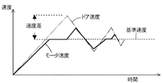
図22は、車両が前上り状態において、モータ速度を用いたフィードバック制御によりスライド扉を開扉させるときの、モータ速度とスライド扉のドア速度を測定した結果を示したものである。最初に、モータを基準速度に向けて加速させると、ドア速度も加速するが、このときドア速度がモータ速度を上回っている。これは、車両が前上り状態であるためスライド扉に加速方向の外力が作用して、スライド扉が連結ガタにより、先行加速していることを意味する。
モータ速度が基準速度に達すると、モータ速度は基準速度に合わせて一定に保たれるが、スライド扉は、依然として連結ガタに相当する分だけ継続加速し、その後、連結ガタが吸収されることでモータによるブレーキ効果により減速に転じる。同時に、連結ガタが吸収されたことでモータ速度はスライド扉に引っ張られる形で増速する。このモータ速度の増速が検出されると、フィードバック制御によりモータ速度は減速させられるが、そこでも、連結ガタによる速度差が生じて、モータ速度の加減速が繰り返され、その結果、ドア速度は大きな山と谷の繰り返しとなって現れる。
このような、ドア速度の大きな山と谷の繰り返しは、モータ速度を基準速度に向けて加速させたときに時に起こるドア速度とモータ速度との速度差が大きくなる程、多くなり、また、継続される。換言すれば、車両前下り状態における開扉時のように、スライド扉に減速方向の外力が作用する状況下では、連結ガタによるドア速度の先行加速は起こらないため、ドア速度の変動は無視できる程度に収まり、スライド扉を円滑に安定した速度で移動させることができるのである。
特開2003−97146
FIG. 22 shows the results of measuring the motor speed and the door speed of the sliding door when the sliding door is opened by feedback control using the motor speed when the vehicle is in the forward ascending state. First, when the motor is accelerated toward the reference speed, the door speed also increases, but at this time, the door speed exceeds the motor speed. This means that since the vehicle is in the front-up state, an external force in the acceleration direction acts on the slide door, and the slide door is accelerated ahead by the connecting backlash.
When the motor speed reaches the reference speed, the motor speed is kept constant according to the reference speed, but the sliding door is still continuously accelerated by the amount corresponding to the connected play, and then the connected play is absorbed. It turns to deceleration by the brake effect by the motor. At the same time, the motor speed increases by being pulled by the sliding door due to the absorption of the connecting play. When this increase in motor speed is detected, the motor speed is decelerated by feedback control, but there is also a speed difference due to connected play, and the acceleration / deceleration of the motor speed is repeated. As a result, the door speed is It appears as a repetition of large mountains and valleys.
Such repeated peaks and valleys with a large door speed increase as the speed difference between the door speed and the motor speed that occurs when the motor speed is accelerated toward the reference speed increases and continues. Is done. In other words, in the situation where an external force in the deceleration direction acts on the sliding door, such as when the door is opened in the forward-downward state of the vehicle, the door speed is not accelerated by the connecting backlash, so the fluctuation in the door speed can be ignored. The sliding door can be moved smoothly and at a stable speed.
JP2003-97146

モータ速度やドラム速度と、スライド扉の実際のドア速度との速度差は、モータ速度やドラム速度の両方を用いて演算することである程度予測でき、これにより、スライド扉をより安定した速度で移動させることができるが、この場合、モータの出力軸(若しくはこれと連動する歯車等)の実際の回転を検出することで、モータ速度を求めることが望ましい。PWM制御やDUTY制御下におかれるモータでは、脈派による検出は精度が劣るからである。   The speed difference between the motor speed and drum speed and the actual door speed of the sliding door can be predicted to some extent by calculating using both the motor speed and the drum speed, thereby moving the sliding door at a more stable speed. In this case, it is desirable to obtain the motor speed by detecting the actual rotation of the output shaft of the motor (or a gear or the like linked to the motor). This is because, in a motor placed under PWM control or DUTY control, detection by pulse group is inaccurate.

よって本発明は、開扉用ケーブル21’及び閉扉用ケーブル21”に連結され回転すると前記ケーブル21’、21”の巻取り及び引き出しを行うことで車両スライド扉11をスライド移動させるワイヤードラム30と、前記ワイヤードラム30を回転させるモータ24と、前記モータ24と前記ワイヤードラム30との間に設けられたクラッチ機構31と、前記ワイヤードラム30と常時連動して回転するドラム回転体126と、前記ドラム回転体126の回転を検出するドラム速度センサー137と、前記モータ24と常時連動して回転するモータ回転体131と、前記モータ回転体131の回転を検出するモータ速度センサー138と、ハウジング29とを有するものにおいて、前記ハウジング29は、中央のハウジングボディ122と前記ハウジングボディ122の一方側に位置するカバープレート121と前記ハウジングボディ122の他方側に位置するベースプレート120とを有し、前記ワイヤードラム30と前記クラッチ機構31は前記ハウジングボディ122と前記ベースプレート120との間の第1スペース123に設け、前記ドラム回転体126と前記モータ回転体131とは、前記ハウジングボディ122と前記カバープレート121との間の第2スペース124に設け、前記ドラム回転体126の回転軸128と前記モータ回転体131の回転軸130とは、前記ワイヤードラム30の支持軸28に対して平行に配置し、前記ハウジング29の前記カバプレート121には、前記モータ24の回転制御を司る制御部136を備えた制御基板135を取付け、前記制御基板135には前記ドラム速度センサー137及び前記モータ速度センサー138を設け、前記ドラム速度センサー137及び前記モータ速度センサー138は、前記カバープレート121に形成した窓139、140内にそれぞれ臨ませた車両スライド扉の動力スライド装置としたものである。 Accordingly, the present invention provides a wire drum 30 that slides and moves the vehicle slide door 11 by winding and pulling out the cables 21 ′ and 21 ″ when connected to the opening cable 21 ′ and the closing cable 21 ″ and rotating. The motor 24 for rotating the wire drum 30; the clutch mechanism 31 provided between the motor 24 and the wire drum 30; the drum rotating body 126 that always rotates in conjunction with the wire drum 30; A drum speed sensor 137 that detects the rotation of the drum rotating body 126, a motor rotating body 131 that always rotates in conjunction with the motor 24, a motor speed sensor 138 that detects the rotation of the motor rotating body 131, and the housing 29 in those with, the housing 29 includes a central housing body 122 Serial and cover plate 121 positioned on one side of the housing body 122 and a base plate 120 located on the other side of the housing body 122, and the wire drum 30 the clutch mechanism 31 and the housing body 122 and the base plate 120 The drum rotating body 126 and the motor rotating body 131 are provided in a second space 124 between the housing body 122 and the cover plate 121, and the drum rotating body 126 a rotary shaft 128 and the rotation shaft 130 of the motor rotation body 131, the parallel arranged with respect to the support shaft 28 of the wire drum 30, the cover plate 121 of the housing 29, rotation control of the motor 24 A control board 135 having a control unit 136 for controlling The control board 135 is provided with the drum speed sensor 137 and the motor speed sensor 138. The drum speed sensor 137 and the motor speed sensor 138 face the windows 139 and 140 formed in the cover plate 121, respectively. This is a power slide device for a vehicle slide door.

本願の請求項1に掛かる発明では、ワイヤードラム30とクラッチ機構31とドラム回転体126とモータ回転体131とは、ハウジング29内に設けると共に、ドラム回転体126の回転軸128と前記モータ回転体131の回転軸130とは、前記ワイヤードラム30の支持軸28に対して平行に配置しているので、ドラム回転体126とモータ回転体131とを、合理的にハウジング内に設けることができる。また、ハウジング29の外側カバプレート121には、モータ24の回転制御を司る制御部136を備えた制御基板135を取付け、前記制御基板135には前記ドラム速度センサー137及び前記モータ速度センサー138を設けているため、センサー137、138の設置場所も合理的となる。また、ドラム速度センサー137及びモータ速度センサー138は、カバープレート121に形成した窓139、140内にそれぞれ臨ませているため、制御基板135をカバープレート121に取付ける際の収まりが良く、センサー137、138と回転素子132、133との距離も短縮できる。
また、請求項に掛かる発明では、前記ドラム回転体126は前記支持軸28を介して前記ワイヤードラム30と連動する構成とし、前記モータ回転体131は前記モータ24により回転するウオームホイール26を介して前記モータ24と連動する構成としているため、ドラム回転体126はワイヤードラム30の回転を正確に反映でき、モータ回転体131はモータ24の回転を正確に反映でき、測定精度の向上が期待できる。
また、請求項に掛かる発明では、前記ドラム回転体126と前記モータ回転体131とは、前記支持軸28の軸芯方向において互いに重合しないように配置できるので、ハウジング29の大型化を抑制できる。
In the invention according to claim 1 of the present application, the wire drum 30, the clutch mechanism 31, the drum rotating body 126, and the motor rotating body 131 are provided in the housing 29, and the rotating shaft 128 of the drum rotating body 126 and the motor rotating body are provided. Since the rotating shaft 130 of 131 is arranged in parallel to the support shaft 28 of the wire drum 30, the drum rotating body 126 and the motor rotating body 131 can be reasonably provided in the housing. Further, the outer cover plate 121 of the housing 29, fitted with a control board 135 having a control unit 136 which governs the rotation control of the motor 24, the said control board 135 to the drum speed sensor 137 and the motor speed sensor 138 Since it is provided, the installation location of the sensors 137 and 138 is also rational . Also, the drum speed sensor 137 and the motor speed sensor 138, since the to face each in the window 139 and 140 formed in the cover plate 121, good fit when mounting the control board 135 to the cover plate 121, a sensor 137, The distance between 138 and the rotating elements 132 and 133 can also be shortened.
In the invention according to claim 2 , the drum rotating body 126 is configured to be interlocked with the wire drum 30 via the support shaft 28, and the motor rotating body 131 is interposed via a worm wheel 26 rotated by the motor 24. Therefore, the drum rotating body 126 can accurately reflect the rotation of the wire drum 30, and the motor rotating body 131 can accurately reflect the rotation of the motor 24, so that improvement in measurement accuracy can be expected. .
In the invention according to claim 3 , since the drum rotating body 126 and the motor rotating body 131 can be arranged so as not to overlap each other in the axial direction of the support shaft 28, the enlargement of the housing 29 can be suppressed. .

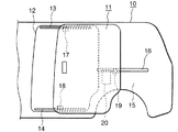
本発明の実施例を図により説明すると、10は車体、11は車体10にスライド自在に取付けられたスライド扉であり、車体10のドア開口12を塞ぐ閉扉位置と開扉位置との間をスライド移動する。   An embodiment of the present invention will be described with reference to the drawings. Reference numeral 10 denotes a vehicle body, and 11 a slide door slidably attached to the vehicle body 10, and slides between a closed position and an open position that close the door opening 12 of the vehicle body 10. Moving.

ドア開口12の上部近傍の車体10にはアッパーレール13が固定され、ドア開口12の下部近傍の車体10にはロワーレール14が固定され、車体10の後部側面であるクオータパネル15にはセンターレール16が固定される。スライド扉11には、アッパーレール13にスライド自在に係合するアッパーブラケット17と、ロワーレール14にスライド自在に係合するロワーブラケット18と、センターレール16にスライド自在に係合するセンターブラケット19とが設けられる。各ブラケット17、18、19は、好適にはスライド扉11に揺動自在に軸止され、これらのブラケットとレールとの係合によりスライド扉11は車体10に開扉方向及び閉扉方向にスライド自在に取付けられる。   An upper rail 13 is fixed to the vehicle body 10 near the upper portion of the door opening 12, a lower rail 14 is fixed to the vehicle body 10 near the lower portion of the door opening 12, and a center rail 16 is attached to the quarter panel 15 on the rear side surface of the vehicle body 10. Is fixed. The slide door 11 includes an upper bracket 17 slidably engaged with the upper rail 13, a lower bracket 18 slidably engaged with the lower rail 14, and a center bracket 19 slidably engaged with the center rail 16. Provided. Each bracket 17, 18, 19 is preferably pivotally fixed to the slide door 11, and the slide door 11 is slidable in the door opening direction and the door closing direction with respect to the vehicle body 10 by the engagement between the bracket and the rail. Mounted on.

本発明による動力スライド装置の動力ユニット20は、図1〜図3のように、前記スライド扉11の内部空間50(図2)に配置される場合と、クオータパネル15の室内側空間に配置される場合とがあるが、本発明の要旨とは無関係である。   The power unit 20 of the power slide device according to the present invention is arranged in the interior space 50 (FIG. 2) of the slide door 11 and in the indoor space of the quarter panel 15 as shown in FIGS. However, it is not related to the gist of the present invention.

前記動力ユニット20には、図5〜7のように、ワイヤーケーブルの牽引及び引き出しを司るワイヤードラム30が設けられ、ワイヤードラム30には2本のワイヤーケーブル、即ち、開扉用ケーブル21’と閉扉用ケーブル21”の基端側がそれぞれ連結される。ワイヤードラム30が開扉方向に回転すると、開扉用ケーブル21’は巻き取られ閉扉用ケーブル21”は引き出され、ワイヤードラム30が閉扉方向に回転すると、開扉用ケーブル21’は引き出され閉扉用ケーブル21”は巻き取られる関係になっている。   As shown in FIGS. 5 to 7, the power unit 20 is provided with a wire drum 30 for pulling and pulling the wire cable. The wire drum 30 includes two wire cables, that is, a door opening cable 21 ′. The proximal end side of the closing cable 21 "is connected. When the wire drum 30 rotates in the opening direction, the opening cable 21 'is wound up and the closing cable 21" is pulled out, and the wire drum 30 is closed. , The door opening cable 21 'is drawn out, and the door closing cable 21 "is wound up.

前記開扉用ケーブル21’は、図2、3のように、スライド扉11の前側下部位置、即ち、前記ロワーブラケット18の近傍位置から、スライド扉11の外部に車体側(ロワーブラケット18側)に向けて引き出される。スライド扉11から引き出された開扉用ケーブル21’は、ロワーブラケット18のプーリー(図示なし)を経由した後、ロワーレール14内を後方に伸びてロワーレール14の後端部若しくはその近傍の車体10に固定される。これにより、閉扉状態で開扉用ケーブル21’が巻き取られると、ロワーブラケット18を介してスライド扉11は後方に(開扉方向に)スライドする。   As shown in FIGS. 2 and 3, the door opening cable 21 ′ is located on the vehicle body side (lower bracket 18 side) outside the slide door 11 from the lower position on the front side of the slide door 11, that is, in the vicinity of the lower bracket 18. It is pulled out toward. The opening cable 21 ′ pulled out from the slide door 11 passes through the pulley (not shown) of the lower bracket 18 and then extends rearward in the lower rail 14 to the rear end of the lower rail 14 or the vehicle body 10 in the vicinity thereof. Fixed. Accordingly, when the opening cable 21 ′ is wound in the closed state, the sliding door 11 slides backward (in the opening direction) via the lower bracket 18.

前記閉扉用ケーブル21”は、スライド扉11の後側の上下の中央部、即ち、前記センターブラケット19の近傍位置から、スライド扉11の外部に車体側(センターブラケット19側)に向けて引き出される。スライド扉11から引き出された閉扉用ケーブル21”は、センターブラケット19のプーリー(図示なし)を経由した後、センターレール16の前端部若しくはその近傍の車体10に固定される。これにより、開扉状態で閉扉用ケーブル21”が巻き取られると、センターブラケット19を介してスライド扉11は前方に(閉扉方向に)スライドする。   The closing cable 21 ″ is drawn from the upper and lower central portions on the rear side of the slide door 11, that is, from the position in the vicinity of the center bracket 19 to the outside of the slide door 11 toward the vehicle body side (center bracket 19 side). The closing cable 21 ″ drawn out from the slide door 11 passes through a pulley (not shown) of the center bracket 19 and is then fixed to the vehicle body 10 at or near the front end of the center rail 16. Thus, when the door closing cable 21 ″ is wound in the open state, the slide door 11 slides forward (in the door closing direction) via the center bracket 19.

なお、動力ユニット20をクオータパネル15の室内側空間に配置する場合には、図4のように、開扉用ケーブル21’の他端側は前記センターレール16の前部に軸止された前側プーリー22を経由してスライド扉11のセンターブラケット19に連結し、同様に、閉扉用ケーブル21”の他端側はセンターレール16の後部に軸止された後側プーリー23を経由してセンターブラケット19に連結する。   When the power unit 20 is arranged in the indoor space of the quarter panel 15, the other end side of the door opening cable 21 ′ is a front side that is axially fixed to the front portion of the center rail 16 as shown in FIG. 4. It connects with the center bracket 19 of the slide door 11 via the pulley 22, Similarly, the other end side of the cable 21 "for closing doors is center bracket via the rear pulley 23 pivotally fixed to the rear part of the center rail 16. 19 is connected.

図8はワイヤーケーブル21’、21”のテンションを適正圧に維持するテンション機構100を示しており、好適には、動力ユニット20に設けられる。テンション機構100のケース101内にはケーブル21’、21”が当接する一対のテンションローラ102、103が設けられる。テンションローラ102、103は、テンション軸104、105で軸止され、テンションバネ106の弾力で互いに接近するように付勢される。 8 shows a tension mechanism 100 that maintains the tension of the wire cables 21 ′ and 21 ″ at an appropriate pressure, and is preferably provided in the power unit 20. In the case 101 of the tension mechanism 100, the cables 21 ′, A pair of tension rollers 102 and 103 against which 21 ″ abuts are provided. The tension rollers 102 and 103 are supported by tension shafts 104 and 105 and are urged so as to approach each other by the elasticity of the tension spring 106.

図5、6において、動力ユニット20のモータ24の出力軸には円筒ウオーム25が取付けられており、円筒ウオーム25にはウオームホイール26を噛合させる。ウオームホイール26は、支持軸28により動力ユニット20のハウジング29内に軸止され、支持軸28には前記ワイヤードラム30も軸止されている。ウオームホイール26とワイヤードラム30との間には、クラッチ機構31が設けられ、クラッチ機構31がオンになるとウオームホイール26の回転がワイヤードラム30に伝達され、オフになるとワイヤードラム30はウオームホイール26に対して自由となる。このため、図5において、モータ24の正転によりウオームホイール26が時計回転している最中にクラッチ機構31がオンになると、ワイヤードラム30も時計回転して開扉用ケーブル21’は引き出され閉扉用ケーブル21”は巻き取られ、反対にモータ24の逆転によりウオームホイール26が反時計回転している最中にクラッチ機構31がオンになると、ワイヤードラム30も反時計方向に回転して開扉用ケーブル21’は巻き取られ閉扉用ケーブル21”は引き出されることになる。   5 and 6, a cylindrical worm 25 is attached to the output shaft of the motor 24 of the power unit 20, and a worm wheel 26 is engaged with the cylindrical worm 25. The worm wheel 26 is fixed in the housing 29 of the power unit 20 by a support shaft 28, and the wire drum 30 is also fixed to the support shaft 28. A clutch mechanism 31 is provided between the worm wheel 26 and the wire drum 30. When the clutch mechanism 31 is turned on, the rotation of the worm wheel 26 is transmitted to the wire drum 30, and when the clutch mechanism 31 is turned off, the wire drum 30 is moved to the worm wheel 26. Will be free. Therefore, in FIG. 5, when the clutch mechanism 31 is turned on while the worm wheel 26 is rotated clockwise by the normal rotation of the motor 24, the wire drum 30 is also rotated clockwise and the opening cable 21 'is pulled out. If the clutch mechanism 31 is turned on while the worm wheel 26 is rotating counterclockwise by the reverse rotation of the motor 24, the wire drum 30 is also rotated counterclockwise and opened. The door cable 21 'is wound up and the door closing cable 21 "is pulled out.

前記クラッチ機構31は、本願発明の要旨とは直接関係しておらず、どのようなクラッチ機構を用いても自由であるが、本願発明では、特願2003−400812において詳細に説明したクラッチ機構を採用している。クラッチ機構31は電気制御でオンオフする電磁コイル部60を備えたクラッチであり、概略的には、電磁コイル部60がオンになるとクラッチ機構31は連結状態となり、オフになると切断状態となるが、後述するように電磁コイル部60がオフの時でもクラッチ連結状態(ブレーキクラッチ連結状態)を維持できる特徴を備えている。電磁コイル部60は前記支持軸28周りに配置した円筒状であり、電磁コイル部60はハウジング29に対して固定され、支持軸28は電磁コイル部60に対して回転自在となっている。ウオームホイール26は電磁コイル部60の外周に回転自在に支持される。図6において、電磁コイル部60の左方には環状アーマチュア61が近接配置され、アーマチュア61は支持軸28に回転自在に軸止され、且つその軸方向に移動自在となっている。アーマチュア61はブレーキ解除バネ62の弱い弾力で電磁コイル部60から離れるように左方に付勢され、支持軸28の段部に当接している。アーマチュア61の右面は、電磁コイル部60がオンになるとブレーキ解除バネ62の弾力に抗して電磁コイル部60の磁力で引き寄せられて電磁コイル部60の左面に密着する。この密着により生じる摩擦抵抗がクラッチ連結に必要なブレーキ抵抗となる。   The clutch mechanism 31 is not directly related to the gist of the present invention, and any clutch mechanism can be used. However, in the present invention, the clutch mechanism described in detail in Japanese Patent Application No. 2003-400122 is used. Adopted. The clutch mechanism 31 is a clutch provided with an electromagnetic coil unit 60 that is turned on / off by electric control. Generally, the clutch mechanism 31 is in a connected state when the electromagnetic coil unit 60 is turned on, and is in a disconnected state when turned off. As will be described later, the clutch coupling state (brake clutch coupling state) can be maintained even when the electromagnetic coil unit 60 is off. The electromagnetic coil part 60 is a cylindrical shape arranged around the support shaft 28, the electromagnetic coil part 60 is fixed to the housing 29, and the support shaft 28 is rotatable with respect to the electromagnetic coil part 60. The worm wheel 26 is rotatably supported on the outer periphery of the electromagnetic coil unit 60. In FIG. 6, an annular armature 61 is disposed close to the left side of the electromagnetic coil section 60, and the armature 61 is rotatably supported by the support shaft 28 and is movable in the axial direction thereof. The armature 61 is urged to the left so as to be separated from the electromagnetic coil portion 60 by the weak elasticity of the brake release spring 62 and is in contact with the step portion of the support shaft 28. When the electromagnetic coil unit 60 is turned on, the right surface of the armature 61 is attracted by the magnetic force of the electromagnetic coil unit 60 against the elasticity of the brake release spring 62 and closely contacts the left surface of the electromagnetic coil unit 60. The frictional resistance generated by this close contact becomes a brake resistance necessary for clutch engagement.

前記アーマチュア61の左面にはカム体63(図9)を固定する。アーマチュア61とカム体63とは一体的に動くもので、一体形成しても良い。カム体63のカム面64は、図9のように、支持軸28の軸芯方向の左方に膨らむ頂部64Aと、切欠により形成した底部64Bと、これらを繋げる斜面64Cを備えた規則性のある環状凹凸面である。斜面64Cは、中腹にクラッチ保持面64Dを備えた2段斜面で、中腹のクラッチ保持面64Dは、電磁コイル部60がオフの時にクラッチ機構31をブレーキクラッチ連結状態に維持する機能を備える。図11はカム面64の詳細な形状を示し、斜面64Cは支持軸28の軸芯Xと直交する面に対して好適には約30度(軸芯Xに対して好適には約60度)の斜面であり、また、クラッチ保持面64Dは軸芯Xに対して直交する平坦面でも良いが、好適には該平坦面に対して約10度の後退面に形成される。 A cam body 63 (FIG. 9) is fixed to the left surface of the armature 61. The armature 61 and the cam body 63 move integrally, and may be integrally formed. As shown in FIG. 9, the cam surface 64 of the cam body 63 has regularity provided with a top portion 64 </ b> A that swells to the left in the axial direction of the support shaft 28, a bottom portion 64 </ b> B formed by a notch, and an inclined surface 64 </ b> C that connects them. It is a certain annular uneven surface. The slope 64C is a two-stage slope having a clutch holding surface 64D on the middle, and the middle clutch holding surface 64D has a function of maintaining the clutch mechanism 31 in the brake clutch connected state when the electromagnetic coil unit 60 is off. Figure 11 shows a detailed shape of the cam surface 64, the inclined surface 64C is for the plane perpendicular to the axis X preferably about 30 degrees of the support shaft 28 (preferably about 60 degrees relative to the axial center X) The clutch holding surface 64D may be a flat surface orthogonal to the axis X, but is preferably formed on a receding surface of about 10 degrees with respect to the flat surface .

図6において、前記カム体63の左方には移動歯車体65(図10)が設けられる。移動歯車体65は支持軸28に回転自在で且つその軸方向に移動自在に軸止されており、その外周部には右方のウオームホイール26に向かって伸びる複数の脚部66が形成されている。脚部66の右方先端部は、図6、12のように、前記ウオームホイール26の係合溝67に係合させ、ウオームホイール26の回転で移動歯車体65も連動して回転するようになっている。脚部66は係合溝67に対して支持軸28の軸方向においてスライド自在であるが、移動歯車体65が最大に左方に移動しても脚部66と係合溝67との係合は外れず、従って、移動歯車体65とウオームホイール26とは常時一体的に回転する。また、脚部66と係合溝67との間には、図13のように、回転方向における隙間Yが形成され、脚部66(移動歯車体65)は係合溝67(ウオームホイール26)に対して約6度程度だけ自由に回転できる設定にする。移動歯車体65の左面には、支持軸28を中心とする移動環状ギア部68が設けられる。   In FIG. 6, a moving gear body 65 (FIG. 10) is provided on the left side of the cam body 63. The moving gear body 65 is rotatably supported by the support shaft 28 and is axially fixed so as to be movable in its axial direction, and a plurality of leg portions 66 extending toward the right worm wheel 26 are formed on the outer periphery thereof. Yes. As shown in FIGS. 6 and 12, the right end of the leg 66 is engaged with the engagement groove 67 of the worm wheel 26 so that the moving gear body 65 rotates in conjunction with the rotation of the worm wheel 26. It has become. The leg 66 is slidable in the axial direction of the support shaft 28 with respect to the engagement groove 67, but the engagement between the leg 66 and the engagement groove 67 is possible even when the movable gear body 65 moves to the left at the maximum. Therefore, the moving gear body 65 and the worm wheel 26 always rotate integrally. Further, as shown in FIG. 13, a gap Y in the rotational direction is formed between the leg portion 66 and the engagement groove 67, and the leg portion 66 (moving gear body 65) is engaged with the engagement groove 67 (worm wheel 26). Is set so that it can rotate freely by about 6 degrees. On the left surface of the moving gear body 65, a moving annular gear portion 68 centering on the support shaft 28 is provided.

前記移動歯車体65の左方には、固定歯車体69が配置され、移動歯車体65と固定歯車体69との間には移動歯車体65を右方に押圧するクラッチ解除バネ70が設けられる。固定歯車体69の左面は前記ワイヤードラム30に固定され、両者は一体的に回転する。ワイヤードラム30は支持軸28と一体回転するように支持軸28の左端に固定される。固定歯車体69の右面には固定環状ギア部71が設けられ、移動歯車体65がクラッチ解除バネ70の弾力に抗して支持軸28に対して左方にスライドすると、移動環状ギア部68は固定環状ギア部71に噛合する。ギア部68とギア部71とが噛合した状態が、クラッチ機構31の通常クラッチ連結状態となり、ウオームホイール26の回転はワイヤードラム30に伝達される。反対に、移動歯車体65がクラッチ解除バネ70の弾力で支持軸28に対して右方にスライドすると、移動環状ギア部68は固定環状ギア部71から離脱してクラッチ切断状態となり、ウオームホイール26の回転はワイヤードラム30に伝達されなくなる。   A fixed gear body 69 is disposed on the left side of the moving gear body 65, and a clutch release spring 70 that presses the moving gear body 65 to the right is provided between the moving gear body 65 and the fixed gear body 69. . The left surface of the fixed gear body 69 is fixed to the wire drum 30, and both rotate integrally. The wire drum 30 is fixed to the left end of the support shaft 28 so as to rotate integrally with the support shaft 28. A fixed annular gear portion 71 is provided on the right surface of the fixed gear body 69. When the movable gear body 65 slides to the left with respect to the support shaft 28 against the elasticity of the clutch release spring 70, the movable annular gear portion 68 is It meshes with the fixed annular gear portion 71. The state in which the gear portion 68 and the gear portion 71 mesh with each other is the normal clutch engagement state of the clutch mechanism 31, and the rotation of the worm wheel 26 is transmitted to the wire drum 30. On the other hand, when the moving gear body 65 slides to the right with respect to the support shaft 28 by the elasticity of the clutch release spring 70, the moving annular gear portion 68 is disengaged from the fixed annular gear portion 71 and the clutch is disengaged. Is not transmitted to the wire drum 30.

前記移動歯車体65には、図10のように、前記カム体63のカム面64と協同して移動歯車体65を前記クラッチ解除バネ70の弾力に抗して左方にスライドさせるカム面72が形成される。カム面72は、支持軸28の軸芯方向において右方に膨らむ頂部72Aと、底部72Bと、これらを繋げる斜面72Cを備えた規則性のある環状凹凸面である。カム面72はカム面64に対して略対称の構造を備えているが、本実施例では、クラッチ保持面は備えていない。しかし、クラッチ保持面はカム面64とカム面72のいずれか一方側に形成すれば所期の効果を奏するものである。   As shown in FIG. 10, the moving gear body 65 is slid leftward against the elastic force of the clutch release spring 70 in cooperation with the cam surface 64 of the cam body 63. Is formed. The cam surface 72 is a regular annular concavo-convex surface having a top portion 72A that swells to the right in the axial direction of the support shaft 28, a bottom portion 72B, and a slope 72C that connects them. The cam surface 72 has a substantially symmetrical structure with respect to the cam surface 64, but in this embodiment, no clutch holding surface is provided. However, if the clutch holding surface is formed on either the cam surface 64 or the cam surface 72, the desired effect can be obtained.

前記移動歯車体65がクラッチ解除バネ70の弾力で右方にスライドすると、通常は図14、15のように、カム面72の頂部72Aがカム面64の底部64Bにぴったり合致し、移動環状ギア部68は固定環状ギア部71から離脱してクラッチ切断状態となる。このクラッチ切断状態において、電磁コイル部60をオンにするとアーマチュア61の右面はブレーキ解除バネ62の弾力に抗して電磁コイル部60の左面(摩擦面)に磁力で引き寄せられて密着し、アーマチュア61及びカム体63にはブレーキ抵抗が付与される。ついで、モータ24の動力で移動歯車体65(カム面72)を回転させると、ブレーキ抵抗によりカム体63は回転が規制された状態にあるから、図16のようにカム面同士による楔効果でカム面72とカム体63のカム面64とは位相がずれて、移動歯車体65はクラッチ解除バネ70の弾力に抗して左方に押し出され、図17のように、移動環状ギア部68は固定環状ギア部71に噛合し通常クラッチ連結状態になる。   When the moving gear body 65 is slid rightward by the elasticity of the clutch release spring 70, the top portion 72A of the cam surface 72 is normally aligned with the bottom portion 64B of the cam surface 64 as shown in FIGS. The part 68 is detached from the fixed annular gear part 71 and is in a clutch disengaged state. In this clutch disengaged state, when the electromagnetic coil unit 60 is turned on, the right surface of the armature 61 resists the elasticity of the brake release spring 62 and is attracted to the left surface (friction surface) of the electromagnetic coil unit 60 by a magnetic force. In addition, a brake resistance is applied to the cam body 63. Next, when the moving gear body 65 (cam surface 72) is rotated by the power of the motor 24, the cam body 63 is in a state in which the rotation is restricted by the brake resistance. The cam surface 72 and the cam surface 64 of the cam body 63 are out of phase, and the moving gear body 65 is pushed to the left against the elasticity of the clutch release spring 70, and as shown in FIG. Meshes with the fixed annular gear portion 71 and is normally engaged with the clutch.

図16、17の通常クラッチ連結状態でモータ24及び電磁コイル部60を共にオフにすると、アーマチュア61及びカム体63はブレーキ抵抗から解放される。すると、クラッチ解除バネ70の弾力により移動歯車体65は、カム体63を逃げ方向(図16において下方)に回転させながら右方へ移動し、移動歯車体65は、固定歯車体69との噛合状態が外れる前に、図18、19のように、移動歯車体65の頂部72Aがカム体63のクラッチ保持面64Dに当接し、これにより、移動歯車体65はカム体63を回転させることができなくなると共に右方への移動も規制される。このため、電磁コイル部60がオフの状態であっても、移動歯車体65と固定歯車体69との噛合が維持されクラッチ機構31はブレーキクラッチ連結状態となる。   16 and 17, when both the motor 24 and the electromagnetic coil unit 60 are turned off, the armature 61 and the cam body 63 are released from the brake resistance. Then, the moving gear body 65 moves to the right while rotating the cam body 63 in the escape direction (downward in FIG. 16) due to the elasticity of the clutch release spring 70, and the moving gear body 65 meshes with the fixed gear body 69. Before the state is removed, as shown in FIGS. 18 and 19, the top portion 72 </ b> A of the moving gear body 65 abuts on the clutch holding surface 64 </ b> D of the cam body 63, whereby the moving gear body 65 can rotate the cam body 63. It will not be possible, and movement to the right will be restricted. For this reason, even if the electromagnetic coil part 60 is an OFF state, the meshing of the moving gear body 65 and the fixed gear body 69 is maintained, and the clutch mechanism 31 is in the brake clutch connected state.

図18、19のブレーキクラッチ連結状態では、頂部72Aとクラッチ保持面64Dとの当接による抵抗で、移動歯車体65とアーマチュア61及びカム体63とは、一体的に回転する状態に維持される。従って、移動歯車体65を図19において上方に移動させるために固定歯車体69を上方に回転させても、アーマチュア61及びカム体63も連動して上動することになるから、ブレーキクラッチ連結状態は解除されない。なお、移動歯車体65とカム体63との一体状態に保つために必要な頂部72Aとクラッチ保持面64Dとの間の摩擦力は、クラッチ保持面64Dが支持軸28の軸芯Xに対して直交する平坦面であっても確保できるが、クラッチ保持面64Dを約10度程度の後退面にすると良好な摩擦が得られる。   18 and 19, the moving gear body 65, the armature 61, and the cam body 63 are maintained in a state of rotating integrally by the resistance caused by the contact between the top portion 72A and the clutch holding surface 64D. . Accordingly, even if the fixed gear body 69 is rotated upward in order to move the moving gear body 65 upward in FIG. 19, the armature 61 and the cam body 63 also move up in conjunction with each other. Is not released. Note that the frictional force between the top 72A and the clutch holding surface 64D required to keep the moving gear body 65 and the cam body 63 in one piece is that the clutch holding surface 64D is against the axis X of the support shaft 28. Even if it is an orthogonal flat surface, it can be ensured, but if the clutch holding surface 64D is a retreating surface of about 10 degrees, good friction can be obtained.

前記頂部72Aと前記クラッチ保持面64Dとの当接は、後述する「ブレーキクラッチ連結状態の手動解除操作」のように、電磁コイル部60をオンにしてから移動歯車体65をアーマチュア61及びカム体63に対して相対的に図18、19において上方に移動させると解除できる。このときに必要な移動歯車体65の回転角度は約5度であり、脚部66と係合溝67との間に形成された前記隙間Yにより得られる移動歯車体65の自由な回転角度(約6度)より小さく設定される。   The abutment between the top portion 72A and the clutch holding surface 64D is achieved by turning on the electromagnetic coil portion 60 after the electromagnetic coil portion 60 is turned on, as will be described later. It can be canceled by moving upward in FIGS. The rotation angle of the moving gear body 65 required at this time is about 5 degrees, and the free rotation angle of the moving gear body 65 obtained by the gap Y formed between the leg 66 and the engagement groove 67 ( Is set smaller than about 6 degrees).

前記ハウジング29は、金属製ベースプレート120と、金属製又は樹脂製カバープレート121と、プレート120とプレート121の間の樹脂製ハウジングボディ122とから構成され、ベースプレート120とボディ122との間には第1スペース123が、また、カバープレート121とボディ122との間には第2スペース124が形成される。第1スペース123には、前記ワイヤードラム30及びクラッチ機構31が収納される。   The housing 29 includes a metal base plate 120, a metal or resin cover plate 121, and a resin housing body 122 between the plate 120 and the plate 121. A first space 123 is formed, and a second space 124 is formed between the cover plate 121 and the body 122. In the first space 123, the wire drum 30 and the clutch mechanism 31 are accommodated.

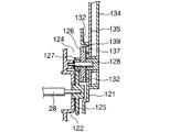
図6、7のように、前記支持軸28の一方の端部はハウジングボディ122を貫通して第2スペース124内に突出させ、その突出端には大径歯車125を固定する。大径歯車125にはドラム回転体126の小径歯車127を噛合させる。ドラム回転体126は支持軸28と平行の軸128で第2スペース124内に軸止され、前記ワイヤードラム30の回転で支持軸28が回転すると、これに連動して回転する。   As shown in FIGS. 6 and 7, one end of the support shaft 28 penetrates the housing body 122 and protrudes into the second space 124, and a large-diameter gear 125 is fixed to the protruding end. The small-diameter gear 127 of the drum rotating body 126 is meshed with the large-diameter gear 125. The drum rotating body 126 is fixed in the second space 124 by a shaft 128 parallel to the support shaft 28. When the support shaft 28 is rotated by the rotation of the wire drum 30, the drum rotating body 126 rotates in conjunction therewith.

図6のように、前記ウオームホイール26には、平行歯車129を噛合させる。平行歯車129は、第1スペース123内でウオームホイール26と同一平面上に配置される。平行歯車129の軸130は支持軸28と平行であり、一方の端部はハウジングボディ122を貫通して第2スペース124内に突出させ、その突出端にはモータ回転体131を固定する。モータ回転体131は、ウオームホイール26を介してモータ24と連動して回転する。モータ回転体131は、前記支持軸28の軸芯方向において前記ドラム回転体126と重合しないように配置する。   As shown in FIG. 6, a parallel gear 129 is meshed with the worm wheel 26. The parallel gear 129 is disposed on the same plane as the worm wheel 26 in the first space 123. The shaft 130 of the parallel gear 129 is parallel to the support shaft 28, and one end of the parallel gear 129 passes through the housing body 122 and protrudes into the second space 124, and the motor rotating body 131 is fixed to the protruding end. The motor rotating body 131 rotates in conjunction with the motor 24 via the worm wheel 26. The motor rotator 131 is disposed so as not to overlap the drum rotator 126 in the axial direction of the support shaft 28.

前記ドラム回転体126とモータ回転体131とには、それぞれ、磁気体等からなるドラム回転素子132とモータ回転素子133とが設けられる。   The drum rotating body 126 and the motor rotating body 131 are respectively provided with a drum rotating element 132 and a motor rotating element 133 made of a magnetic body or the like.

前記カバープレート121の外側には、制御ユニット134が取付けられる。制御ユニット134の制御基板135には、制御部136が設けられると共に、ドラム回転素子132と共同してワイヤードラム30の回転速度を検出するドラム速度センサー137と、モータ回転素子133と共同してモータ24の回転速度を検出するモータ速度センサー138とが設けられる。センサー137、138は好適にはホールICであり、前記カバープレート121に形成した窓139、140を介して回転素子132、133を検出できるようにする。また、制御基板135に対して突出するセンサー137、138自体を窓139、140内に配置すると、制御基板135の収まりが良く、センサー137、138と回転素子132、133との距離も短縮できる。 A control unit 134 is attached to the outside of the cover plate 121. The control board 135 of the control unit 134 is provided with a control unit 136, a drum speed sensor 137 that detects the rotation speed of the wire drum 30 in cooperation with the drum rotation element 132, and a motor in cooperation with the motor rotation element 133. A motor speed sensor 138 for detecting 24 rotational speeds is provided. The sensors 137 and 138 are preferably Hall ICs so that the rotating elements 132 and 133 can be detected through windows 139 and 140 formed in the cover plate 121 . Further, if the sensors 137 and 138 themselves that protrude with respect to the control board 135 are arranged in the windows 139 and 140, the control board 135 can be easily accommodated, and the distance between the sensors 137 and 138 and the rotating elements 132 and 133 can be shortened.

(クラッチの作用)
クラッチ機構31の作用を説明する。電磁コイル部60がオフの状態では、アーマチュア61と電磁コイル部60との間には実質的な摩擦抵抗は発生しない。この状態で、モータ24の正転により、円筒ウオーム25を回転させると、ウオームホイール26は図5において時計回転し、移動歯車体65も脚部66と係合溝67との係合により時計回転する。このとき、移動歯車体65はクラッチ解除バネ70の弾力で右方に移動していて、図6、15のように、移動歯車体65の移動ギア部68は固定歯車体69の固定ギア部71から離脱しており(クラッチ切断状態)、また、移動歯車体65のカム面72は、図14のように、カム体63のカム面64と互いに近接する状態で接面している。従って、この状態でモータ24を正転させると、移動歯車体65と、カム体63と、カム体63と一体のアーマチュア61とが共に回転するだけで、移動歯車体65は固定歯車体69に向けて移動しない。
(Action of clutch)
The operation of the clutch mechanism 31 will be described. In a state where the electromagnetic coil unit 60 is off, no substantial frictional resistance is generated between the armature 61 and the electromagnetic coil unit 60. In this state, when the cylindrical worm 25 is rotated by the normal rotation of the motor 24, the worm wheel 26 rotates clockwise in FIG. 5, and the moving gear body 65 also rotates clockwise by the engagement between the leg 66 and the engagement groove 67. To do. At this time, the moving gear body 65 is moved rightward by the elasticity of the clutch release spring 70, and the moving gear portion 68 of the moving gear body 65 is fixed to the fixed gear portion 71 of the fixed gear body 69 as shown in FIGS. 14 and the cam surface 72 of the moving gear body 65 is in contact with the cam surface 64 of the cam body 63 so as to be close to each other as shown in FIG. Therefore, when the motor 24 is rotated forward in this state, the moving gear body 65, the cam body 63, and the armature 61 integrated with the cam body 63 rotate together, and the moving gear body 65 becomes the fixed gear body 69. Do not move towards.

上記状態(図14、15)で、電磁コイル部60をオンにすると、アーマチュア61はブレーキ解除バネ62の弾力に抗して発生磁力により電磁コイル部60に引き寄せられて電磁コイル部60とアーマチュア61との間に所定のブレーキ抵抗が発生し、これにより、アーマチュア61及びカム体63の共回り回転が規制され、移動歯車体65はカム体63に対して支持軸28を中心に相対的に回転する。すると、カム面72とカム面64とは図16のように位相がずれて、移動歯車体65はクラッチ解除バネ70の弾力に抗して固定歯車体69に向かって押し出され、図17のように、移動歯車体65の移動環状ギア部68は固定歯車体69の固定ギア部71に係合して通常クラッチ連結状態となる。これにより、モータ24の回転は固定歯車体69を介してワイヤードラム30に伝達され、閉扉用ケーブル21”が巻き取られてスライド扉11は閉扉方向に移動する。なお、クラッチが連結された後は、アーマチュア61及びカム体63も移動歯車体65と共に回転する。   When the electromagnetic coil unit 60 is turned on in the above state (FIGS. 14 and 15), the armature 61 is attracted to the electromagnetic coil unit 60 by the generated magnetic force against the elasticity of the brake release spring 62, and the electromagnetic coil unit 60 and the armature 61. A predetermined brake resistance is generated between the armature 61 and the cam body 63, thereby restricting the rotation of the armature 61 and the cam body 63. The moving gear body 65 rotates relative to the cam body 63 about the support shaft 28. To do. Then, the cam surface 72 and the cam surface 64 are out of phase as shown in FIG. 16, and the moving gear body 65 is pushed out toward the fixed gear body 69 against the elasticity of the clutch release spring 70, as shown in FIG. In addition, the moving annular gear portion 68 of the moving gear body 65 is engaged with the fixed gear portion 71 of the fixed gear body 69 to be in the normal clutch engaged state. As a result, the rotation of the motor 24 is transmitted to the wire drum 30 via the fixed gear body 69, the door closing cable 21 "is wound up, and the slide door 11 moves in the door closing direction. The armature 61 and the cam body 63 also rotate with the moving gear body 65.

スライド扉11が閉扉方向に移動している最中に、モータ24及び電磁コイル部60をオフにすると、ウオームホイール26に係合している移動歯車体65は回転停止し、アーマチュア61及びカム体63はブレーキ抵抗から解放され、クラッチ解除バネ70の弾力により移動歯車体65は、カム体63を逃げ方向(図16、17において下方)に回転させながら右方へ戻される。すると、移動歯車体65は、固定歯車体69との噛合状態が外れる前に、図18、19のように、移動歯車体65の頂部72Aがカム体63のクラッチ保持面64Dに当接し、これにより、移動歯車体65はカム体63を回転させることができなくなると共に右方への移動も規制された状態になる。このため、電磁コイル部60がオフの状態であっても、移動歯車体65が固定歯車体69と噛合するブレーキクラッチ連結状態が維持される。このようなブレーキクラッチ連結状態では、スライド扉11はモータ24側の減速機構に直結されるため、実質的に不動状態に保たれる。従って、利用者が意図的にモータ24及び電磁コイル部60をオフにすれば、スライド扉11を所望の中間開扉位置に保持させることができる。また、この途中停止を制御部136による自動制御で行うようにすると、スライド扉11を自動操作で半分程度開いた状態を簡単に停止保持させることもできる。   When the motor 24 and the electromagnetic coil section 60 are turned off while the sliding door 11 is moving in the closing direction, the moving gear body 65 engaged with the worm wheel 26 stops rotating, and the armature 61 and the cam body are stopped. 63 is released from the brake resistance, and the moving gear body 65 is returned to the right while rotating the cam body 63 in the escape direction (downward in FIGS. 16 and 17) by the elasticity of the clutch release spring 70. Then, before the moving gear body 65 is disengaged from the fixed gear body 69, the top portion 72A of the moving gear body 65 abuts on the clutch holding surface 64D of the cam body 63 as shown in FIGS. As a result, the moving gear body 65 cannot rotate the cam body 63 and the rightward movement is also restricted. For this reason, even if the electromagnetic coil unit 60 is in an off state, the brake clutch connected state in which the moving gear body 65 meshes with the fixed gear body 69 is maintained. In such a brake clutch connected state, the slide door 11 is directly connected to the speed reduction mechanism on the motor 24 side, and thus is substantially kept stationary. Therefore, if the user intentionally turns off the motor 24 and the electromagnetic coil unit 60, the slide door 11 can be held at a desired intermediate opening position. In addition, when this halfway stop is performed by automatic control by the control unit 136, the state in which the slide door 11 is opened about half by automatic operation can be easily stopped and held.

制御部136による通常の閉扉制御でスライド扉11が閉扉位置まで移動したら(このとき、クラッチ機構31は図16、17の通常クラッチ連結状態にある)、モータ24を所定時間(所定量)だけ逆転させる。すると、電磁コイル部60のオンが継続されているからアーマチュア61及びカム体63を残して、移動歯車体65が所定量だけ図17において上方に移動し、図20、21のように、移動歯車体65の頂部72Aがカム体63のクラッチ保持面64Dより上方に移動する。この状態になったら電磁コイル部60とモータ24をオフにする。これにより、移動歯車体65はクラッチ解除バネ70の弾力により頂部72Aがカム体63のクラッチ保持面64Dに当接することなく右方に移動し、図14、15のクラッチ切断状態に復帰する。   When the sliding door 11 is moved to the closing position by the normal closing control by the control unit 136 (at this time, the clutch mechanism 31 is in the normal clutch engagement state of FIGS. 16 and 17), the motor 24 is reversed by a predetermined time (predetermined amount). Let Then, since the electromagnetic coil unit 60 is kept on, the armature 61 and the cam body 63 remain, and the moving gear body 65 moves upward in FIG. 17 by a predetermined amount. As shown in FIGS. The top 72A of the body 65 moves above the clutch holding surface 64D of the cam body 63. In this state, the electromagnetic coil unit 60 and the motor 24 are turned off. As a result, the moving gear body 65 moves to the right without contacting the clutch holding surface 64D of the cam body 63 due to the elasticity of the clutch release spring 70, and returns to the clutch disengaged state of FIGS.

次に、クラッチ機構31のブレーキクラッチ連結状態(図18、19)の解除について説明する。ブレーキクラッチ連結状態をクラッチ切断状態に切り替えるには、まず、電磁コイル部60をオンさせる。すると、アーマチュア61及びカム体63は電磁コイル部60に引き寄せられてブレーキ抵抗が付与される。この段階では、移動歯車体65もクラッチ解除バネ70の弾力により僅かに右動するが固定歯車体69との噛合は継続されている。次ぎに、動力によるときは、モータ24を回転させて移動歯車体65を図19の場合であれば上方に回転させ、移動歯車体65の頂部72Aがカム体63のクラッチ保持面64Dより上方に移動したら電磁コイル部60とモータ24をオフにする。すると、移動歯車体65はクラッチ解除バネ70の弾力により頂部72Aがカム体63のクラッチ保持面64Dに当接することなく右方に移動し、図14、15のクラッチ切断状態に復帰する。   Next, the release of the brake clutch engaged state (FIGS. 18 and 19) of the clutch mechanism 31 will be described. To switch the brake clutch engaged state to the clutch disengaged state, first, the electromagnetic coil unit 60 is turned on. Then, the armature 61 and the cam body 63 are attracted to the electromagnetic coil part 60, and brake resistance is provided. At this stage, the moving gear body 65 is also slightly moved to the right by the elasticity of the clutch release spring 70, but the meshing with the fixed gear body 69 is continued. Next, when using power, the motor 24 is rotated to rotate the moving gear body 65 upward in the case of FIG. 19, and the top 72A of the moving gear body 65 is located above the clutch holding surface 64D of the cam body 63. When moved, the electromagnetic coil unit 60 and the motor 24 are turned off. Then, the moving gear body 65 moves to the right by the elasticity of the clutch release spring 70 without contacting the clutch holding surface 64D of the cam body 63, and returns to the clutch disengaged state shown in FIGS.

モータ24の動力ではなく手動でブレーキクラッチ連結状態を解除するときには、電磁コイル部60がオンになった後、スライド扉11を手動で移動させる。すると、ワイヤードラム30が回転して固定歯車体69を介して移動歯車体65も回転する。このとき、ブレーキクラッチ連結状態では、ワイヤードラム30はモータ24側に連結されていることになるが、脚部66と係合溝67との間に形成された隙間Yにより移動歯車体65は約6度程度ウオームホイール26に対して自由に回転できるから、スライド扉11はウオームホイール26を回転させることなく軽い操作力で移動して移動歯車体65を回転させることができる。ついで、移動歯車体65の回転により移動歯車体65の頂部72Aがカム体63のクラッチ保持面64Dから外れたら、移動歯車体65はクラッチ解除バネ70の弾力により右動して、図14、15のクラッチ切断状態に復帰する。   When the brake clutch engagement state is manually released instead of the power of the motor 24, the slide door 11 is manually moved after the electromagnetic coil unit 60 is turned on. Then, the wire drum 30 rotates and the moving gear body 65 also rotates through the fixed gear body 69. At this time, in the brake clutch connected state, the wire drum 30 is connected to the motor 24 side. However, the moving gear body 65 is about to be moved by the gap Y formed between the leg 66 and the engaging groove 67. Since the worm wheel 26 can freely rotate about 6 degrees, the sliding door 11 can move with a light operating force without rotating the worm wheel 26 and rotate the moving gear body 65. Next, when the top 72A of the moving gear body 65 is disengaged from the clutch holding surface 64D of the cam body 63 by the rotation of the moving gear body 65, the moving gear body 65 is moved to the right by the elasticity of the clutch release spring 70, and FIGS. Return to the clutch disengaged state.

上記手動によるブレーキクラッチ連結状態の解除では、制御部136がクラッチ手動解除操作を検出するとブレーキクラッチ連結手動解除制御として、一定時間だけ電磁コイル部60オンにする。クラッチ手動解除操作には、多数のものが考えられるが、例えば、スライド扉11の開扉ハンドルの開扉操作をクラッチ手動解除操作と見做すことができる。   In the manual release of the brake clutch engagement state, when the control unit 136 detects a clutch manual release operation, the electromagnetic coil unit 60 is turned on for a certain period of time as brake clutch connection manual release control. There are many possible manual clutch release operations. For example, the opening operation of the opening handle of the slide door 11 can be regarded as the manual clutch release operation.

(制御部136の速度制御の作用)
動力ユニット20によりスライドさせるスライド扉11の移動区間は、スタートから加速終了までの初期区間と、略一定の速度に保たれる中間区間と、最後の減速区間とに大別される。また、初期区間には所望により一定時間の低速区間が設けられる。
(Operation of speed control of control unit 136)
The moving section of the slide door 11 to be slid by the power unit 20 is roughly divided into an initial section from the start to the end of acceleration, an intermediate section maintained at a substantially constant speed, and a final deceleration section. In addition, a low-speed section of a certain time is provided in the initial section as desired.

動力ユニット20によりスライド扉11を閉扉位置から開扉させるときは(又は、開扉位置から閉扉させるときは)、モータ24を所望により低速で一定時間回転させ、その後予め設定された基準速度に向けてモータ24を加速させる。この初期区間において、制御部136はスライド扉11の異常加速の有無を監視する。異常加速は、好適には、ドラム速度センサー137で測定されるワイヤードラム30の回転速度が所定以上(スライド速度換算で120mm/秒以上)であって、ワイヤードラム30の回転速度とモータ速度センサー138で測定されたモータ24の回転速度との差が所定以上(スライド速度換算で400mm/秒以上)であり、且つ、ワイヤードラム30の加速度が所定以上であるときに、判定される。また、異常加速は、好適には、ワイヤードラム30の回転速度が所定以上(スライド速度換算で120mm/秒以上)であって、ワイヤードラム30の回転速度とモータ24の回転速度との差が所定以上(スライド速度換算で180mm/秒以上)であり、且つ、前記所定以上の差が継続して検出されたとき、判定される。   When the power unit 20 opens the slide door 11 from the closed position (or when closing the door from the open position), the motor 24 is rotated at a low speed for a certain period of time if desired, and then directed to a preset reference speed. The motor 24 is accelerated. In this initial section, the control unit 136 monitors the presence or absence of abnormal acceleration of the slide door 11. The abnormal acceleration is preferably such that the rotational speed of the wire drum 30 measured by the drum speed sensor 137 is equal to or higher than a predetermined value (120 mm / second or higher in terms of slide speed), and the rotational speed of the wire drum 30 and the motor speed sensor 138. It is determined when the difference from the rotation speed of the motor 24 measured in step S is equal to or greater than a predetermined value (400 mm / second or more in terms of slide speed) and the acceleration of the wire drum 30 is equal to or greater than a predetermined value. The abnormal acceleration is preferably such that the rotational speed of the wire drum 30 is equal to or higher than a predetermined value (120 mm / second or higher in terms of slide speed), and the difference between the rotational speed of the wire drum 30 and the rotational speed of the motor 24 is predetermined. It is determined when the above is (180 mm / sec or more in terms of slide speed) and the difference of the predetermined value or more is continuously detected.

このような異常加速は、車体10の傾斜によりスライド扉11に加速方向の外力が作用する状況や、利用者等がスライド扉11を押している時に発生する。   Such abnormal acceleration occurs when an external force in the acceleration direction acts on the slide door 11 due to the inclination of the vehicle body 10 or when a user or the like is pushing the slide door 11.

異常加速が検出されたときは、制御部136は、モータ24の回転速度を低下させてスライド扉11のスライド速度を安定させ、その後、基準速度に向けて再度モータ24を加速させる。このモータ24の再加速は、好適には、通常の初期加速に比べて緩加速にする。   When the abnormal acceleration is detected, the control unit 136 decreases the rotational speed of the motor 24 to stabilize the sliding speed of the sliding door 11, and then accelerates the motor 24 again toward the reference speed. The reacceleration of the motor 24 is preferably a slow acceleration as compared with a normal initial acceleration.

このような異常加速検出制御を行うことにより、初期区間終了時におけるモータ速度とスライド扉11のドア速度との差を従来に比べて格段に少なくすることができ、これにより、スライド扉を円滑に安定した速度で移動させることができる。   By performing such abnormal acceleration detection control, the difference between the motor speed at the end of the initial section and the door speed of the slide door 11 can be significantly reduced as compared with the conventional case. It can be moved at a stable speed.

スライド扉を備えた車両の後部側面を示した側面図。The side view which showed the rear part side surface of the vehicle provided with the sliding door. スライド扉を閉扉した状態の略図。Schematic of the state where the sliding door is closed. スライド扉を開扉した状態の略図。A schematic view of the sliding door opened. 動力ユニットをクオータパネルの室内側空間に設ける場合の概念図。The conceptual diagram in the case of providing a power unit in the indoor side space of a quarter panel. 動力ユニットの側面図。The side view of a power unit. 前記動力ユニットの断面図。Sectional drawing of the said power unit. 前記動力ユニットの断面図。Sectional drawing of the said power unit. 前記動力ユニットのテンション機構の平面図。The top view of the tension mechanism of the said power unit. カム体の斜視図。The perspective view of a cam body. 移動歯車体の斜視図。The perspective view of a moving gear body. カム体のカム面の詳細図。Detailed view of the cam surface of the cam body. ウオームホイールの係合溝と移動歯車体の脚部との係合状態を示す断面図。Sectional drawing which shows the engagement state of the engagement groove | channel of a worm wheel, and the leg part of a moving gear body. 前記係合溝と前記脚部との間の隙間を示す略図。4 is a schematic diagram showing a gap between the engagement groove and the leg portion. クラッチ切断状態時のカム体のカム面と移動歯車体のカム面とを示す側面図。The side view which shows the cam surface of a cam body at the time of a clutch disengagement state, and the cam surface of a moving gear body. 図14に対応したクラッチ切断状態の移動歯車体と固定歯車体を示す略図。FIG. 15 is a schematic diagram showing a movable gear body and a fixed gear body in a clutch disengaged state corresponding to FIG. 14. クラッチ連結状態時のカム体のカム面と移動歯車体のカム面とを示す側面図。The side view which shows the cam surface of the cam body at the time of a clutch connection state, and the cam surface of a moving gear body. 図16に対応したクラッチ連結状態の移動歯車体と固定歯車体を示す略図。FIG. 17 is a schematic diagram showing a moving gear body and a fixed gear body in a clutch engaged state corresponding to FIG. 16. 電磁コイル部がオフ状態におけるブレーキクラッチ連結状態のカム体のカム面と移動歯車体のカム面とを示す側面図。The side view which shows the cam surface of the cam body of a brake clutch connection state in an OFF state and a cam surface of a moving gear body in an electromagnetic coil part. 図18に対応したブレーキクラッチ連結状態の移動歯車体と固定歯車体を示す略図。FIG. 19 is a schematic diagram showing a moving gear body and a fixed gear body in a brake clutch connected state corresponding to FIG. 18. ブレーキクラッチ連結状態を解除する途中のカム体のカム面と移動歯車体のカム面とを示す側面図。The side view which shows the cam surface of the cam body in the middle of releasing a brake clutch connection state, and the cam surface of a moving gear body. 図20に対応したクラッチ連結状態を解除する途中の移動歯車体と固定歯車体を示す略図。FIG. 21 is a schematic diagram showing a moving gear body and a fixed gear body in the middle of releasing the clutch engagement state corresponding to FIG. 20. 車両が前上り状態において、モータ速度を用いた従来のフィードバック制御によりスライド扉を開扉させるときの、モータ速度とスライド扉のドア速度を測定した結果を示す公知例図。The well-known example figure which shows the result of having measured the motor speed and the door speed of a sliding door when opening a sliding door by the conventional feedback control using a motor speed in the vehicle up-front state.

符号の説明Explanation of symbols

10…車体、11…スライド扉、12…ドア開口、13…アッパーレール、14…ロワーレール、15…クオータパネル、16…センターレール、17…アッパーブラケット、18…ロワーブラケット、19…センターブラケット、20…動力ユニット、21’…開扉用ケーブル、21”…閉扉用ケーブル、22…プーリー、23…プーリー、24…モータ、25…円筒ウオーム、26…ウオームホイール、28…支持軸、29…ハウジング、30…ワイヤードラム、31…クラッチ機構、50…内部空間、60…電磁コイル部、61…アーマチュア、62…ブレーキ解除バネ、63…カム体、64…カム面、64A…頂部、64B…底部、64C…斜面、64D…クラッチ保持面、65…移動歯車体、66…脚部、67…係合溝、68…移動環状ギア部、69…固定歯車体、70…クラッチ解除バネ、71…固定環状ギア部、72…カム面、72A…頂部、72B…底部、72C…斜面、100…テンション機構、101…ケース、102、103…テンションローラ、104、105…テンション軸、106…テンションバネ、120…金属製ベースプレート、121…カバープレート、122…ハウジングボディ、123…第1スペース、124…第2スペース、125…大径歯車、126…ドラム回転体、127…小径歯車、128…軸、129…平行歯車、130…軸、131…モータ回転体、132…ドラム回転素子、133…モータ回転素子、134…制御ユニット、135…制御基板、136…制御部、137…ドラム速度センサー、138…モータ速度センサー、139…窓、140…窓、X…軸芯、Y…隙間。   DESCRIPTION OF SYMBOLS 10 ... Vehicle body, 11 ... Sliding door, 12 ... Door opening, 13 ... Upper rail, 14 ... Lower rail, 15 ... Quarter panel, 16 ... Center rail, 17 ... Upper bracket, 18 ... Lower bracket, 19 ... Center bracket, 20 ... Power unit, 21 '... opening cable, 21 "... closing cable, 22 ... pulley, 23 ... pulley, 24 ... motor, 25 ... cylindrical worm, 26 ... worm wheel, 28 ... support shaft, 29 ... housing, 30 DESCRIPTION OF SYMBOLS ... Wire drum, 31 ... Clutch mechanism, 50 ... Internal space, 60 ... Electromagnetic coil part, 61 ... Armature, 62 ... Brake release spring, 63 ... Cam body, 64 ... Cam surface, 64A ... Top part, 64B ... Bottom part, 64C ... Slope, 64D ... clutch holding surface, 65 ... moving gear body, 66 ... leg, 67 ... engaging groove, 68 ... moving Annular gear part, 69 ... fixed gear body, 70 ... clutch release spring, 71 ... fixed annular gear part, 72 ... cam surface, 72A ... top part, 72B ... bottom part, 72C ... slope, 100 ... tension mechanism, 101 ... case, 102 , 103 ... tension roller, 104, 105 ... tension shaft, 106 ... tension spring, 120 ... metal base plate, 121 ... cover plate, 122 ... housing body, 123 ... first space, 124 ... second space, 125 ... large diameter Gears, 126 ... drum rotating body, 127 ... small diameter gear, 128 ... shaft, 129 ... parallel gear, 130 ... shaft, 131 ... motor rotating body, 132 ... drum rotating element, 133 ... motor rotating element, 134 ... control unit, 135 ... Control board, 136 ... Control unit, 137 ... Drum speed sensor, 138 ... Motor speed sensor 139 ... window, 140 ... window, X ... axial, Y ... gap.

Claims (3)

開扉用ケーブル21’及び閉扉用ケーブル21”に連結され回転すると前記ケーブル21’、21”の巻取り及び引き出しを行うことで車両スライド扉11をスライド移動させるワイヤードラム30と、前記ワイヤードラム30を回転させるモータ24と、前記モータ24と前記ワイヤードラム30との間に設けられたクラッチ機構31と、前記ワイヤードラム30と常時連動して回転するドラム回転体126と、前記ドラム回転体126の回転を検出するドラム速度センサー137と、前記モータ24と常時連動して回転するモータ回転体131と、前記モータ回転体131の回転を検出するモータ速度センサー138と、ハウジング29とを有するものにおいて、前記ハウジング29は、中央のハウジングボディ122と前記ハウジングボディ122の一方側に位置するカバープレート121と前記ハウジングボディ122の他方側に位置するベースプレート120とを有し、前記ワイヤードラム30と前記クラッチ機構31は前記ハウジングボディ122と前記ベースプレート120との間の第1スペース123に設け、前記ドラム回転体126と前記モータ回転体131とは、前記ハウジングボディ122と前記カバープレート121との間の第2スペース124に設け、前記ドラム回転体126の回転軸128と前記モータ回転体131の回転軸130とは、前記ワイヤードラム30の支持軸28に対して平行に配置し、前記ハウジング29の前記カバプレート121には、前記モータ24の回転制御を司る制御部136を備えた制御基板135を取付け、前記制御基板135には前記ドラム速度センサー137及び前記モータ速度センサー138を設け、前記ドラム速度センサー137及び前記モータ速度センサー138は、前記カバープレート121に形成した窓139、140内にそれぞれ臨ませた車両スライド扉の動力スライド装置。 A wire drum 30 that slides and moves the vehicle slide door 11 by winding and pulling out the cables 21 ′ and 21 ″ when connected to the opening cable 21 ′ and the closing cable 21 ″ and rotating, and the wire drum 30. A motor 24 that rotates the motor 24, a clutch mechanism 31 provided between the motor 24 and the wire drum 30, a drum rotating body 126 that always rotates in conjunction with the wire drum 30, and the drum rotating body 126. In what has a drum speed sensor 137 for detecting rotation, a motor rotating body 131 that always rotates in conjunction with the motor 24, a motor speed sensor 138 for detecting the rotation of the motor rotating body 131, and a housing 29, The housing 29 includes a central housing body 122 and the housing body. A cover plate 121 positioned on one side of I 122 and a base plate 120 located on the other side of the housing body 122, the clutch mechanism 31 and the wire drum 30 is between the base plate 120 and the housing body 122 The drum rotating body 126 and the motor rotating body 131 are provided in a second space 124 between the housing body 122 and the cover plate 121, and the rotating shaft of the drum rotating body 126 is provided in the first space 123. the 128 and the rotation shaft 130 of the motor rotation body 131, and arranged parallel to the support shaft 28 of the wire drum 30, the cover plate 121 of the housing 29 is responsible for the rotation control of the motor 24 A control board 135 having a control unit 136 is attached, and the control board 1 35 is provided with the drum speed sensor 137 and the motor speed sensor 138, and the drum speed sensor 137 and the motor speed sensor 138 face the vehicle slide doors 139 and 140 formed in the cover plate 121, respectively. Power slide device. 請求項1において、前記ドラム回転体126は前記支持軸28を介して前記ワイヤードラム30と連動する構成とし、前記モータ回転体131は前記モータ24により回転するウオームホイール26を介して前記モータ24と連動する構成とした車両スライド扉の動力スライド装置。 In Claim 1, the drum rotating body 126 is configured to be interlocked with the wire drum 30 via the support shaft 28, and the motor rotating body 131 is connected to the motor 24 via a worm wheel 26 rotated by the motor 24. A power slide device for a vehicle slide door that is configured to be interlocked. 請求項1又は請求項2のいずれか一項において、前記ドラム回転体126と前記モータ回転体131とは、前記支持軸28の軸芯方向において互いに重合しないように配置した車両スライド扉の動力スライド装置。 3. The power slide of the vehicle slide door according to claim 1 , wherein the drum rotating body 126 and the motor rotating body 131 are arranged so as not to overlap each other in the axial direction of the support shaft 28. apparatus.
JP2004084045A 2004-03-22 2004-03-23 Power sliding device for vehicle sliding door Expired - Fee Related JP4005033B2 (en)

Priority Applications (3)

Application Number Priority Date Filing Date Title
JP2004084045A JP4005033B2 (en) 2004-03-23 2004-03-23 Power sliding device for vehicle sliding door
US11/085,237 US7530199B2 (en) 2004-03-22 2005-03-22 Method for controlling sliding speed of vehicle slide door
US12/211,605 US7707775B2 (en) 2004-03-22 2008-09-16 Power slide device for controlling sliding speed of vehicle sliding door

Applications Claiming Priority (1)

Application Number Priority Date Filing Date Title
JP2004084045A JP4005033B2 (en) 2004-03-23 2004-03-23 Power sliding device for vehicle sliding door

Publications (3)

Publication Number Publication Date
JP2005273162A JP2005273162A (en) 2005-10-06
JP2005273162A5 JP2005273162A5 (en) 2006-03-23
JP4005033B2 true JP4005033B2 (en) 2007-11-07

Family

ID=35173127

Family Applications (1)

Application Number Title Priority Date Filing Date
JP2004084045A Expired - Fee Related JP4005033B2 (en) 2004-03-22 2004-03-23 Power sliding device for vehicle sliding door

Country Status (1)

Country Link
JP (1) JP4005033B2 (en)

Families Citing this family (4)

* Cited by examiner, † Cited by third party
Publication number Priority date Publication date Assignee Title
JP4178418B2 (en) 2005-10-13 2008-11-12 三井金属鉱業株式会社 Door opener
JP5488926B2 (en) 2008-02-28 2014-05-14 アイシン精機株式会社 Vehicle door opening and closing device
JP5087468B2 (en) * 2008-05-16 2012-12-05 株式会社ミツバ Automatic switchgear for vehicles
JP6114946B2 (en) * 2012-06-19 2017-04-19 三井金属アクト株式会社 Vehicle door opening and closing drive device

Also Published As

Publication number Publication date
JP2005273162A (en) 2005-10-06

Similar Documents

Publication Publication Date Title
US7530199B2 (en) Method for controlling sliding speed of vehicle slide door
JP4545409B2 (en) Opening and closing device for vehicle
EP1405978B1 (en) Cable drive assembly
JP4378296B2 (en) Drive device for vehicle door
JP2018529861A (en) Apparatus for manually or / and electrically adjusting or securing a first vehicle part and a second vehicle part relative to each other
JP2009501576A (en) Drive unit for movable furniture
US6270149B1 (en) Slide door apparatus for vehicles
US6270148B1 (en) Slide door apparatus for vehicles
JP4072111B2 (en) Power equipment
JP2008280727A (en) Door checking mechanism for vehicle
JP4005033B2 (en) Power sliding device for vehicle sliding door
JP4011032B2 (en) Method for controlling sliding speed of vehicle sliding door
JP4709787B2 (en) Electric motor clutch mechanism
JP2009062765A (en) Automatic opening and closing equipment for vehicle
JP4265952B2 (en) Opening and closing device for vehicle
JP2005083171A (en) Opening and closing device for vehicle
JP4852577B2 (en) Opening and closing device for vehicle
JP2009296698A (en) Electric motor with reduction gear mechanism
JP3822874B2 (en) Power slide device for vehicle sliding door
JP2007204982A (en) Door drive unit
JP3955013B2 (en) Power unit clutch mechanism
JP6677577B2 (en) Braking equipment, automatic moving equipment and fittings
JP3955014B2 (en) Power unit clutch mechanism
JP2019082202A (en) Driving device and parking brake device having driving device
KR101053502B1 (en) Electric parking brake system

Legal Events

Date Code Title Description
A621 Written request for application examination

Free format text: JAPANESE INTERMEDIATE CODE: A621

Effective date: 20051121

A521 Written amendment

Free format text: JAPANESE INTERMEDIATE CODE: A523

Effective date: 20060127

A977 Report on retrieval

Free format text: JAPANESE INTERMEDIATE CODE: A971007

Effective date: 20070511

A131 Notification of reasons for refusal

Free format text: JAPANESE INTERMEDIATE CODE: A131

Effective date: 20070522

A521 Written amendment

Free format text: JAPANESE INTERMEDIATE CODE: A523

Effective date: 20070719

TRDD Decision of grant or rejection written
A01 Written decision to grant a patent or to grant a registration (utility model)

Free format text: JAPANESE INTERMEDIATE CODE: A01

Effective date: 20070814

A61 First payment of annual fees (during grant procedure)

Free format text: JAPANESE INTERMEDIATE CODE: A61

Effective date: 20070822

R150 Certificate of patent (=grant) or registration of utility model

Free format text: JAPANESE INTERMEDIATE CODE: R150

FPAY Renewal fee payment (prs date is renewal date of database)

Free format text: PAYMENT UNTIL: 20100831

Year of fee payment: 3

FPAY Renewal fee payment (prs date is renewal date of database)

Free format text: PAYMENT UNTIL: 20100831

Year of fee payment: 3

FPAY Renewal fee payment (prs date is renewal date of database)

Free format text: PAYMENT UNTIL: 20110831

Year of fee payment: 4

FPAY Renewal fee payment (prs date is renewal date of database)

Free format text: PAYMENT UNTIL: 20110831

Year of fee payment: 4

S111 Request for change of ownership or part of ownership

Free format text: JAPANESE INTERMEDIATE CODE: R313113

FPAY Renewal fee payment (prs date is renewal date of database)

Free format text: PAYMENT UNTIL: 20110831

Year of fee payment: 4

R350 Written notification of registration of transfer

Free format text: JAPANESE INTERMEDIATE CODE: R350

FPAY Renewal fee payment (prs date is renewal date of database)

Free format text: PAYMENT UNTIL: 20120831

Year of fee payment: 5

FPAY Renewal fee payment (prs date is renewal date of database)

Free format text: PAYMENT UNTIL: 20130831

Year of fee payment: 6

FPAY Renewal fee payment (prs date is renewal date of database)

Free format text: PAYMENT UNTIL: 20140831

Year of fee payment: 7

R250 Receipt of annual fees

Free format text: JAPANESE INTERMEDIATE CODE: R250

LAPS Cancellation because of no payment of annual fees