JP4004629B2 - bat - Google Patents
bat Download PDFInfo
- Publication number
- JP4004629B2 JP4004629B2 JP07298998A JP7298998A JP4004629B2 JP 4004629 B2 JP4004629 B2 JP 4004629B2 JP 07298998 A JP07298998 A JP 07298998A JP 7298998 A JP7298998 A JP 7298998A JP 4004629 B2 JP4004629 B2 JP 4004629B2
- Authority
- JP
- Japan
- Prior art keywords
- bat
- lattice
- head
- struts
- components
- Prior art date
- Legal status (The legal status is an assumption and is not a legal conclusion. Google has not performed a legal analysis and makes no representation as to the accuracy of the status listed.)
- Expired - Fee Related
Links
Images


Classifications
-
- A—HUMAN NECESSITIES
- A63—SPORTS; GAMES; AMUSEMENTS
- A63B—APPARATUS FOR PHYSICAL TRAINING, GYMNASTICS, SWIMMING, CLIMBING, OR FENCING; BALL GAMES; TRAINING EQUIPMENT
- A63B59/00—Bats, rackets, or the like, not covered by groups A63B49/00 - A63B57/00
- A63B59/40—Rackets or the like with flat striking surfaces for hitting a ball in the air, e.g. for table tennis
- A63B59/48—Rackets or the like with flat striking surfaces for hitting a ball in the air, e.g. for table tennis with perforated surfaces
-
- A—HUMAN NECESSITIES
- A63—SPORTS; GAMES; AMUSEMENTS
- A63B—APPARATUS FOR PHYSICAL TRAINING, GYMNASTICS, SWIMMING, CLIMBING, OR FENCING; BALL GAMES; TRAINING EQUIPMENT
- A63B2102/00—Application of clubs, bats, rackets or the like to the sporting activity ; particular sports involving the use of balls and clubs, bats, rackets, or the like
- A63B2102/08—Paddle tennis, padel tennis or platform tennis
-
- A—HUMAN NECESSITIES
- A63—SPORTS; GAMES; AMUSEMENTS
- A63B—APPARATUS FOR PHYSICAL TRAINING, GYMNASTICS, SWIMMING, CLIMBING, OR FENCING; BALL GAMES; TRAINING EQUIPMENT
- A63B51/00—Stringing tennis, badminton or like rackets; Strings therefor; Maintenance of racket strings
- A63B51/02—Strings; String substitutes; Products applied on strings, e.g. for protection against humidity or wear
- A63B51/04—Sheet-like structures used as substitutes
-
- A—HUMAN NECESSITIES
- A63—SPORTS; GAMES; AMUSEMENTS
- A63B—APPARATUS FOR PHYSICAL TRAINING, GYMNASTICS, SWIMMING, CLIMBING, OR FENCING; BALL GAMES; TRAINING EQUIPMENT
- A63B60/00—Details or accessories of golf clubs, bats, rackets or the like
- A63B60/50—Details or accessories of golf clubs, bats, rackets or the like with through-holes
-
- A—HUMAN NECESSITIES
- A63—SPORTS; GAMES; AMUSEMENTS
- A63B—APPARATUS FOR PHYSICAL TRAINING, GYMNASTICS, SWIMMING, CLIMBING, OR FENCING; BALL GAMES; TRAINING EQUIPMENT
- A63B60/00—Details or accessories of golf clubs, bats, rackets or the like
- A63B60/52—Details or accessories of golf clubs, bats, rackets or the like with slits
Description
【0001】
【発明の属する技術分野】
本発明は遊戯用のバット(bat)、特にパドルテニス(paddle tennis)、テザーボール(tether ball)、ビーチテニスおよびテニスボール等を扱う類似の遊戯をするためのバットに関する。
【0002】
【従来の技術】
そのようなバットの厚さは剛性の観点から重要であるが、良好な打撃感のためにバットの質量ならびにそのバランスについて配慮すべきことが認識されている。
【0003】
このため、柄とヘッドとを含み、該ヘッドが応力を受けていないモノリシックな穿孔構造体(unstressed monolithic perforated structure)を含み、一対の離隔したラチス構造体(lattice structure)を有しており、該ラチス構造体の2個の外面が打撃面を構成し、内面が複数の断続した横方向のストラット(discrete transverse struts)によって相互に接合されているバットを提供することが以前から提案されてきた。本明細書において、「 ラチス構造体」 (あるいはラチス)という用語は長さや幅に対して薄いラチスすなわち格子状の構造体であって、種々の形状の一連の開口によって穿孔されている構造体を意味するものである。本発明の特定の形態においては、前記構造体は、真っ直ぐでも、湾曲でも、あるいはその他の形状でもよく、諸々の角度において交錯しうる交錯ラス(intersecting laths)からなるラチスである。
【0004】
本発明の好適形態においては、2個の離隔したラチスが交錯するラスによって形成され、ラスの対応する交錯部分をまたぐ断続した横方向のストラット並びに、ラチスの周囲を延びており、それに柄が取り付けられているバットのヘッドの外側フレームすなわち縁部とによって接合されている。
【0005】
更に、本発明によれば、ラチス状の打撃面の空隙のあるものはウエッブ付き(webbed)とすればよく、更に、交互の空隙をウエッブ付きとして格子縞模様(checkered pattern)とすることが好ましい。このバットは2個のラチスの外面が打撃面を構成する、ダブルラチス構造と表現しうる打撃ヘッドを有している。
【0006】
この構造によりラケットのヘッドを相対的に厚い構造とすることが可能で、打撃ヘッドの周囲を延びる「 フレーム」 の深さすなわち幅により高度の剛性が提供される。
【0007】
バットの内部は内部の横方向のストラットの他は中空とされており、従って、比較的軽量である。この構造のバットは米国特許第4411427号に記載されている。
【0008】
【発明が解決しようとする課題】
本発明の目的は前述のようなダブルラチス設計のバットによって提供されるものより優れた剛性を有する穿孔タイプのバットを提供することである。
【0009】
【課題を解決するための手段】
本発明によれば、一対の離隔した外側ラチスを有するモノリシックで応力のかからない打撃ヘッドを組み込んだバットであって、前記外側ラチスの外面が打撃ヘッドの打撃面を構成し、2個の外側ラチスが、この2個の外側ラチスによって被覆されかつ保護されている第3の内側「 芯ラチス(core lattice)」 によって接合されているバットが提供される。
【0010】
本明細書において、「 芯ラチス」 という用語は、バットの打撃ヘッドをまたがりかつバットの外縁部と共にそのような「 芯ラチス」 を構成する、少なくとも1個の長手方向の構成要素と1個の横方向の構成要素とからなる構造体を含むものである。
【0011】
しかしながら、芯ラチスという用語は、一方向のみに延びて打撃ヘッドをまたぐ構成要素から構成され、そのため構成要素が相互に交錯することのない構造体や、1個のそのような構成要素のみが打撃ヘッドを跨いでいる構造体も含みうる。
【0012】
前記芯ラチスは、2個の外側ラチスと比較して、構成要素が比較的少ないことを特徴とする。
【0013】
本発明の好適形態においては、外側ラチスは、打撃時のボールの不均一な「 弾み(bounce)」 を低減するために、この空隙を横切るいずれの方向から測定してもサイズが25mm以上の空隙あるいは隙間を含んでいない。しかしながら芯ラチスの構成要素は、好ましくはその構成要素間でサイズが少なくとも40mmである空隙を含んでもよい。
【0014】
本発明の別の特徴は芯ラチスを構成する内部の構成要素のウエッブ付きの部分(webbed sections)が、外側ラチスを構成する要素と比較して相対的に薄いことである。
【0015】
本発明の好適形態においては、外側ラチスを構成するラスが、遊戯中にボールをヒットした時の損傷に耐えるに十分な強度とするには厚さが少なくとも1.5mmから2mm程度である。しかしながら、内部の芯ラチスのウエッブ付きの部分の厚さは約0.75mm程度の実質的により薄いものである。
【0016】
本発明の好適実施例においては、芯ラチスは少なくとも2個の長手方向の構成要素と2個の横方向の構成要素とを含んでいる。
【0017】
これらの構成要素の後者は2個の外側ラチスの交錯部(intersections)と一致してもよくヘッド構造体に対して対称的に位置させることも可能である。
【0018】
離隔した外側ラチスのその他の交錯部は断続した横方向のストラットによって接合してもよく、前記構成要素はある列のストラットと一致することが認められ、事実前記要素は間に接続ウエッブを備えたストラットの列から構成することが出来る。ウエッブは0.75mm程度でもよく、そのためバットの質量は最小に保たれる。
【0019】
このタイプのバットの設計上の特徴の一つは2個の外側ラチスが、遊戯中にボールをヒットして発生するどんな損傷にも耐えるために十分頑丈かつ強力であるように設計されていることである。しかしながら、これらの外側ラチスは芯ラチスの構成要素を保護し被覆しており、芯ラチスは相対的に薄いものではあるもののバットに対して付加的な大きい剛性を付与する。芯ラチスの構成要素がこのように外側ラチスによって保護されていないとすれば、それらの相対的な薄さのためだけでなく通常比較的広く離隔しているので、直ぐに損傷を受けて、そのため、ボールは衝撃を受けたラチスの外縁部の平面のレベルより下方へ極めて深く侵入し、前記要素の縁部よりもむしろ側部に対して衝突するので、前記要素に対して側方の応力を加える可能性のあるボールからの打撃によって損傷を受け易い。
【0020】
本発明の好適形態においては、芯ラチスはバットの中心すなわちスイートスポットにおいて該芯ラチスの構成要素によって囲まれるゾーンを含むことにより、このゾーンにおいて付加的な剛性と強度とを提供する。驚くべきことに、このゾーンはまた明確に区別の付く特徴的なインパクト音を発生させることが可能であることが判明した。この中心ゾーンの外側のバットヘッドの他の領域と比較して、ボールがこの中心領域でヒットされるとピッチ(pitch)に相違があることがある。
【0021】
そのような音のピッチは芯ラチスの構成要素によって囲まれた中央ゾーンの面積によって変わり、同様に、ボールが中央ゾーンの外側の領域をヒットした時のインパクト音のピッチも、これらの外側領域における芯ラチスの構成要素(および可能なら周りの縁部(rim))によって囲まれた面積によっても変わりうる。
【0022】
本発明の変形は、中央ゾーンに別の構成要素を導入してこの領域を外側領域におけるゾーンと比較して相対的により小さいゾーンに分割して、ボールがこの領域をヒットした場合インパクト音はピッチが相対的に高くすることである。
【0023】
中央ゾーンを跨いでいる構成要素はバットのヘッドの全体を跨ぐのではなくて中央ゾーンの選択された領域のみを跨ぐものである。
【0024】
打撃面のラチスは交互にウエッブが付けられ、一方の面のウエッブが他方の面のウエッブに対して千鳥状(staggered)とした格子縞模様を形成することが好ましい。
【0025】
2個の外側ラチスを接続する内部の横方向のストラットの間に位置した、芯ラチスの構成要素のウエッブを付した部分に、そのようなウエッブ付き部分の中央に1個以上の孔すなわち開口を設ければ、重量を節約しかつ前記要素の構造的な強度すなわち剛性には著しく影響しないことが判明した。
【0026】
そのような孔すなわち開口は、バットが成形されている間、モールドの隣接する構造体と接触し、かつ閉鎖位置で支持する担持面を提供し、そのためバットを作る工具の寿命を延ばすのに役立つ。
【0027】
本発明の好適形態は芯ラチスの構成要素の各々のウエッブ付き部分の中心に1個以上の孔すなわち開口を提供する。
【0028】
【発明の実施の形態】
本発明の実施例を添付図面を参照して以下説明する。
【0029】
本発明のバットはウエッブ付きラチス構造の一対の離隔した打撃面10を有している。前記の面はウェッブが付けられた交互の空隙11を備えたラチス構造とされてもよく、実施例では、その結果出来た空隙が4個の長い側面と4個の短い側面とを有する八角形である。
【0030】
2個の外側ラチスの内面が接合され、ラチスのそれらの交錯部は内部の横方向のストラット12によって接合されている。
【0031】
2個の外側ラチス10の内部の芯ラチス14は図1の線4―4に沿って2個の外側ラチスの内部を延びる内部の横方向柱(spars)16と図1の線5―5に沿って延び、かつ図5、図8および図9で示す長手方向柱18とによって提供される。
【0032】
前記の長手方向および横方向柱の交錯がゾーン22を画成し、該ゾーンは打撃面の中央領域を網羅することによって、特に、通常ボールがヒットするバットの部分を強化し、特徴的なインパクト音を発生させる。
【0033】
図7においては、ウエッブ20はオリフィス50を有しているが、該オリフィスはバットの構造強度すなわち剛性に影響を与えることなくバットの質量とコストとを節約する。これらのオリフィスはまた、バットが成形されている間、モールドの隣接する構造体と接触し、その閉鎖位置で支持する担持面を提供することにより、バットを作る工具の寿命を延ばすことに貢献する。
【0034】
そのようなオリフィスは1個以上設ければよいことが認められる。
【0035】
図8においては、バットの基本骨格構造が示されており、図9においては、2個の外側ラチスの一部が柱16、18からなる芯ラチスの片側で示されている。
【0036】
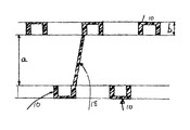
図10においては、内側の芯ラチス18の一部が示され、外側ラチス10の深さbに対する芯ラチスの幅aが示されている。
【図面の簡単な説明】
【図1】本発明によるバットの平面図。
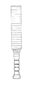
【図2】本発明によるバットの側面図。
【図3】図1の線3―3に沿った断面図。
【図4】図1の線3B−3Bに沿った断面図。
【図5】 3個のラチスを示すが、判り易くするために内側芯ラチスと一体である個所以外内側の横方向の支柱を除いて示す、バットの簡素化した3次元の分解図。
【図6】本発明によるバットの破断した部分等角図。
【図7】本発明の改善を示す、図3と類似の図面。
【図8】外側の2個のラチスを除いた、内側芯ラチスを示す、バットの部分的な等角図。
【図9】2個の外側ラチスと内側芯ラチスの破断して示す構造を追加した類似の図。
【図10】芯ラチスの特性を示すための、バットの極めて小さい部分の拡大した側断面図。
【符号の説明】
10 外側ラチス
11 空隙
12 内側横方向支柱
14 芯ラチス
16、18 柱
20 ウエッブ
22 打撃面の中央領域
50 オリフィス[0001]
BACKGROUND OF THE INVENTION
The present invention relates to a bat for playing games, in particular paddle tennis, tether ball, beach tennis, tennis balls and the like for playing similar games.
[0002]
[Prior art]
Although the thickness of such a bat is important from the standpoint of rigidity, it is recognized that consideration should be given to the mass of the bat as well as its balance for a good feel at impact.
[0003]
Therefore, the pattern includes a handle and a head, the head includes an unstressed monolithic perforated structure, and has a pair of spaced lattice structures, It has long been proposed to provide a bat in which the two outer surfaces of the lattice structure constitute the striking surface and the inner surfaces are joined together by a plurality of discrete transverse struts. In this specification, the term “lattice structure” (or lattice) refers to a lattice or lattice structure that is thin with respect to length or width, and is a structure that is perforated by a series of openings of various shapes. That means. In a particular form of the invention, the structure may be straight, curved, or other shape, and is a lattice of intersecting laths that can intersect at various angles.
[0004]
In a preferred embodiment of the present invention, two spaced apart lattices are formed by crossing laths, intermittent lateral struts straddling the corresponding crossing portions of the lath, and extending around the lattice, and a handle is attached thereto. Are joined by the outer frame or edge of the head of the bat.
[0005]
Further, according to the present invention, ones with web with voids lattice-shaped striking face (webbed) Tosureba well, it is more preferable that the checkerboard pattern (checkered pattern) alternating gap as-out with web . This bat has a striking head that can be expressed as a double lattice structure in which the outer surfaces of two lattices constitute a striking surface.
[0006]
This structure allows the racket head to be relatively thick and provides a high degree of rigidity due to the depth or width of the "frame" extending around the percussion head.
[0007]
Inside the butt other internal lateral struts is a middle empty, therefore, it is relatively lightweight. A bat of this construction is described in U.S. Pat. No. 4,411,427.
[0008]
[Problems to be solved by the invention]
It is an object of the present invention to provide a perforated type bat that has superior stiffness than that provided by a double lattice design bat as described above.
[0009]
[Means for Solving the Problems]
According to the present invention, a bat incorporating a monolithic and stress-free striking head having a pair of spaced outer lattices, the outer surface of the outer lattice constituting the striking surface of the striking head, and the two outer lattices being A bat joined by a third inner “core lattice” covered and protected by the two outer lattices is provided.
[0010]
As used herein, the term “core lattice” refers to at least one longitudinal component and one transverse element that straddle the striking head of the bat and, together with the outer edge of the bat, form such a “core lattice”. It includes a structure composed of directional components.
[0011]
However, the term core lattice is composed of components that extend in only one direction and straddle the striking head so that the components do not cross each other or only one such component strikes. A structure straddling the head may also be included.
[0012]
The core lattice is characterized by relatively few components compared to the two outer lattices.
[0013]
In a preferred form of the invention, the outer lattice has a gap that is at least 25 mm in size when measured from any direction across the gap in order to reduce the uneven “bounce” of the ball at impact. Or the gap is not included. However, the core lattice components may include voids that are preferably at least 40 mm in size between the components.
[0014]
Another feature of the present invention is that the webbed sections of the internal components that make up the core lattice are relatively thin compared to the elements that make up the outer lattice.
[0015]
In a preferred embodiment of the present invention, the thickness of the lath constituting the outer lattice is at least about 1.5 mm to 2 mm so as to be strong enough to withstand damage when the ball is hit during play. However, the thickness of the web portion of the inner core lattice is substantially thinner, on the order of about 0.75 mm.
[0016]
In a preferred embodiment of the present invention, the core lattice includes at least two longitudinal components and two lateral components.
[0017]
The latter of these components can coincide with the intersections of the two outer lattices and can be positioned symmetrically with respect to the head structure.
[0018]
The other intersections of the spaced apart outer lattices may be joined by intermittent lateral struts, the components being found to coincide with a row of struts, and in fact the elements have a connecting web in between It can consist of strut rows. The web may be on the order of 0.75 mm so that the mass of the bat is kept to a minimum.
[0019]
One design feature of this type of bat is that the two outer lattices are designed to be strong and powerful enough to withstand any damage caused by hitting the ball during play. It is. However, these outer lattices protect and cover the core lattice components, which provide additional great rigidity to the bat, albeit relatively thin. If the core lattice components are not protected by the outer lattice in this way, they are quickly damaged, and therefore not only because of their relative thinness, but are usually relatively widely separated. The ball penetrates very deep below the level of the plane of the outer edge of the impacted lattice and impacts against the side rather than the edge of the element, thus exerting lateral stress on the element Susceptible to damage from possible ball hits.
[0020]
In a preferred form of the invention, the core lattice includes a zone surrounded by the core lattice components at the center or sweet spot of the bat to provide additional stiffness and strength in this zone. Surprisingly, it has been found that this zone can also produce distinctive and distinctive impact sounds. There may be a difference in pitch when the ball is hit in this central area as compared to other areas of the bat head outside this central zone.
[0021]
The pitch of such sounds varies with the area of the central zone surrounded by the core lattice components, as well as the pitch of the impact sound when the ball hits the area outside the central zone. It may also vary depending on the area enclosed by the core lattice components (and possibly the surrounding rim).
[0022]
A variation of the present invention introduces another component in the central zone and divides this region into relatively smaller zones compared to the zone in the outer region, and the impact sound is pitched if the ball hits this region. Is relatively high.
[0023]
Components that straddle the central zone do not straddle the entire bat head, but straddle only selected areas of the central zone.
[0024]
The lattice of the striking surface is preferably webs alternately, and the web on one surface preferably forms a staggered checkered pattern with respect to the web on the other surface.
[0025]
One or more holes or openings in the center of such webbed portions are formed in the webbed portion of the core lattice component located between the internal lateral struts connecting the two outer lattices. It has been found that, if provided, it saves weight and does not significantly affect the structural strength or stiffness of the element.
[0026]
Such holes or openings provide a bearing surface that contacts the adjacent structure of the mold and supports it in a closed position while the bat is being molded, thus helping to extend the life of the tool making the bat. .
[0027]
The preferred form of the invention provides one or more holes or openings in the center of each webbed portion of the core lattice component.
[0028]
DETAILED DESCRIPTION OF THE INVENTION
Embodiments of the present invention will be described below with reference to the accompanying drawings.
[0029]
The bat of the present invention has a pair of spaced
[0030]
The inner surfaces of the two outer lattices are joined and their intersections are joined by internal lateral struts 12.
[0031]
The
[0032]
The intersection of the longitudinal and transverse columns defines a
[0033]
In FIG. 7, the
[0034]
It will be appreciated that more than one such orifice may be provided.
[0035]
In FIG. 8, the basic skeleton structure of the bat is shown, and in FIG. 9, a part of the two outer lattices is shown on one side of the core lattice composed of the
[0036]
In FIG. 10, a part of the
[Brief description of the drawings]
FIG. 1 is a plan view of a bat according to the present invention.
FIG. 2 is a side view of a bat according to the present invention.
3 is a cross-sectional view taken along line 3-3 in FIG.
4 is a cross-sectional view taken along line 3B-3B in FIG.
FIG. 5 is a simplified three-dimensional exploded view of a bat showing three lattices, but excluding the inner lateral struts except where they are integral with the inner core lattice for clarity.
FIG. 6 is a fragmented isometric view of a bat according to the present invention.
7 is a drawing similar to FIG. 3, showing the improvement of the present invention.
FIG. 8 is a partial isometric view of the bat showing the inner core lattice with the two outer lattices removed.
FIG. 9 is a similar view to which a structure shown by breaking two outer lattices and an inner core lattice is added.
FIG. 10 is an enlarged side cross-sectional view of a very small portion of the bat to show the properties of the core lattice.
[Explanation of symbols]
DESCRIPTION OF
Claims (5)
Applications Claiming Priority (2)
| Application Number | Priority Date | Filing Date | Title |
|---|---|---|---|
| ZA971247 | 1997-02-14 | ||
| ZA97/1247 | 1997-02-14 |
Publications (2)
| Publication Number | Publication Date |
|---|---|
| JPH10263113A JPH10263113A (en) | 1998-10-06 |
| JP4004629B2 true JP4004629B2 (en) | 2007-11-07 |
Family
ID=25586224
Family Applications (1)
| Application Number | Title | Priority Date | Filing Date |
|---|---|---|---|
| JP07298998A Expired - Fee Related JP4004629B2 (en) | 1997-02-14 | 1998-02-16 | bat |
Country Status (6)
| Country | Link |
|---|---|
| US (1) | US5961404A (en) |
| EP (1) | EP0882476B1 (en) |
| JP (1) | JP4004629B2 (en) |
| AU (1) | AU728156B2 (en) |
| DE (1) | DE69823267T2 (en) |
| ZA (1) | ZA981104B (en) |
Families Citing this family (15)
| Publication number | Priority date | Publication date | Assignee | Title |
|---|---|---|---|---|
| KR200261717Y1 (en) * | 2001-09-17 | 2002-01-24 | 하웅수 | racket which has multi-use |
| NZ532683A (en) * | 2001-10-11 | 2005-11-25 | Woodworm Cricket Company Ltd | A sports bat including a handle, a blade with a hitting sweet spot, a toe, a pair of shoulders and one or more recesses |
| US20060223677A1 (en) * | 2002-08-27 | 2006-10-05 | Power Web International | Hand Exerciser |
| US7121983B1 (en) * | 2002-08-27 | 2006-10-17 | Power Web International | Hand exerciser |
| US7402117B2 (en) * | 2004-08-09 | 2008-07-22 | Kai-Ping Wang | Racket with a center of gravity approximate to a center of a rubber sheet |
| FR2880812B1 (en) * | 2005-01-20 | 2007-06-08 | Cornilleau Sa Ets | TABLE TENNIS RACKET |
| US20070191154A1 (en) * | 2006-02-10 | 2007-08-16 | Genereux Dana A | Racquet sport apparatus & method |
| WO2009125329A1 (en) * | 2008-04-07 | 2009-10-15 | Prince Sports, Inc. | An improved sports racquet structure |
| CA2725327A1 (en) * | 2008-05-24 | 2009-12-03 | Mongoose Cricket Limited | A cricket sports bat |
| CN106794370A (en) | 2014-08-28 | 2017-05-31 | 莱姆派特运动管理有限责任公司 | Racket for carrying out ball game |
| US10377093B2 (en) * | 2015-01-06 | 2019-08-13 | Gear Box | Panel structure with foam core and methods of manufacturing articles using the panel structure |
| US20170021248A1 (en) * | 2015-07-24 | 2017-01-26 | Indian Industries, Inc. | Paddle with internal ribs |
| WO2020144635A1 (en) * | 2019-01-10 | 2020-07-16 | Limpet Sports Management B.V. | A bat for playing ball games |
| US20210252357A1 (en) * | 2019-05-15 | 2021-08-19 | Feng-Yu Lee | Pickleball paddle |
| US20200360781A1 (en) * | 2019-05-15 | 2020-11-19 | John Charles Marcin | Target for a Sport Training Device |
Family Cites Families (9)
| Publication number | Priority date | Publication date | Assignee | Title |
|---|---|---|---|---|
| GB1242704A (en) * | 1968-12-10 | 1971-08-11 | Avon Rubber Company Ltd | Improvements in sporting goods |
| CA879243A (en) * | 1969-01-03 | 1971-08-24 | Liard Maurice | Stick for ice ball game |
| US3879250A (en) * | 1973-05-03 | 1975-04-22 | Jr Paul B Rankin | Method of manufacturing paddle ball racquets |
| US4079935A (en) * | 1973-11-09 | 1978-03-21 | Zimm-Zamm Aktiengesellschaft | Sports equipment |
| US3934876A (en) * | 1974-04-15 | 1976-01-27 | Norman S. Blodgett | Game racket |
| US4411427A (en) * | 1980-06-23 | 1983-10-25 | Alfred Baumgartner | Bat for playing games |
| ATE26922T1 (en) * | 1983-09-07 | 1987-05-15 | Mohammed Hussein Lotfy | RACKET FOR A BALL GAME. |
| FR2615402A3 (en) * | 1987-05-18 | 1988-11-25 | Dubois Jean Paul | Table-tennis bat made from composite aramid and carbon materials |
| US5150896A (en) * | 1992-03-03 | 1992-09-29 | David Holmes | Game racket with incurvate contact surfaces |
-
1998
- 1998-02-10 AU AU53876/98A patent/AU728156B2/en not_active Ceased
- 1998-02-10 US US09/021,099 patent/US5961404A/en not_active Expired - Lifetime
- 1998-02-11 DE DE69823267T patent/DE69823267T2/en not_active Expired - Lifetime
- 1998-02-11 ZA ZA981104A patent/ZA981104B/en unknown
- 1998-02-11 EP EP98300988A patent/EP0882476B1/en not_active Expired - Lifetime
- 1998-02-16 JP JP07298998A patent/JP4004629B2/en not_active Expired - Fee Related
Also Published As
| Publication number | Publication date |
|---|---|
| AU5387698A (en) | 1998-08-20 |
| ZA981104B (en) | 1998-08-20 |
| EP0882476A1 (en) | 1998-12-09 |
| DE69823267T2 (en) | 2005-08-18 |
| DE69823267D1 (en) | 2004-05-27 |
| EP0882476B1 (en) | 2004-04-21 |
| AU728156B2 (en) | 2001-01-04 |
| JPH10263113A (en) | 1998-10-06 |
| US5961404A (en) | 1999-10-05 |
Similar Documents
| Publication | Publication Date | Title |
|---|---|---|
| JP4004629B2 (en) | bat | |
| ES2315806T3 (en) | SPORTS RACKET WITH INSERTED ELEMENTS TO ANCHOR THE ROPES. | |
| EP3185974B1 (en) | A bat for playing ball games | |
| US4076240A (en) | Hockey stick | |
| US5669826A (en) | Structure of golf club head | |
| US7585234B2 (en) | Lacrosse head having a transverse rail | |
| JP3821516B2 (en) | Golf club head | |
| US3934876A (en) | Game racket | |
| JP2006519050A (en) | Sports racket with frame opening | |
| JPH09154985A (en) | Golf club head | |
| US4079935A (en) | Sports equipment | |
| CN100457220C (en) | Racket for ball games and its producing method | |
| US8951150B2 (en) | Tennis racket including shock-absorber means | |
| US7806789B2 (en) | Sports racket | |
| US4076241A (en) | Sports racket | |
| JPH0224553B2 (en) | ||
| US5277422A (en) | Games racket frame | |
| US7077767B2 (en) | Racket for ball games and production process | |
| US20210331050A1 (en) | Bat for playing ball games | |
| IT201900005166A1 (en) | FENCED MULTIPURPOSE FIELD AND METHOD FOR REALIZING THE SAME | |
| JP3106250U (en) | Golf club head | |
| EP1060767A2 (en) | Improved games racket | |
| JP3068047U (en) | racket | |
| JPS6340490Y2 (en) | ||
| JPH0588152B2 (en) |
Legal Events
| Date | Code | Title | Description |
|---|---|---|---|
| A621 | Written request for application examination |
Free format text: JAPANESE INTERMEDIATE CODE: A621 Effective date: 20041126 |
|
| A131 | Notification of reasons for refusal |
Free format text: JAPANESE INTERMEDIATE CODE: A131 Effective date: 20070112 |
|
| A601 | Written request for extension of time |
Free format text: JAPANESE INTERMEDIATE CODE: A601 Effective date: 20070330 |
|
| A602 | Written permission of extension of time |
Free format text: JAPANESE INTERMEDIATE CODE: A602 Effective date: 20070404 |
|
| A521 | Written amendment |
Free format text: JAPANESE INTERMEDIATE CODE: A523 Effective date: 20070712 |
|
| TRDD | Decision of grant or rejection written | ||
| A01 | Written decision to grant a patent or to grant a registration (utility model) |
Free format text: JAPANESE INTERMEDIATE CODE: A01 Effective date: 20070724 |
|
| A61 | First payment of annual fees (during grant procedure) |
Free format text: JAPANESE INTERMEDIATE CODE: A61 Effective date: 20070822 |
|
| R150 | Certificate of patent or registration of utility model |
Free format text: JAPANESE INTERMEDIATE CODE: R150 |
|
| FPAY | Renewal fee payment (event date is renewal date of database) |
Free format text: PAYMENT UNTIL: 20100831 Year of fee payment: 3 |
|
| S111 | Request for change of ownership or part of ownership |
Free format text: JAPANESE INTERMEDIATE CODE: R313113 |
|
| FPAY | Renewal fee payment (event date is renewal date of database) |
Free format text: PAYMENT UNTIL: 20100831 Year of fee payment: 3 |
|
| R360 | Written notification for declining of transfer of rights |
Free format text: JAPANESE INTERMEDIATE CODE: R360 |
|
| R360 | Written notification for declining of transfer of rights |
Free format text: JAPANESE INTERMEDIATE CODE: R360 |
|
| R371 | Transfer withdrawn |
Free format text: JAPANESE INTERMEDIATE CODE: R371 |
|
| FPAY | Renewal fee payment (event date is renewal date of database) |
Free format text: PAYMENT UNTIL: 20100831 Year of fee payment: 3 |
|
| FPAY | Renewal fee payment (event date is renewal date of database) |
Free format text: PAYMENT UNTIL: 20100831 Year of fee payment: 3 |
|
| S111 | Request for change of ownership or part of ownership |
Free format text: JAPANESE INTERMEDIATE CODE: R313113 |
|
| FPAY | Renewal fee payment (event date is renewal date of database) |
Free format text: PAYMENT UNTIL: 20100831 Year of fee payment: 3 |
|
| R350 | Written notification of registration of transfer |
Free format text: JAPANESE INTERMEDIATE CODE: R350 |
|
| FPAY | Renewal fee payment (event date is renewal date of database) |
Free format text: PAYMENT UNTIL: 20110831 Year of fee payment: 4 |
|
| FPAY | Renewal fee payment (event date is renewal date of database) |
Free format text: PAYMENT UNTIL: 20130831 Year of fee payment: 6 |
|
| R250 | Receipt of annual fees |
Free format text: JAPANESE INTERMEDIATE CODE: R250 |
|
| R250 | Receipt of annual fees |
Free format text: JAPANESE INTERMEDIATE CODE: R250 |
|
| LAPS | Cancellation because of no payment of annual fees |