しかしながら、このようなジューサーにおいては、前記投入口の短径の寸法によって投入可能なジュース材料の大きさが決まるため、人参等の棒状のジュース材料を投入する場合、余り太いものを投入することができず、このため、太いジュース材料を投入する場合、適宜切断して投入する必要があり、ジュース材料を丸ごと投入することができないという問題があった。また、このようなジューサーにおいては、ジュース材料が前記カッターの回転中心からずれた位置に押し付けられるため、前記カッターや電動機に偏った応力が加わってしまい、異常振動が生じてしまうという虞があった。そして、このような異常振動がジューサーの本体に伝わると、ジューサー全体が自走してしまうという虞があった。
However, in such a juicer, the size of the juice material that can be introduced is determined by the short diameter dimension of the inlet, so when a rod-like juice material such as carrot is introduced, a thicker one may be introduced. For this reason, when a thick juice material is added, it is necessary to cut and input appropriately, and there is a problem that the whole juice material cannot be input. Further, in such a juicer, since the juice material is pressed at a position deviated from the rotation center of the cutter, there is a risk that stress is applied to the cutter and the electric motor, and abnormal vibration is generated. . When such abnormal vibration is transmitted to the main body of the juicer, there is a risk that the entire juicer may be self-propelled.
本発明は以上の問題点を解決し、太い棒状の食材を丸ごとすり下ろすことができると共に、駆動系に偏った応力が加わらないジューサーを提供することを目的とする。
An object of the present invention is to solve the above-described problems and to provide a juicer that can squeeze a whole thick bar-like food material and that does not apply biased stress to the drive system.
本発明の請求項1に記載のジューサーは、電動機が内蔵された本体と、前記電動機によって回転させられると共に前記本体の上部に露出する回転子と、前記本体の上部に対して着脱自在に取り付けられる受け部材と、前記回転子に対して着脱自在に取り付けられると共に前記受け部材内に露出する濾過体と、この濾過体の下部中央に固定された下ろし刃体と、前記受け部材に対して着脱自在に取り付けられると共に前記濾過体及び下ろし刃体を覆う蓋体と、前記下ろし刃体に対向して前記蓋体に設けられた筒状投入口と、この筒状投入口に対して軸方向に挿入されると共に底部に複数のスパイク部が形成された押し棒とを有するジューサーにおいて、前記筒状投入口及び押し棒を略円筒状に形成し、前記筒状投入口が前記下ろし刃体と略同軸となるように前記筒状投入口を前記蓋体に形成すると共に、前記筒状投入口の内面又は前記押し棒の外面の一方に突条を形成し、他方に前記突条に対応する凹溝を形成したものである。
The juicer according to claim 1 of the present invention is detachably attached to a main body having a built-in electric motor, a rotor that is rotated by the electric motor and exposed to the upper portion of the main body, and an upper portion of the main body. A receiving member, a filter body that is detachably attached to the rotor and exposed in the receiving member, a lowering blade body fixed to the lower center of the filter body, and a removable member to the receiving member A lid body that covers the filter body and the lowering blade body, a cylindrical insertion port provided in the lid body so as to face the lowering blade body, and an axial insertion with respect to the cylindrical insertion port in juicer and a push rod having a plurality of spikes on the bottom is formed while being, said tubular inlet and the push rod is formed in a substantially cylindrical shape, the blade body and substantially coaxially the tubular inlet is down the The tubular inlet so as to form on the lid, while the form of the protrusion of the outer surface of the inner or the push rod of the cylindrical inlet, the grooves corresponding to the ridges on the other Formed.
また、本発明の請求項2に記載のジューサーは、請求項1において、前記筒状投入口の内径を前記下ろし刃体における刃形成部分の外径と略同じに形成したものである。
A juicer according to a second aspect of the present invention is the juicer according to the first aspect, wherein an inner diameter of the cylindrical charging port is formed substantially the same as an outer diameter of a blade forming portion of the lowering blade body.
また、本発明の請求項3に記載のジューサーは、電動機が内蔵された本体と、前記電動機によって回転させられると共に前記本体の上部に露出する回転子と、前記本体の上部に対して着脱自在に取り付けられる受け部材と、前記回転子に対して着脱自在に取り付けられると共に前記受け部材内に露出する濾過体と、この濾過体の下部中央に固定された下ろし刃体と、前記受け部材に対して着脱自在に取り付けられると共に前記濾過体及び下ろし刃体を覆う蓋体と、前記下ろし刃体に対向して前記蓋体に設けられた筒状投入口と、この筒状投入口に対して軸方向に挿入されると共に底部に複数のスパイク部が形成された押し棒とを有するジューサーにおいて、前記筒状投入口及び押し棒を、それぞれ相似な略正多角筒状に形成し、前記筒状投入口の中心から各内面までの距離を、前記押し棒の中心から各外面までの距離よりも長く、且つ前記押し棒の中心から各角部までの距離よりも短く形成すると共に、前記筒状投入口が前記下ろし刃体と略同軸となるように前記筒状投入口を前記蓋体に形成したものである。
According to a third aspect of the present invention, there is provided a juicer that is detachably attached to a main body having a built-in electric motor, a rotor that is rotated by the electric motor and exposed to the upper portion of the main body, and an upper portion of the main body. A receiving member to be attached, a filter body that is detachably attached to the rotor and exposed in the receiving member, a lowering blade body fixed to a lower center of the filter body, and the receiving member A lid body that is detachably attached and covers the filter body and the lowering blade body, a cylindrical inlet provided in the lid body so as to face the lowering blade body, and an axial direction with respect to the cylindrical inlet in juicer and a push rod having a plurality of spikes on the bottom is formed while being inserted into, the tubular inlet and the push rod, to form respectively similar and substantially regular polygonal tubular, the tubular-on The distance from the center of to each inner surface is longer than the distance from the center of the push rod to the outer surface, and thereby shorter than the distance from the center of the push rod to the respective corner portions, the tubular inlet The cylindrical inlet is formed in the lid so as to be substantially coaxial with the lowering blade body.
また、本発明の請求項4に記載のジューサーは、請求項3において、前記筒状投入口の内面を、これを前記下ろし刃体に投影した投影範囲が、前記下ろし刃体における刃形成部分の外径に対して内接する範囲と外接する範囲との間になるように形成したものである。
The juicer according to claim 4 of the present invention is the juicer according to claim 3, wherein the projection range obtained by projecting the inner surface of the cylindrical insertion port onto the lowering blade body is the blade forming portion of the lowering blade body. It is formed so as to be between a range inscribed with respect to the outer diameter and a range inscribed with the outer diameter.
本発明の請求項1に記載のジューサーは、以上のように構成することにより、前記本体上部に受け部材を取り付けた後、前記回転子に濾過体及び下ろし刃体を取り付け、前記受け部材蓋体を取り付け、前記蓋体を前記電動機を駆動することで前記回転子及びこの回転子に取り付けられた下ろし刃体を回転させ、前記筒状投入口から食材を投入して前記押し棒で前記食材を前記下ろし刃体に押し付けることで前記食材が前記下ろし刃体によってすり下ろされ、このすり下ろされた食材が濾過体によってジュースと滓に分離される。このとき、前記筒状投入口の開口面積が広くできるので、前記筒状投入口に投入可能な棒状食材の太さを太くすることができるばかりでなく、前記棒状食材が前記下ろし刃体に対して前記押し棒によって略同軸状に押し付けられるので、前記電動機や回転子、下ろし刃体等の駆動系に偏った応力が加わらないようにすることができる。また、前記押し棒の前記筒状投入口に対する回転は、前記突条及び凹溝によって阻止することができる。更に、前記棒状食材が前記下ろし刃体に連れ回ることを防止することができる。
The juicer according to claim 1 of the present invention is configured as described above, and after the receiving member is attached to the upper part of the main body, the filter body and the lowering blade body are attached to the rotor, and the receiving member lid body The rotor and the lower blade attached to the rotor are rotated by driving the electric motor with the lid body, the food material is charged from the cylindrical charging port, and the food material is loaded with the push rod. The food material is slid down by the lowering blade body by being pressed against the lowering blade body, and the slid down food material is separated into juice and straw by the filter body. At this time, since the opening area of the cylindrical charging port can be widened, not only can the thickness of the rod-shaped food material that can be charged into the cylindrical charging port be increased, but the rod-shaped food material can be used with respect to the lowering blade body. Therefore, it is possible to prevent the biased stress from being applied to the drive system such as the electric motor, the rotor, and the lowering blade body. Further, the rotation of the push rod with respect to the cylindrical insertion port can be prevented by the protrusion and the groove. Furthermore, it can prevent that the said rod-shaped foodstuff follows the said lowering blade body.
また、本発明の請求項2に記載のジューサーは、以上のように構成することにより、前記筒状投入口から投入される棒状食材を、下ろし刃体全体を使ってすり下ろすことができる。
In addition, the juicer according to claim 2 of the present invention is configured as described above, so that the rod-shaped food material fed from the cylindrical charging port can be lowered using the entire lowering blade body.
また、本発明の請求項3に記載のジューサーは、以上のように構成することにより、前記筒状投入口の開口面積が広くできるので、前記筒状投入口に投入可能な棒状食材の太さを太くすることができるばかりでなく、前記棒状食材が前記下ろし刃体に対して前記押し棒によって略同軸状に押し付けられるので、前記電動機や回転子、下ろし刃体等の駆動系に偏った応力が加わらないようにすることができる。また、前記押し棒の前記筒状投入口に対する回転は、これら押し棒及び筒状投入口が、それぞれ相似な略正多角筒状に形成されて、前記押し棒の角部が前記筒状投入口の内面に当接することによって阻止することができる。更に、前記棒状食材が前記下ろし刃体に連れ回ることを防止することができる。
In addition, the juicer according to claim 3 of the present invention is configured as described above, so that the opening area of the cylindrical charging port can be widened. Since the rod-shaped foodstuff is pressed substantially coaxially by the push rod against the lowering blade body, the stress biased in the drive system such as the electric motor, the rotor, the lowering blade body, etc. Can be added. In addition, the rotation of the push rod with respect to the cylindrical charging port is such that the push rod and the cylindrical charging port are formed in a substantially regular polygonal tube shape similar to each other , and the corner of the push bar is the cylindrical charging port. can be the inner surface blocked by abutment to Rukoto. Furthermore, it can prevent that the said rod-shaped foodstuff follows the said lowering blade body.
また、本発明の請求項4に記載のジューサーは、以上のように構成することにより、前記筒状投入口から投入される棒状食材を、下ろし刃体全体を使ってすり下ろすことができる。
In addition, the juicer according to claim 4 of the present invention is configured as described above, so that the rod-shaped food material fed from the cylindrical charging port can be slid down using the entire lowering blade body.
以下、本発明の第一の実施形態について、図1乃至図5に基づいて説明する。1はジューサーである。このジューサー1は、本体2と、この本体2の後述する回転子13に対して着脱自在に取り付けられる下ろし体3と、前記本体2の上部に対して着脱自在に取り付けられる受け部材4と、この受け部材4の上部に対して着脱自在に取り付けられる蓋体5から構成されている。
Hereinafter, a first embodiment of the present invention will be described with reference to FIGS. 1 to 5. 1 is a juicer. The juicer 1 includes a main body 2, a lowering body 3 that is detachably attached to a rotor 13 (to be described later) of the main body 2, a receiving member 4 that is detachably attached to the upper portion of the main body 2, and It is comprised from the cover body 5 attached to the upper part of the receiving member 4 so that attachment or detachment is possible.
前記本体2を構成するケーシング6の上部には膨出部7が形成されていると共に、この膨出部7の略中央に貫通孔8が形成されている。そして、前記ケーシング6内部における前記膨出部7の下方には、電動機9が吊り下げ状態で固定されていると共に、この電動機9のシャフト10が前記貫通孔8から前記ケーシング6外に突出している。なお、前記電動機9のシャフト10の下端には、ファン11が取り付けられていると共に、このファン11と対向して、前記ケーシング6の下部に通気孔12が形成されている。また、前記電動機9のシャフト10の上端には、回転子13が固定されている。そして、この回転子13には、前記下ろし体3が着脱自在に取り付けられている。なお、14は図示しない安全スイッチを作動させるための操作子である。
A bulging portion 7 is formed at the upper portion of the casing 6 constituting the main body 2, and a through hole 8 is formed at the approximate center of the bulging portion 7. An electric motor 9 is fixed in a suspended state below the bulging portion 7 in the casing 6, and a shaft 10 of the electric motor 9 projects out of the casing 6 from the through hole 8. . A fan 11 is attached to the lower end of the shaft 10 of the electric motor 9, and a vent hole 12 is formed in the lower portion of the casing 6 so as to face the fan 11. A rotor 13 is fixed to the upper end of the shaft 10 of the electric motor 9. The lower body 3 is detachably attached to the rotor 13. Reference numeral 14 denotes an operator for operating a safety switch (not shown).
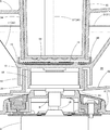
前記下ろし体3は、基部15と、この基部15の上面に固定された下ろし刃体16と、前記基部15の上部に設けられた略漏斗形状の濾過体17とで構成されている。そして、前記基部15は、前記回転子13に対して係合する内側リブ18と、この内側リブ18の外側に間隔を有して形成された外側リブ19とを有している。また、前記下ろし刃体16は、円盤状の鋼板の表面に多数の下ろし刃を形成したものであり、前記下ろし体3を前記回転子13に取り付けた状態において、この回転子13、ひいては前記電動機9のシャフト10と略同軸となるように前記基部15に対して固定されている。更に、前記下ろし刃体16の周囲には、この下ろし刃体16と一体に、複数の破砕突起20が等角度間隔で略環状に配列して形成されている。なお、これらの破砕突起20の配列は、前記下ろし刃体16と同心である。そして、前記破砕突起20の上端は、前記受け部材4に蓋体5を取り付けた状態における後述する筒状投入口34の下端の高さよりも高くなるように形成されている。また、前記受け部材4に蓋体5を取り付けた状態における筒状投入口34の外面から前記破砕突起20の内面までの距離が、前記受け部材4に蓋体5を取り付けた状態における後述する押し棒35の下端から前記下ろし刃体16までの距離よりも短くなるように、前記破砕突起20は前記下ろし刃体16に対して一体に形成されている。また、前記濾過体17は、前記取付部15と一体に形成された枠部21と、多数の小孔が形成された鋼板から成る濾過板22とから構成されている。更に、前記枠部21の上部には、下方に延びる略環状のリブ23が一体に形成されている。
The lowering body 3 includes a base portion 15, a lowering blade body 16 fixed to the upper surface of the base portion 15, and a substantially funnel-shaped filter body 17 provided on the upper portion of the base portion 15. The base portion 15 has an inner rib 18 that engages with the rotor 13 and an outer rib 19 that is formed outside the inner rib 18 with a gap. Further, the lowering blade body 16 is formed by forming a number of lowering blades on the surface of a disk-shaped steel plate. When the lowering body 3 is attached to the rotor 13, the rotor 13 and thus the electric motor 9 is fixed to the base 15 so as to be substantially coaxial with the shaft 10. Further, a plurality of crushing protrusions 20 are formed around the lowering blade body 16 so as to be integrated with the lowering blade body 16 and arranged in a substantially annular shape at equal angular intervals. The arrangement of the crushing protrusions 20 is concentric with the lowering blade body 16. Then, the upper end of the crushing projection 20 is formed to be higher than the height of the lower end of a cylindrical inlet 34 to be described later in a state where the lid 5 is attached to the receiving member 4. Further, the distance from the outer surface of the cylindrical insertion port 34 to the inner surface of the crushing protrusion 20 in a state where the lid body 5 is attached to the receiving member 4 is the pressing force described later in the state where the lid body 5 is attached to the receiving member 4. The crushing protrusion 20 is formed integrally with the lowering blade body 16 so as to be shorter than the distance from the lower end of the bar 35 to the lowering blade body 16. The filter body 17 includes a frame portion 21 formed integrally with the mounting portion 15 and a filter plate 22 made of a steel plate in which a large number of small holes are formed. Further, a substantially annular rib 23 extending downward is integrally formed on the upper portion of the frame portion 21.
前記受け部材4は、全体として上方が開放した略器状に形成されている。また、前記受け部材4は、前記本体2の上部に取り付けられた状態において、前記回転子13が露出する貫通孔24が形成された底壁25と、前記貫通孔24の縁から上方に延びると共に前記回転子13の周囲を覆うように前記底壁25と一体に形成された略円筒状のリブ26と、前記回転子13に前記下ろし体3が取り付けられた状態において、この下ろし体3の周囲を覆うように、前記底壁25と一体に形成された略円筒状の側壁27が設けられている。なお、前記下ろし体3を前記回転子13に取り付けた状態において、前記リブ26は、前記基部15の内側リブ18の外側で且つ前記外側リブ19の内側に位置すると共に、前記基部15に対して衝突しない程度の高さに形成されている。また、前記側壁27は、その高さが、前記回転子13に前記下ろし体3が取り付けられた状態における前記リブ23の下端よりも高く、且つ前記下ろし体3の上端よりも低くなるように形成されている。そして、前記底壁25及び側壁27によって囲まれた空間が集液室28となると共に、後述する遠心分離されたジュースを前記集液室28からジュース容器Sに注出させる注出路29が形成されている。また、前記側壁27の外周には、後述する遠心分離された食材の滓を溜める貯滓部30が形成されている。なお、31は筒状部であり、この筒状部31内に前記操作子14を押圧するための操作杆32が上下方向に移動可能に設けられている。また、33は前記蓋体5を前記受け部材4に取り付けるためのフックである。
The receiving member 4 is formed in a substantially container shape whose upper part is open as a whole. The receiving member 4 is attached to the upper portion of the main body 2 and extends upward from a bottom wall 25 in which a through hole 24 through which the rotor 13 is exposed is formed, and an edge of the through hole 24. In the state where the substantially cylindrical rib 26 formed integrally with the bottom wall 25 so as to cover the periphery of the rotor 13 and the lowering body 3 attached to the rotor 13, the periphery of the lowering body 3 A substantially cylindrical side wall 27 formed integrally with the bottom wall 25 is provided. In the state where the lowering body 3 is attached to the rotor 13, the rib 26 is located outside the inner rib 18 of the base portion 15 and inside the outer rib 19, and with respect to the base portion 15. It is formed so as not to collide. The side wall 27 is formed such that its height is higher than the lower end of the rib 23 in a state where the lowering body 3 is attached to the rotor 13 and lower than the upper end of the lowering body 3. Has been. A space surrounded by the bottom wall 25 and the side wall 27 serves as a liquid collection chamber 28, and a pouring path 29 is formed for pouring the juice, which will be described later, from the liquid collection chamber 28 into the juice container S. ing. In addition, a storage portion 30 for storing the sputum of the centrifuged food, which will be described later, is formed on the outer periphery of the side wall 27. Reference numeral 31 denotes a cylindrical portion, and an operating rod 32 for pressing the operating element 14 is provided in the cylindrical portion 31 so as to be movable in the vertical direction. Reference numeral 33 denotes a hook for attaching the lid 5 to the receiving member 4.
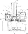
前記蓋体5には、この蓋体5を前記受け部材4に取り付けた状態において、前記下ろし刃体16と略同軸となるように、略円筒状の筒状投入口34が一体に形成されていると共に、この筒状投入口34に挿入されて上下に移動可能な略円筒状の押し棒35が設けられている。前記筒状投入口34の下端は、前記蓋体5を前記受け部材4に取り付けた状態において、前記下ろし刃体16との間に所定の間隔を有している。そして、前述したように、前記受け部材4に蓋体5を取り付けた状態において、前記筒状投入口34の下端の高さは、前記下ろし刃体16の上端の高さよりも低くなるように形成されている。また、前記受け部材4に蓋体5を取り付けた状態における筒状投入口34の外面から前記破砕突起20の内面までの距離が、前記筒状投入口34の下端から前記下ろし刃体16までの距離よりも短くなるように、前記筒状投入口34は形成されている。また、前記蓋体5を前記受け部材4に取り付けた状態において、前記筒状投入口34の下端開口を前記下ろし刃体16に投影すると、その範囲は、前記下ろし刃体16の前記下ろし刃が形成された部位と略一致するように(図5においては、前記下ろし刃が形成された部位よりも極僅かに狭くなるように)形成されている。なお、前記下ろし刃が形成された部位とは、前記下ろし刃体16の中心と、この中心から最も離れた位置にある下ろし刃との距離を半径とした、前記下ろし刃体16と略同心円となる範囲である。即ち、前記下ろし刃体16の下ろし刃が前記筒状投入口34の下端開口に略全て露出した状態となる。また、前記筒状投入口34の内面には、その軸方向と略平行に延びた突条36が形成されている。また、前記押し棒35の外側面には、前記筒状投入口34に形成された突条36に対応して、前記押し棒35の軸方向と略平行に延びた凹溝37が形成されている。更に、前記押し棒35の底部には、複数のスパイク部38が一体に形成されている。なお、このスパイク部38の下端が前記押し棒35の下端であり、この押し棒35を前記筒状投入口34に最大限押し込んだ状態における前記押し棒35の下端と前記筒状投入口34の下端が略面一となるように、前記筒状投入口34及び押し棒35は形成されている。なお、39は、前記蓋体5を前記受け部材4に取り付けた状態において、前記操作杆32によって押圧される押圧突起である。また、40は前記フック33と係合する掛け部である。
The lid 5 is integrally formed with a substantially cylindrical cylindrical inlet 34 so as to be substantially coaxial with the lower blade 16 in a state where the lid 5 is attached to the receiving member 4. In addition, a substantially cylindrical push bar 35 that is inserted into the cylindrical insertion port 34 and is movable up and down is provided. A lower end of the cylindrical charging port 34 has a predetermined interval with the lowering blade body 16 in a state where the lid body 5 is attached to the receiving member 4. As described above, in the state where the lid 5 is attached to the receiving member 4, the lower end of the cylindrical insertion port 34 is formed to be lower than the upper end of the lower blade 16. Has been. Further, the distance from the outer surface of the cylindrical insertion port 34 to the inner surface of the crushing projection 20 in a state where the lid 5 is attached to the receiving member 4 is from the lower end of the cylindrical insertion port 34 to the lowering blade body 16. The cylindrical inlet 34 is formed so as to be shorter than the distance. Further, when the lower end opening of the cylindrical insertion port 34 is projected onto the lowering blade body 16 in a state where the lid body 5 is attached to the receiving member 4, the range is that the lowering blade of the lowering blade body 16 is in the range. It is formed so as to substantially coincide with the formed portion (in FIG. 5, it is slightly narrower than the portion where the lowering blade is formed). Note that the portion where the lowering blade is formed refers to the center of the lowering blade body 16 and the lowering blade body 16 and a substantially concentric circle, the radius being the distance between the lowering blade located farthest from the center. It is a range. In other words, the lower blade of the lower blade body 16 is almost completely exposed at the lower end opening of the cylindrical charging port 34. Further, a ridge 36 extending substantially parallel to the axial direction is formed on the inner surface of the cylindrical charging port 34. Further, a concave groove 37 extending substantially parallel to the axial direction of the push rod 35 is formed on the outer surface of the push rod 35 corresponding to the protrusion 36 formed in the cylindrical insertion port 34. Yes. Further, a plurality of spike portions 38 are integrally formed at the bottom of the push bar 35. The lower end of the spike portion 38 is the lower end of the push rod 35, and the lower end of the push rod 35 and the tubular insert port 34 in a state where the push rod 35 is pushed into the tubular insert port 34 to the maximum extent. The cylindrical charging port 34 and the push bar 35 are formed so that the lower ends are substantially flush. Reference numeral 39 denotes a pressing projection pressed by the operating rod 32 in a state where the lid 5 is attached to the receiving member 4. Reference numeral 40 denotes a hook portion that engages with the hook 33.
次に、本発明の作用について説明する。まず、使用者は、前記本体2に対して前記受け部材4を取り付け、この受け部材4の貫通孔24から露出した回転子13に下ろし体3を取り付け、更にこの下ろし体3を覆うように前記受け部材4に前記蓋体5を取り付ける。この状態でスイッチSWを操作すると、前記電動機9が作動することで、この電動機9のシャフト10に取り付けられた回転子13、ひいてはこの回転子13に取り付けられた下ろし体3が回転する。なお、前記電動機9は、この電動機9のシャフト10の下端に取り付けられたファン11が回転することで前記通気孔12から導入された空気によって冷却される。そして、このように前記下ろし体3が回転している状態において、前記筒状投入口34から食材を投入し、前記押し棒35で押すことによって、この筒状投入口34から投入された食材が前記下ろし刃体16によってすり下ろされる。なお、前述したように、前記筒状投入口34が略円筒状に形成されていることで開口面積が最大限に確保できるので、この筒状投入口34に棒状の食材として代表的なものである人参を投入する場合、中型のものであれば丸ごと投入することが可能である。また、前述したように、前記筒状投入口34が前記下ろし刃体16と略同軸状であると共に、前記筒状投入口34の下端開口を前記下ろし刃体16に投影した範囲が、前記下ろし刃体16の前記下ろし刃が形成された部位と略一致するように形成されていることから、前記筒状投入口34から投入された食材を前記下ろし刃体16に対して同軸状に押し付けることが可能となり、前記下ろし刃体16に偏った応力が加わらないようにできると共に、前記下ろし刃体16の下ろし刃全体を使って食材をすり下ろすことが可能となるので、食材を効率よくすり下ろすことができる。なお、前記押し棒35は、前記筒状投入口34に対する軸回り方向の回転が前記突条36と凹溝37によって防止されるので、前記下ろし体3の回転に連れて、食材を介して前記押し棒35が回転してしまうことが防止されるので、この押し棒35によって押される食材が確実にすり下ろされる。また、前記押し棒35で押される食材は、前記押し棒35の底面に形成された前記スパイク部38が突き刺さることで、前記下ろし刃体16と連れ回ることが防止され、確実にすり下ろされる。
Next, the operation of the present invention will be described. First, the user attaches the receiving member 4 to the main body 2, attaches the lowering body 3 to the rotor 13 exposed from the through hole 24 of the receiving member 4, and further covers the lowering body 3 so as to cover the lowering body 3. The lid 5 is attached to the receiving member 4. When the switch SW is operated in this state, the electric motor 9 is operated, whereby the rotor 13 attached to the shaft 10 of the electric motor 9 and thus the lowering body 3 attached to the rotor 13 rotate. The electric motor 9 is cooled by the air introduced from the vent hole 12 as a fan 11 attached to the lower end of the shaft 10 of the electric motor 9 rotates. And in the state which the said lowering body 3 is rotating in this way, the food material thrown in from this cylindrical charging port 34 is thrown in by throwing in food material from the said cylindrical charging port 34, and pushing with the said push rod 35. It is lowered by the lowering blade 16. As described above, since the cylindrical charging port 34 is formed in a substantially cylindrical shape, the opening area can be secured to the maximum, so that the cylindrical charging port 34 is a typical bar-like food. When a certain carrot is thrown in, it can be thrown in if it is a medium size. Further, as described above, the cylindrical charging port 34 is substantially coaxial with the lowering blade body 16, and the range in which the lower end opening of the cylindrical charging port 34 is projected onto the lowering blade body 16 is the lowering blade. Since the blade 16 is formed so as to substantially coincide with the portion where the lowering blade is formed, the food material charged from the cylindrical charging port 34 is pressed coaxially against the lowering blade 16 It is possible to prevent biased stress from being applied to the lowering blade body 16, and it is possible to use the entire lowering blade of the lowering blade body 16 to slide down the food material, so that the food material can be efficiently lowered. be able to. The push bar 35 is prevented from rotating in the direction around the axis with respect to the cylindrical insertion port 34 by the protrusion 36 and the concave groove 37. Therefore, as the lowering body 3 rotates, the push rod 35 passes the food via the foodstuff. Since the push bar 35 is prevented from rotating, the food material pushed by the push bar 35 is surely lowered. Further, the food material pushed by the push rod 35 is prevented from being carried around with the lowering blade body 16 by being pierced by the spike portion 38 formed on the bottom surface of the push rod 35, and is reliably lowered.
そして、前記下ろし刃体16によってすり下ろされた食材は、前記下ろし体3の回転による遠心力によって前記濾過体17まで移動し、この濾過体17の濾過板22上でジュースと滓に分離され、ジュースのみ前記濾過板22の小孔を通過する。そして、この小孔を通過したジュースは、遠心力によって前記側壁27に衝突した後、重力によって前記底壁25に流下し、更に前記注出路29からジュース容器Sに注出される。なお、前述したように、前記下ろし体3の枠部21に略環状のリブ23が下方に延びて形成されており、このリブ23の下端が前記側壁27の上端よりも低くなるように形成されているため、前記濾過板22の小孔を通過したジュースは、前記リブ23よりも下方において前記側壁27に衝突することになるので、濾過されたジュースが前記側壁27を乗り越えることが防止される。また、前記濾過板22上に残った滓は、それ自体に遠心力が加わると共に、すり下ろされて前記濾過体17に移動してくる食材によって順次押されることで、前記貯滓部30に押し出される。
Then, the food material slung down by the lowering blade body 16 moves to the filter body 17 by centrifugal force due to the rotation of the lowering body 3, and is separated into juice and straw on the filter plate 22 of the filter body 17, Only the juice passes through the small holes of the filter plate 22. The juice that has passed through the small hole collides with the side wall 27 by centrifugal force, then flows down to the bottom wall 25 by gravity, and is further poured out into the juice container S from the pouring path 29. As described above, the substantially annular rib 23 is formed on the frame portion 21 of the lowering body 3 so as to extend downward, and the lower end of the rib 23 is formed to be lower than the upper end of the side wall 27. Therefore, since the juice that has passed through the small hole of the filter plate 22 collides with the side wall 27 below the rib 23, the filtered juice is prevented from getting over the side wall 27. . Further, the soot remaining on the filter plate 22 is subjected to centrifugal force on itself, and is pushed down to the storage part 30 by being pushed down sequentially by the ingredients that are moved down and moved to the filter body 17. It is.
そして、前述したように、前記押し棒35を前記筒状投入口34に最大限押し込んだ状態において、前記押し棒35の下端と前記下ろし刃体16との間に間隙が形成されているので、この間隙の寸法と略等しい厚さの略板状に下ろし残された食材の残余が生ずることになる。そして、この残余の大きな塊は遠心力によって前記下ろし体3の外方に飛び出すが、この残余の大きな塊は前記下ろし刃体16の周囲に一体形成された破砕突起20と衝突することによって、数mm程度に細かく破砕される。このため、この細かく破砕された残余が遠心力によって前記受け部材4或いは蓋体5と衝突したとしても、大きな衝突音が発生しない。なお、前述したように、前記破砕突起20の上端が前記筒状投入口34の下端よりも高く形成されているので、板状の残余が屈曲して前記破砕突起20を乗り越えることを防止することができる。更に、前記筒状投入口34及び押し棒35の下端から前記下ろし刃体16の上端までの間隙の寸法、即ちこれによって決まる残余の厚さよりも、前記筒状投入口34の下端部外面と前記破砕突起20の内面との間隙の寸法が小さく形成されているので、前記残余が板状のままでは物理的に通り得ず、これによって、前記板状の残余が破砕されない状態で前記破砕突起20を乗り越えることが確実に防止される。なお、前述したように、前記破砕突起20が鋼製の前記下ろし刃体16と一体に形成されていることで、前記破砕突起20が前記残余と衝突する衝撃に十分耐えることができる。
As described above, in the state where the push bar 35 is pushed into the cylindrical insertion port 34 to the maximum, a gap is formed between the lower end of the push bar 35 and the lowering blade body 16, The remaining food material is left in a substantially plate shape having a thickness substantially equal to the size of the gap. Then, this large remaining lump pops out of the lowering body 3 due to centrifugal force, and this large remaining lump collides with the crushing protrusions 20 integrally formed around the lowering blade body 16, so that It is crushed to about mm. For this reason, even if the finely crushed residue collides with the receiving member 4 or the lid body 5 by centrifugal force, no loud collision noise is generated. As described above, since the upper end of the crushing protrusion 20 is formed higher than the lower end of the cylindrical inlet 34, it is possible to prevent the plate-like residue from bending over the crushing protrusion 20. Can do. Further, the outer surface of the lower end portion of the cylindrical charging port 34 and the outer thickness determined from the dimension of the gap from the lower end of the cylindrical charging port 34 and the push bar 35 to the upper end of the lowering blade body 16, that is, the remaining thickness determined thereby. Since the size of the gap with the inner surface of the crushing protrusion 20 is formed small, the residue cannot be physically passed if it is in a plate shape, and thereby the crushing protrusion 20 in a state where the plate-like residue is not crushed. It is certainly prevented from getting over. As described above, the crushing protrusion 20 is formed integrally with the lower blade body 16 made of steel, so that the crushing protrusion 20 can sufficiently withstand the impact of colliding with the remainder.
以上のように本発明は、本体2と受け部材4と蓋体5を有し、前記蓋体5に形成された筒状投入口34から投入されて押し棒35で下ろし刃体16に押し付けられる食材を、前記本体2に内蔵された電動機9によって回転させられる回転子13に取り付けられる前記下ろし刃体16及び濾過体17ですり下ろし、ジュースと滓を遠心分離してジュースを得るジューサー1において、前記筒状投入口34及び押し棒35を略円筒状に形成し、前記筒状投入口34が前記下ろし刃体16と略同軸となるように前記蓋体5に形成すると共に、前記筒状投入口34の内面に突条36を形成し、この突条36に対応して前記押し棒35の外面に凹溝37を形成したことで、前記筒状投入口34の開口面積が広くできるので、比較的太い棒状食材を丸ごと前記筒状投入口34に投入することができ、また、前記棒状食材が前記下ろし刃体16に対して前記押し棒35によって略同軸状に押し付けられるので、前記電動機9や回転子13、下ろし刃体16等の駆動系に偏った応力が加わらず、異常振動が生じないようにすることができるばかりでなく、前記突条36及び凹溝37によって前記押し棒35の前記下ろし刃体16に対する連れ回りを阻止することができるものである。
As described above, the present invention includes the main body 2, the receiving member 4, and the lid 5, and is introduced from the cylindrical insertion port 34 formed in the lid 5 and pressed against the lowering blade 16 by the push rod 35. In the juicer 1 for squeezing the food with the lower blade 16 and the filter body 17 attached to the rotor 13 that is rotated by the electric motor 9 built in the main body 2 and centrifuging the juice and the straw to obtain the juice, The cylindrical charging port 34 and the push rod 35 are formed in a substantially cylindrical shape, and the cylindrical charging port 34 is formed in the lid body 5 so as to be substantially coaxial with the lowering blade body 16, and the cylindrical charging port By forming a protrusion 36 on the inner surface of the opening 34 and forming a concave groove 37 on the outer surface of the push bar 35 corresponding to the protrusion 36, the opening area of the cylindrical inlet 34 can be widened. A relatively thick rod-like food can be put into the cylindrical inlet 34, and Since the rod-like food material is pressed substantially coaxially by the push bar 35 against the lowering blade body 16, biased stress is not applied to the drive system of the electric motor 9, the rotor 13, the lowering blade body 16, etc. Not only can the vibration not be generated, but the protrusion 36 and the concave groove 37 can prevent the push rod 35 from rotating with respect to the lowering blade body 16.
また本発明は、前記筒状投入口34の内径を前記下ろし刃体16における刃形成部分の外径と略同じに形成したことで、前記筒状投入口34から投入される棒状食材を、下ろし刃体16の下ろし刃体全体を使って効率よくすり下ろすことができるものである。
In addition, the present invention lowers the rod-shaped food material charged from the cylindrical charging port 34 by forming the inner diameter of the cylindrical charging port 34 substantially the same as the outer diameter of the blade forming portion of the lower blade body 16. The blade 16 can be efficiently lowered using the whole lowering blade body.
更に本発明は、前記押し棒35の底部に複数のスパイク部38を形成したことで、前記筒状投入口34に投入された食材が前記下ろし刃体16に連れ回ることを防止し、確実にすり下ろすことができるものである。
Further, the present invention is formed by forming a plurality of spike portions 38 at the bottom of the push bar 35, thereby preventing the food material introduced into the cylindrical insertion port 34 from being carried around to the lowering blade body 16, and reliably It can be slid down.
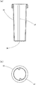
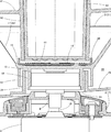
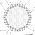
次に、本発明の第二の実施形態について、図6乃至図7に基づいて説明する。なお、前記第一の実施形態と共通する部分については、同一の符号を付し、その説明を省略する。ジューサー1は、本体2と、この本体2の後述する回転子13に対して着脱自在に取り付けられる下ろし体3と、前記本体2の上部に対して着脱自在に取り付けられる受け部材4と、この受け部材4の上部に対して着脱自在に取り付けられる蓋体41から構成されている。この蓋体41には、この蓋体41を前記受け部材4に取り付けた状態において、前記下ろし刃体16と略同軸となるように、略正八角筒状の筒状投入口42が一体に形成されていると共に、この筒状投入口42に挿入されて上下に移動可能な略正八角筒状の押し棒43が設けられている。前記筒状投入口42の下端は、前記蓋体41を前記受け部材4に取り付けた状態において、前記下ろし刃体16との間に所定の間隔を有している。そして、前述したように、前記受け部材4に蓋体41を取り付けた状態において、前記筒状投入口42の下端の高さは、前記下ろし刃体16の上端の高さよりも低くなるように形成されている。また、前記受け部材4に蓋体41を取り付けた状態における筒状投入口42の外面角部から前記破砕突起20の内面までの距離が、前記筒状投入口42の下端から前記下ろし刃体16までの距離よりも短くなるように、前記筒状投入口42は形成されている。また、前記蓋体41を前記受け部材4に取り付けた状態において、前記筒状投入口42の下端開口を前記下ろし刃体16に投影すると、その範囲が、前記下ろし刃体16の前記下ろし刃が形成された部位に対して、内接する範囲以上、外接する範囲以下となるように、(図7においては、内接する範囲よりも極僅かに広くなるように)前記筒状投入口42が形成されている。また、前記筒状投入口42の中心から各内面までの距離は、前記押し棒43の中心から各外面までの距離よりも長く、且つ前記押し棒43の中心から各角部までの距離よりも短くなるように形成されている。これによって、前記押し棒43を前記筒状投入口42内で軸回りに回動させようとしても、前記押し棒43の角部が前記筒状投入口42の内面に当接することで、回動を阻止することができる。更に、前記押し棒43の底部には、複数のスパイク部44が一体に形成されている。なお、このスパイク部44の下端が前記押し棒43の下端であり、この押し棒43を前記筒状投入口42に最大限押し込んだ状態における前記押し棒43の下端と前記筒状投入口42の下端が略面一となるように、前記筒状投入口42及び押し棒43は形成されている。
Next, a second embodiment of the present invention will be described with reference to FIGS. In addition, about the part which is common in said 1st embodiment, the same code | symbol is attached | subjected and the description is abbreviate | omitted. The juicer 1 includes a main body 2, a lowering body 3 that is detachably attached to a rotor 13 (to be described later) of the main body 2, a receiving member 4 that is detachably attached to an upper portion of the main body 2, and a receiving member 4 The lid 41 is detachably attached to the upper part of the member 4. The lid body 41 is integrally formed with a substantially regular octagonal cylindrical inlet 42 so as to be substantially coaxial with the lower blade body 16 in a state where the lid body 41 is attached to the receiving member 4. In addition, there is provided a substantially regular octagonal cylindrical push rod 43 which is inserted into the cylindrical insertion port 42 and is movable up and down. The lower end of the cylindrical insertion port 42 has a predetermined interval with the lowering blade body 16 in a state where the lid body 41 is attached to the receiving member 4. As described above, in the state where the lid 41 is attached to the receiving member 4, the lower end of the cylindrical insertion port 42 is formed to be lower than the upper end of the lower blade 16. Has been. In addition, the distance from the outer surface corner of the cylindrical insertion port 42 to the inner surface of the crushing projection 20 in the state where the lid 41 is attached to the receiving member 4 is the lower blade 16 from the lower end of the cylindrical insertion port 42. The cylindrical inlet 42 is formed so as to be shorter than the distance up to. Further, when the lower end opening of the cylindrical insertion port 42 is projected onto the lowering blade body 16 in a state where the lid body 41 is attached to the receiving member 4, the range of the lowering blade of the lowering blade body 16 is as follows. The cylindrical inlet 42 is formed so as to be greater than the inscribed range and less than the inscribed range with respect to the formed portion (in FIG. 7, it is slightly slightly wider than the inscribed range). ing. The distance from the center of the cylindrical inlet 42 to each inner surface is longer than the distance from the center of the push rod 43 to each outer surface, and more than the distance from the center of the push rod 43 to each corner. It is formed to be shorter. As a result, even if the push rod 43 is rotated about the axis in the cylindrical insertion port 42, the corner portion of the push rod 43 abuts on the inner surface of the cylindrical insertion port 42, thereby rotating the push rod 43. Can be prevented. Further, a plurality of spike portions 44 are integrally formed on the bottom portion of the push rod 43. The lower end of the spike 44 is the lower end of the push rod 43, and the lower end of the push rod 43 and the cylindrical input port 42 in a state where the push rod 43 is pushed into the cylindrical input port 42 to the maximum. The cylindrical inlet 42 and the push bar 43 are formed so that the lower ends are substantially flush.
次に、本発明の作用について説明する。まず、使用者は、前記本体2に対して前記受け部材4を取り付け、この受け部材4の貫通孔24から露出した回転子13に下ろし体3を取り付け、更にこの下ろし体3を覆うように前記受け部材4に前記蓋体41を取り付ける。この状態で図示しないスイッチを操作すると、前記電動機9が作動することで、この電動機9のシャフト10に取り付けられた回転子13、ひいてはこの回転子13に取り付けられた下ろし体3が回転する。そして、このように前記下ろし体3が回転している状態において、前記筒状投入口42から食材を投入し、前記押し棒43で押すことによって、この筒状投入口42から投入された食材が前記下ろし刃体16によってすり下ろされる。なお、前述したように、前記筒状投入口42が略正八角筒状に形成されていることで開口面積が略最大限に確保できるので、この筒状投入口42に棒状の食材として代表的なものである人参を投入する場合、中型のものであれば丸ごと投入することが可能である。また、前述したように、前記筒状投入口42が前記下ろし刃体16と略同軸状であると共に、前記筒状投入口42の下端開口を前記下ろし刃体16に投影した範囲が、前記下ろし刃体16の前記下ろし刃が形成された部位に対し、内接する範囲以上、外接する範囲以下となるように前記筒状投入口42が形成されていることから、現実的な形状の棒状食材を、前記下ろし刃体16の下ろし刃全体を用いてすり下ろすことができる。即ち、前記筒状投入口42の下端開口を前記下ろし刃体16に投影した範囲が前記下ろし刃の形成範囲に対して内接する場合、前記筒状投入口42の断面形状と同じ断面形状(現実には殆どあり得ない)の棒状食材が前記筒状投入口42に投入された場合でも、前記下ろし刃体16の下ろし刃全体を使って食材をすり下ろすことが可能となる一方、前記筒状投入口42の下端開口を前記下ろし刃体16に投影した範囲が前記下ろし刃の形成範囲に対して外接する場合、前記筒状投入口42の内面に内接する円筒状の棒状食材(これも、現実には殆どあり得ない)が前記筒状投入口42に投入された場合でも、前記下ろし刃体16の下ろし刃全体を使って食材をすり下ろすことが可能となるので、食材を効率よくすり下ろすことができる。また、前記筒状投入口42から投入された食材を前記下ろし刃体16に対して同軸状に押し付けることが可能となり、前記下ろし刃体16に偏った応力が加わらないようにできる。なお、前記押し棒43は、前記筒状投入口42に対する軸回り方向の回転が前記筒状投入口42の内面と前記押し棒43の角部との当接によって防止されるので、前記下ろし刃体16の回転に連れて、食材を介して前記押し棒43が回転してしまうことが防止されるので、この押し棒43によって押される食材が確実にすり下ろされる。また、前記押し棒43で押される食材は、前記押し棒43の底面に形成された前記スパイク部44が突き刺さることで、前記下ろし刃体16と連れ回ることが防止され、確実にすり下ろされる。
Next, the operation of the present invention will be described. First, the user attaches the receiving member 4 to the main body 2, attaches the lowering body 3 to the rotor 13 exposed from the through hole 24 of the receiving member 4, and further covers the lowering body 3 so as to cover the lowering body 3. The lid 41 is attached to the receiving member 4. When a switch (not shown) is operated in this state, the electric motor 9 is actuated to rotate the rotor 13 attached to the shaft 10 of the electric motor 9, and consequently the lowering body 3 attached to the rotor 13. And in the state which the said lowering body 3 is rotating in this way, foodstuffs thrown in from this cylindrical slot 42 are thrown in by throwing in foodstuffs from the said cylindrical slot 42, and pushing with the said push rod 43. It is lowered by the lowering blade 16. In addition, as described above, since the cylindrical charging port 42 is formed in a substantially regular octagonal cylindrical shape, the opening area can be ensured to a maximum extent. When putting a carrot that is a small one, it is possible to throw the whole carrot if it is a medium-sized one. Further, as described above, the cylindrical insertion port 42 is substantially coaxial with the lowering blade body 16, and the range in which the lower end opening of the cylindrical insertion port 42 is projected onto the lowering blade body 16 is the lowering portion. Since the cylindrical inlet 42 is formed so as to be not less than the inscribed range and not more than the circumscribed range with respect to the portion where the lowering blade of the blade body 16 is formed, a bar-shaped food material having a realistic shape can be obtained. The whole lowering blade of the lowering blade body 16 can be hung down. That is, when the range in which the lower end opening of the cylindrical inlet 42 is projected onto the lower blade body 16 is inscribed with respect to the forming range of the lower blade, the same cross-sectional shape as the cross-sectional shape of the cylindrical inlet 42 (actual Even when a rod-shaped food material (which is almost impossible) is introduced into the cylindrical inlet 42, it is possible to squeeze the food material using the whole lowering blade of the lowering blade body 16, while the cylindrical When the range in which the lower end opening of the inlet 42 is projected onto the lower blade body 16 circumscribes the formation range of the lower blade, a cylindrical rod-like food material that is inscribed in the inner surface of the cylindrical inlet 42 (also, In reality, it is almost impossible) even when it is put into the cylindrical slot 42, it is possible to slide down the ingredients using the whole lowering blade of the lowering blade body 16, so that the ingredients can be efficiently scoured. Can be lowered. In addition, it is possible to press the food material introduced from the cylindrical insertion port 42 coaxially against the lowering blade body 16, so that biased stress is not applied to the lowering blade body 16. The push bar 43 is prevented from rotating in the direction around the axis with respect to the cylindrical insertion port 42 by the contact between the inner surface of the cylindrical insertion port 42 and the corner of the push rod 43. As the body 16 rotates, the push bar 43 is prevented from rotating through the food material, so that the food material pushed by the push bar 43 is surely lowered. In addition, the food material pushed by the push rod 43 is prevented from being carried around with the lowering blade body 16 by being pierced by the spike portion 44 formed on the bottom surface of the push rod 43, and is reliably lowered.
以上のように本発明は、本体2と受け部材4と蓋体41を有し、前記蓋体41に形成された筒状投入口42から投入されて押し棒43で下ろし刃体16に押し付けられる食材を、前記本体2に内蔵された電動機9によって回転させられる回転子13に取り付けられる前記下ろし刃体16及び濾過体17ですり下ろし、ジュースと滓を遠心分離してジュースを得るジューサー1において、前記筒状投入口42及び押し棒43を略正八角筒状に形成すると共に、前記筒状投入口42が前記下ろし刃体16と略同軸となるように前記蓋体41に形成したことで、前記筒状投入口42の開口面積が広くできるので、比較的太い棒状食材を丸ごと前記筒状投入口42に投入することができ、また、前記棒状食材が前記下ろし刃体16に対して前記押し棒43によって略同軸状に押し付けられるので、前記電動機9や回転子13、下ろし刃体16等の駆動系に偏った応力が加わらず、異常振動が生じないようにすることができるばかりでなく、前記筒状投入口42の内面に前記押し棒43の角部が当接することによって前記押し棒43の前記下ろし刃体16に対する連れ回りを阻止することができるものである。
As described above, the present invention includes the main body 2, the receiving member 4, and the lid 41, and is inserted from the cylindrical insertion port 42 formed in the lid 41 and pressed against the lowering blade 16 by the push rod 43. In the juicer 1 for squeezing the food with the lower blade 16 and the filter body 17 attached to the rotor 13 that is rotated by the electric motor 9 built in the main body 2 and centrifuging the juice and the straw to obtain the juice, By forming the cylindrical charging port 42 and the push rod 43 in a substantially regular octagonal cylindrical shape, and forming the cylindrical charging port 42 in the lid body 41 so as to be substantially coaxial with the lowering blade body 16, Since the opening area of the cylindrical inlet 42 can be widened, a relatively thick bar-like food can be put into the cylindrical inlet 42, and the bar-like food can be pushed against the lowering blade body 16 Since it is pressed almost coaxially by the rod 43, The drive system such as the electric motor 9, the rotor 13, the lowering blade body 16, etc. can be applied with no biased stress to prevent abnormal vibrations, and the push rod is formed on the inner surface of the cylindrical inlet 42. When the corner portions of 43 come into contact with each other, it is possible to prevent the push rod 43 from being rotated with respect to the lowering blade body 16.
また本発明は、前記筒状投入口42の内面が、これを前記下ろし刃体16に投影した投影範囲が、前記下ろし刃体16における刃形成部分の外径に対して内接する範囲以上、外接する範囲以下となるように前記筒状投入口を形成したことで、現実的な形状の棒状食材を、前記下ろし刃体16の刃形成部分全体を用いて効率よくすり下ろすことができるものである。
Further, the present invention provides a method in which the inner surface of the cylindrical insertion port 42 is circumscribed more than a range in which a projection range in which the inner surface is projected onto the lower blade body 16 is inscribed with respect to an outer diameter of a blade forming portion of the lower blade body 16. By forming the cylindrical inlet so as to be less than or equal to the range, it is possible to efficiently squeeze the rod-shaped food material of a realistic shape using the entire blade forming portion of the lowering blade body 16 .
また本発明は、前記筒状投入口42の外面を、これを前記下ろし刃体16に投影した投影範囲が、前記下ろし刃体16の外径よりも小さくなるように形成したことで、前記筒状投入口42が前記濾過体17に対して干渉しないようにすることができるものである。
Further, the present invention is such that the outer surface of the cylindrical inlet 42 is formed so that a projection range in which the outer surface is projected onto the lower blade 16 is smaller than the outer diameter of the lower blade 16. The shape inlet 42 can be prevented from interfering with the filter body 17.
更に本発明は、前記押し棒43の底部に複数のスパイク部44を形成したことで、前記筒状投入口42に投入された食材が前記下ろし刃体16に連れ回ることを防止し、確実にすり下ろすことができるものである。
Furthermore, the present invention is formed by forming a plurality of spike portions 44 at the bottom of the push rod 43, thereby preventing the food material introduced into the cylindrical insertion port 42 from being taken around the lower blade body 16 and reliably It can be slid down.
なお、本発明は以上の実施形態に限定されるものではなく、発明の要旨の範囲内で種々の変形が可能である。例えば、前記第二の実施形態において、前記筒状投入口の形状は略正八角筒状であるが、これ以外の正多角形状であってもよい。
In addition, this invention is not limited to the above embodiment, A various deformation | transformation is possible within the range of the summary of invention. For example, in the second embodiment, the shape of the cylindrical charging port is a substantially regular octagonal cylindrical shape, but may be a regular polygonal shape other than this.