JP4004268B2 - Zoom lens and electronic imaging apparatus using the same - Google Patents
Zoom lens and electronic imaging apparatus using the same Download PDFInfo
- Publication number
- JP4004268B2 JP4004268B2 JP2001323568A JP2001323568A JP4004268B2 JP 4004268 B2 JP4004268 B2 JP 4004268B2 JP 2001323568 A JP2001323568 A JP 2001323568A JP 2001323568 A JP2001323568 A JP 2001323568A JP 4004268 B2 JP4004268 B2 JP 4004268B2
- Authority
- JP
- Japan
- Prior art keywords
- lens
- lens group
- positive
- negative
- object side
- Prior art date
- Legal status (The legal status is an assumption and is not a legal conclusion. Google has not performed a legal analysis and makes no representation as to the accuracy of the status listed.)
- Expired - Fee Related
Links
Images


Landscapes
- Studio Devices (AREA)
- Lenses (AREA)
Description
【0001】
【発明の属する技術分野】
本発明は、ズームレンズ及びそれを用いた電子撮像装置に関し、特に、ズームレンズ等の光学系部分の工夫により奥行き方向の薄型化を実現したズームレンズ及びそれを用いたビデオカメラやデジタルカメラ等の電子撮像装置に関するものである。また、そのズームレンズはリアフォーカスを可能にならしめたものに関するものである。
【0002】
【従来の技術】
近年、銀塩35mmフィルム(通称ライカ版)カメラに代わる次世代カメラとしてデジタルカメラ(電子カメラ)が注目されてきている。さらに、それは業務用高機能タイプからポータブルな普及タイプまで幅広い範囲でいくつものカテゴリーを有するようになってきている。
【0003】
本発明においては、特にポータブルな普及タイプのカテゴリーに注目し、高画質を確保しながら奥行きの薄いビデオカメラ、デジタルカメラを実現する技術を提供することをねらっている。カメラの奥行き方向を薄くするのに最大のネックとなっているのは、光学系、特にズームレンズ系の最も物体側の面から撮像面までの厚みである。最近では、撮影時に光学系をカメラボディ内からせり出し携帯時に光学系をカメラボディ内に収納するいわゆる沈胴式鏡筒を採用することが主流になっている。
【0004】
しかしながら、使用するレンズタイプやフィルターによって光学系沈胴時の厚みが大きく異なる。特にズーム比やF値等、仕様を高く設定するには、最も物体側のレンズ群が正の屈折力を有するいわゆる正先行型ズームレンズは、各々のレンズエレメントの厚みやデッドースペースが大きく、沈胴してもたいして厚みが薄くならない(特開平11−258507号)。負先行型で特に2乃至3群構成のズームレンズはその点有利であるが、群内構成枚数が多かったり、エレメントの厚みが大きかったり、最も物体側のレンズが正レンズの場合も沈胴しても薄くならない(特開平11−52246号)。現在知られている中で電子撮像素子用に適しかつズーム比、画角、F値等を含めた結像性能が良好で沈胴厚を最も薄くできる可能性を有するものの例として、特開平11−194274号、特開平11−287953号、特開2000−9997等のものがある。
【0005】
奥行きの薄いカメラボディにするためには、まずトータルの構成枚数を少なくすること、そして第2群以降全てのレンズ群の合成倍率を高くして広角側での入射瞳位置を浅くし第1群を薄くすること、さらに、合焦時のレンズ移動を前群ではなくいわゆるリアフォーカス方式とし合焦時の収差変動が少ない光学系を選択することがあげられる。また、撮像素子を小さくするという方法もあるが、同じ画素数とするためには画素ピッチを小さくする必要があり、感度不足を光学系でカバーしなければならない。回折の影響も然りである。そのためにはF値を明るくしなくてはならない。
【0006】
【発明が解決しようとする課題】
本発明は従来技術のこのような状況に鑑みてなされたものであり、その目的は、構成枚数が少なく、リアフォーカス方式等機構レイアウト上小型で簡素にしやすく、無限遠から近距離まで安定した高い結像性能を有するズーム方式あるいはズーム構成を選択し、さらには、レンズエレメントを薄くして各群の総厚を薄くしたり、フィルター類の選択をも考慮して、徹底的にレンズ系収納時の奥行き方向の薄型化を図ることである。
【0007】
【課題を解決するための手段】
上記目的を達成するために、本発明のズームレンズは、物体側より順に、負の屈折力を有する第1レンズ群と、正の屈折力を有する第2レンズ群と、負の屈折力を有する第3レンズ群と、正の屈折力を有する第4レンズ群よりなり、
前記第2レンズ群と前記第3レンズ群との合成焦点距離は常に正であり、
無限遠物点合焦時における広角端から望遠端への変倍に際して、各レンズ群の間隔を変化させつつ、かつ、前記第2レンズ群及び前記第3レンズ群が物体側へのみ移動し、
前記第2レンズ群は、物体側から順に、非球面を有する正レンズL21、像側に凹面を向けたメニスカス形状の負レンズL22、正レンズL23の3枚のレンズよりなり、
前記第3レンズ群は1枚の負レンズよりなり、かつ、前記第3レンズ群はフォーカシング時に単独で移動し、
以下の条件を満足することを特徴とするものである。
【0008】
(1) 1.2<(R3F+R3R)/(R3F−R3R)<10
(2) 0.3<1/β3 <0.9
ただし、R3F、R3Rはそれぞれ第3レンズ群の物体側面及び像側面の光軸上の曲率半径、β3 は無限遠物点合焦時の広角端における第3レンズ群の倍率である。
【0009】
以下、本発明において、上記構成をとる理由と作用を説明する。
【0010】
本発明のズームレンズは、物体側より順に、負の屈折力を有する第1レンズ群と、正の屈折力を有する第2レンズ群と、負の屈折力を有する第3レンズ群と、正の屈折力を有する第4レンズ群よりなり、前記第2レンズ群と前記第3レンズ群との合成焦点距離は常に正であり、無限遠物点合焦時における広角端から望遠端への変倍に際して、各レンズ群の間隔を変化させつつ、かつ、前記第2レンズ群及び前記第3レンズ群が物体側へのみ移動し、前記第2レンズ群は、物体側から順に、非球面を有する正レンズL21、像側に凹面を向けたメニスカス形状の負レンズL22、正レンズL23の3枚のレンズよりなり、前記第3レンズ群は1枚の負レンズよりなり、かつ、前記第3レンズ群はフォーカシング時に単独で移動するいわゆるリアフォーカス式ズームレンズである。
【0011】
なお、本発明において、レンズとは、単一の媒質からなるレンズを一単位とし、接合レンズは複数のレンズからなるものとする。また、レンズ成分は、間に空気間隔を配さないレンズ群を意味し、単レンズ又は接合レンズを意味する。
【0012】
上記の場合、以下の条件を満足する必要がある。
【0013】
(1) 1.2<(R3F+R3R)/(R3F−R3R)<10
(2) 0.3<1/β3 <0.9
ただし、R3F、R3Rはそれぞれ第3レンズ群の物体側面及び像側面の光軸上の曲率半径、β3 は無限遠物点合焦時の広角端における第3レンズ群の倍率である。
【0014】
条件(1)は、フォーカス時の収差変動を抑えるために不可欠な条件である。また、本発明のレンズ系では、レンズをカメラ本体に収納する際に少なくとも変倍やフォーカス時の可変間隔について機械的干渉が生ずる直前まで詰めることで、カメラ本体を極めて薄くする関係上、できるだけデッドスペースの発生を抑えなくてはならない。この上限の10を越えると、第3レンズ群の負レンズの形状自身により嵩張りやすく好ましくない。下限値の1.2を越えると、フォーカスによる球面収差の発生が著しく、好ましくない。
【0015】
条件(2)は第3レンズ群によるフォーカスの成立性を示すもので、上限の0.9、下限の0.3を越えると、第3レンズ群を移動してもフォーカス位置を満足に移動することができない。
【0016】
なお、条件(1)、(2)の何れかあるいは両方を以下のようにするとよりよい。
【0017】
(1)’ 1.6<(R3F+R3R)/(R3F−R3R)<8.0
(2)’ 0.35<1/β3 <0.85
さらに、条件(1)、(2)の何れかあるいは両方を以下のようにするとさらによい。特に両方を以下のようにすると最もよい。
【0018】
(1)” 2.0<(R3F+R3R)/(R3F−R3R)<6.0
(2)” 0.4<1/β3 <0.8
また、以下の条件を満足するとなおよい。
【0019】
(3) ν3 >30
(4) 0.2<−L/f3 <0.6
ただし、ν3 は第3レンズ群を構成する負レンズのd線基準のアッベ数、f3 は第3レンズ群の合成焦点距離、Lは撮像素子の有効撮像領域の対角長である。
【0020】
条件(3)は第3レンズ群の負レンズのアッベ数を規定したものである。フォーカス時に色収差の変動が発生しないように、できるだけ低分散であることが望ましい。下限値の30を越えると、軸上色収差、倍率色収差のバランスを崩す。あえて上限値を付けるとすれば、上限値を85とし、ν3 がそれ以下となるようにするとよい。上限値85を越えると、ガラス材料が高価となる。
【0021】
条件(4)は第3レンズ群のパワーを規定したものであり、上限の0.6を越えると、特に広角端で射出瞳位置が像面に近くなりシェーディングが発生しやすく好ましくない。
【0022】
なお、条件(3)、(4)の何れかあるいは両方を以下のようにするとよりよい。
【0023】
(3)’ ν3 >32
(4)’ 0.25<−L/f3 <0.5
さらに、条件(3)、(4)の何れかあるいは両方を以下のようにするとさらによい。特に両方を以下のようにすると最もよい。
【0024】
(3)” ν3 >34
(4)” 0.3<−L/f3 <0.4
なお、本リアフォーカス方式は、特に広角端から望遠端にかけて変倍する際に、物体側に単調に移動する正の屈折力のレンズ群を有するズームレンズにおいては、広角端から望遠端までの変倍全域での収差変動やそれを小さく補正した後の残存収差、特に非点収差やコマ収差が大きい傾向にある。それを補正するために、最終群に非球面を導入して補正を行なうと効果的である。この群はフォーカスのために移動すると収差変動が大きく、かつ、変倍時に移動しても格別な効果を得ることはない。したがって、変倍時、フォーカス時は光軸方向には固定しておくのが望ましい。構成は単レンズ成分で十分である。また、形状に関して、以下の条件を満足すると、収差補正は有利である。
【0025】
(5) 0.2<(R4F+R4R)/(R4F−R4R)<2.0
ただし、R4F、R4Rはそれぞれ第4レンズ群の物体側の面、像側の面の光軸上の曲率半径である。
【0026】
条件(5)の上限値の2.0を越えると、球面収差補正、下限値の0.2を越えると、非点収差等の軸外収差補正が困難となる。
【0027】
なお、以下のようにするとよりよい。
【0028】
(5)’ 0.4<(R4F+R4R)/(R4F−R4R)<1.7
さらに、以下のようにすると最もよい。
【0029】
(5)” 0.6<(R4F+R4R)/(R4F−R4R)<1.4
次に、第2レンズ群に関して、以下の条件を満足するとよい。
【0030】
(6) −1.0<(R23F +R23R )/(R23F −R23R )<0.5
(7) 0.04<t22/t2 <0.2
(8) ν22<26.5
ただし、R23F 、R23R はそれぞれ第2レンズ群の正レンズL23の物体側面及び像側面の光軸上の曲率半径、t22は第2レンズ群の正レンズL21の像側面から負レンズL22の像側面までの光軸上の距離、t2 は第2レンズ群の最も物体側のレンズ面から最も像側のレンズ面までの光軸上の厚み、ν22は第2レンズ群の負レンズL22の媒質のd線基準のアッベ数である。
【0031】
条件(6)は、第2レンズ群の正レンズL23の形状ファクターに関する規定である。下限の−1.0を越えると、第2レンズ群内の空気間隔d22を薄くしやすいが、コマ収差・非点収差の補正が困難になる。上限値の0.5を越えると、第2レンズ群の負レンズL22と正レンズL23の機械的干渉でd22が大きくなりがちで、カメラ本体へのレンズの収納、いわゆる沈胴時のレンズ系の奥行き厚を薄くするのに足枷となる。
【0032】
条件(7)は、第2レンズ群の正レンズL21の像側面から負レンズL22の像側面までの光軸上の距離t22を規定したものである。この部位はある程度厚くしないと非点収差が補正し切れないが、光学系の各エレメントの厚みを薄くする目的の場合、これが足枷になる。したがって、非点収差の補正は、第1レンズ群あるいは第4レンズ群の何れかの面に非球面を導入して補正する。それでも下限値の0.04を越えると、非点収差は補正し切れなくなる。上限値の0.2を越えると、厚さが許容できない。
【0033】
条件(8)は、軸上・倍率色収差の補正に関する規定であって、上限の26.5を越えると、軸上色収差の補正不足をまねく。下限はそれ以下に現実に適した媒質が存在しないため特に設けないが、あえて下限値を付けるとすれば、下限値を20とし、ν22がそれ以上となるようにするとよい。下限値20を越えると、ガラス材料が高価となる。
【0034】
なお、条件(6)〜(8)の何れか1つ以上あるいは全てを以下のようにするとよりよい。
【0035】
(6)’ −0.9<(R23F +R23R )/(R23F −R23R )<0.4
(7)’ 0.06<t22/t2 <0.18
(8)’ ν22<26
さらに、条件(6)〜(8)の何れか1つ以上を以下のようにするとさらによい。特に全てを以下のようにすると最もよい。
【0036】
(6)” −0.8<(R23F +R23R )/(R23F −R23R )<0.3
(7)” 0.08<t22/t2 <0.16
(8)” ν22<25.5
また、第2レンズ群に関し、正レンズL21と負レンズL22とを接合とし、以下の条件を満足するとよい。
【0037】
(9) 0.6<R22R /R21F <1.2
(10) 0.0<L/R22F <0.8
ただし、R21F 、R22F 、R22R はそれぞれ第2レンズ群の正レンズL21の物体側面、負レンズL22の物体側の接合面、負レンズL22の像側面における光軸上の曲率半径、Lは撮像素子の有効撮像領域の対角長である。
【0038】
条件(9)の上限の1.2を越えると、全系収差の球面収差・コマ収差・非点収差の補正には有利だが、接合による偏心敏感度の緩和の効果が少ない。下限の0.6を越えると、全系収差の球面収差・コマ収差・非点収差の補正が困難になりやすい。
【0039】
条件(10)も軸上・倍率色収差の補正に関する規定であって、上限の0.8を越えると、第2レンズ群の接合レンズの厚みを薄くしやすいが、軸上色収差の補正が困難になる。下限の0.0を越えると、軸上色収差の補正には有利だが、接合レンズの厚みを厚くせざるを得ず、沈胴厚を薄くするのに足枷となる。
【0040】
なお、条件(9)、(10)の何れかあるいは両方を以下のようにするとよりよい。
【0041】
(9)’ 0.7<R22R /R21F <1.1
(10)’ 0.05<L/R22F <0.7
さらに、条件(9)、(10)の何れかあるいは両方を以下のようにするとさらによい。特に両方を以下のようにすると最もよい。
【0042】
(9)” 0.8<R22R /R21F <1.0
(10)” 0.1<L/R22F <0.6
最後に、第1レンズ群を薄くするための条件である。第1レンズ群は、以下の条件を満足しつつ、非球面を含む負レンズと正レンズの2枚のみで構成すれば、色収差や各ザイデル軸外収差は良好に補正可能であるため、薄型化に貢献する。
【0043】
(11) 0.6<R11R /L<1.3
ただし、R11R は第1 レンズ群の負レンズの像側面における光軸上の曲率半径、Lは撮像素子の有効撮像領域の対角長である。なお、非球面の場合は光軸上の曲率半径とする。
【0044】
条件(11)の下限値の0.6を越えると、非球面を導入しても歪曲収差とコマ収差の補正バランスが難しく、上限値の1.3を越えると、倍率色収差の補正が困難となる。
【0045】
なお、以下のようにするとよりよい。
【0046】
(11)’ 0.65<R11R /L<1.2
さらに、以下のようにすると最もよい。
【0047】
(11)” 0.7<R11R /L<1.1
また、以下の条件を満たすとよい。。
【0048】
(12) 20<ν11−ν12
(13) −10<(R12F +R12R )/(R12F −R12R )<−2
ただし、ν11は第1レンズ群の負レンズのd線基準のアッベ数、ν12は第1レンズ群の正レンズのd線基準のアッベ数、R12F 、R12R はそれぞれ第1レンズ群の正レンズの物体側面及び像側面の光軸上の曲率半径である。
【0049】
条件(12)は、変倍時における軸上・倍率色収差の変動に関して規定したものである。下限値の20を越えると、軸上.倍率色収差の変動が大きくなりやすい。上限はそれ以上に現実に適した媒質が存在しないため特に設けないが、あえて上限値を付けるとすれば、上限値を75とし、ν11−ν12がそれ以下となるようにするとよい。上限値75を越えると、ガラス材料が高価となる。
【0050】
条件(13)は、第1レンズ群の正レンズのシェープファクターを規定したものである。下限の−10を越えると、非点収差の補正上不利になる他、変倍時の機械的干渉を回避するために第2レンズ群との間隔を余分に必要とする点も不利になる。上限の−2を越えると、歪曲収差の補正が不利になりやすい。
【0051】
なお、条件(12)、(13)の何れかあるいは両方を以下のようにするとよりよい。
【0052】
(12)’ 22<ν11−ν12
(13)’ −9<(R12F +R12R )/(R12F −R12R )<−2.5
さらに、条件(12)、(13)の何れかあるいは両方を以下のようにするとさらによい。特に両方を以下のようにすると最もよい。
【0053】
(12)” 24<ν11−ν12
(13)” −8<(R12F +R12R )/(R12F −R12R )<−3
なお、本発明のズームレンズは、広角域を含む電子撮像装置を構成する上で有利である。特に、広角端における対角方向の半画角ωW が以下の条件を満足する電子撮像装置に用いることが好ましい(後記の各実施例に記載の広角端半画角はωW に相当する。)。
【0054】
27°<ωW <42°
この条件の下限値の27°を越えて広角端半画角が狭くなると、収差補正上は有利になるが、実用的な広角端での画角ではなくなる。一方、上限値の42°を越えると、歪曲収差、倍率の色収差が発生しやすくなり、レンズ枚数が増加する。
【0055】
また、本願発明の電子撮像素子に用いるズームレンズは、軸外主光線を垂直に近い状態で撮像素子に導けるので、画像の周辺部まで良好な像が得られる。そのとき、撮像素子の有効撮像領域の対角長Lが3.0mm乃至12.0mmであることが、良好な画質と小型化を両立する上でより好ましい。
【0056】
以上、ズームレンズ部について沈胴厚を薄くしつつも結像性能を良好にする手段を提供した。
【0057】
次に、フィルター類を薄くする件について言及する。電子撮像装置には、通常、赤外光が撮像面に入射しないように一定の厚みのある赤外吸収フィルターを撮像素子よりも物体側に挿入している。これを厚みのないコーティングに置き換えることを考える。当然その分薄くなる訳だが、副次的効果がある。ズームレンズ系後方にある撮像素子よりも物体側に、波長600nmでの透過率(τ600 )が80%以上、700nmでの透過率(τ700 )が8%以下の近赤外シャープカットコートを導入すると、吸収タイプよりも700nm以上の近赤外領域の透過率が低く、かつ、相対的に赤側の透過率が高くなり、補色モザイクフィルターを有するCCD等の固体撮像素子の欠点である青紫側のマゼンタ化傾向がゲイン調整により緩和され、原色フィルターを有するCCD等の固体撮像素子並みの色再現を得ることができる。
【0058】
すなわち、
(14) τ600 /τ550 ≧0.8
(15) τ700 /τ550 ≦0.08
を満たすことが望ましい。ただし、τ550 は波長550nmでの透過率である。
【0059】
なお、条件(14)、(15)の何れかあるいは両方を以下のようにするとよりよい。
【0060】
(14)’ τ600 /τ550 ≧0.85
(15)’ τ700 /τ550 ≦0.05
さらに、条件(14)、(15)の何れかあるいは両方を以下のようにするとさらによい。特に両方を以下のようにすると最もよい。
【0061】
(14)” τ600 /τ550 ≧0.9
(15)” τ700 /τ550 ≦0.03
CCD等の固体撮像素子のもう1つの欠点は、近紫外域の波長550nmに対する感度が人間の眼のそれよりもかなり高いことである。これも、近紫外域の色収差による画像のエッジ部の色にじみを目立たせている。特に光学系を小型化すると致命的である。したがって、波長400nmでの透過率(τ400 )の550nmでのそれ(τ550 )に対する比が0.08を下回り、440nmでの透過率(τ440 )の550nmでのそれ(τ550 )に対する比が0.4を上回るような吸収体あるいは反射体を光路上に挿入すれば、色再現上必要な波長域を失わず(良好な色再現を保ったまま)、色にじみなどのノイズがかなり軽減される。
【0062】
すなわち、
(16) τ400 /τ550 ≦0.08
(17) τ440 /τ550 ≧0.4
を満たすことが望ましい。
【0063】
なお、条件(16)、(17)の何れかあるいは両方を以下のようにするとよりよい。
【0064】
(16)’ τ400 /τ550 ≦0.06
(17)’ τ440 /τ550 ≧0.5
さらに、条件(16)、(17)の何れかあるいは両方を以下のようにするとさらによい。特に両方を以下のようにすると最もよい。
【0065】
(16)” τ400 /τ550 ≦0.04
(17)” τ440 /τ550 ≧0.6
なお、これらのフィルターの設置場所は結像光学系と撮像素子の間がよい。
【0066】
一方、補色フィルターの場合、その透過光エネルギーの高さから、原色フィルター付きCCDと比べ実質的感度が高く、かつ、解像的にも有利であるため、小型CCDを使用したときのメリットが大である。もう一方のフィルターである光学的ローパスフィルターについても、その総厚tLPF (mm)が以下の条件を満たすようにするとよい。
【0067】
(18) 0.15<tLPF /a<0.45
ただし、aは撮像素子の水平画素ピッチ(単位μm)であり、5μm以下である。
【0068】
沈胴厚を薄くするには、光学的ローパスフィルターを薄くすることも効果的であるが、一般的にはモアレ抑制効果が減少して好ましくない。一方、画素ピッチが小さくなるにつれて結像レンズ系の回折の影響により、ナイキスト限界以上の周波数成分のコントラストは減少し、モアレ抑制効果の現象はある程度許容されるようになる。例えば、像面上投影時の方位角度が水平(=0°)と±45°方向にそれぞれ結晶軸を有する3種類のフィルターを光軸方向に重ねて使用する場合、かなりモアレ抑制効果があることが知られている。この場合のフィルターが最も薄くなる仕様としては、水平にaμm、±45°方向にそれぞれSQRT(1/2) *aμmだけずらせるものが知られている。このときのフィルター厚は、凡そ[1+2*SQRT(1/2) ]*a/5.88(mm)となる。ここで、SQRTはスクエアルートであり平方根を意味する。これは、丁度ナイキスト限界に相当する周波数においてコントラストをゼロにする仕様である。これよりは数%乃至数十%程度薄くすると、ナイキスト限界に相当する周波数のコントラストが少し出てくるが、上記回折の影響で抑えるることが可能になる。
【0069】
上記以外のフィルター仕様、例えば2枚重ねあるいは1枚で実施する場合も含めて、条件(18)を満足するのがよい。その上限値の0.45を越えると、光学的ローパスフィルターが厚すぎ薄型化の妨げになる。下限値の0.15を越えると、モアレ除去が不十分になる。ただし、これを実施する場合のaの条件は5μm以下である。
【0070】
aが4μm以下なら、より回折の影響を受けやすいので
(18)’ 0.13<tLPF /a<0.42
としてもよい。
【0071】
また、水平画素ピッチと重ねるローパスフィルターの枚数に応じて、以下のようにしてもよい。
【0072】

画素ピッチの小さな電子撮像素子を使用する場合、絞り込みによる回折効果の影響で画質が劣化する。したがって、開口サイズが固定の複数の開口を有し、その中の1つを第1レンズ群の最も像側のレンズ面と第3レンズ群の最も物体側のレンズ面の間の何れかの光路内に挿入でき、かつ、他の開口と交換可能とすることで像面照度の調節することができる電子撮像装置としておき、その複数の開口の中、一部の開口内に550nmに対する透過率がそれぞれ異なり、かつ、80%未満であるような媒体を有するようにして光量調節を行なうのがよい。あるいは、a(μm)/Fナンバー<0.4となるようなF値に相当する光量になるように調節を実施する場合は、開口内に550nmに対する透過率がそれぞれ異なりかつ80%未満の媒体を有する電子撮像装置とするのがよい。例えば、開放値から上記条件の範囲外ではその媒体なしかあるいは550nmに対する透過率が91%以上のダミー媒質としておき、範囲内のときは回折の影響が出る程に開口絞り径を小さくするのではなく、NDフィルターのようなもので光量調節するのがよい。
【0074】
また、その複数の開口をそれぞれ径をF値に反比例して小さくしたものにして揃えておき、NDフィルターの代わりにそれぞれ周波数特性の異なる光学的ローパスフィルターを開口内に入れておくのでもよい。絞り込むにつれて回折劣化が大きくなるので、開口径が小さくなる程光学的ローパスフィルターの周波数特性を高く設定しておく。
【0075】
【発明の実施の形態】
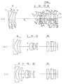
以下、本発明のズームレンズの実施例1〜3について説明する。実施例1〜3の無限遠物点合焦時の広角端(a)、中間状態(b)、望遠端(c)でのレンズ断面図をそれぞれ図1〜図3に示す。各図中、第1レンズ群はG1、絞りはS、第2レンズ群はG2、第3レンズ群はG3、第4レンズ群はG4、赤外カット吸収フィルターはIF、ローパスフィルターはLF、像面に配置される電子撮像素子であるCCDのカバーガラスはCG、CCDの像面はIで示してある。なお、赤外カット吸収フィルターIFに代えて、透明平板の入射面に近赤外シャープカットコートとしたものを用いてもよいし、ローパスフィルターLFに直接近赤外シャープカットコートを施してもよい。
【0076】
実施例1のズームレンズは、図1に示すように、物体側に凸の負メニスカスレンズと、物体側に凸の正メニスカスレンズとからなる負屈折力の第1レンズ群G1、開口絞りS、物体側に凸の正メニスカスレンズと物体側に凸の負メニスカスレンズの接合レンズと、両凸正レンズとからなる正屈折力の第2レンズ群G2、物体側に凸の負メニスカスレンズ1枚からなる負屈折力の第3レンズ群G3、像面側に凸の正メニスカスレンズ1枚からなる正屈折力の第4レンズ群G4からなり、広角端から望遠端に変倍する際は、第1レンズ群G1は像面側に移動し、第2レンズ群G2は開口絞りSと一体に物体側に移動し、第3レンズ群G3は第2レンズ群G2との間隔を一旦狭め再び広げながら物体側に移動し、第4レンズ群G4は固定されている。近距離の被写体にフォーカシングするために、第3レンズ群G3は像面側に移動される。
【0077】
非球面は、第1レンズ群G1の負メニスカスレンズの像面側の面、第2レンズ群G2の接合レンズの物体側の面、第4レンズ群G4の像面側の面の3面に用いられている。
【0078】
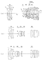
実施例2のズームレンズは、図2に示すように、物体側に凸の負メニスカスレンズと、物体側に凸の正メニスカスレンズとからなる負屈折力の第1レンズ群G1、開口絞りS、物体側に凸の正メニスカスレンズと物体側に凸の負メニスカスレンズの接合レンズと、両凸正レンズとからなる正屈折力の第2レンズ群G2、物体側に凸の負メニスカスレンズ1枚からなる負屈折力の第3レンズ群G3、像面側に凸の正メニスカスレンズ1枚からなる正屈折力の第4レンズ群G4からなり、広角端から望遠端に変倍する際は、第1レンズ群G1は中間状態までは像面側に移動し、中間状態から望遠端までは若干像面側に移動し、第2レンズ群G2は開口絞りSと一体に物体側に移動し、第3レンズ群G3は第2レンズ群G2との間隔を一旦狭め再び広げながら物体側に移動し、第4レンズ群G4は固定されている。近距離の被写体にフォーカシングするために、第3レンズ群G3は像面側に移動される。
【0079】
非球面は、第1レンズ群G1の負メニスカスレンズの像面側の面、第2レンズ群G2の接合レンズの物体側の面、第4レンズ群G4の像面側の面の3面に用いられている。
【0080】
実施例3のズームレンズは、図3に示すように、物体側に凸の負メニスカスレンズと、物体側に凸の正メニスカスレンズとからなる負屈折力の第1レンズ群G1、開口絞りS、物体側に凸の正メニスカスレンズと物体側に凸の負メニスカスレンズの接合レンズと、両凸正レンズとからなる正屈折力の第2レンズ群G2、物体側に凸の負メニスカスレンズ1枚からなる負屈折力の第3レンズ群G3、像面側に凸の正メニスカスレンズ1枚からなる正屈折力の第4レンズ群G4からなり、広角端から望遠端に変倍する際は、第1レンズ群G1は物体側に凹の軌跡を描いて移動し、望遠端では広角端より像面側の位置になり、第2レンズ群G2は開口絞りSと一体に物体側に移動し、第3レンズ群G3は第2レンズ群G2との間隔を一旦狭め再び広げながら物体側に移動し、第4レンズ群G4は固定されている。近距離の被写体にフォーカシングするために、第3レンズ群G3は像面側に移動される。
【0081】
非球面は、第1レンズ群G1の負メニスカスレンズの像面側の面、第2レンズ群G2の接合レンズの物体側の面、第4レンズ群G4の像面側の面の3面に用いられている。
【0082】
以下に、上記各実施例の数値データを示すが、記号は上記の外、fは全系焦点距離、ωは半画角、FNOはFナンバー、WEは広角端、STは中間状態、TEは望遠端、r1 、r2 …は各レンズ面の曲率半径、d1 、d2 …は各レンズ面間の間隔、nd1、nd2…は各レンズのd線の屈折率、νd1、νd2…は各レンズのアッベ数である。なお、非球面形状は、xを光の進行方向を正とした光軸とし、yを光軸と直交する方向にとると、下記の式にて表される。
【0083】
x=(y2 /r)/[1+{1−(K+1)(y/r)2 }1/2 ]+A4y4 +A6y6 +A8y8 + A10y10
ただし、rは近軸曲率半径、Kは円錐係数、A4、A6、A8、A10 はそれぞれ4次、6次、8次、10次の非球面係数である。
【0084】
以上の実施例1の無限遠物点合焦時及び被写体距離10cm合焦時の収差図をそれぞれ図4、図5に示す。これらの収差図において、(a)は広角端、(b)は中間状態、(c)は望遠端における球面収差SA、非点収差AS、歪曲収差DT、倍率色収差CCを示す。図中、“FIY”は像高を表す。
【0088】
次に、上記各実施例における条件(1)〜(18)の値、及び、Lの値を示す。
なお、実施例1〜3のローパスフィルターLFの総厚tLPF は何れも1.500(mm)で3枚重ねで構成している。もちろん、上述の実施例は、例えばローパスフィルターLFを1枚で構成する等、前記した構成の範囲内で種々変更可能である。
【0090】
ここで、有効撮像面の対角長Lと画素間隔aについて説明しておく。図6は、撮像素子の画素配列の1例を示す図であり、画素間隔aでR(赤)、G(緑)、B(青)の画素あるいはシアン、マゼンダ、イエロー、グリーン(緑)の4色の画素(図6)がモザイク状に配されている。有効撮像面は撮影した映像の再生(パソコン上での表示、プリンターによる印刷等)に用いる撮像素子上の光電変換面内における領域を意味する。図中に示す有効撮像面は、光学系の性能(光学系の性能が確保し得るイメージサークル)に合わせて、撮像素子の全光電変換面よりも狭い領域に設定されている。有効撮像面の対角長Lは、この有効撮像面の対角長である。なお、映像の再生に用いる撮像範囲を種々変更可能としてよいが、そのような機能を有する撮像装置に本発明のズームレンズを用いる際は、その有効撮像面の対角長Lが変化する。そのような場合は、本発明における有効撮像面の対角長Lは、Lのとり得る範囲における最大値とする。
【0091】
また、赤外カット手段については、赤外カット吸収フィルターIFと赤外シャープカットコートとがあり、赤外カット吸収フィルターIFはガラス中に赤外吸収体が含有される場合で、赤外シャープカットコートは吸収でなく反射によるカットである。したがって、前記したように、この赤外カット吸収フィルターIFを除去して、ローパスフィルターLFに直接赤外シャープカットコートを施してもよいし、ダミー透明平板上に施してもよい。
【0092】
この場合の近赤外シャープカットコートは、波長600nmでの透過率が80%以上、波長700nmでの透過率が10%以下となるように構成することが望ましい。具体的には、例えば次のような27層の層構成からなる多層膜である。ただし、設計波長は780nmである。
【0093】
基 板 材質 物理的膜厚(nm) λ/4
───────────────────────────────
第1層 Al2 O3 58.96 0.50
第2層 TiO2 84.19 1.00
第3層 SiO2 134.14 1.00
第4層 TiO2 84.19 1.00
第5層 SiO2 134.14 1.00
第6層 TiO2 84.19 1.00
第7層 SiO2 134.14 1.00
第8層 TiO2 84.19 1.00
第9層 SiO2 134.14 1.00
第10層 TiO2 84.19 1.00
第11層 SiO2 134.14 1.00
第12層 TiO2 84.19 1.00
第13層 SiO2 134.14 1.00
第14層 TiO2 84.19 1.00
第15層 SiO2 178.41 1.33
第16層 TiO2 101.03 1.21
第17層 SiO2 167.67 1.25
第18層 TiO2 96.82 1.15
第19層 SiO2 147.55 1.05
第20層 TiO2 84.19 1.00
第21層 SiO2 160.97 1.20
第22層 TiO2 84.19 1.00
第23層 SiO2 154.26 1.15
第24層 TiO2 95.13 1.13
第25層 SiO2 160.97 1.20
第26層 TiO2 99.34 1.18
第27層 SiO2 87.19 0.65
───────────────────────────────
空 気 。
【0094】
上記の近赤外シャープカットコートの透過率特性は図7に示す通りである。 また、ローパスフィルターLFの射出面側には、図8に示すような短波長域の色の透過を低滅する色フィルターを設けるか若しくはコーティングを行うことで、より一層電子画像の色再現性を高めている。
【0095】
具体的には、このフィルター若しくはコーティングにより、波長400nm〜700nmで透過率が最も高い波長の透過率に対する420nmの波長の透過率の比が15%以上であり、その最も高い波長の透過率に対する400nmの波長の透過率の比が6%以下であることが好ましい。
【0096】
それにより、人間の目の色に対する認識と、撮像及び再生される画像の色とのずれを低減させることができる。言い換えると、人間の視覚では認識され難い短波長側の色が、人間の目で容易に認識されることによる画像の劣化を防止することができる。
【0097】
上記の400nmの波長の透過率の比が6%を越えると、人間の目では認識され難い単波長城が認識し得る波長に再生されてしまい、逆に、上記の420nmの波長の透過率の比が15%よりも小さいと、人間の認識し得る波長城の再生が低くなり、色のバランスが悪くなる。
【0098】
このような波長を制限する手段は、補色モザイクフィルターを用いた撮像系においてより効果を奏するものである。
【0099】
上記各実施例では、図8に示すように、波長400nmにおける透過率を0%、420nmにおける透過率を90%、440nmにて透過率のピーク100%となるコーティングとしている。
【0100】
前記した近赤外シャープカットコートとの作用の掛け合わせにより、波長450nmの透過率99%をピークとして、400nmにおける透過率を0%、420nmにおける透過率を80%、600nmにおける透過率を82%、700nmにおける透過率を2%としている。それにより、より忠実な色再現を行っている。
【0101】
また、ローパスフィルターLFは、像面上投影時の方位角度が水平(=0°)と±45°方向にそれぞれ結晶軸を有する3種類のフィルターを光軸方向に重ねて使用しており、それぞれについて、水平にaμm、±45°方向にそれぞれSQRT(1/2) ×aだけずらすことで、モアレ抑制を行っている。ここで、SQRTは前記のようにスクエアルートであり平方根を意味する。
【0102】
また、CCDの撮像面I上には、図9に示す通り、シアン、マゼンダ、イエロー、グリーン(緑)の4色の色フィルターを撮像画素に対応してモザイク状に設けた補色モザイクフィルターを設けている。これら4種類の色フィルターは、それぞれが略同じ数になるように、かつ、隣り合う画素が同じ種類の色フィルターに対応しないようにモザイク状に配置されている。それにより、より忠実な色再現が可能となる。
【0103】
補色モザイクフィルターは、具体的には、図9に示すように少なくとも4種類の色フィルターから構成され、その4種類の色フィルターの特性は以下の通りであることが好ましい。
【0104】
グリーンの色フイルターGは波長GP に分光強度のピークを有し、
イエローの色フィルターYe は波長YP に分光強度のピークを有し、
シアンの色フィルターCは波長CP に分光強度のピークを有し、
マゼンダの色フィルターMは波長MP1とMP2にピークを有し、以下の条件を満足する。
【0105】
510nm<GP <540nm
5nm<YP −GP <35nm
−100nm<CP −GP <−5nm
430nm<MP1<480nm
580nm<MP2<640nm
さらに、グリーン、イエロー、シアンの色フィルターはそれぞれの分光強度のピークに対して波長530nmでは80%以上の強度を有し、マゼンダの色フィルターはその分光強度のピークに対して波長530nmでは10%から50%の強度を有することが、色再現性を高める上でより好ましい。
【0106】
上記各実施例におけるそれぞれの波長特性の一例を図10に示す。グリーンの色フィルターGは525nmに分光強度のビークを有している。イエローの色フィルターYe は555nmに分光強度のピークを有している。シアンの色フイルターCは510nmに分光強度のピークを有している。マゼンダの色フィルターMは445nmと620nmにピークを有している。また、530nmにおける各色フィルターは、それぞれの分光強度のピークに対して、Gは99%、Ye は95%、Cは97%、Mは38%としている。
【0107】
このような補色フイルターの場合、図示しないコントローラー(若しくは、デジタルカメラに用いられるコントローラー)で、電気的に次のような信号処理を行い、
輝度信号
Y=|G+M+Ye +C|×1/4
色信号
R−Y=|(M+Ye )−(G+C)|
B−Y=|(M+C)−(G+Ye )|
の信号処理を経てR(赤)、G(緑)、B(青)の信号に変換される。
【0108】
ところで、上記した近赤外シャープカットコートの配置位置は、光路上のどの位置であってもよい。また、ローパスフィルターLFの枚数も前記した通り2枚でも1枚でも構わない。
【0109】
さて、以上のような本発明の電子撮像装置は、ズームレンズで物体像を形成しその像をCCD等の電子撮像素子に受光させて撮影を行う撮影装置、とりわけデジタルカメラやビデオカメラ、情報処理装置の例であるパソコン、電話、特に持ち運びに便利な携帯電話等に用いることができる。以下に、その実施形態を例示する。
【0110】
図11〜図13は、本発明によるズームレンズをデジタルカメラの撮影光学系41に組み込んだ構成の概念図を示す。図11はデジタルカメラ40の外観を示す前方斜視図、図12は同後方斜視図、図13はデジタルカメラ40の構成を示す断面図である。デジタルカメラ40は、この例の場合、撮影用光路42を有する撮影光学系41、ファインダー用光路44を有するファインダー光学系43、シャッター45、フラッシュ46、液晶表示モニター47等を含み、カメラ40の上部に配置されたシャッター45を押圧すると、それに連動して撮影光学系41、例えば実施例1のズームレンズを通して撮影が行われる。撮影光学系41によって形成された物体像が、近赤外カットコートをダミー透明平板上に施してなる赤外カット吸収フィルターIF、光学的ローパスフィルターLFを介してCCD49の撮像面上に形成される。このCCD49で受光された物体像は、処理手段51を介し、電子画像としてカメラ背面に設けられた液晶表示モニター47に表示される。また、この処理手段51には記録手段52が接続され、撮影された電子画像を記録することもできる。なお、この記録手段52は処理手段51と別体に設けてもよいし、フロッピーディスクやメモリーカード、MO等により電子的に記録書込を行うように構成してもよい。また、CCD49に代わって銀塩フィルムを配置した銀塩カメラとして構成してもよい。
【0111】
さらに、ファインダー用光路44上にはファインダー用対物光学系53が配置してある。このファインダー用対物光学系53によって形成された物体像は、像正立部材であるポロプリズム55の視野枠57上に形成される。このポリプリズム55の後方には、正立正像にされた像を観察者眼球Eに導く接眼光学系59が配置されている。なお、撮影光学系41及びファインダー用対物光学系53の入射側、接眼光学系59の射出側にそれぞれカバー部材50が配置されている。
【0112】
このように構成されたデジタルカメラ40は、撮影光学系41が広画角で高変倍比であり、収差が良好で、明るく、フィルター等が配置できるバックフォーカスの大きなズームレンズであるので、高性能・低コスト化が実現できる。
【0113】
なお、図13の例では、カバー部材50として平行平面板を配置しているが、パワーを持ったレンズを用いてもよい。
【0114】
以上の本発明のズームレンズ及びそれを用いた電子撮像装置は例えば次のように構成することができる。
【0115】
〔1〕 物体側より順に、負の屈折力を有する第1レンズ群と、正の屈折力を有する第2レンズ群と、負の屈折力を有する第3レンズ群と、正の屈折力を有する第4レンズ群よりなり、
前記第2レンズ群と前記第3レンズ群との合成焦点距離は常に正であり、
無限遠物点合焦時における広角端から望遠端への変倍に際して、各レンズ群の間隔を変化させつつ、かつ、前記第2レンズ群及び前記第3レンズ群が物体側へのみ移動し、
前記第2レンズ群は、物体側から順に、非球面を有する正レンズL21、像側に凹面を向けたメニスカス形状の負レンズL22、正レンズL23の3枚のレンズよりなり、
前記第3レンズ群は1枚の負レンズよりなり、かつ、前記第3レンズ群はフォーカシング時に単独で移動し、
以下の条件を満足することを特徴とするズームレンズ。
【0116】
(1) 1.2<(R3F+R3R)/(R3F−R3R)<10
(2) 0.3<1/β3 <0.9
ただし、R3F、R3Rはそれぞれ第3レンズ群の物体側面及び像側面の光軸上の曲率半径、β3 は無限遠物点合焦時の広角端における第3レンズ群の倍率である。
【0117】
〔2〕 前記第4レンズ群は、変倍時及びフォーカシング時には固定され、かつ、何れかの面に非球面を有することを特徴とする上記1記載のズームレンズ。
【0118】
〔3〕 前記第4レンズ群は、以下の条件を満足する形状を持つ1つのレンズ成分からなることを特徴とする上記1又は2記載のズームレンズ。
【0119】
(5) 0.2<(R4F+R4R)/(R4F−R4R)<2.0
ただし、R4F、R4Rはそれぞれ第4レンズ群の物体側の面、像側の面の光軸上の曲率半径である。
【0120】
〔4〕 前記第4レンズ群は、1つの単レンズからなることを特徴とする上記3記載のズームレンズ。
【0121】
〔5〕 前記第2レンズ群が、以下の条件を満足することを特徴とする上記1から4の何れか1項記載のズームレンズ。
【0122】
(6) −1.0<(R23F +R23R )/(R23F −R23R )<0.5
(7) 0.04<t22/t2 <0.2
(8) ν22<26.5
ただし、R23F 、R23R はそれぞれ第2レンズ群の正レンズL23の物体側面及び像側面の光軸上の曲率半径、t22は第2レンズ群の正レンズL21の像側面から負レンズL22の像側面までの光軸上の距離、t2 は第2レンズ群の最も物体側のレンズ面から最も像側のレンズ面までの光軸上の厚み、ν22は第2レンズ群の負レンズL22の媒質のd線基準のアッベ数である。
【0123】
〔6〕 前記第1レンズ群は、非球面を含む負レンズと、正レンズの2枚のレンズで構成され、以下の条件を満足することを特徴とする上記1から5の何れか1項記載のズームレンズ。
【0124】
(12) 20<ν11−ν12
(13) −10<(R12F +R12R )/(R12F −R12R )<−2
ただし、ν11は第1レンズ群の負レンズのd線基準のアッベ数、ν12は第1レンズ群の正レンズのd線基準のアッベ数、R12F 、R12R はそれぞれ第1レンズ群の正レンズの物体側面及び像側面の光軸上の曲率半径である。
【0125】
〔7〕 前記第1レンズ群と第2レンズ群との間に絞りを配したことを特徴とする上記1から6の何れか1項記載のズームレンズ。
【0126】
〔8〕 変倍時に前記絞りが第2レンズ群と一体で移動することを特徴とする上記7記載のズームレンズ。
【0127】
〔9〕 前記第2レンズ群における正レンズL21と負レンズL22とは接合されていることを特徴とする上記1から8の何れか1項記載のズームレンズ。
【0128】
〔10〕 上記1から9の何れか1項記載のズームレンズを備え、かつ、その像側に撮像素子を配したことを特徴とする電子撮像装置。
【0129】
〔11〕 上記9記載のズームレンズ及びその像側に配された撮像素子を有し、かつ、前記ズームレンズの第2レンズ群が以下の条件を満足することを特徴とする電子撮像装置。
【0130】
(9) 0.6<R22R /R21F <1.2
(10) 0.0<L/R22F <0.8
ただし、R21F 、R22F 、R22R はそれぞれ第2レンズ群の正レンズL21の物体側面、負レンズL22の物体側の接合面、負レンズL22の像側面における光軸上の曲率半径、Lは撮像素子の有効撮像領域の対角長である。
【0131】
〔12〕 前記ズームレンズの第3レンズ群が以下の条件を満足することを特徴とする上記10又は11記載の電子撮像装置。
【0132】
(3) ν3 >30
(4) 0.2<−L/f3 <0.6
ただし、ν3 は第3レンズ群を構成する負レンズのd線基準のアッベ数、f3 は第3レンズ群の合成焦点距離、Lは撮像素子の有効撮像領域の対角長である。
【0133】
〔13〕 前記ズームレンズの第1レンズ群が、物体側から順に、屈折面に非球面を有する負レンズ、像側面よりも物体側面の方が強い曲率を有する正レンズの2枚のレンズにて構成され、以下の条件を満足することを特徴とする上記10から12の何れか1項記載の電子撮像装置。
【0134】
(11) 0.6<R11R /L<1.3
ただし、R11R は第1 レンズ群の負レンズの像側面における光軸上の曲率半径、Lは撮像素子の有効撮像領域の対角長である。
【0135】
〔14〕 前記撮像素子の有効撮像領域の対角長Lが以下の条件を満足することを特徴とする上記10から13の何れか1項記載の電子撮像装置。
【0136】
3.0mm<L<12.0mm
【0137】
【発明の効果】
本発明により、沈胴厚が薄く収納性に優れ、かつ、高倍率でリアフォーカスにおいても結像性能の優れたズームレンズを得ることができ、ビデオカメラやデジタルカメラの徹底的薄型化を図ることが可能となる。
【図面の簡単な説明】
【図1】本発明の電子撮像装置に用いられるズームレンズの実施例1の無限遠物点合焦時の広角端(a)、中間状態(b)、望遠端(c)でのレンズ断面図である。
【図2】実施例2のズームレンズの図1と同様のレンズ断面図である。
【図3】実施例3のズームレンズの図1と同様のレンズ断面図である。
【図4】実施例1の無限遠物点合焦時の収差図である。
【図5】実施例1の被写体距離10cm合焦時の収差図である。
【図6】電子撮像素子にて撮影を行う場合の有効撮像面の対角長について説明するための図である。
【図7】近赤外シャープカットコートの一例の透過率特性を示す図である。
【図8】ローパスフィルターの射出面側に設ける色フィルターの一例の透過率特性を示す図である。
【図9】補色モザイクフィルターの色フィルター配置を示す図である。
【図10】補色モザイクフィルターの波長特性の一例を示す図である。
【図11】本発明によるズームレンズを組み込んだデジタルカメラの外観を示す前方斜視図である。
【図12】図11のデジタルカメラの後方斜視図である。
【図13】図11のデジタルカメラの断面図である。
【符号の説明】
G1…第1レンズ群
G2…第2レンズ群
G3…第3レンズ群
G4…第4レンズ群
S…開口絞り
IF…赤外カット吸収フィルター
LF…ローパスフィルター
CG…カバーガラス
I…像面
E…観察者眼球
40…デジタルカメラ
41…撮影光学系
42…撮影用光路
43…ファインダー光学系
44…ファインダー用光路
45…シャッター
46…フラッシュ
47…液晶表示モニター
49…CCD
50…カバー部材
51…処理手段
52…記録手段
53…ファインダー用対物光学系
55…ポロプリズム
57…視野枠
59…接眼光学系[0001]
BACKGROUND OF THE INVENTION
The present invention relates to a zoom lens and an electronic imaging device using the zoom lens, and more particularly, to a zoom lens that has been thinned in the depth direction by devising an optical system part such as a zoom lens, and a video camera or a digital camera using the zoom lens. The present invention relates to an electronic imaging device. In addition, the zoom lens relates to a lens that enables rear focus.
[0002]
[Prior art]
In recent years, digital cameras (electronic cameras) have attracted attention as next-generation cameras that replace silver salt 35 mm film (commonly known as Leica version) cameras. Furthermore, it has come to have a number of categories in a wide range from a high-function type for business use to a portable popular type.
[0003]
In the present invention, focusing on the category of portable popular type, it is aimed to provide a technology for realizing a video camera and a digital camera with a small depth while ensuring a high image quality. The biggest bottleneck in reducing the depth direction of the camera is the thickness from the most object-side surface to the imaging surface of the optical system, particularly the zoom lens system. Recently, it has become the mainstream to adopt a so-called collapsible lens barrel that protrudes the optical system from the camera body during shooting and stores the optical system in the camera body when carried.
[0004]
However, the thickness when the optical system is retracted varies greatly depending on the lens type and filter used. In particular, in order to set the specifications such as the zoom ratio and F value high, the so-called positive leading zoom lens in which the lens unit closest to the object side has positive refractive power has a large thickness and dead space of each lens element, Even if the lens barrel is retracted, the thickness is not reduced (Japanese Patent Laid-Open No. 11-258507). The negative leading type, especially the zoom lens having 2 to 3 groups, is advantageous in this respect, but it is retracted even when the number of elements in the group is large, the thickness of the element is large, or the most object side lens is a positive lens. However, it does not become thin (Japanese Patent Laid-Open No. 11-52246). As an example of what is currently known and suitable for an electronic image pickup device, has good imaging performance including a zoom ratio, an angle of view, an F value, and the like, and has the possibility of making the collapsible thickness the thinnest, Japanese Patent Laid-Open No. Hei 11- No. 194274, JP-A-11-287953, JP-A-2000-9997, and the like.
[0005]
In order to obtain a camera body with a small depth, first, the total number of lenses must be reduced, and the combined magnification of all the lens units in the second and subsequent groups should be increased to reduce the entrance pupil position on the wide-angle side, thereby reducing the first group. In addition, the lens movement at the time of focusing is not the front group, but the so-called rear focus method is used, and an optical system with little aberration fluctuation at the time of focusing is selected. There is also a method of reducing the size of the image sensor, but in order to obtain the same number of pixels, it is necessary to reduce the pixel pitch, and the lack of sensitivity must be covered by the optical system. The same is true for diffraction. For that purpose, the F value must be brightened.
[0006]
[Problems to be solved by the invention]
The present invention has been made in view of such a situation in the prior art, and its object is to have a small number of components, a small and simple mechanism layout such as a rear focus method, and a stable and high connection from infinity to a short distance. Select a zoom system or zoom configuration that has image performance, and further reduce the total thickness of each group by thinning the lens elements, or considering the selection of filters, so that the lens system can be completely stored. The aim is to reduce the thickness in the depth direction.
[0007]
[Means for Solving the Problems]
In order to achieve the above object, the zoom lens of the present invention has, in order from the object side, a first lens group having a negative refractive power, a second lens group having a positive refractive power, and a negative refractive power. A third lens group and a fourth lens group having positive refractive power;
The combined focal length of the second lens group and the third lens group is always positive,
At the time of zooming from the wide-angle end to the telephoto end at the time of focusing on an object point at infinity, the second lens group and the third lens group move only to the object side while changing the distance between the lens groups,
The second lens group, in order from the object side, includes a positive lens L21 having an aspherical surface, a meniscus negative lens L22 having a concave surface facing the image side, and a positive lens L23.
The third lens group is composed of one negative lens, and the third lens group moves independently during focusing,
The following conditions are satisfied.
[0008]
(1) 1.2 <(R 3F + R 3R ) / (R 3F −R 3R ) <10
(2) 0.3 <1 / β 3 <0.9
Here, R 3F and R 3R are the curvature radii on the optical axis of the object side surface and the image side surface of the third lens group, respectively, and β 3 is the magnification of the third lens group at the wide-angle end when focusing on an object point at infinity.
[0009]
Hereinafter, the reason and effect | action which take the said structure in this invention are demonstrated.
[0010]
The zoom lens of the present invention includes, in order from the object side, a first lens group having a negative refractive power, a second lens group having a positive refractive power, a third lens group having a negative refractive power, and a positive lens It comprises a fourth lens group having refractive power, and the combined focal length of the second lens group and the third lens group is always positive, and zooming from the wide-angle end to the telephoto end when focusing on an object point at infinity. At this time, the second lens group and the third lens group move only to the object side while changing the interval between the lens groups, and the second lens group has a positive aspherical surface in order from the object side. The lens L21 includes three lenses, a meniscus negative lens L22 having a concave surface facing the image side, and a positive lens L23. The third lens group includes one negative lens, and the third lens group includes The so-called rear that moves independently during focusing Okasu is a type zoom lens.
[0011]
In the present invention, the term “lens” refers to a lens made of a single medium as a unit, and the cemented lens consists of a plurality of lenses. Moreover, a lens component means the lens group which does not arrange | position an air space | interval between them, and means a single lens or a cemented lens.
[0012]
In the above case, the following conditions must be satisfied.
[0013]
(1) 1.2 <(R 3F + R 3R ) / (R 3F −R 3R ) <10
(2) 0.3 <1 / β 3 <0.9
Here, R 3F and R 3R are the curvature radii on the optical axis of the object side surface and the image side surface of the third lens group, respectively, and β 3 is the magnification of the third lens group at the wide-angle end when focusing on an object point at infinity.
[0014]
Condition (1) is an indispensable condition for suppressing aberration fluctuations during focusing. In addition, in the lens system of the present invention, when the lens is housed in the camera body, at least the variable distance at the time of zooming or focusing is reduced until just before mechanical interference occurs, so that the camera body is extremely thin, so that it is as dead as possible. The generation of space must be suppressed. If the upper limit of 10 is exceeded, the shape of the negative lens of the third lens group itself tends to be bulky, which is not preferable. If the lower limit of 1.2 is exceeded, spherical aberration is significantly generated by focusing, which is not preferable.
[0015]
Condition (2) indicates the establishment of focus by the third lens group. If the upper limit of 0.9 and the lower limit of 0.3 are exceeded, the focus position is moved satisfactorily even if the third lens group is moved. I can't.
[0016]
Note that it is better to set one or both of the conditions (1) and (2) as follows.
[0017]
(1) ′ 1.6 <(R 3F + R 3R ) / (R 3F −R 3R ) <8.0
(2) '0.35 <1 / β 3 <0.85
Furthermore, it is better to set one or both of the conditions (1) and (2) as follows. In particular, it is best to do both as follows.
[0018]
(1) "2.0 <(R 3F + R 3R ) / (R 3F -R 3R ) <6.0
(2) "0.4 <1 / β 3 <0.8
Further, it is more preferable that the following conditions are satisfied.
[0019]
(3) ν 3 > 30
(4) 0.2 <−L / f 3 <0.6
Here, ν 3 is the Abbe number based on the d-line of the negative lens constituting the third lens group, f 3 is the combined focal length of the third lens group, and L is the diagonal length of the effective imaging region of the image sensor.
[0020]
Condition (3) defines the Abbe number of the negative lens in the third lens group. It is desirable that the dispersion be as low as possible so that chromatic aberration does not change during focusing. When the lower limit of 30 is exceeded, the balance between axial chromatic aberration and lateral chromatic aberration is lost. If an upper limit value is added, the upper limit value should be 85 and ν 3 should be less than that. If the upper limit value 85 is exceeded, the glass material becomes expensive.
[0021]
Condition (4) defines the power of the third lens group, and if the upper limit of 0.6 is exceeded, the exit pupil position is close to the image plane, especially at the wide-angle end, and shading tends to occur, which is not preferable.
[0022]
In addition, it is better to set one or both of the conditions (3) and (4) as follows.
[0023]
(3) 'ν 3 > 32
(4) ′ 0.25 <−L / f 3 <0.5
Furthermore, it is better to set one or both of the conditions (3) and (4) as follows. In particular, it is best to do both as follows.
[0024]
(3) ν 3 > 34
(4) "0.3 <-L / f 3 <0.4
Note that this rear focus method is particularly suitable for zoom lenses having a positive refractive power lens group that moves monotonically toward the object side when zooming from the wide-angle end to the telephoto end. There is a tendency for aberration fluctuations in the entire double range and residual aberrations after correcting them to be small, especially astigmatism and coma. In order to correct this, it is effective to perform correction by introducing an aspherical surface into the final group. When this group is moved for focusing, aberration fluctuations are large, and even when moved during zooming, no particular effect is obtained. Therefore, it is desirable to fix in the optical axis direction during zooming and focusing. A single lens component is sufficient for the configuration. In addition, aberration correction is advantageous when the following conditions are satisfied with respect to the shape.
[0025]
(5) 0.2 <(R 4F + R 4R ) / (R 4F −R 4R ) <2.0
Here, R 4F and R 4R are the radii of curvature on the optical axis of the object side surface and the image side surface of the fourth lens group, respectively.
[0026]
If the upper limit of 2.0 of the condition (5) is exceeded, spherical aberration correction, and if the lower limit of 0.2 is exceeded, it is difficult to correct off-axis aberrations such as astigmatism.
[0027]
It is better to do the following.
[0028]
(5) ′ 0.4 <(R 4F + R 4R ) / (R 4F −R 4R ) <1.7
Furthermore, it is best to do the following.
[0029]
(5) ”0.6 <(R 4F + R 4R ) / (R 4F −R 4R ) <1.4
Next, regarding the second lens group, the following conditions may be satisfied.
[0030]
(6) −1.0 <(R 23F + R 23R ) / (R 23F −R 23R ) <0.5
(7) 0.04 <t 22 / t 2 <0.2
(8) ν 22 <26.5
Here, R 23F and R 23R are the curvature radii on the optical axis of the object side surface and the image side surface of the positive lens L23 of the second lens group, respectively, and t 22 is from the image side surface of the positive lens L21 of the second lens group to the negative lens L22. The distance on the optical axis to the image side surface, t 2 is the thickness on the optical axis from the lens surface closest to the object side to the lens surface closest to the image side, and ν 22 is the negative lens L22 of the second lens group. Is the Abbe number based on the d-line of the medium.
[0031]
Condition (6) is a rule regarding the shape factor of the positive lens L23 of the second lens group. If the lower limit of −1.0 is exceeded, the air gap d 22 in the second lens group can be easily reduced, but it becomes difficult to correct coma and astigmatism. If the upper limit of 0.5 is exceeded, d 22 tends to increase due to mechanical interference between the negative lens L22 and the positive lens L23 of the second lens group, and the lens system in the retracted lens system, that is, the lens system when retracted It becomes a footpad to reduce the depth thickness.
[0032]
Condition (7) defines a distance t 22 on the optical axis from the image side surface of the positive lens L21 of the second lens group to the image side surface of the negative lens L22. The astigmatism cannot be corrected unless this part is thickened to some extent, but this is a problem for the purpose of reducing the thickness of each element of the optical system. Therefore, astigmatism is corrected by introducing an aspherical surface on either surface of the first lens group or the fourth lens group. If the lower limit of 0.04 is still exceeded, astigmatism cannot be corrected completely. If the upper limit of 0.2 is exceeded, the thickness is unacceptable.
[0033]
Condition (8) is a rule regarding correction of axial chromatic aberration of magnification, and if the upper limit of 26.5 is exceeded, insufficient correction of axial chromatic aberration will result. The lower limit is not particularly set because there is no medium suitable for reality below. However, if a lower limit value is added, the lower limit value should be set to 20 and ν 22 should be higher than that. When the
[0034]
In addition, it is better to set one or more or all of the conditions (6) to (8) as follows.
[0035]
(6) ′ − 0.9 <(R 23F + R 23R ) / (R 23F −R 23R ) <0.4
(7) ′ 0.06 <t 22 / t 2 <0.18
(8) 'ν 22 <26
Furthermore, it is better to set one or more of the conditions (6) to (8) as follows. In particular, it is best to do everything as follows.
[0036]
(6) "-0.8 <( R23F + R23R ) / ( R23F- R23R ) <0.3
(7) "0.08 <t 22 / t 2 <0.16
(8) ν 22 <25.5
Further, regarding the second lens group, it is preferable that the positive lens L21 and the negative lens L22 are cemented and the following conditions are satisfied.
[0037]
(9) 0.6 <R 22R / R 21F <1.2
(10) 0.0 <L / R 22F <0.8
Where R 21F , R 22F and R 22R are the radius of curvature on the optical axis on the object side surface of the positive lens L21, the cemented surface on the object side of the negative lens L22, and the image side surface of the negative lens L22 in the second lens group, respectively. It is the diagonal length of the effective imaging area of an image sensor.
[0038]
If the upper limit of 1.2 of the condition (9) is exceeded, it is advantageous for correcting spherical aberration, coma aberration, and astigmatism of the entire system aberration, but the effect of reducing the decentration sensitivity by joining is small. If the lower limit of 0.6 is exceeded, it will be difficult to correct spherical aberration, coma aberration, and astigmatism of the total system aberration.
[0039]
Condition (10) is also a rule regarding correction of axial chromatic aberration of magnification. If the upper limit of 0.8 is exceeded, the thickness of the cemented lens of the second lens group can be easily reduced, but correction of axial chromatic aberration becomes difficult. Become. If the lower limit of 0.0 is exceeded, it is advantageous for correcting axial chromatic aberration, but it is necessary to increase the thickness of the cemented lens, and it becomes a foothold to reduce the collapsed thickness.
[0040]
In addition, it is better to set one or both of the conditions (9) and (10) as follows.
[0041]
(9) ′ 0.7 <R 22R / R 21F <1.1
(10) '0.05 <L / R 22F <0.7
Furthermore, it is better to set one or both of the conditions (9) and (10) as follows. In particular, it is best to do both as follows.
[0042]
(9) ”0.8 <R 22R / R 21F <1.0
(10) "0.1 <L / R 22F <0.6
Finally, there are conditions for thinning the first lens group. The first lens group satisfies the following conditions, and if it is composed of only a negative lens including an aspherical surface and a positive lens, the chromatic aberration and each Seidel off-axis aberration can be corrected satisfactorily. To contribute.
[0043]
(11) 0.6 <R 11R /L<1.3
Here, R 11R is the radius of curvature on the optical axis on the image side surface of the negative lens of the first lens group, and L is the diagonal length of the effective imaging region of the imaging device. In the case of an aspherical surface, the radius of curvature on the optical axis is used.
[0044]
If the lower limit of 0.6 in the condition (11) is exceeded, it is difficult to correct distortion and coma even if an aspherical surface is introduced. If the upper limit of 1.3 is exceeded, it is difficult to correct lateral chromatic aberration. Become.
[0045]
It is better to do the following.
[0046]
(11) '0.65 <R 11R /L<1.2
Furthermore, it is best to do the following.
[0047]
(11) ”0.7 <R 11R /L<1.1
In addition, the following conditions should be satisfied. .
[0048]
(12) 20 <ν 11 −ν 12
(13) -10 <( R12F + R12R ) / ( R12F- R12R ) < -2
Where ν 11 is the Abbe number based on the d-line of the negative lens of the first lens group, ν 12 is the Abbe number based on the d-line of the positive lens of the first lens group, and R 12F and R 12R are respectively the first lens group. It is a radius of curvature on the optical axis of the object side surface and the image side surface of the positive lens.
[0049]
The condition (12) is defined with respect to the variation of the on-axis and lateral chromatic aberration at the time of zooming. If the lower limit of 20 is exceeded, it will be on the axis. Variation in chromatic aberration of magnification tends to increase. The upper limit is not particularly set because there is no medium more suitable for reality, but if an upper limit value is added, the upper limit value is set to 75, and ν 11 −ν 12 should be less than that. If the upper limit 75 is exceeded, the glass material becomes expensive.
[0050]
Condition (13) defines the shape factor of the positive lens in the first lens group. Exceeding the lower limit of −10 is disadvantageous in correcting astigmatism, and also disadvantageous in that it requires an extra space with the second lens group in order to avoid mechanical interference during zooming. If the upper limit of −2 is exceeded, correction of distortion aberration tends to be disadvantageous.
[0051]
In addition, it is better to set one or both of the conditions (12) and (13) as follows.
[0052]
(12) '22 <ν 11 −ν 12
(13) '-9 <( R12F + R12R ) / ( R12F- R12R ) <-2.5
Furthermore, it is better to set one or both of the conditions (12) and (13) as follows. In particular, it is best to do both as follows.
[0053]
(12) ”24 <ν 11 −ν 12
(13) "-8 <( R12F + R12R ) / ( R12F- R12R ) <-3
Note that the zoom lens of the present invention is advantageous in constructing an electronic imaging device including a wide angle region. In particular, it is preferably used for an electronic imaging apparatus in which the half angle of view ω W in the diagonal direction at the wide angle end satisfies the following conditions (the wide angle end half angle of view described in each example described later corresponds to ω W. ).
[0054]
27 ° <ω W <42 °
If the wide angle end half angle of view becomes narrower beyond the lower limit of 27 ° under this condition, it becomes advantageous for aberration correction, but it is not a practical angle of view at the wide angle end. On the other hand, when the upper limit of 42 ° is exceeded, distortion and chromatic aberration of magnification tend to occur, and the number of lenses increases.
[0055]
In addition, since the zoom lens used in the electronic image sensor of the present invention can guide the off-axis principal ray to the image sensor in a nearly vertical state, a good image can be obtained up to the periphery of the image. At that time, it is more preferable that the diagonal length L of the effective imaging region of the imaging device is 3.0 mm to 12.0 mm in order to achieve both good image quality and downsizing.
[0056]
As described above, a means for improving the imaging performance while reducing the retractable thickness of the zoom lens unit has been provided.
[0057]
Next, mention is made of thinning filters. In an electronic imaging apparatus, an infrared absorption filter having a certain thickness is usually inserted closer to the object side than the imaging element so that infrared light does not enter the imaging surface. Consider replacing this with a thin coating. Naturally, it will be thinner, but it has a side effect. A near-infrared sharp cut coat with a transmittance (τ 600 ) at a wavelength of 600 nm of 80% or more and a transmittance (τ 700 ) at 700 nm of 8% or less on the object side of the image sensor behind the zoom lens system When introduced, the transmittance in the near infrared region of 700 nm or more is lower than that of the absorption type, and the transmittance on the red side is relatively high, which is a disadvantage of a solid-state imaging device such as a CCD having a complementary color mosaic filter. The magenta tendency on the side is alleviated by gain adjustment, and color reproduction similar to that of a solid-state imaging device such as a CCD having a primary color filter can be obtained.
[0058]
That is,
(14) τ 600 / τ 550 ≧ 0.8
(15) τ 700 / τ 550 ≦ 0.08
It is desirable to satisfy. However, (tau) 550 is the transmittance | permeability in wavelength 550nm.
[0059]
Note that it is better to set one or both of the conditions (14) and (15) as follows.
[0060]
(14) 'τ 600 / τ 550 ≧ 0.85
(15) 'τ 700 / τ 550 ≦ 0.05
Furthermore, it is better to set one or both of the conditions (14) and (15) as follows. In particular, it is best to do both as follows.
[0061]
(14) ”τ 600 / τ 550 ≧ 0.9
(15) ”τ 700 / τ 550 ≦ 0.03
Another drawback of a solid-state imaging device such as a CCD is that the sensitivity to the near-ultraviolet wavelength of 550 nm is considerably higher than that of the human eye. This also highlights the color blur at the edge of the image due to chromatic aberration in the near ultraviolet region. In particular, it is fatal to downsize the optical system. Therefore, the ratio of transmittance (τ 400 ) at a wavelength of 400 nm to that at 550 nm (τ 550 ) is less than 0.08, and the ratio of the transmittance at 440 nm (τ 440 ) to that at 550 nm (τ 550 ). Inserting an absorber or reflector that exceeds 0.4 on the optical path does not lose the wavelength range necessary for color reproduction (while maintaining good color reproduction), and significantly reduces noise such as color bleeding. Is done.
[0062]
That is,
(16) τ 400 / τ 550 ≦ 0.08
(17) τ 440 / τ 550 ≧ 0.4
It is desirable to satisfy.
[0063]
In addition, it is better to set one or both of the conditions (16) and (17) as follows.
[0064]
(16) 'τ 400 / τ 550 ≦ 0.06
(17) 'τ 440 / τ 550 ≧ 0.5
Furthermore, it is better to set one or both of the conditions (16) and (17) as follows. In particular, it is best to do both as follows.
[0065]
(16) ”τ 400 / τ 550 ≦ 0.04
(17) ”τ 440 / τ 550 ≧ 0.6
These filters are preferably installed between the imaging optical system and the image sensor.
[0066]
On the other hand, in the case of a complementary color filter, because of its high transmitted light energy, it has substantially higher sensitivity than a CCD with a primary color filter and is advantageous in terms of resolution. It is. For the optical low-pass filter as the other filter, the total thickness t LPF (mm) should satisfy the following condition.
[0067]
(18) 0.15 <t LPF /a<0.45
However, a is a horizontal pixel pitch (unit: μm) of the image sensor, and is 5 μm or less.
[0068]
In order to reduce the collapsed thickness, it is effective to make the optical low-pass filter thinner, but in general, the moire suppressing effect is reduced, which is not preferable. On the other hand, as the pixel pitch decreases, the contrast of frequency components above the Nyquist limit decreases due to the influence of diffraction of the imaging lens system, and the phenomenon of the moire suppression effect is allowed to some extent. For example, when three types of filters having crystal axes in the horizontal (= 0 °) and ± 45 ° directions are projected in the direction of the optical axis when projected on the image plane, the effect of suppressing moiré is considerably improved. It has been known. As a specification in which the filter is the thinnest in this case, it is known that the filter is shifted by SQRT (1/2) * a μm horizontally by aμm and ± 45 °. The filter thickness at this time is approximately [1 + 2 * SQRT (1/2)] * a / 5.88 (mm). Here, SQRT is a square route and means a square root. This is a specification in which the contrast is zero at a frequency corresponding to the Nyquist limit. If it is made thinner by several percent to several tens of percent than this, a little frequency contrast corresponding to the Nyquist limit appears, but it can be suppressed by the influence of the diffraction.
[0069]
It is preferable to satisfy the condition (18) including filter specifications other than those described above, for example, when two sheets are stacked or one sheet is used. If the upper limit of 0.45 is exceeded, the optical low-pass filter is too thick and hinders thinning. When the lower limit of 0.15 is exceeded, moire removal becomes insufficient. However, the condition of a in carrying out this is 5 μm or less.
[0070]
If a is 4 μm or less, it is more susceptible to diffraction (18) ′ 0.13 <t LPF /a<0.42.
It is good.
[0071]
Further, the following may be performed according to the number of low-pass filters superimposed on the horizontal pixel pitch.
[0072]
When an electronic image sensor with a small pixel pitch is used, the image quality deteriorates due to the diffraction effect due to narrowing down. Therefore, there are a plurality of apertures having a fixed aperture size, and one of them is any one of the optical paths between the lens surface closest to the image side of the first lens group and the lens surface closest to the object side of the third lens group. An electronic imaging device that can be inserted into and can be exchanged with other apertures to adjust the illuminance of the image plane. Among the plurality of apertures, some of the apertures have transmittance for 550 nm. It is preferable to adjust the amount of light so as to have media that are different and less than 80%. Alternatively, when adjustment is performed so that the amount of light corresponds to an F value such that a (μm) / F number <0.4, the medium having different transmittances for 550 nm and less than 80% in the opening. An electronic imaging device having For example, if the medium is not within the above range from the open value, or a dummy medium with a transmittance of 550 nm or more is set to 91% or more, and the aperture diameter is within the range, the aperture stop diameter is reduced to such an extent that the influence of diffraction occurs. It is better to adjust the amount of light with something like an ND filter.
[0074]
Alternatively, the plurality of openings may be arranged such that their diameters are reduced in inverse proportion to the F value, and optical low-pass filters having different frequency characteristics may be placed in the openings instead of the ND filters. Since diffraction degradation increases as the aperture is narrowed down, the frequency characteristic of the optical low-pass filter is set higher as the aperture diameter decreases.
[0075]
DETAILED DESCRIPTION OF THE INVENTION
Examples 1 to 3 of the zoom lens according to the present invention will be described below. FIGS. 1 to 3 show sectional views of lenses at the wide-angle end (a), the intermediate state (b), and the telephoto end (c) when focusing on an object point at infinity according to the first to third embodiments. In each figure, the first lens group is G1, the diaphragm is S, the second lens group is G2, the third lens group is G3, the fourth lens group is G4, the infrared cut absorption filter is IF, the low-pass filter is LF, the image The cover glass of the CCD, which is an electronic image pickup device arranged on the surface, is indicated by CG, and the image surface of the CCD is indicated by I. Instead of the infrared cut absorption filter IF, a transparent flat plate incident surface with a near infrared sharp cut coat may be used, or the low pass filter LF may be directly provided with a near infrared sharp cut coat. .
[0076]
As shown in FIG. 1, the zoom lens of Example 1 includes a first lens group G1 having a negative refractive power composed of a negative meniscus lens convex on the object side and a positive meniscus lens convex on the object side, an aperture stop S, A second lens group G2 having a positive refractive power composed of a cemented lens of a positive meniscus lens convex on the object side and a negative meniscus lens convex on the object side, and a biconvex positive lens, and a single negative meniscus lens convex on the object side A third lens group G3 having a negative refractive power and a fourth lens group G4 having a positive refractive power made up of one positive meniscus lens convex on the image plane side. When zooming from the wide angle end to the telephoto end, The lens group G1 moves to the image plane side, the second lens group G2 moves to the object side integrally with the aperture stop S, and the third lens group G3 temporarily narrows the distance from the second lens group G2 and widens it again. The fourth lens group G4 is fixed. In order to focus on a subject at a short distance, the third lens group G3 is moved to the image plane side.
[0077]
The aspherical surfaces are used for the three surfaces of the negative meniscus lens image surface side of the first lens group G1, the object side surface of the cemented lens of the second lens group G2, and the image surface side surface of the fourth lens group G4. It has been.
[0078]
As shown in FIG. 2, the zoom lens according to the second embodiment includes a first lens group G1 having a negative refractive power including a negative meniscus lens convex on the object side and a positive meniscus lens convex on the object side, an aperture stop S, A second lens group G2 having a positive refractive power composed of a cemented lens of a positive meniscus lens convex on the object side and a negative meniscus lens convex on the object side, and a biconvex positive lens, and a single negative meniscus lens convex on the object side A third lens group G3 having a negative refractive power and a fourth lens group G4 having a positive refractive power made up of one positive meniscus lens convex on the image plane side. When zooming from the wide angle end to the telephoto end, The lens group G1 moves to the image plane side to the intermediate state, moves slightly to the image plane side from the intermediate state to the telephoto end, the second lens group G2 moves to the object side integrally with the aperture stop S, and The lens group G3 once again narrows the distance between the second lens group G2 and again. Lower while moving toward the object side, the fourth lens group G4 are fixed. In order to focus on a subject at a short distance, the third lens group G3 is moved to the image plane side.
[0079]
The aspherical surfaces are used for the three surfaces of the negative meniscus lens image surface side of the first lens group G1, the object side surface of the cemented lens of the second lens group G2, and the image surface side surface of the fourth lens group G4. It has been.
[0080]
As shown in FIG. 3, the zoom lens of Embodiment 3 includes a first lens group G1 having a negative refractive power composed of a negative meniscus lens convex on the object side and a positive meniscus lens convex on the object side, an aperture stop S, A second lens group G2 having a positive refractive power composed of a cemented lens of a positive meniscus lens convex on the object side and a negative meniscus lens convex on the object side, and a biconvex positive lens, and a single negative meniscus lens convex on the object side A third lens group G3 having a negative refractive power and a fourth lens group G4 having a positive refractive power made up of one positive meniscus lens convex on the image plane side. When zooming from the wide angle end to the telephoto end, The lens group G1 moves along a concave locus on the object side, and at the telephoto end is positioned closer to the image plane side than the wide-angle end. The second lens group G2 moves toward the object side integrally with the aperture stop S, and The lens group G3 is once again narrowed and widened with respect to the second lens group G2. While moving toward the object side, the fourth lens group G4 are fixed. In order to focus on a subject at a short distance, the third lens group G3 is moved to the image plane side.
[0081]
The aspherical surfaces are used for the three surfaces of the negative meniscus lens image surface side of the first lens group G1, the object side surface of the cemented lens of the second lens group G2, and the image surface side surface of the fourth lens group G4. It has been.
[0082]
The numerical data of each of the above embodiments are shown below. Symbols are the above, f is the total focal length, ω is the half field angle, FNO is the F number, WE is the wide angle end, ST is the intermediate state, TE telephoto end, r 1, r 2 ... curvature radius of each lens surface, d 1, d 2 ... the spacing between the lens surfaces, n d1, n d2 ... d-line refractive index of each lens, [nu d1 , Ν d2 ... Is the Abbe number of each lens. The aspherical shape is represented by the following formula, where x is an optical axis with the light traveling direction being positive, and y is a direction orthogonal to the optical axis.
[0083]
x = (y 2 / r) / [1+ {1- (K + 1) (y / r) 2} 1/2] + A 4 y 4 + A 6 y 6 + A 8
Here, r is a paraxial radius of curvature, K is a conical coefficient, and A 4 , A 6 , A 8 , and A 10 are fourth-order, sixth-order, eighth-order, and tenth-order aspherical coefficients, respectively.
[0084]
FIG. 4 and FIG. 5 show aberration diagrams of Example 1 when focusing on an object point at infinity and focusing on a subject distance of 10 cm, respectively. In these aberration diagrams, (a) shows the wide-angle end, (b) the intermediate state, and (c) spherical aberration SA, astigmatism AS, distortion DT, and lateral chromatic aberration CC at the telephoto end. In the figure, “FIY” represents the image height.
[0088]
Next, the values of the conditions (1) to (18) and the value of L in the above embodiments will be shown.
Note that the total thickness t LPF of the low-pass filters LF of Examples 1 to 3 is 1.500 (mm) and is configured by three layers. Of course, the above-described embodiment can be variously modified within the above-described configuration, for example, a single low-pass filter LF is configured.
[0090]
Here, the diagonal length L of the effective imaging surface and the pixel interval a will be described. FIG. 6 is a diagram illustrating an example of a pixel arrangement of the image sensor, and R (red), G (green), and B (blue) pixels or cyan, magenta, yellow, and green (green) with a pixel interval a. Four color pixels (FIG. 6) are arranged in a mosaic pattern. The effective image pickup surface means a region in the photoelectric conversion surface on the image pickup element used for reproduction (display on a personal computer, printing by a printer, etc.) of a taken image. The effective image pickup surface shown in the figure is set to a region narrower than the entire photoelectric conversion surface of the image pickup device in accordance with the performance of the optical system (image circle that can ensure the performance of the optical system). The diagonal length L of the effective imaging surface is the diagonal length of this effective imaging surface. Note that the imaging range used for video reproduction may be variously changed. However, when the zoom lens of the present invention is used in an imaging apparatus having such a function, the diagonal length L of the effective imaging surface changes. In such a case, the diagonal length L of the effective imaging surface in the present invention is the maximum value in the range that L can take.
[0091]
As for the infrared cut means, there are an infrared cut absorption filter IF and an infrared sharp cut coat, and the infrared cut absorption filter IF is a case where an infrared absorber is contained in the glass. The coat is cut by reflection rather than absorption. Therefore, as described above, the infrared cut absorption filter IF may be removed, and the infrared sharp cut coat may be directly applied to the low-pass filter LF, or may be applied on a dummy transparent flat plate.
[0092]
In this case, the near-infrared sharp cut coat is preferably configured so that the transmittance at a wavelength of 600 nm is 80% or more and the transmittance at a wavelength of 700 nm is 10% or less. Specifically, it is a multilayer film composed of the following 27 layers, for example. However, the design wavelength is 780 nm.
[0093]
Substrate material Physical film thickness (nm) λ / 4
───────────────────────────────
First layer Al 2 O 3 58.96 0.50
Second layer TiO 2 84.19 1.00
Third layer SiO 2 134.14 1.00
Fourth layer TiO 2 84.19 1.00
5th layer SiO 2 134.14 1.00
Sixth layer TiO 2 84.19 1.00
Seventh layer SiO 2 134.14 1.00
Eighth layer TiO 2 84.19 1.00
Ninth layer SiO 2 134.14 1.00
10th layer TiO 2 84.19 1.00
11th layer SiO 2 134.14 1.00
12th layer TiO 2 84.19 1.00
13th layer SiO 2 134.14 1.00
14th layer TiO 2 84.19 1.00
15th layer SiO 2 178.41 1.33
16th layer TiO 2 101.03 1.21
17th layer SiO 2 167.67 1.25
18th layer TiO 2 96.82 1.15
19th layer SiO 2 147.55 1.05
20th layer TiO 2 84.19 1.00
21st layer SiO 2 160.97 1.20
22nd layer TiO 2 84.19 1.00
23rd layer SiO 2 154.26 1.15
24th layer TiO 2 95.13 1.13
25th layer SiO 2 160.97 1.20
26th layer TiO 2 99.34 1.18
27th layer SiO 2 87.19 0.65
───────────────────────────────
Air.
[0094]
The transmittance characteristics of the near infrared sharp cut coat are as shown in FIG. In addition, the color reproducibility of the electronic image is further improved by providing or coating a color filter that reduces the transmission of colors in the short wavelength region as shown in FIG. 8 on the emission surface side of the low-pass filter LF. ing.
[0095]
Specifically, with this filter or coating, the ratio of the transmittance of the wavelength of 420 nm to the transmittance of the wavelength having the highest transmittance at a wavelength of 400 nm to 700 nm is 15% or more, and 400 nm to the transmittance of the highest wavelength. It is preferable that the ratio of the transmittances of the wavelengths is 6% or less.
[0096]
Thereby, it is possible to reduce the difference between the recognition of the color of the human eye and the color of the image to be captured and reproduced. In other words, it is possible to prevent deterioration of the image due to the human eye easily recognizing a short wavelength color that is difficult to be recognized by human vision.
[0097]
If the ratio of the transmittance at the wavelength of 400 nm exceeds 6%, the single wavelength castle which is difficult to be recognized by the human eye is regenerated to a recognizable wavelength. If the ratio is less than 15%, the reproduction of wavelength castles that can be recognized by humans becomes low, and the color balance becomes poor.
[0098]
Such means for limiting the wavelength is more effective in an imaging system using a complementary color mosaic filter.
[0099]
In each of the above embodiments, as shown in FIG. 8, the transmittance is 0% at a wavelength of 400 nm, the transmittance at 420 nm is 90%, and the transmittance peak is 100% at 440 nm.
[0100]
By multiplying the action with the above-mentioned near infrared sharp cut coat, the transmittance at 400 nm is peaked at 99%, the transmittance at 400 nm is 0%, the transmittance at 420 nm is 80%, and the transmittance at 600 nm is 82%. The transmittance at 700 nm is 2%. As a result, more faithful color reproduction is performed.
[0101]
In addition, the low-pass filter LF uses three types of filters having crystal axes in the horizontal (= 0 °) and ± 45 ° directions when projected on the image plane in the optical axis direction, respectively. In this case, moire suppression is performed by shifting by SQRT (1/2) × a horizontally in the direction of a μm and ± 45 °. Here, SQRT is a square route and means a square root as described above.
[0102]
Further, on the image pickup surface I of the CCD, as shown in FIG. 9, a complementary color mosaic filter in which four color filters of cyan, magenta, yellow, and green are provided in a mosaic pattern corresponding to the image pickup pixels is provided. ing. These four types of color filters are arranged in a mosaic so that each of them has approximately the same number and adjacent pixels do not correspond to the same type of color filter. Thereby, more faithful color reproduction becomes possible.
[0103]
Specifically, the complementary color mosaic filter is composed of at least four types of color filters as shown in FIG. 9, and the characteristics of the four types of color filters are preferably as follows.
[0104]
The green color filter G has a spectral intensity peak at the wavelength GP ,
Yellow filter element Y e has a spectral strength peak at a wavelength Y P,
Each cyan filter element C has a spectral strength peak at a wavelength C P,
The magenta color filter M has peaks at wavelengths M P1 and M P2 and satisfies the following conditions.
[0105]
510 nm <G P <540 nm
5 nm <Y P −G P <35 nm
−100 nm <C P −G P <−5 nm
430 nm <M P1 <480 nm
580 nm <M P2 <640 nm
Further, the green, yellow, and cyan color filters have an intensity of 80% or more at a wavelength of 530 nm with respect to each spectral intensity peak, and the magenta color filter has an intensity of 10% at a wavelength of 530 nm. From the viewpoint of improving the color reproducibility, it is more preferable that the strength is 50% to 50%.
[0106]
An example of each wavelength characteristic in each of the above embodiments is shown in FIG. The green color filter G has a spectral intensity beak at 525 nm. The yellow color filter Y e has a spectral intensity peak at 555 nm. The cyan color filter C has a spectral intensity peak at 510 nm. The magenta color filter M has peaks at 445 nm and 620 nm. In each color filter at 530 nm, G is 99%, Ye is 95%, C is 97%, and M is 38% with respect to the respective spectral intensity peaks.
[0107]
In the case of such a complementary color filter, the following signal processing is performed electrically with a controller (not shown) (or a controller used in a digital camera),
Luminance signal Y = | G + M + Y e + C | × 1/4
Color signal R−Y = | (M + Y e ) − (G + C) |
B−Y = | (M + C) − (G + Y e ) |
The signal is converted into R (red), G (green), and B (blue) signals.
[0108]
By the way, the arrangement position of the above-mentioned near infrared sharp cut coat may be any position on the optical path. Further, the number of low-pass filters LF may be two or one as described above.
[0109]
The electronic image pickup apparatus of the present invention as described above is an image pickup apparatus that forms an object image with a zoom lens and receives the image with an electronic image pickup device such as a CCD, and particularly, a digital camera, a video camera, and an information processing apparatus. It can be used for personal computers, telephones, and especially mobile phones that are convenient to carry. The embodiment is illustrated below.
[0110]
FIGS. 11 to 13 are conceptual diagrams of a configuration in which the zoom lens according to the present invention is incorporated in a photographing optical system 41 of a digital camera. 11 is a front perspective view showing the appearance of the
[0111]
Further, a finder objective optical system 53 is disposed on the finder optical path 44. The object image formed by the finder objective optical system 53 is formed on the field frame 57 of the Porro prism 55 which is an image erecting member. Behind this polyprism 55 is an eyepiece optical system 59 that guides the erect image to the observer eyeball E. Note that cover
[0112]
The
[0113]
In the example of FIG. 13, a parallel plane plate is disposed as the
[0114]
The zoom lens of the present invention and the electronic image pickup apparatus using the zoom lens can be configured as follows, for example.
[0115]
[1] In order from the object side, a first lens group having a negative refractive power, a second lens group having a positive refractive power, a third lens group having a negative refractive power, and a positive refractive power Consists of a fourth lens group,
The combined focal length of the second lens group and the third lens group is always positive,
At the time of zooming from the wide-angle end to the telephoto end at the time of focusing on an object point at infinity, the second lens group and the third lens group move only to the object side while changing the distance between the lens groups,
The second lens group, in order from the object side, includes a positive lens L21 having an aspherical surface, a meniscus negative lens L22 having a concave surface facing the image side, and a positive lens L23.
The third lens group is composed of one negative lens, and the third lens group moves independently during focusing,
A zoom lens satisfying the following conditions:
[0116]
(1) 1.2 <(R 3F + R 3R ) / (R 3F −R 3R ) <10
(2) 0.3 <1 / β 3 <0.9
Here, R 3F and R 3R are the curvature radii on the optical axis of the object side surface and the image side surface of the third lens group, respectively, and β 3 is the magnification of the third lens group at the wide-angle end when focusing on an object point at infinity.
[0117]
[2] The zoom lens according to [1], wherein the fourth lens group is fixed at the time of zooming and focusing, and has an aspheric surface on any surface.
[0118]
[3] The zoom lens according to 1 or 2 above, wherein the fourth lens group includes one lens component having a shape that satisfies the following conditions.
[0119]
(5) 0.2 <(R 4F + R 4R ) / (R 4F −R 4R ) <2.0
Here, R 4F and R 4R are the radii of curvature on the optical axis of the object side surface and the image side surface of the fourth lens group, respectively.
[0120]
[4] The zoom lens according to [3], wherein the fourth lens group includes one single lens.
[0121]
[5] The zoom lens according to any one of 1 to 4, wherein the second lens group satisfies the following condition.
[0122]
(6) −1.0 <(R 23F + R 23R ) / (R 23F −R 23R ) <0.5
(7) 0.04 <t 22 / t 2 <0.2
(8) ν 22 <26.5
Here, R 23F and R 23R are the curvature radii on the optical axis of the object side surface and the image side surface of the positive lens L23 of the second lens group, respectively, and t 22 is from the image side surface of the positive lens L21 of the second lens group to the negative lens L22. The distance on the optical axis to the image side surface, t 2 is the thickness on the optical axis from the lens surface closest to the object side to the lens surface closest to the image side, and ν 22 is the negative lens L22 of the second lens group. Is the Abbe number based on the d-line of the medium.
[0123]
[6] The first lens group includes two lenses, a negative lens including an aspherical surface and a positive lens, and satisfies the following condition. Zoom lens.
[0124]
(12) 20 <ν 11 −ν 12
(13) -10 <( R12F + R12R ) / ( R12F- R12R ) < -2
Where ν 11 is the Abbe number based on the d-line of the negative lens of the first lens group, ν 12 is the Abbe number based on the d-line of the positive lens of the first lens group, and R 12F and R 12R are respectively the first lens group. It is a radius of curvature on the optical axis of the object side surface and the image side surface of the positive lens.
[0125]
[7] The zoom lens as described in any one of [1] to [6], wherein a stop is disposed between the first lens group and the second lens group.
[0126]
[8] The zoom lens as set forth in [7], wherein the aperture moves integrally with the second lens group during zooming.
[0127]
[9] The zoom lens according to any one of 1 to 8, wherein the positive lens L21 and the negative lens L22 in the second lens group are cemented.
[0128]
[10] An electronic imaging apparatus comprising: the zoom lens according to any one of 1 to 9 above; and an imaging element disposed on the image side.
[0129]
[11] An electronic imaging apparatus comprising: the zoom lens according to 9 above; and an imaging device disposed on an image side thereof, wherein the second lens group of the zoom lens satisfies the following condition.
[0130]
(9) 0.6 <R 22R / R 21F <1.2
(10) 0.0 <L / R 22F <0.8
Where R 21F , R 22F and R 22R are the radius of curvature on the optical axis on the object side surface of the positive lens L21, the cemented surface on the object side of the negative lens L22, and the image side surface of the negative lens L22 in the second lens group, respectively. It is the diagonal length of the effective imaging area of an image sensor.
[0131]
[12] The electronic imaging device as described in [10] or [11], wherein the third lens group of the zoom lens satisfies the following condition.
[0132]
(3) ν 3 > 30
(4) 0.2 <−L / f 3 <0.6
Here, ν 3 is the Abbe number based on the d-line of the negative lens constituting the third lens group, f 3 is the combined focal length of the third lens group, and L is the diagonal length of the effective imaging region of the image sensor.
[0133]
[13] The first lens group of the zoom lens includes, in order from the object side, a negative lens having an aspheric surface on the refractive surface and a positive lens having a curvature that is stronger on the object side than on the image side. 13. The electronic imaging apparatus according to any one of 10 to 12, which is configured and satisfies the following condition.
[0134]
(11) 0.6 <R 11R /L<1.3
Here, R 11R is the radius of curvature on the optical axis on the image side surface of the negative lens of the first lens group, and L is the diagonal length of the effective imaging region of the imaging device.
[0135]
[14] The electronic imaging apparatus according to any one of [10] to [13], wherein a diagonal length L of an effective imaging region of the imaging element satisfies the following condition.
[0136]
3.0mm <L <12.0mm
[0137]
【The invention's effect】
According to the present invention, it is possible to obtain a zoom lens having a small retractable thickness and excellent storage property, and excellent imaging performance even at a high magnification and in a rear focus. It becomes possible.
[Brief description of the drawings]
FIG. 1 is a cross-sectional view of a lens at a wide-angle end (a), an intermediate state (b), and a telephoto end (c) when focusing on an object point at infinity according to
2 is a lens cross-sectional view similar to FIG. 1 illustrating a zoom lens according to Embodiment 2. FIG.
3 is a lens cross-sectional view similar to FIG. 1 illustrating a zoom lens according to Embodiment 3. FIG.
FIG. 4 is an aberration diagram for Example 1 upon focusing on an object point at infinity.
FIG. 5 is an aberration diagram for Example 1 upon focusing on a subject distance of 10 cm.
FIG. 6 is a diagram for explaining a diagonal length of an effective imaging surface when photographing with an electronic imaging element.
FIG. 7 is a diagram showing transmittance characteristics of an example of a near-infrared sharp cut coat.
FIG. 8 is a diagram illustrating a transmittance characteristic of an example of a color filter provided on an emission surface side of a low-pass filter.
FIG. 9 is a diagram illustrating a color filter arrangement of a complementary color mosaic filter.
FIG. 10 is a diagram illustrating an example of wavelength characteristics of a complementary color mosaic filter.
FIG. 11 is a front perspective view showing the external appearance of a digital camera incorporating a zoom lens according to the present invention.
12 is a rear perspective view of the digital camera of FIG. 11. FIG.
13 is a cross-sectional view of the digital camera of FIG.
[Explanation of symbols]
G1 ... 1st lens group G2 ... 2nd lens group G3 ... 3rd lens group G4 ... 4th lens group S ... Aperture stop IF ... Infrared cut absorption filter LF ... Low pass filter CG ... Cover glass I ... Image plane E ...
DESCRIPTION OF
Claims (14)
前記第2レンズ群と前記第3レンズ群との合成焦点距離は常に正であり、
無限遠物点合焦時における広角端から望遠端への変倍に際して、各レンズ群の間隔を変化させつつ、かつ、前記第2レンズ群及び前記第3レンズ群が物体側へのみ移動し、
前記第2レンズ群は、物体側から順に、非球面を有する正レンズL21、像側に凹面を向けたメニスカス形状の負レンズL22、正レンズL23の3枚のレンズよりなり、
前記第3レンズ群は1枚の負レンズよりなり、かつ、前記第3レンズ群はフォーカシング時に単独で移動し、
以下の条件を満足することを特徴とするズームレンズ。
(1) 1.2<(R3F+R3R)/(R3F−R3R)<10
(2) 0.3<1/β3 <0.9
ただし、R3F、R3Rはそれぞれ第3レンズ群の物体側面及び像側面の光軸上の曲率半径、β3 は無限遠物点合焦時の広角端における第3レンズ群の倍率である。In order from the object side, a first lens group having a negative refractive power, a second lens group having a positive refractive power, a third lens group having a negative refractive power, and a fourth lens having a positive refractive power A group of
The combined focal length of the second lens group and the third lens group is always positive,
At the time of zooming from the wide-angle end to the telephoto end at the time of focusing on an object point at infinity, the second lens group and the third lens group move only to the object side while changing the distance between the lens groups,
The second lens group, in order from the object side, includes a positive lens L21 having an aspherical surface, a meniscus negative lens L22 having a concave surface facing the image side, and a positive lens L23.
The third lens group is composed of one negative lens, and the third lens group moves independently during focusing,
A zoom lens satisfying the following conditions:
(1) 1.2 <(R 3F + R 3R ) / (R 3F −R 3R ) <10
(2) 0.3 <1 / β 3 <0.9
Here, R 3F and R 3R are the curvature radii on the optical axis of the object side surface and the image side surface of the third lens group, respectively, and β 3 is the magnification of the third lens group at the wide-angle end when focusing on an object point at infinity.
(5) 0.2<(R4F+R4R)/(R4F−R4R)<2.0
ただし、R4F、R4Rはそれぞれ第4レンズ群の物体側の面、像側の面の光軸上の曲率半径である。The zoom lens according to claim 1, wherein the fourth lens group includes one lens component having a shape that satisfies the following conditions.
(5) 0.2 <(R 4F + R 4R ) / (R 4F −R 4R ) <2.0
Here, R 4F and R 4R are the radii of curvature on the optical axis of the object side surface and the image side surface of the fourth lens group, respectively.
(6) −1.0<(R23F +R23R )/(R23F −R23R )<0.5
(7) 0.04<t22/t2 <0.2
(8) ν22<26.5
ただし、R23F 、R23R はそれぞれ第2レンズ群の正レンズL23の物体側面及び像側面の光軸上の曲率半径、t22は第2レンズ群の正レンズL21の像側面から負レンズL22の像側面までの光軸上の距離、t2 は第2レンズ群の最も物体側のレンズ面から最も像側のレンズ面までの光軸上の厚み、ν22は第2レンズ群の負レンズL22の媒質のd線基準のアッベ数である。The zoom lens according to claim 1, wherein the second lens group satisfies the following condition.
(6) −1.0 <(R 23F + R 23R ) / (R 23F −R 23R ) <0.5
(7) 0.04 <t 22 / t 2 <0.2
(8) ν 22 <26.5
Here, R 23F and R 23R are the curvature radii on the optical axis of the object side surface and the image side surface of the positive lens L23 of the second lens group, respectively, and t 22 is from the image side surface of the positive lens L21 of the second lens group to the negative lens L22. The distance on the optical axis to the image side surface, t 2 is the thickness on the optical axis from the lens surface closest to the object side to the lens surface closest to the image side, and ν 22 is the negative lens L22 of the second lens group. Is the Abbe number based on the d-line of the medium.
(12) 20<ν11−ν12
(13) −10<(R12F +R12R )/(R12F −R12R )<−2
ただし、ν11は第1レンズ群の負レンズのd線基準のアッベ数、ν12は第1レンズ群の正レンズのd線基準のアッベ数、R12F 、R12R はそれぞれ第1レンズ群の正レンズの物体側面及び像側面の光軸上の曲率半径である。The zoom according to any one of claims 1 to 5, wherein the first lens group includes a negative lens including an aspherical surface and a positive lens, and satisfies the following condition. lens.
(12) 20 <ν 11 −ν 12
(13) -10 <( R12F + R12R ) / ( R12F- R12R ) < -2
Where ν 11 is the Abbe number based on the d-line of the negative lens of the first lens group, ν 12 is the Abbe number based on the d-line of the positive lens of the first lens group, and R 12F and R 12R are respectively the first lens group. It is a radius of curvature on the optical axis of the object side surface and the image side surface of the positive lens.
(9) 0.6<R22R /R21F <1.2
(10) 0.0<L/R22F <0.8
ただし、R21F 、R22F 、R22R はそれぞれ第2レンズ群の正レンズL21の物体側面、負レンズL22の物体側の接合面、負レンズL22の像側面における光軸上の曲率半径、Lは撮像素子の有効撮像領域の対角長である。An electronic image pickup apparatus comprising: the zoom lens according to claim 9; and an image pickup device disposed on an image side thereof, wherein the second lens group of the zoom lens satisfies the following condition.
(9) 0.6 <R 22R / R 21F <1.2
(10) 0.0 <L / R 22F <0.8
Where R 21F , R 22F and R 22R are the radius of curvature on the optical axis on the object side surface of the positive lens L21, the cemented surface on the object side of the negative lens L22, and the image side surface of the negative lens L22 in the second lens group, respectively. It is the diagonal length of the effective imaging area of an image sensor.
(3) ν3 >30
(4) 0.2<−L/f3 <0.6
ただし、ν3 は第3レンズ群を構成する負レンズのd線基準のアッベ数、f3 は第3レンズ群の合成焦点距離、Lは撮像素子の有効撮像領域の対角長である。12. The electronic imaging apparatus according to claim 10, wherein the third lens group of the zoom lens satisfies the following condition.
(3) ν 3 > 30
(4) 0.2 <−L / f 3 <0.6
Here, ν 3 is the Abbe number based on the d-line of the negative lens constituting the third lens group, f 3 is the combined focal length of the third lens group, and L is the diagonal length of the effective imaging region of the image sensor.
(11) 0.6<R11R /L<1.3
ただし、R11R は第1 レンズ群の負レンズの像側面における光軸上の曲率半径、Lは撮像素子の有効撮像領域の対角長である。The first lens group of the zoom lens is composed of two lenses in order from the object side: a negative lens having an aspheric surface on the refractive surface, and a positive lens having a curvature that is stronger on the object side than on the image side. The electronic imaging apparatus according to claim 10, wherein the following condition is satisfied.
(11) 0.6 <R 11R /L<1.3
Here, R 11R is the radius of curvature on the optical axis on the image side surface of the negative lens of the first lens group, and L is the diagonal length of the effective imaging region of the imaging device.
3.0mm<L<12.0mm14. The electronic imaging apparatus according to claim 10, wherein a diagonal length L of an effective imaging region of the imaging element satisfies the following condition.
3.0mm <L <12.0mm
Priority Applications (1)
| Application Number | Priority Date | Filing Date | Title |
|---|---|---|---|
| JP2001323568A JP4004268B2 (en) | 2001-10-22 | 2001-10-22 | Zoom lens and electronic imaging apparatus using the same |
Applications Claiming Priority (1)
| Application Number | Priority Date | Filing Date | Title |
|---|---|---|---|
| JP2001323568A JP4004268B2 (en) | 2001-10-22 | 2001-10-22 | Zoom lens and electronic imaging apparatus using the same |
Publications (3)
| Publication Number | Publication Date |
|---|---|
| JP2003131130A JP2003131130A (en) | 2003-05-08 |
| JP2003131130A5 JP2003131130A5 (en) | 2005-06-02 |
| JP4004268B2 true JP4004268B2 (en) | 2007-11-07 |
Family
ID=19140439
Family Applications (1)
| Application Number | Title | Priority Date | Filing Date |
|---|---|---|---|
| JP2001323568A Expired - Fee Related JP4004268B2 (en) | 2001-10-22 | 2001-10-22 | Zoom lens and electronic imaging apparatus using the same |
Country Status (1)
| Country | Link |
|---|---|
| JP (1) | JP4004268B2 (en) |
Families Citing this family (12)
| Publication number | Priority date | Publication date | Assignee | Title |
|---|---|---|---|---|
| US7212351B2 (en) | 2005-04-28 | 2007-05-01 | Olympus Imaging Corp. | Zoom optical system and image taking apparatus using the same |
| JP5003174B2 (en) * | 2007-01-24 | 2012-08-15 | ソニー株式会社 | Zoom lens and imaging apparatus |
| JP5566207B2 (en) | 2010-07-14 | 2014-08-06 | キヤノン株式会社 | Zoom lens and imaging apparatus having the same |
| JP5726464B2 (en) | 2010-09-07 | 2015-06-03 | オリンパス株式会社 | Imaging optical system and electronic imaging apparatus having the same |
| JP5891448B2 (en) | 2010-12-22 | 2016-03-23 | パナソニックIpマネジメント株式会社 | Zoom lens system, interchangeable lens device and camera system |
| JP2012173298A (en) * | 2011-02-17 | 2012-09-10 | Sony Corp | Zoom lens and imaging apparatus |
| JP2012208378A (en) | 2011-03-30 | 2012-10-25 | Olympus Imaging Corp | Zoom lens and imaging apparatus using the same |
| JP5832271B2 (en) | 2011-12-21 | 2015-12-16 | キヤノン株式会社 | Zoom lens and imaging apparatus having the same |
| JP5998635B2 (en) * | 2012-05-24 | 2016-09-28 | ソニー株式会社 | Zoom lens and imaging device |
| JP5930895B2 (en) | 2012-07-18 | 2016-06-08 | キヤノン株式会社 | Zoom lens and imaging apparatus having the same |
| WO2014087855A1 (en) | 2012-12-03 | 2014-06-12 | オリンパス株式会社 | Imaging optical system and electronic image taking device having same |
| JP6565708B2 (en) * | 2016-01-25 | 2019-08-28 | 株式会社シグマ | Inner focus optical system |
-
2001
- 2001-10-22 JP JP2001323568A patent/JP4004268B2/en not_active Expired - Fee Related
Also Published As
| Publication number | Publication date |
|---|---|
| JP2003131130A (en) | 2003-05-08 |
Similar Documents
| Publication | Publication Date | Title |
|---|---|---|
| JP4294299B2 (en) | Zoom lens and electronic imaging apparatus using the same | |
| JP4674258B2 (en) | Zoom lens and electronic imaging apparatus using the same | |
| JP4097931B2 (en) | Zoom lens and electronic imaging apparatus using the same | |
| JP3925907B2 (en) | Imaging device | |
| JP4112210B2 (en) | Zoom lens and electronic imaging apparatus using the same | |
| JP2002048975A (en) | Electronic image pickup device | |
| JP2010181894A (en) | Electronic imaging apparatus | |
| JP4097930B2 (en) | Zoom lens and electronic imaging apparatus using the same | |
| JP4451069B2 (en) | Zoom lens and electronic imaging device using the same | |
| JP4004268B2 (en) | Zoom lens and electronic imaging apparatus using the same | |
| JP4212291B2 (en) | Zoom lens and electronic imaging apparatus using the same | |
| JP4007789B2 (en) | Electronic imaging device | |
| JP4076332B2 (en) | Electronic imaging device | |
| JP4590127B2 (en) | Electronic imaging device | |
| JP4043753B2 (en) | Electronic imaging device | |
| JP4067828B2 (en) | Zoom lens and electronic imaging apparatus using the same | |
| JP4046499B2 (en) | Zoom lens and electronic imaging apparatus using the same | |
| JP4039838B2 (en) | Electronic imaging device | |
| JP4039837B2 (en) | Electronic imaging device | |
| JP4536301B2 (en) | Variable magnification imaging optical system and electronic imaging apparatus having the same | |
| JP4242593B2 (en) | Electronic imaging device | |
| JP4511089B2 (en) | Zoom lens and electronic imaging apparatus having the same | |
| JP4511088B2 (en) | Electronic imaging device | |
| JP4007787B2 (en) | Electronic imaging device | |
| JP4509164B2 (en) | Zoom lens and electronic imaging apparatus using the same |
Legal Events
| Date | Code | Title | Description |
|---|---|---|---|
| A521 | Request for written amendment filed |
Free format text: JAPANESE INTERMEDIATE CODE: A523 Effective date: 20040806 |
|
| A621 | Written request for application examination |
Free format text: JAPANESE INTERMEDIATE CODE: A621 Effective date: 20040806 |
|
| A521 | Request for written amendment filed |
Free format text: JAPANESE INTERMEDIATE CODE: A523 Effective date: 20040806 |
|
| A977 | Report on retrieval |
Free format text: JAPANESE INTERMEDIATE CODE: A971007 Effective date: 20070808 |
|
| TRDD | Decision of grant or rejection written | ||
| A01 | Written decision to grant a patent or to grant a registration (utility model) |
Free format text: JAPANESE INTERMEDIATE CODE: A01 Effective date: 20070815 |
|
| A61 | First payment of annual fees (during grant procedure) |
Free format text: JAPANESE INTERMEDIATE CODE: A61 Effective date: 20070821 |
|
| FPAY | Renewal fee payment (event date is renewal date of database) |
Free format text: PAYMENT UNTIL: 20100831 Year of fee payment: 3 |
|
| FPAY | Renewal fee payment (event date is renewal date of database) |
Free format text: PAYMENT UNTIL: 20100831 Year of fee payment: 3 |
|
| FPAY | Renewal fee payment (event date is renewal date of database) |
Free format text: PAYMENT UNTIL: 20110831 Year of fee payment: 4 |
|
| FPAY | Renewal fee payment (event date is renewal date of database) |
Free format text: PAYMENT UNTIL: 20120831 Year of fee payment: 5 |
|
| FPAY | Renewal fee payment (event date is renewal date of database) |
Free format text: PAYMENT UNTIL: 20130831 Year of fee payment: 6 |
|
| S531 | Written request for registration of change of domicile |
Free format text: JAPANESE INTERMEDIATE CODE: R313531 |
|
| R350 | Written notification of registration of transfer |
Free format text: JAPANESE INTERMEDIATE CODE: R350 |
|
| LAPS | Cancellation because of no payment of annual fees |