JP4002547B2 - Document security system - Google Patents
Document security system Download PDFInfo
- Publication number
- JP4002547B2 JP4002547B2 JP2003300099A JP2003300099A JP4002547B2 JP 4002547 B2 JP4002547 B2 JP 4002547B2 JP 2003300099 A JP2003300099 A JP 2003300099A JP 2003300099 A JP2003300099 A JP 2003300099A JP 4002547 B2 JP4002547 B2 JP 4002547B2
- Authority
- JP
- Japan
- Prior art keywords
- document
- signal
- response
- radio frequency
- frequency identification
- Prior art date
- Legal status (The legal status is an assumption and is not a legal conclusion. Google has not performed a legal analysis and makes no representation as to the accuracy of the status listed.)
- Expired - Fee Related
Links
Images


Classifications
-
- G—PHYSICS
- G08—SIGNALLING
- G08B—SIGNALLING OR CALLING SYSTEMS; ORDER TELEGRAPHS; ALARM SYSTEMS
- G08B13/00—Burglar, theft or intruder alarms
- G08B13/22—Electrical actuation
- G08B13/24—Electrical actuation by interference with electromagnetic field distribution
- G08B13/2402—Electronic Article Surveillance [EAS], i.e. systems using tags for detecting removal of a tagged item from a secure area, e.g. tags for detecting shoplifting
- G08B13/2451—Specific applications combined with EAS
- G08B13/2454—Checking of authorisation of a person accessing tagged items in an EAS system
Description
本発明は、一般にセキュリティシステムに関連し、特に書類監視システム及び書類セキュリティを与える方法に関連する。 The present invention relates generally to security systems, and more particularly to document monitoring systems and methods for providing document security.
人々の集団を含む任意のプロジェクトでは、一般に、協力的な協調的な相互作用が仕事の成否の要又は鍵となる。プロジェクトは、希望する目標を確認し、その目標を達成するのに必要な業務を理解するための一連の打ち合わせから始まる。マーケティングでは、例えば、製品管理者(プロダクトマネジャ)及び営業員が、製品路線及びサービスを決定し、潜在的なマーケット及び顧客ターゲットを確認し、広報戦略及び新製品のシナリオを進展させる等のために頻繁に会合を開く。技術部門では、基本的な設計目標及び基本的な実現手法が議論され確認される。 In any project involving a group of people, collaborative and collaborative interaction is generally key or key to the success or failure of a job. The project begins with a series of meetings to identify the desired goals and understand the tasks necessary to achieve those goals. In marketing, for example, product managers and sales representatives can determine product routes and services, identify potential markets and customer targets, develop public relations strategies and new product scenarios, etc. Hold frequent meetings. The technical department discusses and confirms basic design goals and basic implementation techniques.
重要ではあるが長々としたこの努力の成果は、多くの書類作成となる。ほとんどの書類は各人の間で自由に分配される。しかしながら、常に多くの書類は非常に重要な情報を含む産物である。技術計画及び設計は、書類化される必要があるが、秘密に維持される又は保全される(secured)必要がある。マーケティング計画及び予測、並びに顧客リストは、アクセスの制限される必要のある典型的な重要事項である。 The result of this important but lengthy effort is the creation of many documents. Most documents are freely distributed among individuals. However, always many documents are products that contain very important information. Technical plans and designs need to be documented but need to be kept secret or secured. Marketing plans and forecasts, as well as customer lists, are typical important items that need to be restricted in access.
[関連出願]
本願では、以下の出願及び特許の全内容が参考に供せられる。
[Related applications]
In this application, the entire contents of the following applications and patents are provided for reference.
(1)その出願と同時に出願された米国特許出願第 / , 号(代理人管理番号15358−007700US);
(2)その出願と同時に出願された米国特許出願第 / , 号(代理人管理番号15358−007800US);
(3)その出願と同時に出願された米国特許出願第 / , 号(代理人管理番号15358−007900US);
(4)その出願と同時に出願された米国特許出願第 / , 号(代理人管理番号15358−008100US);及び
(5)その出願と同時に出願された米国特許出願第 / , 号(代理人管理番号15358−008200US)。
(1) U.S. Patent Application No./ , filed at the same time as that application (attorney management number 15358-007700US);
(2) U.S. Patent Application No./ , filed at the same time as that application (attorney control number 15358-007800US);
(3) U.S. Patent Application No./ , filed at the same time as that application (attorney management number 15358-007900US);
(4) U.S. Patent Application No. /, filed concurrently with the application, No. (Attorney Docket No. 15358-008100US); and (5) the application and U.S. Patent Application No. /, filed concurrently, No. (Attorney Docket No. 15358-008200 US).
本願は、(1)1999年11月2日に出願され“AUTOMATIC AND TRANSPARENT DOCUMENT ARCHIVING”と題する米国特許出願番号第5,978,477号に関連し、その全内容が参考に供せられる。
しかしながら、これら重要書類は、更なる進展のために複写され、配布され及び組織内の多くの各人の中で分散される必要がある。従って、書類セキュリティ支援を行なう方法及びシステムについての要請が存在する。 However, these important documents need to be copied, distributed and distributed among many people in the organization for further development. Accordingly, there is a need for a method and system for providing document security support.
書類監視は、適切な面に置かれた書類を検知すること、及びその面上の位置変化に関してその書類を監視することを含む。センサは、第1の場所を示す第1情報と、第2の場所を示す第2情報とを収集する。センサデータは、位置変化が生じたか否かを判別するために比較される。一実施例では、位置変化が生じたことの検出に応答して、記録動作が開始され得る。本発明の他の実施例では、センサで集めた情報に基づいて、書類処理機能がイネーブルされ又はディセーブルされ得る。本発明の一態様では、センサ要素は、無線周波数識別(RFID)タグ及び関連する応答指令(interrogation)装置より成る。 Document monitoring includes detecting a document placed on an appropriate surface and monitoring the document for changes in position on that surface. The sensor collects first information indicating the first location and second information indicating the second location. The sensor data is compared to determine whether a position change has occurred. In one embodiment, a recording operation may be initiated in response to detecting that a position change has occurred. In other embodiments of the invention, document processing functions may be enabled or disabled based on information gathered by the sensors. In one aspect of the invention, the sensor element comprises a radio frequency identification (RFID) tag and an associated interrogation device.
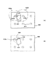
図1は本発明による書類監視装置の実施例を示す概略図である。書類監視装置100は、1つ又はそれ以上の書類の配置に適した構造104を含む。本構造は、例えば、デスクトップ(卓上)又は同様な作業面であり得る。本構造は、本棚の中の棚、又は複写機やプリンタ等のような書類処理装置の書類箱であり得る。
FIG. 1 is a schematic view showing an embodiment of a document monitoring apparatus according to the present invention. The
書類監視装置は、更に、構造104のある領域に関して設けられたセンサ112の配列を含む。図に示されるように、センサは規則的なパターンに並べられている。センサは、図示されているような規則的なパターン以外の任意のパターンで並べられることが可能なことは、理解されるであろう。更に、センサは不規則な又はランダムなパターンに並べられ得ることも、理解されるであろう。
The document monitoring device further includes an array of
検出モジュール106は、センサ112によって生成された信号の集まりを表現する出力信号114を受信する。検出モジュールは、その出力信号に基づいて検出信号を生成する。検出モジュールは、出力信号114の性質に依存して、適切に構成されたコンピュータプロセッサ又はアナログ装置であり得る。以下に説明されるように、本発明の特定の実施例では、出力信号はディジタルであり、検出モジュールはディジタル処理装置であり得る。
The
制御信号118Aは、センサ112に接続され、それらの動作を制御する。本発明の一実施例では、制御信号は検出モジュール106によって生成される。この形態又はコンフィギュレーションは、センサ112及び検出モジュール間の同期動作をとるのに適切である。或いは、図1に示されるように、制御信号118Bは、検出モジュール以外のソースから与えられることも可能である。
The control signal 118A is connected to the
図2(A)〜(C)は、構造104にセンサ112を組み込む代替例を示し、図1に示される2−2線に沿う断面図を示す。図2(A)に示される例は、1つ又はそれ以上の積層体104a,104bを有し、積層体104bの材料の中に設けられたセンサ112を示す。この構造例は、ガラスの保護層104aを有するデスクトップとすることが可能であり、この場合にはセンサがデスクトップ104bの材料(例えば、木)の中に埋め込まれている。図2(B)は、センサが構造の表面102に接しており(flush)、その構造に簡易に埋め込まれている例を示す。図2(C)は、センサが構造の表面102下部に埋め込まれた更に別の例を示す。センサは様々な手法で構造104に組み込まれ得ることが、これらの例から理解されるであろう。
2A to 2C show an alternative example of incorporating the
無線周波数識別システム(RFID)の要素は、本願実施例の特定の形態で使用される。RFIDは識別のための汎用性のある無線ソリューション(解決手段)である。それは、図書館の書籍を追跡することから、牧場の牛の動きを監視することに至る非常に広範な用途を有する。図3(A)、(B)は、3つの要素より成る基本的なRFIDシステムを示し、それらは:アンテナ要素(コイル)313、送受信要素312、及びトランスポンダ(一般に、RFIDタグと呼ばれる)316である。
Elements of a radio frequency identification system (RFID) are used in a particular form of the present embodiment. RFID is a versatile wireless solution for identification. It has a very wide range of uses, from tracking library books to monitoring cattle movement in the ranch. 3A and 3B show a basic RFID system consisting of three elements, which are: an antenna element (coil) 313, a transmit / receive
アンテナ要素313は、タグ316を起動するために無線信号を放出する。アンテナには、様々な形状及びサイズのものを利用することができる。従って、アンテナは、本発明の特定の態様では、図1,図2(A)〜(C)に示されるセンサ112を構成し得ることが、理解されるであろう。
The
しばしば、アンテナ要素313は、典型的にはデコーダモジュールを包含する送受信要素312と共にパッケージ化される。この組み合わせは、リーダ(reader)、応答指令器(interrogator)等として様々に言及される。動作時にあっては、リーダは、その電力出力及び使用される無線周波数に依存して、1インチから数フィード又はそれ以上の任意の範囲に無線電波322(応答指令信号)を発することができる。送受信要素は、アンテナ要素により伝搬される応答指令信号を生成する。
Often, the
RFIDタグが応答指令信号の電磁領域を通過すると、それはその信号に応答し、応答信号316を生成し、応答信号はアンテナ要素313により拾われ又はピックアップされ、送受信要素312に与えられる。トランシーバにおけるデコーダモジュールは、応答信号をデコードし、タグの中にエンコードされているデータを抽出し、そのデータは以後の処理のためにホストコンピュータに伝達される。
When the RFID tag passes through the electromagnetic region of the response command signal, it responds to that signal and generates a
RFIDタグには様々な形状及びサイズのものがある。あるタグは読み取り専用であるが、他のタグは読み書き可能である。例えば、日立製作所によるミューチップ(MU−chip)は0.4mm2程度のチップであり、紙に埋め込まれるのに十分薄く(約60μm)、128ビットの読み取り専用メモリ(ROM)を含む。 RFID tags come in various shapes and sizes. Some tags are read-only, while other tags are readable and writable. For example, a mu chip (MU-chip) by Hitachi, Ltd. is a chip of about 0.4 mm 2 and is thin enough (about 60 μm) to be embedded in paper and includes a 128-bit read-only memory (ROM).
RFIDタグは、能動的(active)又は受動的(passive)の何れにも分類され得る。能動的RFIDタグは、内部電源によって電力供給され、典型的には読み込み/書き込みがなされ、即ちタグデータは再書き込み及び/又は修正され得る。能動的タグのバッテリ供給電力は、一般に、より遠くに至る読み込み範囲をもたらす。当然ながら、トレードオフはサイズの大型化、コストの増加、バッテリの寿命に起因する動作寿命の制約等である。それにもかかわらず、適切な動作条件の下に、能動的タグが本発明にて有用であり得ることが理解されるであろう。 RFID tags can be classified as either active or passive. Active RFID tags are powered by an internal power supply and are typically read / written, ie tag data can be rewritten and / or modified. The battery supply power of an active tag generally results in a farther reading range. Of course, the trade-offs include increased size, increased cost, and operational life constraints due to battery life. Nevertheless, it will be appreciated that active tags may be useful in the present invention under appropriate operating conditions.
受動的RFIDは、別個の外部電源なしに動作し、リーダから送信される応答指令信号から生成される動作電力を取得する。従って受動的タグはアクティブタグよりも計量であり、安価であり、原理的には動作寿命の制約がない。トレードオフは、読み取り範囲が能動的タグより短いこと、及びより高電力のリーダを要すること等である。読み取り専用タグは典型的には受動的タグであり、修正できない固有のデータセット(通常は、32乃至128ビット)と供にプログラムされる。例えば、日立ミューチップは128ビットデータワードで事前にプログラムされ得る。 Passive RFID operates without a separate external power source and obtains operating power generated from a response command signal transmitted from the reader. Thus, passive tags are more metric and cheaper than active tags, and in principle have no operational lifetime constraints. The trade-off is that the reading range is shorter than the active tag and that a higher power reader is required. Read-only tags are typically passive tags that are programmed with a unique data set (usually 32 to 128 bits) that cannot be modified. For example, Hitachi Muchip can be preprogrammed with 128-bit data words.
本発明によれば、物理的な書類がそれらに物理的に関連付けられた1つ又はそれ以上のRFIDタグを有する。多くの(plethora)取り付けプロセスが可能である。複数の書類を一緒にして集めるクリップに、RFIDタグが設けられ得る。例えば、書類クリップは、タグを組み込むことが可能であり、又は止め具(staple)がタグと共に組み込まれ得る。 In accordance with the present invention, physical documents have one or more RFID tags physically associated with them. Many plethora attachment processes are possible. RFID tags may be provided on clips that collect multiple documents together. For example, a document clip can incorporate a tag, or a staple can be incorporated with the tag.
取付は手動でも自動でも行なわれ得る。例えば、複写機はRFIDのタグ付けされた止め具、又はタグの接着剤を供給することが可能であり、まとめられたコピーが止め具でタグ付けされ、又は単一のページ複写が接着性タグでタグ付けされるようにすることが可能である。RFIDタグ(例えば、日立ミューチップ)は用紙自体の中に埋め込まれ得る(タグ付けされた用紙)。 Installation can be done manually or automatically. For example, a copier can supply an RFID tagged stop, or tag adhesive, and a combined copy can be tagged with a stop, or a single page copy can be an adhesive tag It is possible to be tagged with. An RFID tag (eg Hitachi Muchip) can be embedded in the paper itself (tagged paper).
本発明の特定の実施例では、各RFIDタグは、「タグ識別子(tag identifier)」と呼ばれる固有の識別子に関連付けられる。更に、タグが物理的な書類に物理的に関連付けられる場合に、タグ識別子とその物理的な書類に関連する「書類情報」との間の関連付けがなされる。書類情報は、物理的な書類の電子コピー、書類の画像、書類の物理的又は電子形式を識別するリファレンス、物理的書類の電子コピーが見出され得る場所を識別するリファレンス、他の書類に対するリファレンス等より成る。書類情報は、例えば、ある書類がコピーされ得るか否かの認可を示す情報を含み得る。書類情報は、所有者(オーナーシップ)情報、書類修正履歴等を包含し得る。一般に、任意の種類の情報が「書類情報」を形成し得ることが理解されるであろう。 In a particular embodiment of the present invention, each RFID tag is associated with a unique identifier called a “tag identifier”. Further, when a tag is physically associated with a physical document, an association is made between the tag identifier and “document information” associated with the physical document. Document information includes an electronic copy of a physical document, an image of the document, a reference identifying the physical or electronic form of the document, a reference identifying where an electronic copy of the physical document can be found, and a reference to other documents Etc. The document information may include, for example, information indicating authorization as to whether a certain document can be copied. The document information may include owner (ownership) information, document correction history, and the like. In general, it will be understood that any type of information can form “document information”.
書類情報は、書類の作成時間にて収集され得る:例えば、書類が印刷された時、コピーされた時、ファックス送信された時その他の処理された時である。書類情報は、例えば修正がなされる場合、又はコピーが作成される場合等のような書類の寿命(lifetime)の間に集められた情報の蓄積であり得る。データベースシステム(不図示)は、そのような情報を格納するように、又は他の適切な情報管理システムを与えるように設けられる。データベース又は情報管理システムは、タグ識別子及び書類情報の間の対応関係又はマッピングを与えるために使用され得る。 Document information can be collected at document creation time: for example, when a document is printed, copied, faxed, or otherwise processed. The document information may be an accumulation of information gathered during the lifetime of the document, such as when a modification is made or a copy is made. A database system (not shown) is provided to store such information or to provide other suitable information management systems. A database or information management system can be used to provide a correspondence or mapping between tag identifiers and document information.
図4Bは、本願実施例による書類監視がどのようにして行なわれるかを示す。構造104の表面102に、RFIDタグ416に関連付けられる書類があるとする。図に示されるように、書類はその表面における第1位置402、及び架空の第2位置402’を有する。
FIG. 4B shows how the document monitoring according to the present embodiment is performed. Assume that there is a document associated with the
図4Bに示される実施例では、センサ112は、応答指令信号322を生成する送受信回路312より成る応答指令回路である。各センサのアンテナ素子313でピックアップされる応答信号は、送受信回路で検出される。しかしながら、センサの総てが応答信号を検出するわけではない。応答信号は一般的には微弱であるので、特に受動的RFIDタグの場合には弱いので、タグ416により生成された応答信号の送信範囲内のセンサのみが、その信号を検出できる。
In the embodiment shown in FIG. 4B, the
RFIDタグの限定された送信範囲が、図6(A)、(B)に示されている。図6(A)では、応答指令器612の総てが応答指令信号622を送信する(但し、簡単のため、2つの応答指令器612a,612bに関する信号622a,622bのみが示されている。)。関連するRFIDタグ616を有する書類が、電磁輻射にさらされている。図6(B)はタグ616により生成された応答信号624を示す。しかしながら、応答信号の信号強度は弱いので、その範囲は限定され、そのため総ての応答指令器によっては検出されない。むしろ(この場合は)応答信号は応答指令器612aによってのみ検出される。
The limited transmission range of the RFID tag is shown in FIGS. 6 (A) and 6 (B). In FIG. 6A, all of the
図4Aは、図4Bに示される形態で行なわれる処理の上位概念的フローチャートを示す。各センサ112は、ステップ402にて、時刻t0にて応答指令信号を送信する。上述したように、タグ416の応答信号は、タグの送信範囲内にあるセンサによってのみ検出される(ステップ404)。応答信号を検出するこれらのセンサはそれぞれ検出出力信号を生成し、その信号は典型的には例えば識別コードのようなタグ416に格納されるいくつかの情報より成る。センサ出力信号の収集は、出力信号114によって全体的に表現されている(図1)。検出モジュール106は、第1群のセンサ出力信号を受信し、書類の第1位置402を示す第1情報としてそれらを格納する(ステップ406)。
FIG. 4A shows a high-level conceptual flowchart of the processing performed in the form shown in FIG. 4B. In
書類が動いた時間をt1(>t0)とする。これは、位置402’に示される書類(架空の又は波線)により示される。時刻t2(>t1)にて、第2応答指令信号が、センサ112の送受信回路により送信され(ステップ402)、他のセンサ群がタグ416から生成された応答信号を検出する(ステップ404)。第2群のセンサ出力信号は出力信号114として生成され、書類の第2の位置402’を示す第2情報として検出モジュール106に格納される(ステップ406)。第1センサ出力信号及び第2センサ出力信号に基づいて、書類の動きが決定され得る(ステップ412)。
The time when the document moves is assumed to be t 1 (> t 0 ). This is indicated by the document (imaginary or wavy) shown at position 402 '. At time t 2 (> t 1 ), the second response command signal is transmitted by the transmission / reception circuit of the sensor 112 (step 402), and another sensor group detects the response signal generated from the tag 416 (step 404). ). A second group of sensor output signals is generated as
本発明の特定の実施例では、検出モジュール106は、各信号にセンサの場所を示す情報を関連付けることで、センサ出力信号を処理することができる。例えば、センサ450から受信したセンサ出力信号は、座標(A,1)によって区別される場所に関連付けられる。このようにして、時刻t0にてタグ416の応答信号を検出したセンサの場所と、時刻t2にて応答信号を検出したセンサの場所とを比較することで、書類の動きが決定される。
In particular embodiments of the present invention, the
或いは、検出モジュール106は、センサ出力信号をセンサ112それら自身に関連付けることで、センサ出力信号を処理することができる。例えば、センサ出力信号は、タグ識別子を示す、即ちそのタグを区別する情報を含み得る。書類の動きは、第1群のセンサ出力信号から取得したタグ識別子を、第2群のセンサ出力信号から取得したタグ識別子と比較することで検出され得る。
Alternatively, the
図5(A)〜(C)は、本発明の別の実施例による書類監視装置を示す。装置500は書類の配置に適切な構造504を包含する。複数の受信要素512bはその構造のある領域の回りに設けられる。図5(A)〜(C)は、受信要素がどのようにして構造504と協調するかを例示する。受信要素の出力は、出力信号114として収集され提供される。本発明の実施例では、単独の送信回路512aが、制御信号518に応答して応答指令信号522を送信するように設けられる。RFIDタグ516は、構造504の表面に設けられるように示される。
5A to 5C show a document monitoring apparatus according to another embodiment of the present invention.
受信要素512bは、タグ516から応答信号を送信するアンテナ要素(例えば、図3(A)の313)より成る。受信要素は、更に、アンテナでピックアップした応答信号を検出するための回路(図示せず)を包含する。受信要素は、図3(A)、(B)に示されるもののような従来の応答指令装置の一部を形成する。本発明のこの特定の実施例では、従来の応答指令器の送受信要素が、送信回路要素512aと複数の受信回路要素512bに分離されている。複数の受信要素は構造504の周囲に設けられる。
The receiving
図5(B)、(C)は、応答指令信号522による応答指令の後に、タグ516からの応答信号524の伝搬の様子を示す。図5(C)は図5(B)のC−C線に沿う平面図である。各図は応答信号の限定された範囲を示し、全部よりは少ない受信要素512bによる信号の検出を示し、この場合に、受信要素A−Dが応答信号を検出するように描かれている。タグ516は、波線で示される架空の位置の書類502に物理的に関連付けられるように示される。
FIGS. 5B and 5C show the propagation of the response signal 524 from the
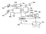
図7は、本発明の更なる別の実施例による書類監視の様子を示すブロック図である。この図は、書類処理装置700を示す。例えば、これはコピー機、ファクシミリ装置又はプリンタ等であり得る。書類処理装置は、書類の山として概念的に表現される、書類ソース701を有する。入力要素732は書類ソースを処理する。例えば、コピー機又はファクシミリ装置(fax)の場合に、書類ソースは、コピーされる物理的な用紙であり得るし、入力要素は画像処理装置であり得る。書類ソースは、データ処理装置へのデータ接続部でさえあり得るし、その場合に書類はコピー機又はファクシミリ装置に電子的に与えられる。プリンタの場合には、書類ソース701は、書類サーバ又は何らのデータ処理装置へのネットワーク接続のようなものとすることが可能であり、入力要素は、書類を構成する電子データを受信留ためのネットワークインターフェース要素とすることが可能である。
FIG. 7 is a block diagram showing a state of document monitoring according to still another embodiment of the present invention. This figure shows a
入力要素732は、コピー又はプリントアウトを作成するために書類生成要素730に接続される。書類ソース703は、書類の山を書類生成要素に供給する。本願実施例では、RFIDタグは、書類生成要素により生成された書類に物理的に関連付けられる。例えば、接着性タグの供給機構は、書類生成要素の中に組み込まれることが可能であり、その書類生成要素は、コピー動作又は印刷動作中にそれが通過する場合に、タグを紙のストック(stock)に取り付ける。他の例では、RFIDタグより成る止め具のマガジン(magazine)を有する止め具機構が、複数ページの書類を束ねてタグ付けすることができる。或いは、書類ストック自体が、用紙に直接的に組み入れられたRFIDを有する「タグ付け用紙」であり得る。
ファクシミリ伝送装置の場合には、書類生成要素730は、遠隔したファクシミリ送信装置に接続し、その遠隔回路に書類の電子コピー(FAX)を通信するデータ通信回路より成る。
In the case of a facsimile transmission device, the
書類生成装置700は、例えば、コピーされた文書、印刷された文書のようなコピー又は原稿を受けるために設けられた、適切な出力トレイ734を包含する。
検出モジュール706は、入力要素732及び出力トレイ734の一方又は両方に対する信号接続部714a,714bを包含する。以下に説明されるように、信号接続部は、入力要素及び/又は出力トレイに存在する書類についての情報を与える。検出モジュールは信号707を記録要素708及び適切なサーバシステム710に供給する。
The
記録要素708には、各々を識別する記録情報が用意される。記録要素は、キー入力用に又は彼らの身元を示す情報を与えるために使用する入力装置を含むことが可能であり、それは書類処理装置700を起動するために以後使用される。記録要素は、個々の画像709を生成する画像記録装置を包含し得る。画像はその後にサーバ710に供給され、サーバは個々の身元を判別するために適切な画像分析を実行することができる。
In the
一実施例では、入力要素732は、RFIDタグを包含するソース書類を検出するRFID応答指令装置732aを包含する。制御信号718は、例えば応答指令信号を生成するために、応答指令装置を制御するために入力要素に与えられる。コピー機の場合は、記録要素708はユーザを示す情報を取得し得る。その情報は識別コード又はユーザの画像であり得る。ソース書類701がコピー機に与えられる場合に、入力要素732はソース書類内のタグを検出し、適切な信号714aを検出モジュール706に送信する。検出モジュールに与えられた信号は、タグ識別子を包含し得る。記録よそにより供給された識別情報及び検出モジュールにより供給されたタグ情報は、サーバ710によって処理され得る。サーバはその後に受信した情報に基づいて(適切な制御信号、例えば718を利用して)コピー機能をイネーブルにする。
In one embodiment,
例えば、タグ情報は、その書類を識別する何らかの情報に対応付けられる。上述したように、この情報は、書類識別子、書類の画像等の任意のものであり得る。また、タグ情報は、その特定の書類に関して特定のユーザにどのような動作(コピーをとること、特定の宛先にファクシミリ送信すること等)が許可されているかを指示することに関連する許可情報に対応付けられ得る。一般に、書類処理装置700に要求される動作は、記録要素によって収集された情報に基づいて、及び入力要素732に含まれるRFID応答指令装置732aにより受信された情報に基づいて、イネーブルされ又はディセーブルされ得る。
For example, the tag information is associated with some information for identifying the document. As described above, this information can be any document identifier, document image, or the like. Also, the tag information is permission information related to instructing a specific user what operation (copying, facsimile transmission to a specific destination, etc.) is permitted for the specific document. Can be associated. In general, the operations required of the
本発明の更なる実施例では、再書き込み可能なRFIDチップ(タグ)におけるハッシュコードの組み合わせである。ハッシュコード(例えば、md5ハッシュアルゴリズムについては、“http://userpages.umbc.edu/〜mabzugl/cs/md5/md5.html”のウェブサイトを参照。)は、印刷される前に書類(例えば、ポストスクリプト(ps)又はスキャンされた画像)のディジタル表現に適用され得る。md5ハッシュは、固有の書類全体につき固有の128ビット出力を形成する。ハッシュコードはRFIDチップに格納され得る。後に、2つの物理的な書類が厳密に同じ内容であることを確認する必要のあるユーザは、単にRFIDチップをスキャンし、ハッシュコードを比較することができる。2つの書類を並べた目視的比較は困難であり、特に書類の2つの態様(バージョン)の間に小さな差異しかない場合(例えば、数語しか相違しないとき)は特に困難であることに留意を要する。しかしながら、ハッシュコードが使用されるならば、その比較は極めて容易である。また、比較される2つの書類が、異なるフォーマット規則(例えば、1列フォーマット又は2列フォーマット)に従って、異なる場所で異なる人々によって異なる時間に印刷され得ることにも留意を要する。そのような2つの書類を比較するのにハッシュコードを利用すると、非常に正確になる。また、その比較は異なる人々によって異なる場所でなされ得るが、共通の通信チャネルを共用し得ることにも留意を要する。これは、同一の契約書が異なる人々により異なる場所で印刷されるところの契約締結プロセスの一部になり得る。md5ハッシュコードは、チップから読み出され、署名ライン近辺にてその契約書上に印刷される(即ち、手書きされる)。署名された契約書の画像は署名者間で交換され得る。各自はその契約内容が厳密に同じであることを保証し得る。 In a further embodiment of the invention, a hash code combination in a rewritable RFID chip (tag). The hash code (eg, for the md5 hash algorithm, see the website “http://userpages.umbc.edu/˜mabzugl/cs/md5/md5.html”) , Postscript (ps) or scanned images). The md5 hash forms a unique 128-bit output for the entire unique document. The hash code can be stored on the RFID chip. Later, a user who needs to verify that the two physical documents are exactly the same can simply scan the RFID chip and compare the hash codes. Note that visual comparison of two documents side by side is difficult, especially if there are only small differences between the two forms (versions) of the document (eg when only a few words are different). Cost. However, if hash codes are used, the comparison is very easy. It should also be noted that the two documents to be compared can be printed at different times by different people at different times according to different formatting rules (e.g., one-column format or two-column format). Using hash codes to compare two such documents is very accurate. It should also be noted that the comparison may be made by different people at different locations, but may share a common communication channel. This can be part of the contract conclusion process where the same contract is printed by different people at different locations. The md5 hash code is read from the chip and printed on the contract (ie handwritten) near the signature line. Images of signed contracts can be exchanged between signers. Each can guarantee that the contract is exactly the same.
本発明の更なる別の実施例では、出力トレイ734が、例えば図1に示されるように設けられた1つ又はそれ以上の応答指令装置734aに設けられる。本実施例では、RFIDタグに物理的に関連する任意の書類は、その出力トレイ内の動きに関して監視され得る。これは、書類の位置変化又はその移行を監視することを含む。重要な事案が出力トレイに残っている場合に、位置変化を検出することが望ましく、その位置変化は、誰かがその重要情報を見るためにいくつかの書類を動かしたことを示し得るものである。
In yet another embodiment of the present invention,
移動が検出されると、上述したように、応答指令装置から適切な信号が形成される。応答指令出力信号714bは検出モジュール706に送信される。検出モジュールはその後に記録装置708に信号送信し、その事象(イベント)を記録するためにその近辺の音声及び/又は視覚的情報を捕捉し、及びその事象を引き起こした者を把握する。この情報は以後出力トレイから検出モジュールによって取得された情報と共にサーバ710に送信され、どのような書類が動かされたか(又は移行したか)、その事象がいつ起こったか、及び/又はその事象を引き起こした者を記録する。
When movement is detected, an appropriate signal is generated from the response command device as described above. The response
サーバ710は中央データベースとして機能し、上述した書類履歴を格納する。書類履歴は様々な手法で蓄積され得る。例えば、書類の「無意識的捕捉(unconscious capture)」は、ユーザが意図的に起動せずに自動的な書類捕捉が起こる技法である。そのような技法は、1999年7月6日に出願された米国特許第5,978,477号及び米国特許出願第09/347,953号に開示され、その全内容が本願の参考に供される。当然に、他の書類捕捉法が書類履歴データベースを形成するために使用され得る。蓄積された履歴は、書類を抽出する及びそれらのセキュリティ履歴を閲覧する内容に基づいて、探索され得る。
The
本発明による書類セキュリティシステムの望まれる特徴は、書類に関して、RFIDチップにてそれらのセキュリティ履歴を搬送できることである。これは、再書き込み可能なRFIDチップを利用することで達成される。そして、本発明の他の実施例では、再書き込み可能なRFIDタグは書類履歴の一部を格納するために使用され得る。図7を参照するに、RFID応答指令装置732a及び/又は734aは、書類に設けられた再書き込み可能なRFIDタグにおける情報格納部にふさわしい信号を生成するよう構成され得る。
A desirable feature of the document security system according to the present invention is that for documents, their security history can be carried by the RFID chip. This is achieved by utilizing a rewritable RFID chip. And in other embodiments of the invention, a rewritable RFID tag can be used to store a portion of the document history. Referring to FIG. 7,
再書き込み可能なRFIDは、書類が印刷された時、それが出力トレイから動かされた時、それを動かした者、それが机上で動いた時等のような情報をユーザが容易に判別することを可能にする。チップにセキュリティ履歴を格納することは、ネットワーク接続又は中央データベースからの抽出を要しないので、その情報への以後のアクセスを簡易化する。同様な履歴情報が、再書き込み可能なチップを有しない書類(例えば、単なる読み取り専用チップ)についても計算されることが理解されるであろう。そのような情報は、その情報の格納及び抽出に関連する中央データベース(例えば、図7の要素710)に格納され得る。
Re-writable RFID allows the user to easily identify information such as when a document is printed, when it is moved from the output tray, when it is moved, when it is moved on the desk, etc. Enable. Storing security history on the chip simplifies subsequent access to that information because it does not require network connection or extraction from a central database. It will be appreciated that similar historical information is calculated for documents that do not have a rewritable chip (eg, just a read-only chip). Such information may be stored in a central database (eg,
本発明の実施例では、書類のセキュリティ履歴は、書類が存在していた場所、そのような場所に存在していた時、そのような場所でそれが動かされた時、及びそれらの場所からそれが動かされた時等を表現する情報を包含し得る。そのような履歴の入力例は、例えば:
「15ページの書類215624」印刷プリンタ_8780「1998年8月12日」15:47
である。
In an embodiment of the present invention, the security history of a document is the location of the document, when it was in such a location, when it was moved in such a location, and from that location. It may contain information that expresses when is moved. An example of such a history entry is:
“15-page document 215624” printing printer — 8780 “August 12, 1998” 15:47
It is.
これは、その書類を一般的に15ページ書類として識別し、中央データベースからその書類内容を抽出するために使用され得る固有の識別番号に関連付ける。また、それを印刷した装置(プリンタ_8780)及びそれが印刷された日時をも見分ける。当然に、この情報は、チップに要求される格納スペースを削減するためにジップ(zip)のような一般的に周知の技法で圧縮され得る。 This generally identifies the document as a 15 page document and associates it with a unique identification number that can be used to extract the document contents from a central database. It also identifies the device that printed it (printer — 8780) and the date and time it was printed. Of course, this information can be compressed with commonly known techniques such as zip to reduce the storage space required on the chip.
その履歴の中の次の入力は、書類がプリンタの出力トレイから動かされた日時を示すであろう:
「15ページ書類215624」移動プリンタ_8780「1998年8月12日」16:08。
The next entry in the history will show the date and time the document was moved from the printer output tray:
“15-page document 215624” moving printer — 8780 “August 12, 1998” 16:08.
これは、その書類に取り付けられているRFIDチップの動きを監視する応答指令装置732a及び/又は734aにより実行され得る。この装置は、書類が出力トレイから動かされた時点でチップのメモリに書き込みを行なう回路を包含し得る。
This can be performed by a
しかしながら、トレイから物理的に移動する速度が、その回路の動作速度を上回ることもあり得る。そこで別の実施例では、その装置は、チップ内で最新の履歴入力(「動かされた」記録)を定常的に再書き込みする再書き込み回路を包含し得る。これは、それは動かされる以前であるが書類が出力トレイ内にある場合に行なわれ得る。このように、たとえどのように速く書類が動かされたとしても、移動した時間が記録され得る。 However, the speed of physical movement from the tray may exceed the operating speed of the circuit. Thus, in another embodiment, the device may include a rewrite circuit that steadily rewrites the latest history entry ("moved" record) in the chip. This can be done if it is before being moved but the document is in the output tray. In this way, no matter how fast the document is moved, the time moved can be recorded.
図8は再書き込み回路の再書き込み手順のステップに関する上位概念的フローチャートである。書類が書類セキュリティシステムに到来すると、それはステップ802にてRFIDタグ内の項目を読み出す。ステップ801にて、そのタグが「移動した」記録を包含しないことが判定されると、ステップ806に進む。タグ内に「移動した」記録が存在する場合は、ステップ803にて履歴再書き込み回路は、最新の履歴更新以来の時間量が閾値t2を超えているか否かを判別する。これらの条件が満たされるならば、新たな「移動した」記録が履歴リストに付加され(ステップ806)、更新プロセスが再び始まる(ステップ810)。ステップ803にて閾値t2を上回らない場合は、格納済みの記録されている時間記録は、ステップ804にて、現在の時間の記録によって単に置換される。同一の更新アルゴリズムが、出力トレイ監視アルゴリズム、デスクトップセキュリティ態様その他の類似する書類追跡システムに使用され得ることが、理解されるであろう。しかしながら、時間閾値は相違し得る。
FIG. 8 is a high-level conceptual flowchart regarding the steps of the rewrite procedure of the rewrite circuit. When the document arrives at the document security system, it reads the item in the RFID tag at
また、このアルゴリズムの変形例(図9に示される)は、ステップ902にて、セキュリティシステムに取り付けられたカメラによって捕捉された「移動した」記録における画像をも格納し得る。多くの不適切な画像が捕捉されたとしても、本アルゴリズムは、「移動した」記録に最終的に格納された画像が、装置からその書類を動かした者によることを保証する。
A variation of this algorithm (shown in FIG. 9) may also store an image in a “moved” recording captured at
100 書類監視装置
102 表面
104 構造
106 検出モジュール
112 センサ
114 出力信号
116 検出信号
118 制御信号
312 送受信要素
313 アンテナ要素
316 トランスポンダ
402 第1位置
402’ 第2位置
416 RFIDタグ
450 センサ
500 装置
504 構造
512a 送信要素
512b 受信要素
514 出力信号
516 タグ
522 応答指令信号
524 応答信号
602 書類
612 応答指令器
616 RFIDタグ
622 信号
624 応答信号
700 書類処理装置
701 書類ソース
703 用紙ソース
706 検出モジュール
708 記録要素
709 画像
710 サーバ
714 信号接続部
718 制御信号
730 書類生成要素
732 入力要素
734 出力トレイ
DESCRIPTION OF
Claims (37)
1以上の書類を置くのに適した構造の或る領域に設けられ、前記書類に物理的に付加された無線周波数識別タグより生成された応答信号を検出することに応じて、センサ出力信号を生成する複数のセンサと、
前記センサからのセンサ出力信号を受信するように結合され、前記構造に設けられた書類の移動を示す検出信号を生成する検出モジュールと
を有し、第1群のセンサにより作成された第1群のセンサ出力信号が、前記書類の第1の位置に関連付けられ、第2群のセンサにより作成された第2群のセンサ出力信号が、前記書類の第2の位置に関連付けられ、
前記検出信号が前記第1群のセンサ及び前記第2群のセンサに基づいて作成されること
を特徴とする書類監視装置。 A document monitoring device ,
In response to detecting a response signal generated by a radio frequency identification tag provided in a region of a structure suitable for placing one or more documents and physically attached to the document, the sensor output signal is Multiple sensors to generate,
A detection module coupled to receive a sensor output signal from the sensor and generating a detection signal indicative of movement of a document provided in the structure ;
A first group of sensor output signals created by the first group of sensors is associated with a first position of the document, and a second group of sensor output signals created by the second group of sensors is , Associated with a second position of the document,
The document monitoring apparatus, wherein the detection signal is generated based on the first group of sensors and the second group of sensors.
無線周波数識別タグから応答指令信号を生成するのに適した応答指令信号を生成及び送信する送信器と、
1以上の書類を置くのに適した構造の或る領域に設けられ、前記書類の近辺でセンサ出力信号を生成することで応答し、前記書類に物理的に付加された無線周波数タグが前記応答指令信号を受けることで応答信号を生成し、前記無線周波数タグが生成した前記応答信号を検出することに応じて、センサ出力信号を生成する複数のセンサと、
前記構造に置かれた書類の動きを示す検出信号を生成するために、前記センサからセンサ出力信号を受信するように接続される検出モジュールと
を有し、第1群のセンサにより作成された第1群のセンサ出力信号が、前記書類の第1の位置に関連付けられ、第2群のセンサにより作成された第2群のセンサ出力信号が、前記書類の第2の位置に関連付けられ、
前記検出信号が、前記第1群のセンサが前記第2群のセンサと同じであるか否かの判定に基づいて形成されること
を有することを特徴とする書類監視装置。 A document monitoring device ,
A transmitter for generating and transmitting a response command signal suitable for generating a response command signal from a radio frequency identification tag;
Responsive by generating a sensor output signal in the vicinity of the document provided in a region suitable for placing one or more documents, a radio frequency tag physically attached to the document includes the response A plurality of sensors for generating a sensor output signal in response to detecting the response signal generated by the radio frequency tag by generating a response signal by receiving a command signal;
A detection module connected to receive a sensor output signal from the sensor to generate a detection signal indicative of movement of a document placed on the structure ;
A first group of sensor output signals created by the first group of sensors is associated with a first position of the document, and a second group of sensor output signals created by the second group of sensors is , Associated with a second position of the document,
The document monitoring apparatus , wherein the detection signal is formed based on a determination as to whether or not the first group of sensors is the same as the second group of sensors .
を特徴とする請求項14記載の書類監視装置。 15. The document monitoring apparatus according to claim 14, wherein the sensor comprises an antenna and a receiving circuit suitable for detecting the response signal.
前記複数のセンサが、第1の期間内に、1以上の第1の応答指令信号を送信し、該第1の応答指令信号に応答する無線周波数識別タグから1以上の第1の応答信号を受信するステップと
前記複数のセンサが、第2の期間内に、1以上の第2の応答指令信号を送信し、該第2の応答指令信号に応答する前記無線周波数識別タグからの1以上の第2の応答信号を受信するステップと、
前記第1の応答信号を受信した第1群のセンサが生成した第1のセンサ出力信号及び前記第2の応答信号を受信した第2群のセンサが生成した第2のセンサ出力信号に基づいて、前記書類の位置が、前記第1の期間及び前記第2の期間の間に変化したか否かを判定するステップと
を有することを特徴とする方法。 A method of monitoring a document physically associated with at least one radio frequency identification tag by means of a plurality of sensors provided in an area of a structure suitable for placing one or more documents , comprising:
The plurality of sensors transmit one or more first response command signals within a first period, and receive one or more first response signals from a radio frequency identification tag that responds to the first response command signal. Step to receive and
The plurality of sensors transmit one or more second response command signals within a second period, and the one or more second responses from the radio frequency identification tag responding to the second response command signals Receiving a signal ; and
Based on the second sensor output signal sensor of the second group was formed which receives the first sensor output signal and the second response signal is a first group of sensors were produced, which has received the first response signal , how the position of the document, characterized in that a step determines whether or not change during the first period and the second period.
前記無線周波数識別タグが前記応答指令に応じて生成する1以上の応答信号を、前記無線周波数識別タグが設置された近辺に並べられた複数の場所で前記応答信号を検知する複数のセンサと、
前記無線周波数識別タグが前記領域の第1の位置にある場合に前記応答信号を受信する第1群のセンサが生成する第1のセンサ出力信号及び前記無線周波数識別タグが前記領域の第2の位置にある場合に前記応答信号を受信する第2群のセンサが生成する第2のセンサ出力信号に基づいて、前記領域における前記無線周波数識別タグの位置の変化を検出する検出手段と
を備えることを特徴とする装置。 An apparatus for monitoring a document radio frequency identification tag physically associated with the response command that gives a response command to the radio frequency identification tag installed on a region of a structure suitable for placing one or more documents Means ,
A plurality of sensors for detecting the radio frequency identification tag is one or more of the response signals generated in response to the interrogation, the response signal at a plurality of locations that ordered in the vicinity of the radio frequency identification tag is installed,
A first sensor output signal generated by a first group of sensors that receive the response signal when the radio frequency identification tag is in a first position of the area and the radio frequency identification tag is a second of the area. based on the second sensor output signal by the second group of sensors for receiving the response signal is generated when in position, be provided with a detecting means for detecting a change in the position of the radio frequency identification tag in the region and wherein the.
無線周波数識別タグが物理的に関連付けられた1以上の書類を受領するのに適した書類受領領域付近に設けられ、書類に隣接して応答し、書類を示すセンサ出力信号を生成するよう動作する複数のセンサと、
前記領域に置かれた書類の動きを示す検出信号を生成するために、前記センサで生成される前記センサ出力信号を受信するように接続された検出モジュールと、
前記検出信号を受信し、ユーザを表現するユーザ識別情報を取得するように動作可能に接続される記録装置と
を有し、前記書類に物理的に関連付けられた無線周波数識別タグは前記応答指令信号に応じて応答信号を生成し、
前記センサは前記応答信号を検出し、第1群のセンサ出力信号が前記書類の第1位置に関連付けられ、第2群のセンサ出力信号が前記書類の第2位置に関連付けられ、
前記検出信号が前記第1群のセンサ出力信号及び前記第2群のセンサ出力信号に基づいて作成される
ことを特徴とする書類監視装置。 A document monitoring device in the document processing apparatus, and at least one interrogation source to generate a response command signal,
A radio frequency identification tag is provided in the vicinity of the document receiving area suitable for receiving one or more physically associated documents and is operable to respond adjacent to the document and generate a sensor output signal indicative of the document. Multiple sensors ,
A detection module connected to receive the sensor output signal generated by the sensor to generate a detection signal indicative of movement of a document placed in the area ;
A recording device operably connected to receive the detection signal and obtain user identification information representing the user ;
The a, a radio frequency identification tag physically associated with the document to generate a response signal in response to said interrogation signal,
The sensor detects the response signal, the sensor output signal of the first group is associated with a first position before Kisho such, the sensor output signal of the second group is associated with a second position before Kisho acids,
The document monitoring apparatus, wherein the detection signal is generated based on the first group of sensor output signals and the second group of sensor output signals.
Applications Claiming Priority (1)
| Application Number | Priority Date | Filing Date | Title |
|---|---|---|---|
| US10/235,030 US7129840B2 (en) | 2002-09-03 | 2002-09-03 | Document security system |
Publications (3)
| Publication Number | Publication Date |
|---|---|
| JP2004094949A JP2004094949A (en) | 2004-03-25 |
| JP2004094949A5 JP2004094949A5 (en) | 2007-05-24 |
| JP4002547B2 true JP4002547B2 (en) | 2007-11-07 |
Family
ID=31977503
Family Applications (1)
| Application Number | Title | Priority Date | Filing Date |
|---|---|---|---|
| JP2003300099A Expired - Fee Related JP4002547B2 (en) | 2002-09-03 | 2003-08-25 | Document security system |
Country Status (2)
| Country | Link |
|---|---|
| US (1) | US7129840B2 (en) |
| JP (1) | JP4002547B2 (en) |
Families Citing this family (56)
| Publication number | Priority date | Publication date | Assignee | Title |
|---|---|---|---|---|
| JP4640629B2 (en) * | 2002-08-28 | 2011-03-02 | 富士ゼロックス株式会社 | Post-processing device and staple needle |
| US7424974B2 (en) * | 2002-09-03 | 2008-09-16 | Ricoh Company, Ltd. | Techniques that facilitate tracking of physical locations of paper documents |
| US6860422B2 (en) * | 2002-09-03 | 2005-03-01 | Ricoh Company, Ltd. | Method and apparatus for tracking documents in a workflow |
| US7506250B2 (en) * | 2002-09-03 | 2009-03-17 | Ricoh Company, Ltd. | Techniques for determining electronic document information for paper documents |
| US7652555B2 (en) * | 2002-09-03 | 2010-01-26 | Ricoh Company, Ltd. | Container for storing objects |
| US7884955B2 (en) * | 2002-09-03 | 2011-02-08 | Ricoh Company, Ltd. | Techniques for performing actions based upon physical locations of paper documents |
| US7712675B2 (en) * | 2003-01-15 | 2010-05-11 | Hewlett-Packard Development Company, L.P. | Physical items for holding data securely, and methods and apparatus for publishing and reading them |
| JP3738761B2 (en) * | 2003-01-16 | 2006-01-25 | コニカミノルタビジネステクノロジーズ株式会社 | Composite image processing device |
| US7774268B2 (en) * | 2003-03-03 | 2010-08-10 | The Tb Group, Inc. | System, method, and apparatus for identifying and authenticating the presence of high value assets at remote locations |
| US7671744B2 (en) * | 2003-03-03 | 2010-03-02 | Veroscan, Inc. | Interrogator and interrogation system employing the same |
| US8063760B2 (en) * | 2003-03-03 | 2011-11-22 | Veroscan, Inc. | Interrogator and interrogation system employing the same |
| US7541933B2 (en) * | 2003-03-03 | 2009-06-02 | Veroscan, Inc. | Interrogator and interrogation system employing the same |
| US8174366B2 (en) | 2003-03-03 | 2012-05-08 | Veroscan, Inc. | Interrogator and interrogation system employing the same |
| US7764178B2 (en) | 2003-03-03 | 2010-07-27 | Veroscan, Inc. | Interrogator and interrogation system employing the same |
| US8542717B2 (en) | 2003-03-03 | 2013-09-24 | Veroscan, Inc. | Interrogator and interrogation system employing the same |
| US7893840B2 (en) | 2003-03-03 | 2011-02-22 | Veroscan, Inc. | Interrogator and interrogation system employing the same |
| US7019650B2 (en) * | 2003-03-03 | 2006-03-28 | Caducys, L.L.C. | Interrogator and interrogation system employing the same |
| US7246754B2 (en) * | 2004-02-18 | 2007-07-24 | Hewlett-Packard Development Company, L.P. | Secure currency |
| JP2007526586A (en) | 2004-03-03 | 2007-09-13 | ケイデュシィズ エル エル シィ | Interrogation system using interrogators and the like |
| US7522046B2 (en) * | 2004-03-17 | 2009-04-21 | Sap Aktiengesellschaft | Document management |
| US20060020803A1 (en) * | 2004-07-06 | 2006-01-26 | Zih Corp. | Systems and methods for authentication of items or documents |
| JP4055756B2 (en) * | 2004-08-17 | 2008-03-05 | コニカミノルタビジネステクノロジーズ株式会社 | Image forming apparatus, image forming method, and image forming program |
| US7501948B2 (en) * | 2004-09-29 | 2009-03-10 | Lone Star Ip Holdings, Lp | Interrogation system employing prior knowledge about an object to discern an identity thereof |
| JP2006110858A (en) * | 2004-10-14 | 2006-04-27 | Konica Minolta Business Technologies Inc | Image forming apparatus, method of forming image, and program for controlling the same |
| KR100582730B1 (en) * | 2004-10-26 | 2006-05-23 | 삼성전자주식회사 | apparatus and method for transmitting data in facsimile |
| JP2006124123A (en) * | 2004-10-29 | 2006-05-18 | Yoshiyuki Kajino | Filing security system and article security system |
| US7382254B2 (en) * | 2004-12-03 | 2008-06-03 | Intel Corporation | Storage medium having RFID tag and methods for using same |
| JP4165504B2 (en) * | 2004-12-21 | 2008-10-15 | コニカミノルタビジネステクノロジーズ株式会社 | Image forming apparatus, image forming method, and image forming program |
| JP4690756B2 (en) * | 2005-03-25 | 2011-06-01 | 東芝テック株式会社 | Wireless tag reader / writer |
| JP4714496B2 (en) * | 2005-03-30 | 2011-06-29 | 富士通株式会社 | Disclosure review support program, information management system |
| US7414532B2 (en) * | 2005-04-20 | 2008-08-19 | Nordson Corporation | Method of attaching RFID tags to substrates |
| US7280044B2 (en) * | 2005-04-25 | 2007-10-09 | Xerox Corporation | RFID activated paperclip tag |
| KR100737408B1 (en) * | 2005-04-26 | 2007-07-09 | 이철호 | Scrap process monitoring system of security documents through network |
| US7565358B2 (en) * | 2005-08-08 | 2009-07-21 | Google Inc. | Agent rank |
| US8576077B2 (en) * | 2005-08-09 | 2013-11-05 | Koninklijke Philips N.V. | System as well as method for protecting an item to be secured |
| US7541925B2 (en) * | 2005-10-24 | 2009-06-02 | International Business Machines Corporation | Mapping system and method for determining optimal radio transponder placement |
| US7740179B2 (en) * | 2005-12-15 | 2010-06-22 | Mediamark Research, Inc. | System and method for RFID-based printed media reading activity data acquisition and analysis |
| US7959086B2 (en) * | 2005-12-15 | 2011-06-14 | Gfk Mediamark Research & Intelligence, Llc | System and method for RFID-based printed media reading activity data acquisition and analysis |
| JP4661620B2 (en) * | 2006-02-14 | 2011-03-30 | 富士ゼロックス株式会社 | Document management apparatus and program |
| US7518516B2 (en) * | 2006-03-27 | 2009-04-14 | Neology, Inc. | Systems and methods for managing inventory of items held in a cabinet using radio frequency identification (RFID) |
| WO2007112413A2 (en) | 2006-03-27 | 2007-10-04 | Neology, Inc. | Systems and methods for managing inventory of items held in a cabinet using radio frequency identification (rfid) |
| US8179265B2 (en) | 2006-06-21 | 2012-05-15 | Neology, Inc. | Systems and methods for breakaway RFID tags |
| US7733220B2 (en) * | 2006-10-05 | 2010-06-08 | Northrop Grumman Corporation | System and methods for detecting change in a monitored environment |
| JP2008158684A (en) * | 2006-12-21 | 2008-07-10 | Konica Minolta Business Technologies Inc | Image monitoring system, image monitoring method, and image monitoring program |
| US7755491B2 (en) | 2007-08-13 | 2010-07-13 | Veroscan, Inc. | Interrogator and interrogation system employing the same |
| US7724142B2 (en) * | 2007-09-27 | 2010-05-25 | Intermec Ip Corp. | Systems and methods for wirelessly marking media |
| US7502619B1 (en) * | 2008-01-22 | 2009-03-10 | Katz Daniel A | Location determination of low power wireless devices over a wide area |
| US20090314836A1 (en) * | 2008-06-18 | 2009-12-24 | Xerox Corporation | Automatic print job tracking |
| US8610574B2 (en) | 2009-06-15 | 2013-12-17 | Gerald Isaac Kestenbaum | Item storage and tracking system |
| US8606792B1 (en) | 2010-02-08 | 2013-12-10 | Google Inc. | Scoring authors of posts |
| US8325019B2 (en) | 2010-09-13 | 2012-12-04 | Ricoh Company, Ltd. | Motion tracking techniques for RFID tags |
| US9035774B2 (en) | 2011-04-11 | 2015-05-19 | Lone Star Ip Holdings, Lp | Interrogator and system employing the same |
| TW201827077A (en) | 2016-12-28 | 2018-08-01 | 美商建南德克公司 | Treatment of advanced her2 expressing cancer |
| LT3570884T (en) | 2017-01-17 | 2020-12-10 | Genentech, Inc. | Subcutaneous her2 antibody formulations |
| AU2018227788B2 (en) | 2017-03-02 | 2021-04-22 | F. Hoffmann-La Roche Ag | Adjuvant treatment of HER2-positive breast cancer |
| WO2018200505A1 (en) | 2017-04-24 | 2018-11-01 | Genentech, Inc. | Erbb2/her2 mutations in the transmbrane or juxtamembrane domain |
Family Cites Families (73)
| Publication number | Priority date | Publication date | Assignee | Title |
|---|---|---|---|---|
| US4862160A (en) | 1983-12-29 | 1989-08-29 | Revlon, Inc. | Item identification tag for rapid inventory data acquisition system |
| US5287414A (en) | 1991-06-21 | 1994-02-15 | Esselte Pendaflex Corporation | Coded file locator system |
| US6130621A (en) | 1992-07-09 | 2000-10-10 | Rsa Security Inc. | Method and apparatus for inhibiting unauthorized access to or utilization of a protected device |
| US5666490A (en) | 1994-05-16 | 1997-09-09 | Gillings; Dennis | Computer network system and method for managing documents |
| US20030191719A1 (en) | 1995-02-13 | 2003-10-09 | Intertrust Technologies Corp. | Systems and methods for secure transaction management and electronic rights protection |
| US6333690B1 (en) | 1995-03-29 | 2001-12-25 | Medical Tracking Systems | Wide area multipurpose tracking system |
| US5978773A (en) | 1995-06-20 | 1999-11-02 | Neomedia Technologies, Inc. | System and method for using an ordinary article of commerce to access a remote computer |
| JP3743988B2 (en) | 1995-12-22 | 2006-02-08 | ソニー株式会社 | Information retrieval system and method, and information terminal |
| US5689238A (en) * | 1996-03-08 | 1997-11-18 | Lucent Technologies, Inc. | Object locator system and methods therefor |
| US5893109A (en) | 1996-03-15 | 1999-04-06 | Inso Providence Corporation | Generation of chunks of a long document for an electronic book system |
| FR2748333B1 (en) | 1996-05-06 | 1998-11-27 | Inside Technologies | METHOD FOR SELECTING AN ELECTRONIC MODULE AMONG A PLURALITY OF MODULES PRESENT IN THE QUERY FIELD OF A TERMINAL |
| US6104834A (en) | 1996-08-01 | 2000-08-15 | Ricoh Company Limited | Matching CCITT compressed document images |
| DE19646153A1 (en) | 1996-11-08 | 1998-05-14 | Siemens Nixdorf Inf Syst | Shopping cart scanner |
| EP1012694A4 (en) | 1996-11-08 | 2005-04-06 | Neomedia Tech Inc | Automatic access of electronic information through machine-readable codes on printed documents |
| US5978477A (en) | 1996-11-21 | 1999-11-02 | Ricoh Company Limited | Automatic and transparent document archiving |
| EP0983661A1 (en) | 1997-05-09 | 2000-03-08 | Neomedia Technologies, Inc | Method and system for accessing electronic resources via machine-readable data on intelligent documents |
| US5963134A (en) | 1997-07-24 | 1999-10-05 | Checkpoint Systems, Inc. | Inventory system using articles with RFID tags |
| US6359628B1 (en) | 1997-10-08 | 2002-03-19 | Agfa-Gevaert | Combined identification and preview system for use in digital radiography |
| JP3266089B2 (en) | 1997-12-25 | 2002-03-18 | 三菱マテリアル株式会社 | Radio theft detection device |
| US6427032B1 (en) | 1997-12-30 | 2002-07-30 | Imagetag, Inc. | Apparatus and method for digital filing |
| US5939981A (en) | 1998-01-28 | 1999-08-17 | Renney; Marjorie | Item locator with attachable receiver/transmitter |
| US5936527A (en) | 1998-02-10 | 1999-08-10 | E-Tag Systems, Inc. | Method and apparatus for locating and tracking documents and other objects |
| US6122520A (en) | 1998-02-13 | 2000-09-19 | Xerox Corporation | System and method for obtaining and using location specific information |
| US6442563B1 (en) | 1998-04-30 | 2002-08-27 | Enterworks | Workflow management system, method, and medium that morphs work items |
| GR1003626B (en) | 1998-07-22 | 2001-07-24 | Smart network for the verification of authenticity of bank notes | |
| SG106669A1 (en) | 1998-08-14 | 2004-10-29 | 3M Innovative Properties Co | Applications for radio frequency identification systems |
| FR2782703B1 (en) | 1998-09-02 | 2000-09-22 | Jacques Treillet | ASSISTANCE DEVICE FOR THE CLASSIFICATION AND SEARCH OF OBJECTS |
| US6176425B1 (en) | 1998-09-10 | 2001-01-23 | Xerox Corporation | Information management system supporting multiple electronic tags |
| US6249226B1 (en) * | 1998-09-10 | 2001-06-19 | Xerox Corporation | Network printer document interface using electronic tags |
| AU5916799A (en) | 1998-09-11 | 2000-04-03 | Key-Trak, Inc. | Object tracking system with non-contact object detection and identification |
| US6100804A (en) | 1998-10-29 | 2000-08-08 | Intecmec Ip Corp. | Radio frequency identification system |
| US6260049B1 (en) | 1998-11-10 | 2001-07-10 | Electronic Paper Solutions, Inc. | Automated shelf management system and process for tracking and purging file folders in a file storage facility |
| US6512919B2 (en) | 1998-12-14 | 2003-01-28 | Fujitsu Limited | Electronic shopping system utilizing a program downloadable wireless videophone |
| US6651053B1 (en) | 1999-02-01 | 2003-11-18 | Barpoint.Com, Inc. | Interactive system for investigating products on a network |
| WO2000045302A1 (en) | 1999-02-01 | 2000-08-03 | Barpoint.Com, Inc. | Interactive system for investing products on a network |
| US6278413B1 (en) | 1999-03-29 | 2001-08-21 | Intermec Ip Corporation | Antenna structure for wireless communications device, such as RFID tag |
| US6542933B1 (en) | 1999-04-05 | 2003-04-01 | Neomedia Technologies, Inc. | System and method of using machine-readable or human-readable linkage codes for accessing networked data resources |
| US6466130B2 (en) | 1999-07-29 | 2002-10-15 | Micron Technology, Inc. | Wireless communication devices, wireless communication systems, communication methods, methods of forming radio frequency identification devices, methods of testing wireless communication operations, radio frequency identification devices, and methods of forming radio frequency identification devices |
| US6307473B1 (en) | 1999-08-24 | 2001-10-23 | Sensormatic Electronics Corporation | Electronic article surveillance transmitter control using target range |
| US6380894B1 (en) | 1999-08-30 | 2002-04-30 | Wherenet Corporation | Multi-lateration system with automatic calibration and error removal |
| US6137967A (en) | 1999-09-13 | 2000-10-24 | Oce Printing Systems Gmbh | Document verification and tracking system for printed material |
| US6259367B1 (en) | 1999-09-28 | 2001-07-10 | Elliot S. Klein | Lost and found system and method |
| US6865284B2 (en) | 1999-12-20 | 2005-03-08 | Hewlett-Packard Development Company, L.P. | Method and system for processing an electronic version of a hardcopy of a document |
| US6354493B1 (en) | 1999-12-23 | 2002-03-12 | Sensormatic Electronics Corporation | System and method for finding a specific RFID tagged article located in a plurality of RFID tagged articles |
| US6651063B1 (en) | 2000-01-28 | 2003-11-18 | Andrei G. Vorobiev | Data organization and management system and method |
| US6262662B1 (en) | 2000-02-25 | 2001-07-17 | Xerox Corporation | Systems and methods that detect proximity information using electric field sensing devices and a page identification using embedded identification tags |
| US6655586B1 (en) | 2000-02-25 | 2003-12-02 | Xerox Corporation | Systems and methods that detect a page identification using embedded identification tags |
| US6766363B1 (en) | 2000-02-28 | 2004-07-20 | Barpoint.Com, Inc. | System and method of linking items in audio, visual, and printed media to related information stored on an electronic network using a mobile device |
| US6675165B1 (en) | 2000-02-28 | 2004-01-06 | Barpoint.Com, Inc. | Method for linking a billboard or signage to information on a global computer network through manual information input or a global positioning system |
| US6335685B1 (en) | 2000-03-09 | 2002-01-01 | International Business Machines Corporation | Apparatus and method for locating containers and contents of containers using radio frequency tags |
| WO2001075629A1 (en) | 2000-03-31 | 2001-10-11 | Neomedia Technologies, Inc. | System for accessing internet via wireless device using linkage url bar-code |
| US6297737B1 (en) | 2000-04-03 | 2001-10-02 | Ericsson Inc | Object locating system |
| WO2001095078A1 (en) | 2000-06-06 | 2001-12-13 | Ingeo Systems, Inc. | Creating and verifying electronic documents |
| US6294998B1 (en) | 2000-06-09 | 2001-09-25 | Intermec Ip Corp. | Mask construction for profile correction on an RFID smart label to improve print quality and eliminate detection |
| US6341931B1 (en) | 2000-07-27 | 2002-01-29 | Byron Bates | Barrel handling apparatus |
| CA2354464A1 (en) | 2000-08-01 | 2002-02-01 | Charles H. Mcelrea | Returnable container control system |
| JP2002091956A (en) | 2000-09-12 | 2002-03-29 | Fuji Xerox Co Ltd | Manual processing system |
| US7058223B2 (en) | 2000-09-14 | 2006-06-06 | Cox Ingemar J | Identifying works for initiating a work-based action, such as an action on the internet |
| US6816075B2 (en) | 2001-02-21 | 2004-11-09 | 3M Innovative Properties Company | Evidence and property tracking for law enforcement |
| US6892376B2 (en) | 2001-03-20 | 2005-05-10 | International Business Machines Corporation | Flexible infrastructure for managing a process |
| US20030018669A1 (en) | 2001-04-02 | 2003-01-23 | International Business Machines Corporation | System and method for associating a destination document to a source document during a save process |
| US7242306B2 (en) * | 2001-05-08 | 2007-07-10 | Hill-Rom Services, Inc. | Article locating and tracking apparatus and method |
| US6934932B2 (en) | 2001-10-16 | 2005-08-23 | Sharp Laboratories Of America, Inc. | System and method for managing workflow using a plurality of scripts |
| US20030102970A1 (en) | 2001-11-15 | 2003-06-05 | Creel Myron Dale | Tool or implement storage system using wireless devices to facilitate tool control |
| KR20050000369A (en) * | 2002-03-12 | 2005-01-03 | 메나키, 엘엘씨 | Motion tracking system and method |
| US20030214388A1 (en) | 2002-05-20 | 2003-11-20 | Stuart James Riley | RFID deployment system |
| US20040044956A1 (en) | 2002-08-27 | 2004-03-04 | Silicon Valley Micro C Corporation | Intelligent document |
| US7506250B2 (en) | 2002-09-03 | 2009-03-17 | Ricoh Company, Ltd. | Techniques for determining electronic document information for paper documents |
| US7652555B2 (en) | 2002-09-03 | 2010-01-26 | Ricoh Company, Ltd. | Container for storing objects |
| US7424974B2 (en) | 2002-09-03 | 2008-09-16 | Ricoh Company, Ltd. | Techniques that facilitate tracking of physical locations of paper documents |
| US6860422B2 (en) | 2002-09-03 | 2005-03-01 | Ricoh Company, Ltd. | Method and apparatus for tracking documents in a workflow |
| US7884955B2 (en) | 2002-09-03 | 2011-02-08 | Ricoh Company, Ltd. | Techniques for performing actions based upon physical locations of paper documents |
| KR20060034232A (en) | 2003-06-06 | 2006-04-21 | 네오미디어 테크놀리지스 인코포레이티드 | Automatic access of internet content with a camera-enabled cell phone |
-
2002
- 2002-09-03 US US10/235,030 patent/US7129840B2/en not_active Expired - Fee Related
-
2003
- 2003-08-25 JP JP2003300099A patent/JP4002547B2/en not_active Expired - Fee Related
Also Published As
| Publication number | Publication date |
|---|---|
| JP2004094949A (en) | 2004-03-25 |
| US20040041707A1 (en) | 2004-03-04 |
| US7129840B2 (en) | 2006-10-31 |
Similar Documents
| Publication | Publication Date | Title |
|---|---|---|
| JP4002547B2 (en) | Document security system | |
| US8493601B2 (en) | Techniques for performing actions based upon physical locations of paper documents | |
| US6860422B2 (en) | Method and apparatus for tracking documents in a workflow | |
| US7697155B2 (en) | Document management apparatus and document system | |
| JP4272482B2 (en) | Intelligent document | |
| CN1399769B (en) | Method and System for copying documents | |
| AU2001277869B2 (en) | Evidence and property tracking for law enforcement | |
| JP4785431B2 (en) | Storage medium control apparatus, storage medium control method, and computer program | |
| AU2001277869A1 (en) | Evidence and property tracking for law enforcement | |
| JP2005295564A (en) | Document management method | |
| CA2449301A1 (en) | Radio frequency identification in document management | |
| KR20040006021A (en) | Radio frequency identification in document management | |
| JP2004094953A (en) | Method for enhancing function for tracing physical position of document | |
| JP4385744B2 (en) | Electronic pen usage document entry system with falsification prevention function | |
| US11397398B2 (en) | Authenticity determination system, image forming apparatus, and printing method | |
| EP1220110A2 (en) | Programmable physical document | |
| JP2006053686A (en) | Electronic information system | |
| Bhure | Application of internet of things in secured library management system | |
| US20090256681A1 (en) | Rfid folder label | |
| US20070215704A1 (en) | Image processing device | |
| JP2005322084A (en) | Document management device and method | |
| JP2004302614A (en) | Electronic information system | |
| JP5023947B2 (en) | Document disposal apparatus, document management system, and document disposal program | |
| Lopresti et al. | Chipless ID for paper documents | |
| KR20060053178A (en) | Method and system for generating and tracking radio frequency identifications |
Legal Events
| Date | Code | Title | Description |
|---|---|---|---|
| A621 | Written request for application examination |
Free format text: JAPANESE INTERMEDIATE CODE: A621 Effective date: 20060515 |
|
| A521 | Written amendment |
Free format text: JAPANESE INTERMEDIATE CODE: A523 Effective date: 20070402 |
|
| A871 | Explanation of circumstances concerning accelerated examination |
Free format text: JAPANESE INTERMEDIATE CODE: A871 Effective date: 20070402 |
|
| A975 | Report on accelerated examination |
Free format text: JAPANESE INTERMEDIATE CODE: A971005 Effective date: 20070508 |
|
| A131 | Notification of reasons for refusal |
Free format text: JAPANESE INTERMEDIATE CODE: A131 Effective date: 20070515 |
|
| A521 | Written amendment |
Free format text: JAPANESE INTERMEDIATE CODE: A523 Effective date: 20070717 |
|
| TRDD | Decision of grant or rejection written | ||
| A01 | Written decision to grant a patent or to grant a registration (utility model) |
Free format text: JAPANESE INTERMEDIATE CODE: A01 Effective date: 20070814 |
|
| A61 | First payment of annual fees (during grant procedure) |
Free format text: JAPANESE INTERMEDIATE CODE: A61 Effective date: 20070817 |
|
| FPAY | Renewal fee payment (event date is renewal date of database) |
Free format text: PAYMENT UNTIL: 20100824 Year of fee payment: 3 |
|
| R150 | Certificate of patent or registration of utility model |
Free format text: JAPANESE INTERMEDIATE CODE: R150 |
|
| FPAY | Renewal fee payment (event date is renewal date of database) |
Free format text: PAYMENT UNTIL: 20100824 Year of fee payment: 3 |
|
| FPAY | Renewal fee payment (event date is renewal date of database) |
Free format text: PAYMENT UNTIL: 20110824 Year of fee payment: 4 |
|
| FPAY | Renewal fee payment (event date is renewal date of database) |
Free format text: PAYMENT UNTIL: 20110824 Year of fee payment: 4 |
|
| FPAY | Renewal fee payment (event date is renewal date of database) |
Free format text: PAYMENT UNTIL: 20120824 Year of fee payment: 5 |
|
| FPAY | Renewal fee payment (event date is renewal date of database) |
Free format text: PAYMENT UNTIL: 20120824 Year of fee payment: 5 |
|
| FPAY | Renewal fee payment (event date is renewal date of database) |
Free format text: PAYMENT UNTIL: 20130824 Year of fee payment: 6 |
|
| LAPS | Cancellation because of no payment of annual fees |