JP4000623B2 - Video signal recording apparatus and video signal recording method - Google Patents
Video signal recording apparatus and video signal recording method Download PDFInfo
- Publication number
- JP4000623B2 JP4000623B2 JP13561397A JP13561397A JP4000623B2 JP 4000623 B2 JP4000623 B2 JP 4000623B2 JP 13561397 A JP13561397 A JP 13561397A JP 13561397 A JP13561397 A JP 13561397A JP 4000623 B2 JP4000623 B2 JP 4000623B2
- Authority
- JP
- Japan
- Prior art keywords
- video signal
- representative screen
- signal
- detected
- amount
- Prior art date
- Legal status (The legal status is an assumption and is not a legal conclusion. Google has not performed a legal analysis and makes no representation as to the accuracy of the status listed.)
- Expired - Fee Related
Links
Images


Landscapes
- Television Signal Processing For Recording (AREA)
- Management Or Editing Of Information On Record Carriers (AREA)
Description
【0001】
【発明の属する技術分野】
本発明は、テレビジョン放送、デジタル衛星放送等の映像信号を記録する映像信号記録装置及び映像信号記録方法に関し、特に、記録する映像信号の内容の概略を把握するための間欠映像を記録する映像信号の記録装置及び映像信号の記録方法に関する。
【0002】
【従来の技術】
近年、テレビジョン放送やデジタル衛星放送で放送された映像信号を記録する光ディスク,ハードディスク又はデジタルビデオテープ等の記録媒体は、記憶容量が数メガから数10ギガバイト単位となっており、大容量化が進んでいる。そのため、このような大容量の記録媒体では、テレビジョン放送等を数時間から数10時間といった長時間の連続記録が可能となっている。
【0003】
【発明が解決しようとする課題】
ところで、このような記録媒体を用いてテレビジョン放送等の記録をした場合、記録容量が非常に大きいことから、記録した後に高速再生等をしたとしても短時間で全ての内容を確認することができない。そのため、このような大容量の記録媒体を用いてテレビジョン放送等を記録する場合には、記録した内容の概略や各番組等の記録位置の情報等を確認できる機能が必要となる。
【0004】
しかしながら、従来記録媒体に記録した映像信号の内容の概略を確認することは、非常に困難であった。例えば、記録媒体に記録された内容の概略を確認するために、再生ポイントを一定時間毎に飛ばすインターバル再生が考えられるが、このインターバル再生では、記録されている映像信号の情報内容に全く関係なく再生を行ってしまい、内容がわかりにくいものとなってしまう。
【0005】
本発明は、このような実情を鑑みてなされたものであり、放送された映像信号を記録媒体に記録した場合に、記録した内容の概略を把握することができる間欠映像を生成する映像信号記録装置及び映像信号記録方法を提供することを目的とする。
【0006】
【課題を解決するための手段】
上述の課題を解決するために、本発明に係る映像信号記録装置は、映像信号から動画像を再生し、再生した動画像から間欠的に代表画面を検出する検出手段と、上記映像信号の付加情報を再生する付加情報再生手段と、上記映像信号の特徴量を検出する特徴量検出手段と、上記付加情報及び特徴量を選択的に用いて上記検出手段により検出する代表画面の間欠間隔を制御する制御手段と、上記代表画面を記録媒体に記録するように制御する記録制御手段とを備える。
【0007】
この映像信号記録装置では、付加情報及び特徴量を選択的に用いて代表画面を検出して間欠的な映像信号を記録する。
【0008】
本発明に係る映像信号記録装置は、映像信号から動画像を再生し、再生した動画像から間欠的に代表画面を検出する検出手段と、上記映像信号の特徴量を検出する特徴量検出手段と、上記特徴量検出手段により検出され、一定期間の画像の動き量又はテロップ量の平均値を含む特徴量と、動き量又はテロップ量の上限値及び下限値とに基づいて、上記動画像の間引き率を制御して、上記検出手段により検出する代表画像の間欠間隔を制御する制御手段と、上記代表画面を記録媒体に記録するように制御する記録制御手段とを備える。
【0009】
この映像信号記録装置では、特徴量に応じて代表画面を検出して間欠的な映像信号を記録する。
【0011】
この映像信号記録装置では、付加情報及び特徴量に応じて代表画面を検出して間欠的な映像信号を記録する。
【0012】
本発明に係る映像信号記録方法は、映像信号から動画像を再生し、上記映像信号の付加情報を再生し、上記放送された映像信号の特徴量を検出し、上記付加情報及び特徴量を選択的に用いて検出する代表画面の間欠間隔を変化させ、再生した動画像から間欠的に代表画面を検出し、上記代表画面を記録媒体に記録するように制御することを特徴とする。
【0013】
この映像信号記録方法では、付加情報及び特徴量を選択的に用いて代表画面を検出して間欠的な映像信号を記録する。
【0014】
本発明に係る映像信号記録方法は、映像信号から動画像を再生し、上記映像信号の一定期間の画像の動き量又はテロップ量の平均値を含む特徴量を検出し、上記特徴量と動き量又はテロップ量の上限値及び下限値とに基づいて、上記動画像の間引き率を制御して、検出する代表画面の間欠間隔を変化させ、再生した動画像から間欠的に代表画面を検出し、
上記代表画面を記録媒体に記録するように制御することを特徴とする。
【0015】
この映像信号記録方法では、特徴量に応じて代表画面を検出して間欠的な映像信号を記録する。
【0017】
この映像信号記録方法では、付加情報及び特徴量に応じて代表画面を検出して間欠的な映像信号を記録する。
【0018】
【発明の実施の形態】
以下、本発明の実施の形態である映像信号記録装置について、図面を参照しながら説明する。この実施の形態の映像信号記録装置は、放送或いは伝送された映像信号を記録媒体に記録するとともに、この映像信号の代表画面を検出し、代表画面以外の映像信号を間引き処理した間欠映像を生成する装置である。
【0019】
図1に本発明の実施の形態の映像信号記録装置のブロック構成図を示す。
【0020】
映像信号記録装置1は、有線で放送或いは伝送されたアナログの映像信号が入力される映像信号入力処理回路2と、カメラからの伝送信号が入力されるカメラ信号入力処理回路3と、放送され或いは伝送されたデジタルの映像信号が入力されるデジタル映像信号入力処理回路4と、無線放送された映像信号及び音声信号が入力される受信信号入力処理回路5と、映像信号入力処理回路2,カメラ信号入力処理回路3,デジタル映像信号入力処理回路4,及び受信信号入力処理回路5により入力処理された映像信号を切り換える映像信号切換回路6と、入力された映像信号の圧縮処理をする映像信号圧縮回路7とを備えている。
【0021】
また、映像信号記録装置1は、有線で放送或いは伝送されたアナログの音声信号が入力される音声信号入力処理回路8と、マイクからの伝送信号が入力されるマイク信号入力処理回路9と、放送され或いは伝送されたデジタルの音声信号が入力されるデジタル音声信号入力処理回路10と、音声信号入力処理回路8,マイク信号入力処理回路9,デジタル音声信号入力処理回路10,及び受信信号入力処理回路5により入力処理された音声信号を切り換える音声信号切換回路11と、音声信号の検出処理をする音声信号検出処理回路12と、入力された音声信号の圧縮処理をする音声信号圧縮回路13とを備えている。
【0022】
また、映像信号記録装置1は、映像信号圧縮回路7により圧縮された映像信号と、音声信号圧縮回路13により圧縮された音声信号を合成して記録媒体15に記録する記録処理回路14を備えている。
【0023】
また、放送され或いは伝送される映像信号の付加情報又は各映像信号に重畳されて或いは付加されている付加情報を検出する付加情報検出回路16と、映像信号の特徴量を検出する特徴量検出回路17と、代表画面を検出してそれ以外の映像信号を間引く間引き処理回路18とを備えている。
【0024】
また、映像信号記録装置1は、付加情報及び特徴量に基づき間引き処理回路18を制御し及び各回路を制御するシステムコントローラ20と、このシステムコントローラ20が参照するデータを格納しているデータベース21と、このシステムコントローラ20に操作入力情報を供給する操作入力処理回路22とを備えている。
【0025】
映像信号入力処理回路2には、例えば有線で放送されるアナログの映像信号や伝送されたアナログの映像信号が入力される。映像信号入力処理回路2は、このアナログの映像信号を復調等してベースバンドの映像信号に変換し、このベースバンドの映像信号をデジタルの映像信号に変換して映像信号切換回路6に供給する。
【0026】
カメラ信号入力処理回路3には、例えばビデオカメラで撮影した映像信号が入力される。カメラ信号入力処理回路3は、ビデオカメラからの映像信号がアナログ信号であれば、復調等をしてベースバンドの映像信号に変換し、このベースバンドの映像信号をデジタルの映像信号に変換して映像信号切換回路6に供給する。また、カメラ信号入力処理回路3は、ビデオカメラからの映像信号がデジタル信号であれば、誤り訂正や圧縮された信号の伸張処理の復号処理等をして、映像信号切換回路6に供給する。
【0027】
デジタル映像信号入力処理回路4には、例えばデジタル伝送された映像信号や、デジタル放送された映像信号が入力される。デジタル映像信号入力処理回路4は、入力された映像信号の復調等の処理をして、ベースバンドのデジタルデータに変換し、誤り訂正や圧縮された信号の伸張処理等をして、映像信号切換回路6に供給する。
【0028】
受信信号入力処理回路5には、無線放送されアンテナ等により受信された映像信号及び音声信号が入力される。受信信号入力処理回路5は、受信した映像信号の復調等の処理をして、ベースバンドの映像信号に変換し、このベースバンドの映像信号をデジタルの映像信号に変換して映像信号切換回路6に供給する。さらに、映像信号がデジタル信号であれば、誤り訂正や圧縮されたデータの伸張処理等の復号処理をして、映像信号切換回路6に供給する。また、受信信号入力処理回路5は、受信した音声信号の復調等の処理をして、ベースバンドの音声信号に変換し、このベースバンドの音声信号をデジタルの音声信号に変換して音声信号切換回路11に供給する。さらに、音声信号がデジタル信号であれば、誤り訂正や圧縮されたデータの伸張処理等の復号処理をして、音声信号切換回路11に供給する。
【0029】
映像信号切換回路6には、映像信号入力処理回路2,カメラ信号入力処理回路3,デジタル映像信号入力処理回路4,及び受信信号入力処理回路5からのデジタルの映像信号が入力される。このとき、入力される映像信号は、例えば色差信号のデジタル映像信号である。映像信号切換回路6は、システムコントローラ20の制御に基づき、入力された映像信号の内いずれか1つの映像信号を選択して、映像信号圧縮回路7,付加情報検出回路16,特徴量検出回路17,及び間引き処理回路18に供給する。
【0030】
映像信号圧縮回路7には、映像信号切換回路6からのデジタルの映像信号及び後述する間引き回路18からの間欠映像信号が入力される。映像信号圧縮回路7は、映像信号切換回路6からのデジタルの映像信号又は後述する間引き回路18からの間欠デジタルの映像信号のいずれか、又は、両者を例えばMPEG2(Moving Picture Experts Group 2)方式等で圧縮し記録処理回路14に供給する。音声信号入力処理回路8には、例えば有線で放送されるアナログの音声信号や伝送されたアナログの音声信号が入力される。音声信号入力処理回路8は、このアナログの音声信号を復調等してベースバンドの音声信号に変換し、このベースバンドの音声信号をデジタルの音声信号に変換して音声信号切換回路11に供給する。
【0031】
マイク信号入力処理回路9には、例えばマイクで検出した音声信号が入力される。マイク信号入力処理回路9は、マイクからの音声信号がアナログ信号であれば、復調等をしてベースバンドの音声信号に変換し、このベースバンドの音声信号をデジタルの音声信号に変換して音声信号切換回路11に供給する。また、マイクからの音声信号がデジタル信号であれば、誤り訂正や圧縮された信号の伸張処理の復号処理等をして、音声信号切換回路11に供給する。
【0032】
デジタル音声信号入力処理回路10には、例えばデジタル伝送された音声信号や、デジタル放送された音声信号が入力される。デジタル音声信号入力処理回路10は、入力された音声信号の復調等の処理をして、ベースバンドのデジタルデータに変換し、誤り訂正や圧縮された信号の伸張処理等をして、音声信号切換回路11に供給する。
【0033】
音声信号切換回路11には、音声信号入力処理回路8,マイク信号入力処理回路9,デジタル音声信号入力処理回路10,及び受信信号入力処理回路5からのデジタルの音声信号が入力される。音声信号切換回路11は、システムコントローラ20の制御に基づき、入力された音声信号の内いずれか1つの音声信号を選択して、音声信号検出処理回路12に供給する。
【0034】
音声信号検出処理回路12には、音声信号切換回路11からのデジタル音声信号が入力される。音声信号検出処理回路12は、システムコントローラ20の制御に基づき、後述する間引き処理回路18により映像信号を間引いた後の間欠映像信号に応じた音声信号を検出し、音声信号圧縮回路13に供給する。或いは、音声信号検出処理回路12は、入力されたデジタル音声信号とともに、間引き処理回路18により映像信号を間引いた後の間欠映像信号に応じた音声信号を音声信号圧縮回路13に供給する。
【0035】
音声信号圧縮回路13には、音声信号検出処理回路12からのデジタル音声信号が入力される。音声信号圧縮回路13は、音声信号切換回路11からのデジタルの音声信号を例えばMPEGオーディオ方式等で圧縮し記録処理回路14に供給する。記録処理回路14には、映像信号圧縮回路7からのデジタル映像信号及び音声信号圧縮回路13からのデジタル音声信号が入力される。記録処理回路14は、このデジタル映像信号とデジタル音声信号を所定のフォーマットで合成し、すなわち、記録媒体15の記録フォーマットに応じて合成する。また、いわゆるFAT(File Allocation Table),TOC(Table Of Contents),サブコード等と呼ばれるファイル管理情報等を記録する記録媒体に合わせて生成し、デジタル映像信号及びデジタル音声信号とともに合成する。なお、これらのファイル管理情報等は、システムコントローラ20により生成して、記録処理回路14が映像信号等と合成して記録も良い。そして、記録処理回路14は、これらの記録する映像信号等を所定の方式で変調し、及び、エラー訂正符号の付加処理等をして記録媒体15に記録をする。
【0036】
記録媒体15は、例えば、磁気ディスク、光磁気ディスク、光ディスク、半導体メモリ、磁気テープ等どのような記録媒体であってもよい。
【0037】
付加情報検出回路16には、映像信号切換回路6からのデジタル映像信号が入力される。また、付加情報検出回路16には、アンテナからの受信信号,アナログ映像信号,カメラ信号又はデジタル映像信号の各入力映像信号とともに供給される付加情報が入力される。付加情報検出回路16は、デジタル映像信号の画像データ以外の情報、例えば垂直帰線期間等に挿入された情報やパイロット情報、又は、デジタル映像信号のヘッダ部分等に含まれる付加情報等を検出する。また、付加情報検出回路16は、各入力映像信号とともに供給される付加情報を検出する。この付加情報の内容については詳細を後述する。
【0038】
特徴量検出回路17には、映像信号切換回路6からのデジタル映像信号が入力される。特徴量検出回路17は、映像信号から動き量やテロップ等を検出して、これらの検出した動き量やテロップ等を特徴量として出力する。特徴量検出回路17は、検出した特徴量をシステムコントローラ20に供給する。この動き量についは詳細を後述する。
【0039】
間引き処理回路18には、映像信号切換回路6からのデジタル映像信号が入力される。間引き処理回路18は、供給されたデジタル信号から代表画面を検出し、この代表画面以外の映像を間引いた間欠映像信号を生成する。この映像信号切換回路6が画像を間引く量すなわち検出する代表画面の間隔は、システムコントローラ20により制御される。間引き処理回路18は、生成した間欠映像信号を映像信号圧縮回路7に供給する。
【0040】
システムコントローラ20には、付加情報検出回路16からの付加情報、特徴量検出回路17からの特徴量が供給される。システムコントローラ20は、入力された付加情報及び特徴量に基づき、間引き処理回路18により検出する代表画面を制御する。すなわち、映像信号の間引き量を制御する。
【0041】
また、システムコントローラ20は、映像信号圧縮回路7により検出する映像信号の代表画面に所定の識別信号を付加するため、記録処理回路14に代表画面を識別する識別信号を供給する。記録処理回路14は、識別信号を映像信号に付加して、記録媒体15に記録する。
【0042】
また、システムコントローラ20は、映像信号切換回路6及び音声信号切換回路11の切換制御処理を行う。すなわち、システムコントローラ20は、入力された映像信号及び音声信号の種類を判断し、この切換制御処理を行う。さらに、システムコントローラ20は、音声信号検出処理回路12の制御を行う。つまり、システムコントローラ20は、間引き処理回路18により検出する代表画面に対応する音声を音声信号検出処理回路12に検出させる。
【0043】
また、システムコントローラ20には、データベース21からの制御情報等が供給される。システムコントローラ20は、この制御情報に基づき、各種制御を行う。
【0044】
また、システムコントローラ20には、操作入力処理回路22からの操作入力情報が供給される。システムコントローラ20は、この操作入力情報に基づき、各種制御を行う。
【0045】
つぎに、映像信号記録装置1のシステムコントローラ20が行う上述した代表画面の検出制御について、フローチャート等を用いて説明する。
【0046】
図2は、システムコントローラ20が行う代表画面の検出制御の内容を示すフローチャートである。システムコントローラ20は、映像信号記録装置1の電源等が入力されるとステップS1からの処理を開始する。なお、このシステムコントローラ20は、特に示さなければステップ番号順に処理を進めるものとする。ステップS1において、システムコントローラ20は、被制御回路の初期設定を行う。
【0047】
ステップS2において、システムコントローラ20は、操作入力処理回路22からの操作入力が有るかどうかを判断する。つまり、ステップS2において、代表画面を検出して間欠映像を生成するかどうかを判断する。システムコントローラ20は、操作入力が有るまでこのステップS2で待機し、操作入力が有ったときにステップS3に進む。
【0048】
ステップS3において、システムコントローラ20は、付加情報検出回路16で検出した付加情報を読み込む。同時にシステムコントローラ20は、特徴量検出回路17で検出した特徴量を読み込む。なお、後述するステップS5において、付加情報又は特徴量のいずれかを必要としない処理をする場合は、このステップS3では、付加情報又は特徴量のいずれかのみを読み込む処理を行う。
【0049】
ステップS4において、システムコントローラ20は、代表画面を検出する処理の内容を決定する。このステップS4では、例えば、ユーザの操作入力に基づき複数の処理の中から1の処理を選択する処理を行う。その複数の処理の具体的内容については詳細を後述する。
【0050】
ステップS5において、システムコントローラ20は、ステップS4で決定した処理で必要な情報を、取得した付加情報及び特徴量の中から選択する。すなわち、システムコントローラ20は、付加情報及び特徴量の内、特定のパラメータを選択して、後に間欠間隔を決定するために用いる。
【0051】
ステップS6において、システムコントローラ20は、上述したステップS4で決定した処理内容に基づき、代表画面の検出間隔である映像信号の間欠間隔を求め、間引き処理回路18を制御する。
【0052】
ステップS7において、識別信号を生成し、この識別信号を記録処理回路4に供給する。
【0053】
ステップS8において、システムコントローラ20は、付加情報又は特徴量が更新されたかどうかを判断する。付加情報又は特徴量が更新されたと判断する場合は、ステップS3からの処理を繰り返し、また、付加情報又は特徴量が更新されていないと判断する場合は、ステップS9に進む。
【0054】
ステップS9において、システムコントローラ20は、記録が終了したかどうかを判断する。記録が終了していないと判断する場合は、ステップS8からの処理を繰り返す。つまり、システムコントローラ20は、このステップS8及びステップS9において、付加情報又は特徴量が更新し、若しくは、記録が終了するまで待機する。記録が終了したと判断する場合は、システムコントローラ20は、このフローチャートに示す処理を終了する。
【0055】
つぎに、上述した付加情報及び特徴量の具体的な例を挙げ、これらを用いた代表画面の検出処理の具体的な内容について説明する。
【0056】
付加情報を用いた場合の代表画面の検出処理
付加情報検出回路16が検出する付加情報には、例えば、番組のジャンル、放送の時間帯、放送のチャンネル等がある。
【0057】
付加情報を用いた第1の代表画面の検出処理として、システムコントローラ20は、番組のジャンル情報すなわち番組の放送内容の情報を用いた処理を行う。システムコントローラ20は、図3に示すように、放送される番組が例えばニュース番組である場合と、それ以外の場合とで間引き率を変えて代表画面を検出する処理を行う。このニュース番組を記録する場合は、間引き率を高くして記録を行う。これは、ニュース番組は、音声やテロップ等による説明が多く、間引き率を大きくしてもその内容理解が可能であるからである。従って、システムコントローラ20は、付加情報を基に、放送される番組内容を判断し、ニュース番組のように音声やテロップによる説明が多い番組の場合には、他の番組に比較して間引き率を大きくして代表画面の検出を行う。
【0058】
このように、映像信号記録装置1では、番組に応じて間欠間隔を変えて代表画面を検出することによって、番組の内容に適した映像信号の間欠記録ができ、記録した映像信号の内容を効率的に把握することができる。
【0059】
また、付加情報を用いた第2の代表画面の検出処理として、システムコントローラ20は、放送時間帯の情報を用いた処理を行う。システムコントローラ20は、図4に示すように、放送される番組がいわゆる視聴率が高いゴールデンタイムといわれる時間帯である場合と、それ以外の場合とで間引き率を変えて代表画面を検出する処理を行う。このゴールデンタイムで放送される番組を記録する場合は、他の時間帯に比較して間引き率を下げて代表画面の検出を行う。従って、システムコントローラ20は、付加情報を基に、放送される番組時間帯を判断し、ゴールデンタイムの時間帯のように一般に視聴率が高い時間帯の場合には、他の時間帯に比較して間引き率を下げて検出を行う。
【0060】
このように、映像信号記録装置1では、放送の時間帯に応じて間欠間隔を変えて代表画面を検出することによって、各時間帯に適した映像信号の間欠記録ができ、記録した映像信号の内容を効率的に把握することができる。
【0061】
また、付加情報を用いた第3の代表画面の検出処理として、システムコントローラ20は、放送チャンネルの情報を用いた処理を行う。システムコントローラ20は、放送されるチャンネル、すなわち、放送された映像信号の供給元が複数ある場合、例えば、図5に示すようにAチャンネル,Bチャンネル,及びCチャンネルの3つのチャンネルがある場合、それぞれのチャンネルで間引き率を変えて代表画面を検出する処理を行う。例えば、Bチャンネルを記録する場合は高い間引き率で代表画面を検出し、Cチャンネルを記録する場合は中間の間引き率で代表画面を検出し、Aチャンネルを記録する場合は低い間引き率で代表画面を検出する。
【0062】
このように、映像信号記録装置1では、放送の供給元に応じて間欠間隔を変えて代表画面を検出することによって、各供給先に適した映像信号の間欠記録ができ、記録した映像信号の内容を効率的に把握することができる。
【0063】
特徴量を用いた場合の代表画面の検出処理
特徴量検出回路17が検出する特徴量には、例えば、映像の動き量すなわち各画像間の動きベクトルや、画面に挿入されているテロップを示すテロップ情報等がある。
【0064】
特徴量を用いた第1の代表画面の検出処理として、システムコントローラ20は、特徴量検出回路17の検出した映像の動き量を用いた処理を行う。システムコントローラ20は、図6に示すように、放送される番組が動き量の多いスポーツ番組の場合は低い間引き率で代表画面を検出し、ドラマや映画等の場合は、中間の間引き率で代表画面を検出し、また、ニュース番組等の場合は、高い間引き率で代表画面を検出する。なお、各番組の動き量は、瞬間的な動き量を用いて判断をせず、複数フレームの動き量を平均化した動き量をもって判断をする。また、特徴量検出処理回路17による動き量の検出方法は、特に限定されない。さらに映像信号に付加されている動き量を用いて検出してもよい。
【0065】
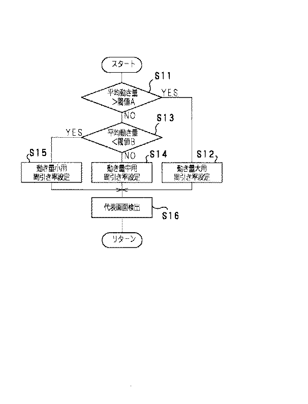
この特徴量を用いた第1の代表画面の検出処理の具体的な処理内容を、図7に示すフローチャートを用いて説明する。なお、この図7に示すフローチャートは、上述した図2の処理におけるステップS6の処理に対応する。
【0066】
システムコントローラ20は、図2に示すステップS1において、予め所定の閾値A及び閾値Bをデータベース21から読み込んでおく。これらの閾値は、映像信号の動き量から間引き率を設定する為の閾値であり、閾値Aは動き量の上限を示す閾値で、閾値Bは動き量の下限を示す閾値である。従って、閾値Aと閾値Bとの関係は、閾値A>閾値Bとなる。また、システムコントローラ20は、図2に示すステップS3において、特徴量として映像信号の動き量を特徴量検出回路17から読出しておく。なお、ここでの動き量は、各フレーム毎の動き量ではなく、例えば、30フレームや数10フレームといった一定時間における映像信号の平均動き量である。
【0067】
まず、ステップS11において、システムコントローラ20は、特徴量検出回路17から読みだした映像信号の平均動き量と閾値Aとを比較する。平均動き量が閾値Aよりも大きい場合は、ステップS12に進む。そして、ステップS12において、動き量が大きい場合の間引き率を設定し、すなわち、低間引き率に設定し、ステップS16に進む。また、ステップS11において、平均動き量が閾値Aよりも小さい場合は、ステップS13に進む。
【0068】
ステップS13において、システムコントローラ20は、特徴量検出回路17から読みだした映像信号の平均動き量と閾値Bとを比較する。平均動き量が閾値Bよりも小さい場合は、ステップS14に進む。そして、ステップS14おいて、動き量が中間の場合の間引き率を設定し、すなわち、中間引き率に設定し、ステップS16に進む。また、ステップS13において、平均動き量が閾値Bよりも小さい場合は、ステップS15に進む。そして、ステップS15において、動き量が大きい場合の間引き率を設定し、すなわち、高間引き率に設定し、ステップS16に進む。
【0069】
ステップS16において、システムコントローラ20は、代表画面検出処理を行う。すなわち、間引き制御信号を間引き処理回路18に供給する。なお、映像信号記録装置1では、システムコントローラ20が間欠間隔情報のみを間引き処理回路18に供給し、間引き処理回路18が独立に検出する代表画面を決定するように処理を行っても良いし、また、システムコントローラ20が検出する代表画面のフレーム位置を決定して検出制御信号を間引き処理回路18に供給し、間引き処理回路18がこの制御信号に基づき、各代表画面を検出するように処理をしても良い。
【0070】
ステップS16において、代表画面の検出処理が終了すると、システムコントローラ20は、処理を終了する。
【0071】
このように、映像信号記録装置1では、動き量に応じて間欠間隔を変えて代表画面を検出することによって、番組の動きの内容に適した映像信号の間欠記録ができ、記録した映像信号の内容を効率的に把握することができる。
【0072】
特徴量を用いた第2の代表画面の検出処理として、システムコントローラ20は、特徴量検出回路17の検出した映像のテロップ情報を用いた処理を行う。システムコントローラ20は、図8に示すように、放送される番組がテロップの出現頻度(以下、テロップの出現頻度を単に、テロップ量という。)の多い例えばニュース番組等の場合は高い間引き率で代表画面を検出し、スポーツ番組等の場合は、中間の間引き率で代表画面を検出し、また、ドラマや映画等の場合は、低い間引き率で代表画面を検出する。なお、各番組のテロップ量は、瞬間的なテロップ量を用いて判断をせず、一定時間内の平均的なテロップ量をもって判断をする。また、特徴量検出処理回路17による画面内のテロップの検出方法は、例えば、時間軸方向に連続して一定な輝度である画素を検出する方法や、近傍画素に比べて輝度レベルが高い領域を検出する方法や、画面内のエッジを検出しエッジパターンが所定の領域に連続しているものを検出する方法や、背景とのコントラストとを比較してそのヒストグラムを用いて検出する方法等が考えられるが、その方法は、特に限定されない。また、映像信号に付加されているテロップ量を用いて検出してもよい。
【0073】
この特徴量を用いた第2の代表画面の検出処理の具体的な処理内容を、図9に示すフローチャートを用いて説明する。なお、この図9に示すフローチャートは、上述した図2の処理におけるステップS6の処理に対応する。
【0074】
システムコントローラ20は、図2に示すステップS1において、予め所定の閾値C及び閾値Dをデータベース21から読み込んでおく。これらの閾値は、映像信号の間引き量を判断する為の閾値であり、閾値Cはテロップ量の上限を示す閾値で、閾値Dはテロップ量の下限を示す閾値である。従って、閾値Cと閾値Dとの関係は、閾値C>閾値Dとなる。また、システムコントローラ20は、図2に示すステップS3において、特徴量として映像信号のテロップ量を特徴量検出回路17から読出しておく。なお、ここでのテロップ量は、各フレーム毎のテロップ量ではなく、例えば、1分や数10分といった一定時間における映像信号の平均テロップ量である。
【0075】
まず、ステップS21において、システムコントローラ20は、特徴量検出回路17から読みだした映像信号の平均テロップ量と閾値Cとを比較する。平均テロップ量が閾値Cよりも大きい場合は、ステップS22に進む。そして、ステップS22おいて、テロップ量が大きい場合の間引き率を設定し、すなわち、高間引き率に設定し、ステップS26に進む。また、ステップS21において、平均テロップ量が閾値Cよりも小さい場合は、ステップS23に進む。
【0076】
ステップS23において、システムコントローラ20は、特徴量検出回路17から読みだした映像信号の平均テロップ量と閾値Dとを比較する。平均テロップ量が閾値Dよりも大きい場合は、ステップS24に進む。そして、ステップS24おいて、テロップ量が中間の場合の間引き率を設定し、すなわち、中間引き率に設定し、ステップS26に進む。また、ステップS23において、平均テロップ量が閾値Dよりも小さい場合は、ステップS25に進む。そして、ステップS25おいて、テロップ量が小さい場合の間引き率を設定し、すなわち、低間引き率に設定し、ステップS26に進む。
【0077】
ステップS26において、システムコントローラ20は、代表画面検出処理を行う。すなわち、間引き制御信号を間引き処理回路18に供給する。なお、映像信号記録装置1では、システムコントローラ20が間欠間隔情報のみを間引き処理回路18に供給し、間引き処理回路18が独立に検出する代表画面を決定するように処理を行っても良いし、また、システムコントローラ20が検出する代表画面のフレーム位置を決定して検出制御信号を間引き処理回路18に供給し、間引き処理回路18がこの制御信号に基づき、各代表画面を検出するように処理をしても良い。
【0078】
ステップS26において、代表画面の検出処理が終了すると、システムコントローラ20は、処理を終了する。
【0079】
このように、映像信号記録装置1では、テロップ量に応じて間欠間隔を変えて代表画面を検出することによって、番組のテロップの内容に適した映像信号の間欠記録ができ、記録した映像信号の内容を効率的に把握することができる。
【0080】
また、特徴量を用いた第3の代表画面の検出処理として、システムコントローラ20は、特徴量検出回路17の検出した映像の動き量を用いて、シーン(場面)の切り替わり点であるいわゆるカット点を検出する処理を行う。図10は、スポーツ番組(ここではサッカー番組)のシーンを用いて、この特徴量を用いた第3の代表画面の検出処理を具体的に示した図である。システムコントローラ20は、図10に示すように、時刻t1のキックシーンからボールシーンに切り替わった点の画面を代表画面として検出する。また、システムコントローラ20は、時刻t2のボールシーンからヘディングシーンに切り替わった点を代表画面として検出する。
【0081】
具体的に、システムコントローラ20は、このようなカット点の検出を行うため、検出した各画像間の動き量を所定の閾値と比較して、動き量がこの所定の閾値よりも大きくなったときに、代表画面を検出する処理を行う。
【0082】
このように、映像信号記録装置1では、映像信号のカット点を検出して、検出したカット点を代表画面とすることによって、映像の内容に適した映像信号の間欠記録ができ、記録した映像信号の内容を効率的に把握することができる。
【0083】
また、特徴量を用いた第4の代表画面の検出処理として、システムコントローラ20は、特徴量検出回路17の検出した映像の動き量を用いて、シーン(場面)の切り替わり点であるいわゆるカット点を代表画面として検出するとともに、シーンの切り替わりが少ない映像の部分では一定間隔ごと代表画面を検出する処理を行う。図11は、スポーツ番組(ここではサッカー番組)のシーンを用いて、この特徴量を用いた第4の代表画面の検出処理を具体的に示した図である。システムコントローラ20は、図11に示すように、時刻t4のキックシーンからボールシーンに切り替わった点の画面を代表画面として検出する。また、システムコントローラ20は、時刻t7のボールシーンからヘディングシーンに切り替わった点を代表画面として検出する。そして、システムコントローラ20は、このカット点を検出するとともに、時刻t3,時刻t5,時刻t6に示すように、所定の間隔で代表画面を検出する。
【0084】
具体的に、システムコントローラ20は、このような検出を行うため、検出した各画像間の動き量を所定の閾値と比較して、動き量がこの所定の閾値よりも大きくなったときに代表画面を検出する処理を行うとともに、この閾値を増減させて間引き率を変化させている。
【0085】
特徴量を用いた第4の代表画面の検出処理内容を図12に示すフローチャートを用いて説明する。なお、この図12に示すフローチャートは、上述した図2の処理におけるステップS6の処理に対応する。
【0086】
システムコントローラ20は、図2に示すステップS1において、予め所定の閾値Eをデータベース21から読み込んでおく。この閾値Eは、予め設定されている。また、システムコントローラ20は、図2に示すステップS3において、特徴量として映像信号の動き量を特徴量検出回路17から読に出しておく。なお、ここでの動き量は、例えば、1フレーム毎の動き量である。
【0087】
まず、ステップS31において、システムコントローラ20は、特徴量検出回路17から読み出した映像信号の動き量と閾値Eとを比較する。動き量が閾値Eよりも小さい場合は、ステップS32に進む。そして、ステップS32おいて、この閾値Eから所定の減算値を引いて処理を終了する。また、ステップS31において、動き量が閾値Eよりも大きい場合は、ステップS33に進む。
【0088】
ステップS33において、システムコントローラ20は、代表画面検出処理を行う。すなわち、間引き制御信号を間引き処理回路18に供給する。なお、システムコントローラ20は、検出する代表画面のフレーム位置を決定して検出制御信号を間引き処理回路18に供給し、間引き処理回路18がこの制御信号に基づき、各代表画面を検出するように処理をする。ステップS33で、代表画面の検出処理が終了すると、ステップS34に進む。
【0089】
ステップS34において、システムコントローラ20は、この閾値Eに所定の加算値を加えて処理を終了する。
【0090】
なお、オーディオ送信部10は、このステップS34の処理が終了すると、図2に示したステップS8の付加情報及び特徴量の更新があったかどうかを判断する処理に移ることになるが、この特徴量を用いた第4の代表画面の検出処理では、このステップS8の処理を行わず、ステップS9の動作が終了したかどうかを判断する。そして、動作が終了していなければ、ステップS3からの処理を繰り返す。
【0091】
ここで、ステップS32で閾値Eから一定量を引くために用いている定数である減算値と、ステップS34で閾値Eから一定量を加えるために用いている定数である加算値の関係について説明する。閾値Eは、上述したように動画像を構成する時間的に連続する各画面の動き量と比較をするための値である。このシステムコントローラ20では、動き量と閾値Eとの比較をして、この比較結果に応じて閾値Eを変化させるようになっている。すなわち、閾値Eの可変量は、代表画面を検出した場合に加算される加算値と、代表画面を検出しなかった場合に減算される減算値とにより決定される。この加算値と減算値の値により、入力される動画像に対する代表画面の検出量が決まる。例えば、加算値と減算値との比が1対100であれば、入力される動画像100枚に対し代表画面が1枚検出される。また、この閾値Eの可変量である加算値と減算値の絶対量が大きくなれば検出感度も大きく、平均的に代表画面が検出できる。さらに、可変量が小さければ差分の検出量に応じて代表画面の検出がばらつくことになる。
【0092】
このように、映像信号記録装置1では、映像信号のカット点を検出するとともにシーンの切り替わりが少ない場合には一定間隔毎に代表画面を検出することにより、映像の内容に適した映像信号の間欠記録ができ、記録した映像信号の内容を効率的に把握することができる。
【0093】
付加情報及び特徴量の両者を用いた場合の代表画面の検出処理
付加情報及び特徴量の両者を用いた第1の代表画面の検出処理として、システムコントローラ20は、付加情報検出回路16の検出したジャンル情報と特徴量検出回路17の検出した映像のテロップ情報を用いた処理を行う。システムコントローラ20は、図13(a)に示すように、テロップ画が多い例えばニュース番組等の場合は高間引き率であってテロップ画を優先して検出する代表画面の検出処理を行い、スポーツ番組等の場合は低い間引き率であってテロップ画を優先して検出する代表画面の検出処理を行い、また、ドラマや映画等の番組の場合は中間引き率であってテロップ画優先の代表画面の検出処理を行う。
【0094】
このテロップ画優先の代表画面検出とは、図13(b)に示すように、等間隔で代表画面を検出した後に、その検出した代表画面の近傍にテロップ画が存在するかどうかを判断し、近傍にテロップ画が存在する場合は、その画面を優先的に検出するものである。なお、この場合、システムコントローラ20は、テロップは、瞬間的なテロップ量を用いて判断をする必要がある。すなわち、システムコントローラ20は、各画面毎にテロップが存在するかどうかを特徴量検出回路17から取得する必要がある。
【0095】
この付加情報及び特徴量の両者を用いた第1の代表画面の検出処理の具体的な処理内容を、図14に示すフローチャートを用いて説明する。なお、この図14に示すフローチャートは、上述した図2の処理におけるステップS6の処理に対応する。
【0096】
システムコントローラ20は、図2に示すステップS3において、特徴量として映像信号のテロップ情報を特徴量検出回路17から読み出しておく。また、このステップS3において、付加情報としてジャンル情報を付加情報検出回路16から読み込んでおく。なお、ここでのテロップ情報は、各フレーム毎にテロップが存在するかどうかの情報である。
【0097】
まず、ステップS41において、システムコントローラ20は、付加情報検出回路16から読み出したテロップ情報に基づき、テロップが存在する各フレームに対しテロップフラグを立てる。
【0098】
続いてステップS42おいて、システムコントローラ20は、ジャンル情報を判定して、スポーツ番組であるかどうかを判断する。ステップS42でスポーツ番組であると判断すると、ステップS43おいて、低間引き率に設定し、ステップS47に進む。また、ステップS42において、スポーツ番組でないと判断すると、ステップS44に進む。
【0099】
ステップS44において、システムコントローラ20は、さらにジャンル情報を判定して、ニュース番組であるかどうかを判断する。ステップS44でニュース番組であると判断すると、ステップS45において、高間引き率に設定し、ステップS47に進む。また、ステップS44において、ニュース番組でないと判断すると、ステップS46において、中間引き率に設定し、ステップS47に進む。
【0100】
ステップS47において、システムコントローラ20は、代表画面検出処理を行う。すなわち、間引き制御信号を間引き処理回路18に供給する。
【0101】
続いてステップS48において、システムコントローラ20は、検出した代表画面の近傍にテロップフラグが存在するかどうかを判断する。近傍にテロップフラグが立ったフレームが存在すると判断する場合は、ステップS49に進み、上記ステップS47で設定した代表画面をテロップフラグが立っているフレームに変更し処理を終了する。また、近傍にテロップフラグが立ったフレームが存在しないと判断する場合は、そのまま処理を終了する。
【0102】
このように、映像信号記録装置1では、ジャンル情報とテロップ情報といった付加情報と特徴量を用いて代表画面を検出することにより、映像の内容に適した映像信号の間欠記録ができ、記録した映像信号の内容をさらに効率的に把握することができる。
【0103】
また、付加情報及び特徴量を用いた第2の代表画面の検出処理として、システムコントローラ20は、付加情報検出回路16の検出した放送時間帯の情報と特徴量検出回路17の検出した映像の動き量を用いた処理を行う。システムコントローラ20は、図15に示すように、放送される番組の時間帯がいわゆるゴールデンタイムといわれる時間帯である場合は上述した特徴量を用いた第4の代表画面の検出処理(以下、コマ取り代表画面検出処理という。)を用いて代表画面を検出し、 放送される番組の時間帯がゴールデンタイム以外の時間帯である場合は上述した特徴量を用いた第3の代表画面の検出処理(以下、カット点代表画面検出処理という。)を用いて代表画面を検出する。
【0104】
この付加情報及び特徴量の両者を用いた第2の代表画面の検出処理の具体的な処理内容を、図16に示すフローチャートを用いて説明する。なお、この図16に示すフローチャートは、上述した図2の処理におけるステップS6の処理に対応する。
【0105】
システムコントローラ20は、図2に示すステップS1において、予め所定の閾値をデータベース21から読み込んでおく。また、システムコントローラ20は、図2に示すステップS3において、特徴量として映像信号の動き量を特徴量検出回路17から読み出しておく。また、このステップS3において、付加情報として番組の放送時間帯の情報を付加情報検出回路16から読み込んでおく。
【0106】
ステップS51において、システムコントローラ20は、放送時間帯の情報に基づき、ゴールデンタイムの番組であるかどうかを判断する。ゴールデンタイムであると判断すると、ステップS52において、上述した図12のフローチャートに示すコマ取り検出処理を行い処理を終了する。
【0107】
また、ゴールデンタイムでないと判断すると、ステップS53において、所定の閾値と動き量を比較してカット点の検出を行い、このカット点を代表画面として検出する。
【0108】
なお、この付加情報及び特徴量を用いた第2の代表画面の検出処理として、放送時間帯によってカット点代表画面検出処理とコマ取り代表画面検出処理のいずれかに切り換える例を示したが、このカット点代表画面検出処理とコマ取り代表画面検出処理を切り換えることは放送時間帯によって切り換えるのみならず他の場合でも適用できる。例えば、1フレーム/5秒以上の間引き間隔の場合はコマ取り代表画面検出処理を行い、1フレーム/5秒以下の間引き間隔の場合はカット点代表画面検出処理を行うというように切り換えることもできる。
【0109】
このように、映像信号記録装置1では、付加情報及び特徴量を用いた複数の代表画面の検出処理を用いて、操作入力等に基づきこれらを必要に応じ選択して代表画面の検出を行うことにより、映像の内容に適した映像信号の間欠記録ができ、記録した映像信号の内容をさらに効率的に把握することができる。
【0110】
以上のように、映像信号記録装置1では、付加情報、特徴量を用いて映像信号の間欠記録を行うことにより、記録した映像の概略を容易に把握することができる。さらに、映像の内容に応じて効率的に代表画面を選択するため、短時間で記録した映像の概略がつかめる有効な間欠画像を生成することができる。
【0111】
つぎに、映像信号記録装置1のデータベース21を用いた学習処理について説明する。
【0112】
システムコントローラ20は、上述した付加情報や特徴量の情報、及び、ユーザが操作入力処理回路22を用いて入力した付加情報等の情報をある一定期間の間データベース21上に保存しておき、その情報に基づき統計処理等を行い、間引き率の設定をする。
【0113】
例えば、データベース21には、図17に示すように、放送時間帯の各間引き率の度数分布のテーブルを有している。システムコントローラ20は、操作入力の指定等がない場合は、この度数分布を参照して、一番高い度数の間引き率を選択して、代表画面を検出する。
【0114】
この学習処理を用いた検出処理の具体的な処理内容を、図18に示すフローチャートを用いて説明する。なお、この図18に示すフローチャートは、上述した図2の処理におけるステップS4の処理に対応する。
【0115】
システムコントローラ20は、図2に示すステップS1において、上述した過去の間引き率の度数分布をデータベース21から読み込んでおく。また、システムコントローラ20は、図2に示すステップS3において、付加情報を付加情報検出回路16から読み出し、また、特徴量を特徴量検出回路17から読み出しておく。
【0116】
まず、ステップS61において、システムコントローラ20は、ユーザからの間引き率の設定又は各間引き率の設定処理方法の指定があるかどうかを判断する。ユーザからの指定が有る場合は、ステップS62に進み、システムコントローラ20は、操作入力に基づき、間引き率の指定を行う。すなわち、このステップS62から上述した具体的な間引き率の設定処理を行い、代表画面を検出する。また、ステップS61でユーザからの指定がない場合は、ステップS63に進む。
【0117】
ステップS63において、システムコントローラ20は、データベース21上に間引き率の情報を示した度数分布のデータがあるかどうかを判断する。システムコントローラ20は、データベース21上に度数分布のデータが無いと判断した場合はステップS64に進み、このステップS64において、間引き率を初期値例えば中間引き率に設定して処理を終了する。また、データベース21上に度数分布のデータがあると判断した場合はステップS65に進む。
【0118】
ステップS65において、システムコントローラ20は、予め読み込んだ付加情報等をデータベース21上の度数分布に加える。
【0119】
続いてステップS66において、システムコントローラ20は統計処理を行い、この統計処理に基づきステップS67において、間引き率の設定をする。
【0120】
以上のように、映像信号記録装置1では、一定期間の間引き率をデータベース21に記憶させ、このデータベース21に記憶する情報に基づき、間引き率の設定を行うことにより、好適な間引き率の設定をすることができる。
【0121】
つぎに、映像信号記録装置1のシステムコントローラ20から記録処理回路14に供給する識別信号について説明する。
【0122】
システムコントローラ20は、上述したように間引き率や検出する代表画面を求め、この間引き率等に基づき間引き処理回路18を制御する。さらに、システムコントローラ20は、間引き率等に応じて識別信号を記録処理回路14に供給する。記録処理回路14は、この識別信号を映像信号のサブコードやIDコードとして、この映像信号とともに記録する。
【0123】
例えば、光ディスクに映像信号を記録するのであれば、下記の表1に示すように、記録最小単位であるセクタ毎にサブコードを記録する。そして、再生の際には、このサブコードに基づき間欠的な映像信号の再生を行う。
【0124】
【表1】
以上のように映像信号記録装置1では、識別信号を映像信号に付加することにより、通常の映像信号を記録媒体15に記録するとともに、この映像信号に間欠再生情報を記録することができる。すなわち、記録媒体15上に、通常の映像信号と間欠映像信号を2種類記録することなくなり、記録媒体15を効率的に利用することができる。従って、映像信号記録装置1では、再生した際に間欠的に再生することができ、且つ、通常の再生もすることができる映像信号を記録することができる。
【0126】
【発明の効果】
本発明に係る映像信号記録装置では、付加情報及び特徴量を選択的に用いて代表画面を検出して間欠的な映像信号を記録することにより、記録した内容の概略を知ることができる間欠画像を生成でき、この間欠画像を再生することにより、付加情報及び特徴量の内容に応じた映像信号を効率的に把握することができる。
【0127】
本発明に係る映像信号記録装置では、特徴量に応じて代表画面を検出して間欠的な映像信号を記録することにより、記録した内容の概略を把握することができる間欠映像を生成することができ、この間欠映像を再生することにより、特徴量の内容に応じた映像信号を効率的に把握することができる。
【0129】
本発明に係る映像信号記録方法では、付加情報及び特徴量を選択的に用いて代表画面を検出して間欠的な映像信号を記録することにより、記録した内容の概略を知ることができる間欠画像を生成でき、この間欠画像を再生することにより、付加情報及び特徴量の内容に応じた映像信号を効率的に把握することができる。
【0130】
本発明に係る映像信号記録方法では、特徴量に応じて代表画面を検出して間欠的な映像信号を記録することにより、記録した内容の概略を把握することができる間欠映像を生成することができ、この間欠映像を再生することにより、特徴量の内容に応じた映像信号を効率的に把握することができる。
【図面の簡単な説明】
【図1】本発明を適用した実施の形態の映像信号記録装置のブロック構成図である。
【図2】上記映像信号記録装置のシステムコントローラの処理内容を示すフローチャートである。
【図3】上記映像信号記録装置が検出する代表画面の間引き率を説明する図である。
【図4】上記映像信号記録装置が検出する代表画面の間引き率を説明する図である。
【図5】上記映像信号記録装置が検出する代表画面の間引き率を説明する図である。
【図6】上記映像信号記録装置が検出する代表画面の間引き率を説明する図である。
【図7】上記映像信号記録装置のシステムコントローラの処理内容を示すフローチャートである。
【図8】上記映像信号記録装置が検出する代表画面の間引き率を説明する図である。
【図9】上記映像信号記録装置のシステムコントローラの処理内容を示すフローチャートである。
【図10】上記映像信号記録装置が検出する代表画面を説明する図である。
【図11】上記映像信号記録装置が検出する代表画面を説明する図である。
【図12】上記映像信号記録装置のシステムコントローラの処理内容を示すフローチャートである。
【図13】上記映像信号記録装置が検出する代表画面を説明する図である。
【図14】上記映像信号記録装置のシステムコントローラの処理内容を示すフローチャートである。
【図15】上記映像信号記録装置が検出する代表画面の間引き率を説明する図である。
【図16】上記映像信号記録装置のシステムコントローラの処理内容を示すフローチャートである。
【図17】上記映像信号記録装置のデータベース21が記憶する間引き率の度数分布を説明する図である。
【図18】上記映像信号記録装置のシステムコントローラの処理内容を示すフローチャートである。
【符号の説明】
1 映像信号記録装置、2 映像信号入力処理回路、3 カメラ信号入力処理回路、4 デジタル映像信号入力処理回路、5 受信信号入力処理回路、7 映像信号圧縮回路、14 記録処理回路、15 記録媒体、16、付加情報検出回路、17 特徴量検出回路、18 間引き処理回路、20 システムコントローラ、21 データベース、22 操作入力処理回路[0001]
BACKGROUND OF THE INVENTION
The present invention relates to a video signal recording apparatus and video signal recording method for recording video signals such as television broadcasting and digital satellite broadcasting, and in particular, video for recording intermittent video for grasping the outline of the content of the video signal to be recorded. The present invention relates to a signal recording apparatus and a video signal recording method.
[0002]
[Prior art]
In recent years, recording media such as optical disks, hard disks, and digital video tapes that record video signals broadcast on television broadcasts and digital satellite broadcasts have storage capacities ranging from several megabytes to several tens of gigabytes. Progressing. Therefore, such a large-capacity recording medium enables continuous recording for a long time, such as several hours to several tens of hours, for television broadcasting or the like.
[0003]
[Problems to be solved by the invention]
By the way, when recording such as television broadcasting using such a recording medium, since the recording capacity is very large, it is possible to confirm all contents in a short time even if high-speed playback or the like is performed after recording. Can not. Therefore, when recording a television broadcast or the like using such a large-capacity recording medium, it is necessary to have a function for confirming the outline of the recorded contents and the recording position information of each program.
[0004]
However, it has been very difficult to confirm an outline of the contents of a video signal recorded on a conventional recording medium. For example, in order to confirm the outline of the content recorded on the recording medium, an interval playback in which playback points are skipped at regular intervals can be considered. In this interval playback, the information content of the recorded video signal is completely unrelated. It will be played back and the contents will be difficult to understand.
[0005]
The present invention has been made in view of such circumstances, and when a broadcast video signal is recorded on a recording medium, a video signal recording that generates an intermittent video that can grasp an outline of the recorded content. An object is to provide an apparatus and a video signal recording method.
[0006]
[Means for Solving the Problems]
In order to solve the above-described problem, a video signal recording apparatus according to the present invention includesProjectionDetection means for reproducing a moving image from an image signal and intermittently detecting a representative screen from the reproduced moving image;RecordingAdditional information reproducing means for reproducing additional information of an image signal;Feature quantity detection means for detecting the feature quantity of the video signal;The above additional information andSelectively using featuresControl means for controlling the intermittent interval of the representative screen detected by the detecting means, and recording the representative screen on a recording mediumTo controlRecordcontrolMeans.
[0007]
In this video signal recording apparatus, additional informationAnd selectively using featuresA representative screen is detected and intermittent video signals are recorded.
[0008]
The video signal recording apparatus according to the present invention isProjectionDetection means for reproducing a moving image from an image signal and intermittently detecting a representative screen from the reproduced moving image;RecordingA feature amount detecting unit that detects a feature amount of an image signal; a feature amount that is detected by the feature amount detecting unit and includes an average value of a motion amount or telop amount of an image for a certain period; and an upper limit value of the motion amount or telop amount And a control means for controlling the intermittent rate of the representative image detected by the detection means by controlling the thinning rate of the moving image based on the lower limit value, and the representative screen is recorded on a recording medium.To controlRecordcontrolMeans.
[0009]
In this video signal recording apparatus, a representative screen is detected according to the feature amount and an intermittent video signal is recorded.
[0011]
In this video signal recording apparatus, a representative screen is detected in accordance with the additional information and the feature amount, and an intermittent video signal is recorded.
[0012]
A video signal recording method according to the present invention includes:ProjectionPlay video from the image signal andRecordingReproduce additional information of the image signal,Detect the feature quantity of the broadcast video signal,Additional information aboveAnd selectively using featuresThe intermittent interval of the representative screen to be detected is changed, the representative screen is intermittently detected from the reproduced moving image, and the representative screen is recorded on the recording medium.To controlIt is characterized by that.
[0013]
In this video signal recording method, additional informationAnd selectively using featuresA representative screen is detected and intermittent video signals are recorded.
[0014]
A video signal recording method according to the present invention includes:ProjectionPlay video from the image signal andRecordingA feature amount including an average value of the motion amount or telop amount of the image signal for a certain period is detected, and the moving image thinning rate is determined based on the feature amount and the upper limit value and the lower limit value of the motion amount or telop amount. To change the intermittent interval of the representative screen to be detected, detect the representative screen intermittently from the reproduced video,
Record the representative screen on a recording mediumTo controlIt is characterized by that.
[0015]
In this video signal recording method, an intermittent video signal is recorded by detecting a representative screen according to the feature amount.
[0017]
In this video signal recording method, an intermittent video signal is recorded by detecting a representative screen according to the additional information and the feature amount.
[0018]
DETAILED DESCRIPTION OF THE INVENTION
A video signal recording apparatus according to an embodiment of the present invention will be described below with reference to the drawings. The video signal recording apparatus according to this embodiment records a broadcast or transmitted video signal on a recording medium, detects a representative screen of the video signal, and generates an intermittent video obtained by thinning video signals other than the representative screen. It is a device to do.
[0019]
FIG. 1 is a block diagram of a video signal recording apparatus according to an embodiment of the present invention.
[0020]
The video
[0021]
The video
[0022]
In addition, the video
[0023]
Also, additional
[0024]
In addition, the video
[0025]
For example, an analog video signal broadcast by wire or a transmitted analog video signal is input to the video signal input processing circuit 2. The video signal input processing circuit 2 demodulates and converts the analog video signal into a baseband video signal, converts the baseband video signal into a digital video signal, and supplies the digital video signal to the video
[0026]
For example, a video signal photographed by a video camera is input to the camera signal
[0027]
For example, a digitally transmitted video signal or a digitally broadcast video signal is input to the digital video signal
[0028]
The received signal
[0029]
Digital video signals from the video signal input processing circuit 2, the camera signal
[0030]
The video
[0031]
For example, an audio signal detected by a microphone is input to the microphone signal input processing circuit 9. If the audio signal from the microphone is an analog signal, the microphone signal input processing circuit 9 demodulates and converts it into a baseband audio signal, converts the baseband audio signal into a digital audio signal, and converts the audio signal into a digital audio signal. The signal is supplied to the
[0032]
For example, a digitally transmitted audio signal or a digitally broadcast audio signal is input to the digital audio signal input processing circuit 10. The digital audio signal input processing circuit 10 performs processing such as demodulation of the input audio signal, converts it to baseband digital data, performs error correction, decompression processing of the compressed signal, etc., and switches the audio signal Supply to the
[0033]
Digital audio signals from the audio signal input processing circuit 8, the microphone signal input processing circuit 9, the digital audio signal input processing circuit 10, and the reception signal
[0034]
A digital audio signal from the audio
[0035]
A digital audio signal from the audio signal
[0036]
The
[0037]
The additional
[0038]
A digital video signal from the video
[0039]
A digital video signal from the video
[0040]
The
[0041]
Further, the
[0042]
Further, the
[0043]
The
[0044]
Further, the operation input information from the operation
[0045]
Next, the above-described representative screen detection control performed by the
[0046]
FIG. 2 is a flowchart showing the contents of the representative screen detection control performed by the
[0047]
In step S <b> 2, the
[0048]
In step S <b> 3, the
[0049]
In step S4, the
[0050]
In step S5, the
[0051]
In step S6, the
[0052]
In step S7, an identification signal is generated, and this identification signal is supplied to the
[0053]
In step S8, the
[0054]
In step S9, the
[0055]
Next, specific examples of the additional information and the feature amount described above will be given, and specific contents of the representative screen detection process using them will be described.
[0056]
Representative screen detection process when additional information is used
Examples of the additional information detected by the additional
[0057]
As the first representative screen detection process using the additional information, the
[0058]
As described above, the video
[0059]
Further, as the second representative screen detection process using the additional information, the
[0060]
As described above, the video
[0061]
Further, as the third representative screen detection process using the additional information, the
[0062]
Thus, the video
[0063]
Representative screen detection processing using feature values
The feature amount detected by the feature
[0064]
As the first representative screen detection process using the feature amount, the
[0065]
The specific processing contents of the first representative screen detection processing using this feature amount will be described with reference to the flowchart shown in FIG. The flowchart shown in FIG. 7 corresponds to the process of step S6 in the process of FIG.
[0066]
The
[0067]
First, in step S <b> 11, the
[0068]
In step S <b> 13, the
[0069]
In step S16, the
[0070]
In step S16, when the representative screen detection process ends, the
[0071]
As described above, the video
[0072]
As detection processing of the second representative screen using the feature amount, the
[0073]
The specific processing contents of the second representative screen detection processing using this feature amount will be described with reference to the flowchart shown in FIG. The flowchart shown in FIG. 9 corresponds to the process of step S6 in the process of FIG.
[0074]
The
[0075]
First, in step S <b> 21, the
[0076]
In step S <b> 23, the
[0077]
In step S26, the
[0078]
In step S26, when the representative screen detection process ends, the
[0079]
As described above, the video
[0080]
In addition, as the third representative screen detection process using the feature amount, the
[0081]
Specifically, the
[0082]
As described above, the video
[0083]
Further, as the fourth representative screen detection process using the feature amount, the
[0084]
Specifically, in order to perform such detection, the
[0085]
The contents of the fourth representative screen detection process using the feature amount will be described with reference to the flowchart shown in FIG. The flowchart shown in FIG. 12 corresponds to the process of step S6 in the process of FIG.
[0086]
The
[0087]
First, in step S <b> 31, the
[0088]
In step S33, the
[0089]
In step S34, the
[0090]
When the process of step S34 is completed, the audio transmitting unit 10 proceeds to a process of determining whether the additional information and the feature amount have been updated in step S8 illustrated in FIG. In the fourth representative screen detection process used, the process of step S8 is not performed, and it is determined whether the operation of step S9 is completed. If the operation has not ended, the processing from step S3 is repeated.
[0091]
Here, the relationship between the subtraction value that is a constant used for subtracting a certain amount from the threshold value E in step S32 and the addition value that is a constant used to add a certain amount from the threshold value E in step S34 will be described. . The threshold value E is a value for comparison with the amount of movement of each temporally continuous screen constituting the moving image as described above. The
[0092]
As described above, the video
[0093]
Representative screen detection processing using both additional information and feature values
As the first representative screen detection process using both the additional information and the feature amount, the
[0094]
This telop image priority representative screen detection, as shown in FIG. 13B, determines whether a telop image exists in the vicinity of the detected representative screen after detecting the representative screen at equal intervals. When a telop image exists in the vicinity, the screen is preferentially detected. In this case, the
[0095]
The specific processing content of the first representative screen detection processing using both the additional information and the feature amount will be described with reference to the flowchart shown in FIG. Note that the flowchart shown in FIG. 14 corresponds to the process of step S6 in the process of FIG. 2 described above.
[0096]
In step S3 shown in FIG. 2, the
[0097]
First, in step S41, the
[0098]
Subsequently, in step S42, the
[0099]
In step S44, the
[0100]
In step S47, the
[0101]
Subsequently, in step S48, the
[0102]
As described above, the video
[0103]
In addition, as the second representative screen detection process using the additional information and the feature amount, the
[0104]
The specific processing contents of the second representative screen detection processing using both the additional information and the feature amount will be described with reference to the flowchart shown in FIG. Note that the flowchart shown in FIG. 16 corresponds to the process of step S6 in the process of FIG. 2 described above.
[0105]
The
[0106]
In step S51, the
[0107]
If it is determined that it is not the golden time, a cut point is detected by comparing a predetermined threshold value with the amount of movement in step S53, and this cut point is detected as a representative screen.
[0108]
In addition, as the second representative screen detection process using the additional information and the feature amount, an example of switching to either the cut point representative screen detection process or the frame-removal representative screen detection process according to the broadcast time zone has been shown. Switching between the cut point representative screen detection process and the frame picking representative screen detection process can be applied not only in accordance with the broadcast time zone but also in other cases. For example, it is possible to switch such that a frame-removal representative screen detection process is performed in the case of a thinning interval of 1 frame / 5 seconds or more, and a cut-point representative screen detection process is performed in the case of a thinning interval of 1 frame / 5 seconds or less. .
[0109]
As described above, the video
[0110]
As described above, the video
[0111]
Next, a learning process using the
[0112]
The
[0113]
For example, as shown in FIG. 17, the
[0114]
Specific processing contents of the detection processing using this learning processing will be described with reference to the flowchart shown in FIG. Note that the flowchart shown in FIG. 18 corresponds to the process of step S4 in the process of FIG. 2 described above.
[0115]
In step S <b> 1 shown in FIG. 2, the
[0116]
First, in step S61, the
[0117]
In step S <b> 63, the
[0118]
In step S <b> 65, the
[0119]
Subsequently, in step S66, the
[0120]
As described above, in the video
[0121]
Next, an identification signal supplied from the
[0122]
The
[0123]
For example, if a video signal is recorded on an optical disc, a subcode is recorded for each sector, which is the minimum recording unit, as shown in Table 1 below. In reproduction, intermittent video signals are reproduced based on the subcode.
[0124]
[Table 1]
As described above, in the video
[0126]
【The invention's effect】
In the video signal recording apparatus according to the present invention, the additional informationAnd selectively using featuresBy detecting a representative screen and recording an intermittent video signal, an intermittent image can be generated so that the outline of the recorded content can be known. By reproducing this intermittent image, additional information can be obtained.And featuresIt is possible to efficiently grasp the video signal corresponding to the video signal.
[0127]
The video signal recording apparatus according to the present invention can generate an intermittent video that can grasp the outline of the recorded content by detecting a representative screen according to the feature amount and recording an intermittent video signal. In addition, by reproducing this intermittent video, it is possible to efficiently grasp a video signal corresponding to the content of the feature amount.
[0129]
In the video signal recording method according to the present invention, the additional informationAnd selectively using featuresBy detecting a representative screen and recording an intermittent video signal, an intermittent image can be generated so that the outline of the recorded content can be known. By reproducing this intermittent image, additional information andFeature valueIt is possible to efficiently grasp the video signal corresponding to the content of the video.
[0130]
In the video signal recording method according to the present invention, an intermittent video that can grasp an outline of the recorded content can be generated by detecting a representative screen according to the feature amount and recording an intermittent video signal. In addition, by reproducing this intermittent video, it is possible to efficiently grasp a video signal corresponding to the content of the feature amount.
[Brief description of the drawings]
FIG. 1 is a block diagram of a video signal recording apparatus according to an embodiment to which the present invention is applied.
FIG. 2 is a flowchart showing processing contents of a system controller of the video signal recording apparatus.
FIG. 3 is a diagram for explaining a thinning rate of a representative screen detected by the video signal recording apparatus.
FIG. 4 is a diagram for explaining a thinning rate of a representative screen detected by the video signal recording apparatus.
FIG. 5 is a diagram for explaining a thinning rate of a representative screen detected by the video signal recording apparatus.
FIG. 6 is a diagram for explaining a thinning rate of a representative screen detected by the video signal recording apparatus.
FIG. 7 is a flowchart showing processing contents of a system controller of the video signal recording apparatus.
FIG. 8 is a diagram for explaining a thinning rate of a representative screen detected by the video signal recording apparatus.
FIG. 9 is a flowchart showing processing contents of a system controller of the video signal recording apparatus.
FIG. 10 is a diagram illustrating a representative screen detected by the video signal recording apparatus.
FIG. 11 is a diagram illustrating a representative screen detected by the video signal recording apparatus.
FIG. 12 is a flowchart showing processing contents of a system controller of the video signal recording apparatus.
FIG. 13 is a diagram illustrating a representative screen detected by the video signal recording apparatus.
FIG. 14 is a flowchart showing processing contents of a system controller of the video signal recording apparatus.
FIG. 15 is a diagram for explaining a thinning rate of a representative screen detected by the video signal recording apparatus.
FIG. 16 is a flowchart showing processing contents of a system controller of the video signal recording apparatus.
FIG. 17 is a diagram for explaining a frequency distribution of thinning rates stored in the
FIG. 18 is a flowchart showing the processing contents of the system controller of the video signal recording apparatus.
[Explanation of symbols]
DESCRIPTION OF
Claims (14)
上記映像信号の付加情報を再生する付加情報再生手段と、
上記映像信号の特徴量を検出する特徴量検出手段と、
上記付加情報及び特徴量を選択的に用いて上記検出手段により検出する代表画面の間欠間隔を制御する制御手段と、
上記代表画面を記録媒体に記録するように制御する記録制御手段と
を備える映像信号記録装置。Playing a moving picture Film image signal, detecting means for detecting the intermittent representative screen from the moving image reproduction,
An additional information reproducing means for reproducing the additional information above Kiutsu image signal,
Feature quantity detection means for detecting the feature quantity of the video signal;
Control means for controlling the intermittent interval of the representative screen detected by the detection means by selectively using the additional information and the feature amount ;
A video signal recording apparatus comprising: a recording control unit configured to control the representative screen to be recorded on a recording medium.
を特徴とする請求項1に記載の映像信号記録装置。The recording control means may movies image signal, a video signal recording apparatus according to claim 1, wherein the controller controls to record into the recording medium a video signal of the representative screen.
上記記録制御手段は、映像信号に上記識別信号を付加して、この映像信号を記録媒体に記録するように制御すること
を特徴とする請求項1に記載の映像信号記録装置。An identification signal generating means for generating an identification signal indicating a portion included representatives screens of movies image signal,
It said recording control means, the movies image signal by adding the identification signal, a video signal recording apparatus according to claim 1, wherein the controller controls so as to record the video signal on a recording medium.
を特徴とする請求項1に記載の映像信号記録装置。It said control means, a video signal recording apparatus according to claim 1, characterized in that to control the intermittent spacing of representative pictures detected by the detection means in accordance with the contents of the movies image signal.
を特徴とする請求項1に記載の映像信号記録装置。It said control means, a video signal recording apparatus according to claim 1, characterized in that to control the intermittent spacing of representative pictures detected by the detection means in accordance with the broadcast time of the movies image signal.
を特徴とする請求項1に記載の映像信号記録装置。Said control means, a video signal recording apparatus according to claim 1, in accordance with the supplier's Film image signal and controlling the intermittent spacing of representative pictures detected by the detection means.
上記映像信号の特徴量を検出する特徴量検出手段と、
上記特徴量検出手段により検出され、一定期間の画像の動き量又はテロップ量の平均値を含む特徴量と、動き量又はテロップ量の上限値及び下限値とに基づいて、上記動画像の間引き率を制御して、上記検出手段により検出する代表画像の間欠間隔を制御する制御手段と、
上記代表画面を記録媒体に記録するように制御する記録制御手段と
を備える映像信号記録装置。Playing a moving picture Film image signal, detecting means for detecting the intermittent representative screen from the moving image reproduction,
A characteristic quantity detecting means for detecting a feature quantity of the upper Kiutsu image signal,
Based on the feature amount detected by the feature amount detection means and including the average value of the motion amount or telop amount of the image for a certain period, and the upper limit value and lower limit value of the motion amount or telop amount, the moving image thinning rate Control means for controlling the intermittent interval of the representative image detected by the detection means,
A video signal recording apparatus comprising: a recording control unit configured to control the representative screen to be recorded on a recording medium.
を特徴とする請求項7に記載の映像信号記録装置。The recording control means may movies image signal, a video signal recording apparatus according to claim 7, wherein the controller controls to record into the recording medium a video signal of the representative screen.
上記記録制御手段は、映像信号に上記識別信号を付加して、この映像信号を記録媒体に記録するように制御すること
を特徴とする請求項7に記載の映像信号記録装置。An identification signal generating means for generating an identification signal indicating a portion included representatives screens of movies image signal,
It said recording control means, the movies image signal by adding the identification signal, a video signal recording apparatus according to claim 7, wherein the controller controls so as to record the video signal on a recording medium.
上記制御手段は、上記動き量に応じて上記検出手段により検出する代表画面の間欠間隔を制御すること
を特徴とする請求項7に記載の映像信号記録装置。The characteristic quantity detecting means detects the motion amount of movies image signal,
The video signal recording apparatus according to claim 7, wherein the control unit controls an intermittent interval of the representative screen detected by the detection unit in accordance with the amount of movement.
上記制御手段は、上記テロップ信号に応じて上記検出手段により検出する代表画面の間欠間隔を制御すること
を特徴とする請求項7に記載の映像信号記録装置。It said feature detection means detects a telop signal of movies image signal,
The video signal recording apparatus according to claim 7, wherein the control unit controls an intermittent interval of the representative screen detected by the detection unit in accordance with the telop signal.
上記制御手段は、上記場面変化点に応じて上記検出手段により検出する代表画面の間欠間隔を制御すること
を特徴とする請求項7に記載の映像信号記録装置。The characteristic quantity detecting means detects a scene change point of movies image signal,
The video signal recording apparatus according to claim 7, wherein the control unit controls an intermittent interval of the representative screen detected by the detection unit according to the scene change point.
上記映像信号の付加情報を再生し、
上記放送された映像信号の特徴量を検出し、
上記付加情報及び特徴量を選択的に用いて検出する代表画面の間欠間隔を変化させ、再生した動画像から間欠的に代表画面を検出し、
上記代表画面を記録媒体に記録するように制御すること
を特徴とする映像信号記録方法。Playing a moving picture Film image signal,
It reproduces the additional information above Kiutsu image signal,
Detect the feature quantity of the broadcast video signal,
The intermittent interval of the representative screen to be detected by selectively using the additional information and the feature amount is changed, and the representative screen is intermittently detected from the reproduced moving image.
A video signal recording method comprising: controlling the representative screen to be recorded on a recording medium.
上記映像信号の一定期間の画像の動き量又はテロップ量の平均値を含む特徴量を検出し、
上記特徴量と動き量又はテロップ量の上限値及び下限値とに基づいて、上記動画像の間引き率を制御して、検出する代表画面の間欠間隔を変化させ、再生した動画像から間欠的に代表画面を検出し、
上記代表画面を記録媒体に記録するように制御すること
を特徴とする映像信号記録方法。Playing a moving picture Film image signal,
Detecting a feature quantity including a mean value of motion amount or a telop of a certain period of the image of the upper Kiutsu image signal,
Based on the feature value and the upper limit value and the lower limit value of the motion amount or the telop amount, the moving image thinning rate is controlled to change the intermittent interval of the representative screen to be detected, and intermittently from the reproduced moving image. Detect representative screen,
A video signal recording method comprising: controlling the representative screen to be recorded on a recording medium.
Priority Applications (1)
| Application Number | Priority Date | Filing Date | Title |
|---|---|---|---|
| JP13561397A JP4000623B2 (en) | 1997-05-26 | 1997-05-26 | Video signal recording apparatus and video signal recording method |
Applications Claiming Priority (1)
| Application Number | Priority Date | Filing Date | Title |
|---|---|---|---|
| JP13561397A JP4000623B2 (en) | 1997-05-26 | 1997-05-26 | Video signal recording apparatus and video signal recording method |
Publications (2)
| Publication Number | Publication Date |
|---|---|
| JPH10326480A JPH10326480A (en) | 1998-12-08 |
| JP4000623B2 true JP4000623B2 (en) | 2007-10-31 |
Family
ID=15155910
Family Applications (1)
| Application Number | Title | Priority Date | Filing Date |
|---|---|---|---|
| JP13561397A Expired - Fee Related JP4000623B2 (en) | 1997-05-26 | 1997-05-26 | Video signal recording apparatus and video signal recording method |
Country Status (1)
| Country | Link |
|---|---|
| JP (1) | JP4000623B2 (en) |
Cited By (1)
| Publication number | Priority date | Publication date | Assignee | Title |
|---|---|---|---|---|
| KR101749420B1 (en) | 2015-10-20 | 2017-06-20 | 주식회사 에스비에스 | Apparatus and method for extracting representation image of video contents using closed caption |
Families Citing this family (4)
| Publication number | Priority date | Publication date | Assignee | Title |
|---|---|---|---|---|
| JP4165851B2 (en) | 2000-06-07 | 2008-10-15 | キヤノン株式会社 | Recording apparatus and recording control method |
| US6882793B1 (en) | 2000-06-16 | 2005-04-19 | Yesvideo, Inc. | Video processing system |
| US7110458B2 (en) * | 2001-04-27 | 2006-09-19 | Mitsubishi Electric Research Laboratories, Inc. | Method for summarizing a video using motion descriptors |
| JP4525558B2 (en) | 2005-11-08 | 2010-08-18 | ソニー株式会社 | Information processing apparatus, imaging apparatus, information processing method, and computer program |
-
1997
- 1997-05-26 JP JP13561397A patent/JP4000623B2/en not_active Expired - Fee Related
Cited By (1)
| Publication number | Priority date | Publication date | Assignee | Title |
|---|---|---|---|---|
| KR101749420B1 (en) | 2015-10-20 | 2017-06-20 | 주식회사 에스비에스 | Apparatus and method for extracting representation image of video contents using closed caption |
Also Published As
| Publication number | Publication date |
|---|---|
| JPH10326480A (en) | 1998-12-08 |
Similar Documents
| Publication | Publication Date | Title |
|---|---|---|
| JP4026100B2 (en) | Information processing apparatus and method, and recording medium | |
| US5949953A (en) | Disk media, and method of and device for recording and playing back information on or from a disk media | |
| US8358910B2 (en) | Video signal recording apparatus, video signal reproducing apparatus and video signal recording and reproducing apparatus | |
| JP4178629B2 (en) | Information processing apparatus and method, and recording medium | |
| US20030229894A1 (en) | Method and apparatus for processing images, method and apparatus for recording and reproducing images, and television receiver utilizing the same | |
| JP3701051B2 (en) | Information recording apparatus and information reproducing apparatus | |
| US7502544B2 (en) | Recording and reproduction apparatus | |
| JPH10224724A (en) | Television signal recorder, its method, television signal reproducing device and its method, and television signal recording and reproducing device and recording medium | |
| JP4029487B2 (en) | Recording apparatus and recording method, reproducing apparatus and reproducing method, and recording medium | |
| US7801420B2 (en) | Video image recording and reproducing apparatus and video image recording and reproducing method | |
| JP3988205B2 (en) | Video signal recording / reproducing apparatus, video signal recording / reproducing method, video signal reproducing apparatus, and video signal reproducing method | |
| US7305171B2 (en) | Apparatus for recording and/or reproducing digital data, such as audio/video (A/V) data, and control method thereof | |
| JP2004072727A (en) | Image processing method, image processing apparatus, image recording and reproducing apparatus, and television receiver | |
| JP2007053510A (en) | Recording/reproducing device, reproducing device, and method and program for adjusting volume automatically | |
| WO2006078365A1 (en) | Method and apparatus for skipping commercials | |
| JP4000623B2 (en) | Video signal recording apparatus and video signal recording method | |
| JP4474748B2 (en) | Signal processing apparatus and method, video signal recording apparatus, and video signal reproducing apparatus | |
| US7209639B2 (en) | Recording apparatus and recording method | |
| JPH08275101A (en) | Apparatus and method for speed-variable search for recorded picture | |
| JP3807225B2 (en) | Compressed video signal recording device | |
| JPH09284704A (en) | Video signal selecting device and digest recording device | |
| JP4675885B2 (en) | Information recording apparatus, information recording method, and information recording program | |
| US8027562B2 (en) | Method and apparatus for recording images, method and apparatus for recording and reproducing images, and television receiver utilizing the same | |
| KR100978995B1 (en) | Information recording device, information reproduction device, method, and computer program | |
| JP2000069414A (en) | Recorder, recording method, reproduction device, reproduction method and cm detection method |
Legal Events
| Date | Code | Title | Description |
|---|---|---|---|
| A977 | Report on retrieval |
Free format text: JAPANESE INTERMEDIATE CODE: A971007 Effective date: 20070129 |
|
| A131 | Notification of reasons for refusal |
Free format text: JAPANESE INTERMEDIATE CODE: A131 Effective date: 20070206 |
|
| A521 | Written amendment |
Free format text: JAPANESE INTERMEDIATE CODE: A523 Effective date: 20070409 |
|
| TRDD | Decision of grant or rejection written | ||
| A01 | Written decision to grant a patent or to grant a registration (utility model) |
Free format text: JAPANESE INTERMEDIATE CODE: A01 Effective date: 20070724 |
|
| A61 | First payment of annual fees (during grant procedure) |
Free format text: JAPANESE INTERMEDIATE CODE: A61 Effective date: 20070806 |
|
| FPAY | Renewal fee payment (event date is renewal date of database) |
Free format text: PAYMENT UNTIL: 20100824 Year of fee payment: 3 |
|
| FPAY | Renewal fee payment (event date is renewal date of database) |
Free format text: PAYMENT UNTIL: 20100824 Year of fee payment: 3 |
|
| LAPS | Cancellation because of no payment of annual fees |