JP3998552B2 - Water meter protective cover - Google Patents
Water meter protective cover Download PDFInfo
- Publication number
- JP3998552B2 JP3998552B2 JP2002285662A JP2002285662A JP3998552B2 JP 3998552 B2 JP3998552 B2 JP 3998552B2 JP 2002285662 A JP2002285662 A JP 2002285662A JP 2002285662 A JP2002285662 A JP 2002285662A JP 3998552 B2 JP3998552 B2 JP 3998552B2
- Authority
- JP
- Japan
- Prior art keywords
- cover
- meter
- fitting
- water
- water meter
- Prior art date
- Legal status (The legal status is an assumption and is not a legal conclusion. Google has not performed a legal analysis and makes no representation as to the accuracy of the status listed.)
- Expired - Fee Related
Links
Images


Landscapes
- Measuring Volume Flow (AREA)
Description
【0001】
【産業上の利用分野】
本発明は、集合住宅など設置環境から設置スペースや配管方向等が制約されている場所に水道用メーターを設置する場合に用いる水道用メーターの配管連結リリースに締着支持されたメーターを保温したり、衝撃から防護したりするために用いる水道用メーター保護カバーに関するものである。
【0002】
【従来の技術】
配管連結リリースに締着支持されたメーターは、例えば集合住宅の階段の踊り場の側壁部に設けられるパイプシャフト等に設置されるため、埋設等による保護環境を整えることができず発泡ポリエチレン等による特別な保温カバーが用いられてきている。
【0003】
従来、この種の保温カバーは、特許文献1に示されるようにリリースの長手方向に沿って分割されたカバー片によって、メーター本体、止水栓、逆止弁を含めてユニット全体に左右から覆着されるようになっていた。
【0004】
【特許文献1】
特開2002−88827号公報
【0005】
【発明が解決しようとする課題】
しかしながら、従来の保温カバーは被着物をユニット形態でグローバルに包み込むものの、被着物の形状が複雑なため被着物とカバーが完全にフィットすることがなく、カバーの形状も複雑なものとなり、メーターのユニット形態やリリース形状が異なるごとにカバーの形状も異なってくるため汎用性に欠けるという問題もあった。
【0006】
また、複雑な形状の被着物に対する被着作業も面倒であり、分割されたカバー片の着合も分割面同志を面着合して接合部側面を面状ファスナーで止める方式によっており、安定した被着状態を維持することが困難な一面を有していた。
【0007】
更に、分割されたカバー片の着合が面着合であるため、カバー片の着合位置合わせの問題があり、仮止め等を行ってズレを無くしてから面状ファスナーで本固定するといった手順も必要であった。
【0008】
【課題を解決するための手段】
本発明は上記した問題に対応しようとするものであり、カバー片をリリースに締着支持されたメーターの底部とリリースベースの間隙部を挿通してメーターの底部に覆着する底部覆着部を張出形成した側当て盤と、底部覆着部先端の嵌合凸部を嵌入する嵌合凹部を形成した側当て盤とから成る底部覆着カバー、メーター本体に上部から覆着する本体覆着カバー及び本体覆着カバー上面に形成した嵌合凹部に嵌合する覆蓋カバーに分割し、カバー片同志の嵌合構造により嵌着により覆着するように構成した。
【0009】
すなわち、メーター底部の覆着について、メーター底部とリリースベースの間隙部を挿通する底部覆着部を側当て盤に張出形成し、この側当て盤と対峙して対をなす側当て盤に底部覆着部先端に形成した嵌合凸部を嵌入する嵌合凹部を形成し、底部覆着部を間隙部に挿通し嵌合凸部を嵌合凹部に嵌入して凹凸嵌合することによって底部覆着カバーがメーター底部への覆着と同時に構成されるようにしたものである。
【0010】
また、本体覆着カバーを水道用メーター本体の上部から覆着する筒枠状に構成し、面接合による覆着の不安定が生じないようにした。
【0011】
更に、覆蓋カバーも本体覆着カバー上面に形成した嵌合凹部に嵌合する嵌合構造に構成し、カバー全体が嵌合によって一体に形成されるようにしてカバー片を順次嵌合していくことによってメーターへの覆着が当然に行われるようにしたものである。
【0012】
また更に、被着時等にリリースホルダーやメーター本体の一次側と二次側を確認できるように、メーターの水流方向を示す矢印を底部覆着部上面とカバー本体の外側面に表示するように構成した。
【0013】
【実施例】
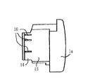
以下、本発明の実施例を図面を参照して説明する。1は配管連結リリースBに締着支持された水道用メーターAの底部に覆着する底部覆着カバーで、内側に水道用メーターの底側一側の曲面に沿った凹曲面11、12をそれぞれ形成した一対の側当て盤1aと1bから成っている。
【0014】
側当て盤1aの内側下側部には、リリースBに締着支持されたメーターAの底部とリリースベースbの間隙部を挿通してメーターの底部に覆着する底部覆着部13が張出形成されており、その先端に、側当て盤1aと対をなして対向する側当て盤1bの内側下側部に形成された嵌合凹部15に嵌入する嵌合凸部14が形成されている。
【0015】
嵌合凸部14の底面には嵌入方向に平行する凸条16、16・・が形成され、対向側当て盤1bの嵌入凹部15の対応位置に形成した凹条(図示しない)と嵌合するようになっており、側当て盤1aと1bの嵌合構成を確実強固なものとしている。なお、この凸条16と凹条は必ずしも設ける必要はなく、カバーの素材として発泡ポリエチレン等の弾性素材が用いられる場合には凸条16のみを設け、挿入先端から嵌入方向に向けてテーパー状に厚みを増すように構成して嵌入締着度を高めることもできる。
【0016】
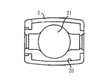
2は本体覆着カバーで、下側部にリリースに締着支持された水道用メーターの上面側の側部曲面と検針表示部aの形状に沿った凹曲面により覆着スペース21が形成され、上側部には覆蓋カバー3と嵌合する嵌合凹部22が形成され、下端部は底部覆着カバー1の上面に形成された嵌入枠17と嵌合する嵌合部23となっている。
【0017】
覆蓋カバー3は内側下側面に本体覆着カバー2の嵌合凹部22に嵌入する嵌合枠31が形成され、嵌合によってカバー上面を覆蓋するようになっている。なお、底部覆着カバー1の上面嵌入枠17と本体覆着カバー2の下側嵌合部23、本体覆着カバー2の上側嵌合凹部22と覆蓋カバー3の下側嵌合枠31の凹凸嵌合は、それぞれ、テーパー面による嵌合とすることにより嵌合締着度を高めることができる。
【0018】
また、底部覆着カバー1の外側にはメーターの水流方向を示す矢印の下半分M2、本体覆着カバー2の外側には上半分M1が描かれ、両カバーの嵌合により矢印の表示Mが行われるように構成されると共に、底部覆着部13の上面にも矢印の表示が行われてメーターへの覆着時、覆着後のリリースホルダーやメーター本体の一次側と二次側が確認できるように構成されている。
【0019】
以上のように構成した保護カバーは、先ず、配管連結リリースBに締着支持された水道用メーターAの一側部に側当て盤1bの凹曲面12を当接し、他側部からメーターAの底部とリリースベースbの間隙部Cに側当て盤1aの底部覆着部13を挿通して、その先端嵌合凸部14を側当て盤1bの嵌合凹部15に嵌入してメーターAを挟んで嵌合することにより、側当て盤1a、1bは密着嵌合して固定具なしに一体固定化する。
【0020】
次いで、メーターAの上部から本体覆着カバー2を覆着し、底部覆着カバー1の上面嵌入枠17と本体覆着カバー2の下側嵌合部23を嵌合し、更に、覆蓋カバー3を本体覆着カバー2の上部に載置して本体覆着カバー2の上側嵌合凹部22と覆蓋カバー3の下側嵌合枠31を嵌合して水道用メーターAを配管連結リリースBに締着支持された状態のままでカバーするものである。
【0021】
本発明は以上のように構成したので、水道用メーターAをリリースBに締着支持された状態のままで、カバー片を当接して順次嵌合していくことによって、水道用メーターAを収納したカバー全体が嵌合によって一体に形成され、メーターへの覆着が当然に行われるもので、面状ファスナーのような固定材を必要とすることなく安定したカバーを行うことができるたものである。
【0022】
【図面の簡単な説明】
【図1】 本発明の実施例を示すもので、カバー片と被着メーターとの関係を分解配置状態としてカバー片各部材の要部を断面として示した水道用メーター及びリリースと保護カバーの全体正面図
【図2】 同じく、カバー片と被着メーターとの関係を分解配置状態としてカバー片各部材を示した水道用メーターと保護カバーの全体側面図
【図3】 同じく、覆着カバーを断面として示した覆着完了状態における水道用メーター及びリリースと保護カバーの全体側面図
【図4】 同じく、底部覆着カバーの嵌合関係を示す側当て盤を分解対峙させた状態における平面図
【図5】 同じく、底部覆着カバーの底部覆着部に、嵌入方向に平行する凸条を形成した実施例を示す底部覆着部を張出形成した側当て盤の底面図
【図6】 同じく、本体覆着カバーの平面図
【図7】 同じく、本体覆着カバーの縦断側面図
【図8】 同じく、本体覆着カバーの底面図
【図9】 同じく、覆蓋カバーの底面図
【符号の説明】
1 底部覆着カバー
1a 底部覆着カバーの凸側側当て盤
1b 底部覆着カバーの凹側側当て盤
11 底部覆着カバーの凹曲面
12 底部覆着カバーの凹曲面
13 底部覆着部
14 底部覆着カバーの嵌合凸部
15 底部覆着カバーの嵌合凹部
16 嵌合凸部底面の嵌入方向に平行する凸条
17 底部覆着カバーの上面嵌入枠
2 本体覆着カバー
21 本体覆着カバーの覆着スペース
22 本体覆着カバーの嵌合凹部
23 本体覆着カバーの下端嵌合部
3 覆蓋カバー
31 覆蓋カバーの下側嵌合枠
A 水道用メーター
B 配管連結リリース
C メーターの底部とリリースベースとの間隙部
a メーターの検針表示部
b リリースベース
M メーターの水流方向を示す矢印
M1 矢印の上半分
M2 矢印の下半分[0001]
[Industrial application fields]
The present invention keeps the meter fastened and supported by the pipe connection release of the water meter used when installing the water meter in a place where the installation space or piping direction is restricted from the installation environment such as an apartment house. The present invention relates to a water meter protective cover used to protect against impacts.
[0002]
[Prior art]
The meter fastened and supported by the pipe connection release, for example, is installed on the pipe shaft etc. provided on the side wall of the stairway of the housing complex, so it cannot provide a protective environment due to burial etc. Warm insulation covers have been used.
[0003]
Conventionally, this type of heat insulation cover is covered with the cover unit divided along the longitudinal direction of the release as shown in Patent Document 1 from the left and right sides of the entire unit including the meter body, the stop cock, and the check valve. It was supposed to be worn.
[0004]
[Patent Document 1]
Japanese Patent Laid-Open No. 2002-88827
[Problems to be solved by the invention]
However, the conventional heat insulation cover wraps the adherend globally in the form of a unit, but the shape of the adherend is complicated, so the adherend and the cover do not fit perfectly, and the shape of the cover becomes complicated. There is also a problem that the shape of the cover is different every time the unit form and the release shape are different, so that it is not versatile.
[0006]
In addition, the adherence work to the adherend of complicated shape is also troublesome, and the joining of the divided cover pieces is also based on the method of joining the divided surfaces together and fastening the side surface of the joint part with a surface fastener, which is stable. It was difficult to maintain the adhesion state.
[0007]
Furthermore, since the joining of the divided cover pieces is surface joining, there is a problem of the joining position of the cover pieces, and the temporary fixing or the like is performed to eliminate the shift, and then the main fixing with the surface fastener. Was also necessary.
[0008]
[Means for Solving the Problems]
The present invention is intended to address the above-described problem, and includes a bottom cover portion that covers the bottom portion of the meter through the gap between the bottom portion of the meter and the release base that is supported by fastening the cover piece to the release. A bottom covering cover comprising a side pad that is formed in an overhang and a side pad that is formed with a fitting recess for fitting the fitting convex part at the tip of the bottom covering part, and a body covering that covers the meter body from the top The cover and the main body cover cover were divided into cover covers that fit into the fitting recesses formed on the upper surface of the cover, and the cover pieces were covered by fitting with a cover structure.
[0009]
That is, for the covering of the bottom of the meter, a bottom covering portion that extends through the gap between the bottom of the meter and the release base is formed on the side padding plate, and the bottom portion of the side padding plate that is opposed to this side padding plate A bottom part is formed by forming a fitting concave part into which the fitting convex part formed at the tip of the covering part is fitted, inserting the bottom covering part into the gap part, and fitting the convex part into the fitting concave part and fitting the concave and convex parts. The covering cover is constructed at the same time as covering the bottom of the meter.
[0010]
In addition, the main body covering cover is formed in a cylindrical frame shape covering from the upper part of the water meter main body so that the instability of the covering due to surface bonding does not occur.
[0011]
Furthermore, the cover cover is also configured to be fitted into a fitting recess formed on the upper surface of the body cover cover, and the cover pieces are sequentially fitted so that the entire cover is integrally formed by fitting. By doing so, the meter is naturally covered.
[0012]
Furthermore, the arrow indicating the water flow direction of the meter is displayed on the upper surface of the bottom cover part and the outer surface of the cover body so that the primary side and the secondary side of the release holder and the meter body can be confirmed when being attached. Configured.
[0013]
【Example】
Embodiments of the present invention will be described below with reference to the drawings. Reference numeral 1 denotes a bottom cover covering the bottom of the water meter A that is fastened and supported by the pipe connection release B. On the inside, concave
[0014]
A
[0015]
Formed on the bottom surface of the
[0016]
2 is a body covering cover, and a
[0017]
The
[0018]
In addition, the lower half M2 of the arrow indicating the water flow direction of the meter is drawn on the outside of the bottom covering cover 1, and the upper half M1 is drawn on the outer side of the main
[0019]
The protective cover configured as described above first contacts the concave
[0020]
Next, the main
[0021]
Since the present invention is configured as described above, the water meter A is accommodated by sequentially contacting the cover pieces while the water meter A is being fastened and supported by the release B. The entire cover is integrally formed by fitting, and is naturally covered with a meter, so that a stable cover can be performed without the need for a fixing material such as a surface fastener. is there.
[0022]
[Brief description of the drawings]
FIG. 1 shows an embodiment of the present invention, in which the relationship between a cover piece and a deposition meter is disassembled and the main part of each member of the cover piece is shown in cross section, and the entire release and protective cover Front view [Figure 2] Similarly, a side view of the water meter and protective cover showing the cover piece components in an exploded state of the relationship between the cover piece and the deposition meter [Figure 3] Similarly, the cross section of the covering cover Overall side view of water meter and release and protective cover in cover completed state shown as [Fig. 4] Similarly, a plan view in a state where the side paddle showing the fitting relationship of the bottom cover cover is disassembled and confronted [Fig. 5] Similarly, a bottom view of the side cover plate in which the bottom cover portion is formed so as to project from the bottom cover portion of the bottom cover cover, and the bottom cover portion is formed so as to extend in the fitting direction. Body cover Plan view 7 Similarly, vertical sectional side view of the body Kutsugaechaku cover [8] Similarly, a bottom view of the body Kutsugaechaku cover 9 likewise, bottom view of the covering cover EXPLANATION OF REFERENCE NUMERALS
DESCRIPTION OF SYMBOLS 1 Bottom part cover 1a Bottom part cover cover convex side pad 1b Bottom part cover cover
C Gaps between the bottom of the meter and the release base a Meter reading display part b Release base M Arrow indicating the water flow direction of the meter M1 Upper half of the arrow M2 Lower half of the arrow
Claims (3)
Priority Applications (1)
| Application Number | Priority Date | Filing Date | Title |
|---|---|---|---|
| JP2002285662A JP3998552B2 (en) | 2002-09-30 | 2002-09-30 | Water meter protective cover |
Applications Claiming Priority (1)
| Application Number | Priority Date | Filing Date | Title |
|---|---|---|---|
| JP2002285662A JP3998552B2 (en) | 2002-09-30 | 2002-09-30 | Water meter protective cover |
Publications (2)
| Publication Number | Publication Date |
|---|---|
| JP2004124371A JP2004124371A (en) | 2004-04-22 |
| JP3998552B2 true JP3998552B2 (en) | 2007-10-31 |
Family
ID=32278904
Family Applications (1)
| Application Number | Title | Priority Date | Filing Date |
|---|---|---|---|
| JP2002285662A Expired - Fee Related JP3998552B2 (en) | 2002-09-30 | 2002-09-30 | Water meter protective cover |
Country Status (1)
| Country | Link |
|---|---|
| JP (1) | JP3998552B2 (en) |
Families Citing this family (6)
| Publication number | Priority date | Publication date | Assignee | Title |
|---|---|---|---|---|
| JP4566571B2 (en) * | 2004-02-03 | 2010-10-20 | 株式会社キッツ | Thermal insulation cover for meter unit |
| DE102014202853A1 (en) * | 2014-02-17 | 2015-08-20 | Robert Bosch Gmbh | Sensor arrangement for determining at least one parameter of a fluid flowing through a channel |
| CN104634408B (en) * | 2015-02-02 | 2017-08-25 | 长春市自来水公司水表厂 | Easy-to-dismount automatic water gauge outfit |
| CN105675037A (en) * | 2015-12-31 | 2016-06-15 | 门得赛特(天津)科技有限公司 | Reading instrument counting mechanism anti-dismounting device |
| JP7121525B2 (en) * | 2018-04-26 | 2022-08-18 | 前澤給装工業株式会社 | Meter unit positioning and fixing method and fixing mechanism member used therefor |
| JP7850552B2 (en) * | 2021-12-20 | 2026-04-23 | 前澤給装工業株式会社 | Protective cover for smart meters |
-
2002
- 2002-09-30 JP JP2002285662A patent/JP3998552B2/en not_active Expired - Fee Related
Also Published As
| Publication number | Publication date |
|---|---|
| JP2004124371A (en) | 2004-04-22 |
Similar Documents
| Publication | Publication Date | Title |
|---|---|---|
| JP3604893B2 (en) | Seal holder, seal assembly, and sealing method | |
| CN100464107C (en) | Clamp type pipe joint | |
| JP3998552B2 (en) | Water meter protective cover | |
| JP2007500324A (en) | Pipe joint device using flange | |
| JP4313303B2 (en) | Compression unit | |
| CN104748342B (en) | The body structure of air-treatment unit | |
| JP5156675B2 (en) | Gas stove | |
| JP4744740B2 (en) | Housing type pipe fitting | |
| CN223826287U (en) | Wall hanging stove panel and wall hanging stove | |
| JPS6328382Y2 (en) | ||
| JP2587977B2 (en) | Fluid pipe piping method, fluid pipe terminal fixing device and terminal fixing joint used therefor | |
| CN218441152U (en) | Pipe joint internal and external sealing device | |
| JP3498443B2 (en) | Toilet seat unit | |
| CN223348887U (en) | Cabinet and electrical equipment | |
| EP1382924A1 (en) | Sealing device particularly for doors of refrigerators, freezers and the like | |
| JPH093997A (en) | Faucet mounting device | |
| JPH061958Y2 (en) | Frame material for panel | |
| JPH0828770A (en) | Fall-off preventive cover for tube connecting clip | |
| JP4807540B2 (en) | Burner part attaching device and structure of burner part attaching device | |
| JP2020012538A (en) | Saddle band | |
| JP2018193694A (en) | Wall panel coupling structure and wall panel coupling method | |
| JP4598447B2 (en) | Parting edge | |
| JPH10107454A (en) | Seal structure of housing joint | |
| JP2009002372A (en) | Insulation material placement tool and piping material protection cover | |
| CN208748916U (en) | A kind of bathroom wallboard installing structure |
Legal Events
| Date | Code | Title | Description |
|---|---|---|---|
| A621 | Written request for application examination |
Free format text: JAPANESE INTERMEDIATE CODE: A621 Effective date: 20040804 |
|
| A977 | Report on retrieval |
Free format text: JAPANESE INTERMEDIATE CODE: A971007 Effective date: 20060908 |
|
| A131 | Notification of reasons for refusal |
Free format text: JAPANESE INTERMEDIATE CODE: A131 Effective date: 20061002 |
|
| A521 | Request for written amendment filed |
Free format text: JAPANESE INTERMEDIATE CODE: A523 Effective date: 20061107 |
|
| A131 | Notification of reasons for refusal |
Free format text: JAPANESE INTERMEDIATE CODE: A131 Effective date: 20070507 |
|
| A521 | Request for written amendment filed |
Free format text: JAPANESE INTERMEDIATE CODE: A523 Effective date: 20070604 |
|
| TRDD | Decision of grant or rejection written | ||
| A01 | Written decision to grant a patent or to grant a registration (utility model) |
Free format text: JAPANESE INTERMEDIATE CODE: A01 Effective date: 20070724 |
|
| A61 | First payment of annual fees (during grant procedure) |
Free format text: JAPANESE INTERMEDIATE CODE: A61 Effective date: 20070807 |
|
| R150 | Certificate of patent or registration of utility model |
Ref document number: 3998552 Country of ref document: JP Free format text: JAPANESE INTERMEDIATE CODE: R150 Free format text: JAPANESE INTERMEDIATE CODE: R150 |
|
| FPAY | Renewal fee payment (event date is renewal date of database) |
Free format text: PAYMENT UNTIL: 20100817 Year of fee payment: 3 |
|
| FPAY | Renewal fee payment (event date is renewal date of database) |
Free format text: PAYMENT UNTIL: 20100817 Year of fee payment: 3 |
|
| FPAY | Renewal fee payment (event date is renewal date of database) |
Free format text: PAYMENT UNTIL: 20110817 Year of fee payment: 4 |
|
| R250 | Receipt of annual fees |
Free format text: JAPANESE INTERMEDIATE CODE: R250 |
|
| FPAY | Renewal fee payment (event date is renewal date of database) |
Free format text: PAYMENT UNTIL: 20120817 Year of fee payment: 5 |
|
| R250 | Receipt of annual fees |
Free format text: JAPANESE INTERMEDIATE CODE: R250 |
|
| FPAY | Renewal fee payment (event date is renewal date of database) |
Free format text: PAYMENT UNTIL: 20130817 Year of fee payment: 6 |
|
| R250 | Receipt of annual fees |
Free format text: JAPANESE INTERMEDIATE CODE: R250 |
|
| R250 | Receipt of annual fees |
Free format text: JAPANESE INTERMEDIATE CODE: R250 |
|
| R250 | Receipt of annual fees |
Free format text: JAPANESE INTERMEDIATE CODE: R250 |
|
| R250 | Receipt of annual fees |
Free format text: JAPANESE INTERMEDIATE CODE: R250 |
|
| R250 | Receipt of annual fees |
Free format text: JAPANESE INTERMEDIATE CODE: R250 |
|
| R250 | Receipt of annual fees |
Free format text: JAPANESE INTERMEDIATE CODE: R250 |
|
| R250 | Receipt of annual fees |
Free format text: JAPANESE INTERMEDIATE CODE: R250 |
|
| R250 | Receipt of annual fees |
Free format text: JAPANESE INTERMEDIATE CODE: R250 |
|
| R250 | Receipt of annual fees |
Free format text: JAPANESE INTERMEDIATE CODE: R250 |
|
| R250 | Receipt of annual fees |
Free format text: JAPANESE INTERMEDIATE CODE: R250 |
|
| LAPS | Cancellation because of no payment of annual fees |