JP3996998B2 - Disc holder - Google Patents
Disc holder Download PDFInfo
- Publication number
- JP3996998B2 JP3996998B2 JP09020898A JP9020898A JP3996998B2 JP 3996998 B2 JP3996998 B2 JP 3996998B2 JP 09020898 A JP09020898 A JP 09020898A JP 9020898 A JP9020898 A JP 9020898A JP 3996998 B2 JP3996998 B2 JP 3996998B2
- Authority
- JP
- Japan
- Prior art keywords
- edge
- cover
- folded piece
- disc
- notch
- Prior art date
- Legal status (The legal status is an assumption and is not a legal conclusion. Google has not performed a legal analysis and makes no representation as to the accuracy of the status listed.)
- Expired - Fee Related
Links
Images


Description
【0001】
【発明の属する技術分野】
本発明は、矩形のディスク、円形ディスク、又は、ディスク用ケース(以下、「収納品」という。)」を経済的且つ確実に収納することができるディスク用ホルダに関する。本発明は、特に、電子媒体としてミニディスクに代表されるディスクをそのまま収納するのに適している。
【0002】
【従来の技術】
従来のディスク用ホルダとして、特開昭61−127475号公報に記載されるように、二重の折畳みカバーを2つ折りに成形し、折畳みカバーの見開き一方に切り欠き溝を形成して、ディスクを切り欠き溝で支持するものがある。そして、このディスク用ホルダは、二重の折畳みカバーの間に一方の側縁開口から物品を収容することができるようになっている。
【0003】
【発明が解決しようとする課題】
上記ディスク用ホルダでは、ディスクの横方向移動が拘束されていないので、ホルダ内にディスクを保持しておくことが確実でなく、運送中や持運び中にディスクがホルダから落下する危険がある。電子媒体のような精密機器では、落下によって機能が破壊されことがあるので、ディスク用ホルダ内で確実に保持しておく必要がある。
また、ディスクが外部に露出しないように、二重の折畳みカバーの見開き面に切り欠き溝を形成しているため、ディスクを切り欠き溝に挿入する際、溝を大きく開かねばらならず、ディスクを装着することが極めて面倒である。
さらに、側縁開口から物品を取り出す方向と、ディスクを取り出す方向が同じであるため、例えば、収納物を取り出す際にディスクが落下する危険もある。
【0004】
本発明の主たる目的は、上記収納品の移動を拘束して確実に保持収納するとともに、衝撃等からも収納品を保護するディスク用ホルダを提供することである。
【0005】
【課題を解決するための手段】
本発明は、のど部で折り曲げ可能な表表紙及び裏表紙と、前記表表紙及び裏表紙の一方の1つの縁部に連設され、該縁部に隣合う他の縁部に被着されて前記表表紙及び裏表紙の一方との間で袋体を形成する折り返し片とを有し、被着された折り返し片が、該折り返し片の自由縁部に対向して収納品に当接する横動拘束当接縁と、前記横動拘束当接縁に当接した前記収納品に当接するように離間対峙させた縦動拘束当接縁とを形成した切り込みを有し、前記自由縁部に前記収納品の少なくとも一部を覆う折り返しカバーが連設されており、前記折り返しカバーを閉じたとき、前記収納品が、前記横動拘束当接縁と縦動拘束当接縁と折り返しカバーとにより保持されるディスク用ホルダにより、前記課題を解決したものである。
【0006】
【作用】
本発明によるディスク用ホルダでは、まず、表紙を開いた状態にする。折り返し片は、表表紙又は裏表紙に設けられており、
表紙の見開き一面において袋体を形成している。
取扱説明書やパンフレットの紙葉は、この袋体に収納できるようになっている。
また、折り返し片には、切り込みが形成されており、袋体は、紙葉を収納することに加えて切り込みによってディスク等の収納品を保持するようになっている。
すなわち、切り込みは、横動拘束当接縁と縦動拘束当接縁を有し、自由縁部に臨む横動拘束当接縁に収納品を当接させるとともに、縦動拘束当接縁に収納品を当接させることにより、その収納品は3方向への移動を拘束される。
折り返し片は、さらに、自由縁部において折り返しカバーを有し、切り込みに装着された収納品を覆うように折り返しカバーを折り返すと、収納品は4方向への移動を拘束される。
表紙を閉じた状態において、折り返しカバーは裏返ることがなく、ディスク用ホルダの持運び中、収納品は、ディスク用ホルダ内に確実に保持される。
【0007】
また、本発明では、折り返し片により袋体を形成する場合、その折り返し片を表表紙又は裏表紙の下縁に連設し、表表紙又は裏表紙の側縁に被着しておくことが好ましい。
こうすることにより、紙葉を抜き差しする方向が表紙の上下方向となり、収納品を抜き差しする方向が表紙の左右方向となる。それぞれの物品を抜き差しする方向を異なせることによって、一方の物品を取り出す際に、他方の物品がディスク用ホルダ内から脱落しにくくなる。
また、折り返し片を表表紙又は裏表紙の縦方向長さより短くして、上縁とのど部に向って開放させておくことが好ましい。そして、短くなった上縁に隣接して切り込みを形成しておくことが好ましい。
こうすることにより、折り返し片の上縁を持ち上げて、その折り返し片を歪めることにより、切り込みに収納品を容易に装着することができる。
【0008】
【実施例】
以下、図面を参照して本発明によるディスク用ホルダの実施例を説明する。
収納品の例として矩形ディスクを例示したが、本発明は、円形ディスクやそのケースにも応用することができる。
図1乃至図3は、本発明の理解を助けるための参考例となるディスク用ホルダを示し、図1は、参考例となるディスク用ホルダの展開図であり、図2は、完成した参考例となるディスク用ホルダの斜視図であり、図3はディスクを収納したディスク用ホルダの斜視図である。
そして、図4乃至図6は、本発明によるディスク用ホルダの実施例を示し、図4は、ディスク用ホルダの展開図であり、図5は、完成したディスク用ホルダの斜視図であり、図6は、ディスクを収納したディスク用ホルダの斜視図である。
【0009】
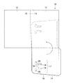
まず、本発明の理解を助けるための参考例となるディスク用ホルダ10は、図1に示すように、展開した状態において、実質的に、同じ形状の表表紙11と裏表紙12とがのど部13によって折り返し可能になっており、裏表紙12の下縁に折り返し片14が連設されたものである。
そして、このディスク用ホルダ10は、紙又はプラスチックシート等の薄いシートを打ち抜き加工して成形される。なお、折筋15は、肉厚のディスクが収納されたとき、表表紙11に皺が生じないようにマチを作るためのものである。
【0010】
折り返し片14は、裏表紙12の下縁を折筋として裏表紙12に重なるように折り返され、裏表紙12の側縁に糊付けされる。
そして、折り返し片14は、裏表紙12より僅かに幅が狭く、裏表紙12より縦方向寸法が短い。裏表紙12に被着された折り返し片14は、上縁及びのど部13側の側縁を自由縁部16として袋体を形成する。この袋体には、取扱説明書やパンフレット等の紙葉が挟み込まれる。
【0011】
また、前記折り返し片14には、ディスク装着用の切り込み17が形成されている。
そして、この切り込み17は、裏表紙12縦方向中央でディスクを保持でき、裏表紙12ののど部13近くでディスクを保持できる位置に形成されている。また、この切り込み17は、折り返し片14の上縁に隣接している。
さらに、前記切り込み17は、ハ字状の一対の切り抜き部18により構成されており、裏表紙12の側縁側の横動拘束当接縁19と、裏表紙12の上縁側及び下縁側の縦動拘束当接縁20を有している。横動拘束当接縁19は、のど部13からディスクの一辺より僅かに離れた位置に設けられている。縦動拘束当接縁20は、前記一辺に隣合う両辺の対向間隔で対峙離間している。
【0012】
上記のように構成された本発明の参考例であるディスク用ホルダ10は、折り返し片14の上縁近傍に切り込み17が設けられており、その切り込み17は、容易に変形させられる。
そして、切り込み17は、ディスクを受け入れるように開口する。のど部13方向からディスクをその切り込み17に挿入すると、そのディスクは、横動拘束当接縁19に当接するとともに、縦動拘束当接縁20に挟持される。
ディスクの前記一辺に対向する一辺は、のど部13近くで、そののど部13に沿って位置決めされる。表紙を閉じると、ディスクは、4方向で移動を拘束される。
【0013】
従って、持運び中や輸送中にディスク用ホルダ内から脱落することがなく、ディスクは、表紙内に確実に保持される。
本参考例のディスク用ホルダ10は、積み重ねにも便利である。すなわち、ディスクを保持する切り込み17が表紙の縦方向中央に設けられているので、ディスク用ホルダを積層させたときに厚みのばらつきが少なく、荷崩れが生じることも少ない。
また、紙葉とディスクの挿入方向を直交させて異ならせたことにより、一方の物品を抜き差しする際、他方の物品が飛び出したり落下したりすることもなく、物品の取扱も容易である。
【0014】
そこで、本発明の実施例であるディスク用ホルダ10’について、以下に説明する。
本発明の実施例であるディスク用ホルダ10’は、図4に示すように、展開した状態において、実質的に、同じ形状の表表紙11’と裏表紙12’とが、のど部13’によって折り返し可能になっており、裏表紙12’の下縁に折り返し片14’が連設されたものである。
本発明の実施例においても、ディスク用ホルダ10’は、紙又はプラスチックシート等の薄いシートを打ち抜き加工して成形されている。
【0015】
折り返し片14’は、裏表紙12’の下縁を折筋として裏表紙12’に重なるように折り返され、裏表紙12’の側縁に糊付けされている。
折り返し片14’は、裏表紙12’下縁ののど部13’近傍から側縁に傾斜する自由縁部16’を有し、その幅が漸減している。
また、折り返し片14’は、裏表紙12’より縦方向寸法が短い。裏表紙12’に被着された折り返し片14’は、上縁及びのど部13’側の側縁を自由縁部16’として袋体を形成している。
したがって、この袋体には、取扱説明書やパンフレット等の紙葉が挟み込まれる。
【0016】
前記折り返し片14’には、ディスク装着用の切り込み17’が形成されている。
前記切り込み17’は、裏表紙12’縦方向中央でディスクを保持でき、折り返し片14’の自由縁部16’でディスクを保持できる位置に形成されている。
また、この切り込み17’は、折り返し片14’の上縁にも隣接している。
そして、切り込み17’は、ハ字状の一対の切り抜き部18’により構成されており、裏表紙12’の側縁側の横動拘束当接縁19’と、裏表紙12’の上縁側及び下縁側の縦動拘束当接縁20’を有している。
さらに、横動拘束当接縁19’は、のど部13’側の自由縁部16’からディスクの一辺より僅かに離れた位置に設けられている。
縦動拘束当接縁20’は、前記一辺に隣合う両辺の対向間隔で対峙離間している。
【0017】
本発明の実施例は、さらに、折り返し片14’に折り返しカバー21が一体に形成されている。
そして、この折り返しカバー21は、切り込み17’と横方向で整列して形成されており、折り返し片14’ののど部13’側の自由縁部16’に連設されている。
この折り返しカバー21も、表表紙11’、裏表紙12’及び折り返し片14’を成形する際に同時に成形される。
さらに、この折り返しカバー21は、のど部13’より表表紙11’側に延設されている。そして、折り返しカバー21、折り返し片14’の自由縁部16’を折筋として切り込み17’方向に折り返されたとき、裏表紙12’の領域内に位置する。
この状態において、折り返しカバー21は、切り込み17’の横動拘束当接縁19’と縦動拘束当接縁20’とに当接したディスクの少なくとも一部を覆うようになっている。
【0018】
上述したように構成された本発明の実施例であるディスク用ホルダ10’は、折り返し片14’の上縁近傍に切り込み17’が設けられており、その切り込み17’は、容易に変形させられる。
そして、切り込み17’は、ディスクを受け入れるように開口する。のど部13’方向からディスクをその切り込み17’に挿入すると、そのディスクは、横動拘束当接縁19’に当接するとともに、縦動拘束当接縁20’に挟持されている。
そして、表紙を閉じると、折り返しカバー21は、表表紙11’とともにディスク上に折り返される。
その結果、ディスクは、横動拘束当接縁19’と縦動拘束当接縁20’と折り返しカバー21とによって4方向への移動を拘束される。
【0019】
従って、持運び中や輸送中にディスク用ホルダ内から脱落することがなく、ディスクは、表紙内に確実に保持される。
本発明の実施例であるディスク用ホルダ10’は、積み重ねにも便利である。すなわち、ディスクを保持する切り込み17’が表紙の縦方向中央に設けられているので、ディスク用ホルダを積層させたときに厚みのばらつきが少なく、荷崩れが生じることも少ない。
また、紙葉とディスクの挿入方向を直交させて異ならせたことにより、一方の物品を抜き差しする際、他方の物品が飛び出したり落下したりすることもなく、物品の取扱も容易である。
【0020】
上述した本発明の実施例では、切り込みがハ字状であるが、横動拘束当接縁と縦動拘束当接縁とが形成されていれば、山形状の切り抜きをディスク中心に向けて形成したものでもよい。
また、折り返し片は、裏表紙に設けられているが、この折り返し片は、表表紙に設けられていてもよい。
さらに、折り返し片は、裏表紙の下縁に連設されてその側縁に被着されているが、側縁に連設されて下縁に被着されていてもよい。
【0021】
【発明の効果】
請求項1の発明では、表表紙又は裏表紙の一方の縁部に連設された折り返し片によって袋体を形成し、その袋体に紙葉を収納することができるようにし、さらに、折り返し片に収納品を保持する切り込みを設け、その切り込みに自由縁部に臨む横動拘束当接縁と離間対峙する縦動拘束当接縁を形成し、横動拘束当接縁を自由縁部から保持される収納品の長さだけ離して形成するとともに、自由縁部に収納品の少なくとも1部を覆う折り返しカバーを連設したので、表紙を閉じた状態において、横動拘束当接縁、縦動拘束当接縁及び折り返しカバーが連設された自由縁部によって収納品は移動を拘束され、簡易な構造によってディスク用ホルダ内に収納品を確実に保持収納させておくことができる。
また、表紙でなく折り返し片に切り込みを形成して収納品を保持させるので、折り返し片を歪めて収納品を容易に装着することができる。そして、その収納品は、表紙間及び折り返し片と折り返しカバーの間に挟まれるので、衝撃等からも保護される。
このディスク用ホルダは、紙やプラスチックシートのみによって構成することができ、切り込みの構造及び切り込みの位置を工夫することにより収納品を確実に保持することができるので、製造コストも廉価で極めて経済的である。
【0022】
請求項2の発明では、請求項1の発明が奏する効果に加えて、折り返し片を表表紙又は裏表紙の縦方向長さより短くして、短くなった上縁に隣接して切り込みを形成したので、2辺が開放されている折り返し片は、切り込みが形成された部位において容易に歪めることができ、切り込みの収納品の装着が容易である。
【図面の簡単な説明】
【図1】本発明の理解を助けるための参考例であるディスク用ホルダの展開図。
【図2】図1に示すディスク用ホルダの斜視図。
【図3】図2に示すディスク用ホルダにディスクを保持させた状態の斜視図。
【図4】本発明の実施例であるディスク用ホルダの展開図。
【図5】図4に示すディスク用ホルダの斜視図。
【図6】図5に示すディスク用ホルダにディスクを保持させた状態の斜視図。
【符号の説明】
10,10’ ・・・ディスク用ホルダ
11,11’ ・・・表表紙
12,12’ ・・・裏表紙
13,13’ ・・・のど部
14,14’ ・・・折り返し片
15 ・・・折筋
16,16’ ・・・自由縁部
17,17’ ・・・切り込み
18,18’ ・・・切り抜き部
19,19’ ・・・横動拘束当接縁
20,20’ ・・・縦動拘束当接縁
21 ・・・折り返しカバー
D ・・・ディスク(収納品)[0001]
BACKGROUND OF THE INVENTION
The present invention relates to a disk holder that can economically and reliably store a rectangular disk, a circular disk, or a disk case (hereinafter referred to as “storage product”). The present invention is particularly suitable for directly storing a disk represented by a mini disk as an electronic medium.
[0002]
[Prior art]
As a conventional disk holder, as described in Japanese Patent Application Laid-Open No. 61-127475, a double folding cover is formed in two, a notch groove is formed on one side of the folding cover, and the disk is Some are supported by notch grooves. The disk holder can accommodate articles from one side edge opening between the double folding covers.
[0003]
[Problems to be solved by the invention]
In the above-mentioned disk holder, since the movement of the disk in the lateral direction is not restrained, it is not certain that the disk is held in the holder, and there is a risk that the disk falls from the holder during transportation or carrying. In a precision instrument such as an electronic medium, the function may be destroyed by dropping, so it must be securely held in the disc holder.
In addition, since the notch groove is formed in the spread surface of the double folding cover so that the disk is not exposed to the outside, when inserting the disk into the notch groove, the groove must be opened widely, Wearing is extremely troublesome.
Further, since the direction of taking out the article from the side edge opening is the same as the direction of taking out the disc, for example, there is a risk that the disc falls when taking out stored items.
[0004]
A main object of the present invention is to provide a disk holder that restrains the movement of the stored product and securely holds and stores it, and protects the stored product from impacts and the like.
[0005]
[Means for Solving the Problems]
The present invention includes a front cover and a back cover that can be bent at the throat, and one edge of one of the front cover and the back cover, and is attached to another edge adjacent to the edge. A lateral movement that has a folded piece that forms a bag body between one of the front cover and the back cover, and the adhered folded piece abuts against a stored item opposite to the free edge of the folded piece. A notch formed with a restraining contact edge and a longitudinal motion restraining contact edge spaced apart from each other so as to come into contact with the stored item in contact with the lateral motion restraining contact edge; A folded cover that covers at least a part of the stored product is provided continuously, and when the folded cover is closed, the stored product is held by the lateral movement restraining contact edge, the longitudinal motion restraining contact edge, and the folded cover. The above-mentioned problem is solved by the disc holder.
[0006]
[Action]
In the disc holder according to the present invention, the cover is first opened. The folded piece is provided on the front cover or back cover,
A bag is formed on one side of the facing page.
Instruction sheets and leaflets of pamphlets can be stored in this bag.
Further, the folded piece is formed with a cut, and the bag body holds a stored item such as a disk by the cut in addition to storing the paper sheet.
In other words, the notch has a lateral movement restraining contact edge and a longitudinal motion restraining contact edge, and makes the stored product contact the lateral motion restraining contact edge facing the free edge and is stored in the longitudinal motion restraining contact edge. By bringing the product into contact with each other, the stored product is restricted from moving in three directions.
The folded piece further has a folded cover at the free edge, and when the folded cover is folded back so as to cover the stored item mounted on the cut, the stored item is restrained from moving in four directions.
When the cover is closed, the folding cover does not turn over, and the stored item is securely held in the disc holder while the disc holder is being carried.
[0007]
Further, in the present invention, when the bag body is formed by the folded piece, it is preferable that the folded piece is connected to the lower edge of the front cover or the back cover and is attached to the side edge of the front cover or the back cover. .
By doing so, the direction in which the paper sheet is inserted and removed is the vertical direction of the cover sheet, and the direction in which the stored item is inserted and removed is the horizontal direction of the cover sheet. By changing the direction in which each article is inserted or removed, when taking out one article, the other article is less likely to drop out of the disc holder.
Further, it is preferable that the folded piece is made shorter than the longitudinal length of the front cover or the back cover and is opened toward the upper edge and the throat. And it is preferable to form a notch adjacent to the shortened upper edge.
By carrying out like this, the stored item can be easily attached to the notch by lifting the upper edge of the folded piece and distorting the folded piece.
[0008]
【Example】
Embodiments of a disk holder according to the present invention will be described below with reference to the drawings.
Although a rectangular disk is illustrated as an example of the stored item, the present invention can also be applied to a circular disk and its case.
1 to 3 show a disk holder as a reference example for helping understanding of the present invention, FIG. 1 is a developed view of the disk holder as a reference example, and FIG. 2 is a completed reference example. FIG. 3 is a perspective view of the disc holder that houses the disc.
4 to 6 show an embodiment of the disk holder according to the present invention, FIG. 4 is a developed view of the disk holder, and FIG. 5 is a perspective view of the completed disk holder. 6 is a perspective view of a disk holder that houses a disk.
[0009]
First, as shown in FIG. 1, a
The
[0010]
The folded
The folded
[0011]
The folded
The
Further, the
[0012]
The
The
One side of the disk facing the one side is positioned near the
[0013]
Therefore, the disc is securely held in the cover without being dropped from the disc holder during carrying or transportation.
The
Further, by making the insertion direction of the paper sheet and the disk orthogonal to each other, when inserting or removing one article, the other article does not jump out or fall, and the article can be handled easily.
[0014]
Therefore, a disk holder 10 'according to an embodiment of the present invention will be described below.
As shown in FIG. 4, the
Also in the embodiment of the present invention, the disk holder 10 'is formed by punching a thin sheet such as paper or a plastic sheet.
[0015]
The folded
The folded piece 14 'has a free edge portion 16' inclined from the vicinity of the throat portion 13 'of the lower edge of the back cover 12' to the side edge, and its width is gradually reduced.
Further, the folded piece 14 'has a shorter vertical dimension than the back cover 12'. The folded
Therefore, a paper sheet such as an instruction manual or a pamphlet is sandwiched between the bags.
[0016]
The folded piece 14 'is formed with a notch 17' for mounting a disc.
The
The notch 17 'is also adjacent to the upper edge of the folded piece 14'.
The
Further, the lateral movement restraining contact edge 19 'is provided at a position slightly separated from one side of the disk from the free edge 16' on the throat 13 'side.
The longitudinal movement restraining
[0017]
In the embodiment of the present invention, a
The folded
The folded
Further, the folded
In this state, the
[0018]
In the disk holder 10 'according to the embodiment of the present invention configured as described above, a notch 17' is provided in the vicinity of the upper edge of the folded piece 14 ', and the notch 17' can be easily deformed. .
The notch 17 'opens to accept the disc. When the disc is inserted into the
When the cover is closed, the
As a result, the disk is restrained from moving in four directions by the lateral movement restraining
[0019]
Therefore, the disc is securely held in the cover without being dropped from the disc holder during carrying or transportation.
The disk holder 10 'according to the embodiment of the present invention is convenient for stacking. That is, since the
Further, by making the insertion direction of the paper sheet and the disk orthogonal to each other, when inserting or removing one article, the other article does not jump out or fall, and the article can be handled easily.
[0020]
In the embodiment of the present invention described above, the notch is in the shape of a letter C, but if the lateral movement restraining contact edge and the longitudinal motion restraining contact edge are formed, the mountain-shaped cutout is formed toward the center of the disk. You may have done.
Further, the folded piece is provided on the back cover, but the folded piece may be provided on the front cover.
Further, the folded piece is provided continuously on the lower edge of the back cover and attached to the side edge thereof, but may be provided continuously on the side edge and attached to the lower edge.
[0021]
【The invention's effect】
In the invention of claim 1, a bag body is formed by the folded piece continuously provided on one edge of the front cover or the back cover, and a sheet can be stored in the bag body. A notch for holding the stored item is provided in the notch, and a longitudinal motion restraining contact edge that faces and separates from the lateral motion restraining contact edge facing the free edge is formed in the notch, and the lateral motion restraining contact edge is held from the free edge. Since the folded cover that covers at least one part of the stored product is connected to the free edge, the lateral movement restraining contact edge and the vertical motion are kept in a state where the cover is closed. The stored product is restrained from moving by the free edge portion in which the restraining contact edge and the folding cover are continuously provided, and the stored product can be securely held and stored in the disc holder with a simple structure.
In addition, since the notch is formed in the folded piece instead of the cover, and the stored item is held, the folded item can be distorted and the stored item can be easily attached. Since the stored item is sandwiched between the cover sheets and between the folded piece and the folded cover, it is protected from an impact or the like.
This disc holder can be composed only of paper or plastic sheet, and the stored product can be securely held by devising the notch structure and the notch position, so that the manufacturing cost is low and extremely economical. It is.
[0022]
In the invention of claim 2, in addition to the effect of the invention of claim 1, the folded piece is made shorter than the longitudinal length of the front cover or the back cover, and the notch is formed adjacent to the shortened upper edge. The folded piece whose two sides are open can be easily distorted at the portion where the cut is formed, and the storage of the cut is easy to mount.
[Brief description of the drawings]
FIG. 1 is a development view of a disc holder as a reference example for helping understanding of the present invention.
2 is a perspective view of the disc holder shown in FIG. 1. FIG.
3 is a perspective view showing a state in which a disc is held by the disc holder shown in FIG. 2. FIG.
FIG. 4 is a development view of a disc holder according to an embodiment of the present invention.
5 is a perspective view of the disc holder shown in FIG. 4. FIG.
6 is a perspective view showing a state in which a disc is held by the disc holder shown in FIG. 5. FIG.
[Explanation of symbols]
10, 10 '...
Claims (2)
前記表表紙及び裏表紙の一方の1つの縁部に連設され、該縁部に隣合う他の縁部に被着されて前記表表紙及び裏表紙の一方との間で袋体を形成する折り返し片とを有し、
前記被着された折り返し片が、該折り返し片の自由縁部に対向して収納品に当接する横動拘束当接縁と、前記横動拘束当接縁に当接した前記収納品に当接するように離間対峙させた縦動拘束当接縁とを形成した切り込みを有し、
前記自由縁部に前記収納品の少なくとも一部を覆う折り返しカバーが連設されており、
前記折り返しカバーを閉じたとき、前記収納品が、前記横動拘束当接縁と縦動拘束当接縁と折り返しカバーとにより保持されることを特徴とするディスク用ホルダ。Front and back covers that can be folded at the throat,
A bag body is formed between one of the front cover and the back cover and is attached to one edge of the front cover and the back cover and is attached to the other edge adjacent to the edge. A folded piece,
The attached folded piece abuts against a lateral movement restraining abutting edge that abuts against a stored product opposite to a free edge of the folded piece, and a contact with the stowed product that abuts against the lateral motion restraining contact edge. And having a notch formed with a longitudinal movement restraining contact edge opposed to each other,
A folding cover that covers at least a part of the stored item is continuously provided at the free edge,
The disc holder, wherein the stored product is held by the lateral movement restraining contact edge, the longitudinal motion restraining contact edge, and the return cover when the folding cover is closed.
Priority Applications (1)
| Application Number | Priority Date | Filing Date | Title |
|---|---|---|---|
| JP09020898A JP3996998B2 (en) | 1998-04-02 | 1998-04-02 | Disc holder |
Applications Claiming Priority (1)
| Application Number | Priority Date | Filing Date | Title |
|---|---|---|---|
| JP09020898A JP3996998B2 (en) | 1998-04-02 | 1998-04-02 | Disc holder |
Publications (2)
| Publication Number | Publication Date |
|---|---|
| JPH11292178A JPH11292178A (en) | 1999-10-26 |
| JP3996998B2 true JP3996998B2 (en) | 2007-10-24 |
Family
ID=13992079
Family Applications (1)
| Application Number | Title | Priority Date | Filing Date |
|---|---|---|---|
| JP09020898A Expired - Fee Related JP3996998B2 (en) | 1998-04-02 | 1998-04-02 | Disc holder |
Country Status (1)
| Country | Link |
|---|---|
| JP (1) | JP3996998B2 (en) |
-
1998
- 1998-04-02 JP JP09020898A patent/JP3996998B2/en not_active Expired - Fee Related
Also Published As
| Publication number | Publication date |
|---|---|
| JPH11292178A (en) | 1999-10-26 |
Similar Documents
| Publication | Publication Date | Title |
|---|---|---|
| US8162204B2 (en) | Pocket folder and blank for making same | |
| WO1994027892A1 (en) | Folding support for a compact disc | |
| JP3996998B2 (en) | Disc holder | |
| US6398021B1 (en) | Container for photographs and film cartridges | |
| US6712204B1 (en) | Foldable carrier for retaining objects | |
| US5195683A (en) | Combination photographic negative and proof holder | |
| JP3210339U (en) | Packaging box | |
| JP2005509538A (en) | Improvement of sheet-like materials and related items | |
| WO2003047997A1 (en) | Storage container for recorded media | |
| KR100289872B1 (en) | Card carrier postal paper for automatic uneven card package manufacturing equipment | |
| US20230182951A1 (en) | Cardboard packaging for shipping collector cards | |
| US20100326853A1 (en) | Disc Case | |
| GB2381518A (en) | Holder for planar items such as tickets | |
| JP2939730B2 (en) | Compact disc storage holder | |
| WO2022118848A1 (en) | Storage case, method for storing thin plate-shaped articles in storage case, method for retrieving thin plate-shaped articles from storage case | |
| JP2010201725A (en) | File | |
| AU2011100131B4 (en) | Locking Mechanism for a Folder/Binder | |
| AU7376498A (en) | Foldable carrier for retaining objects | |
| GB2263885A (en) | Cover with closure for booklet or map | |
| JP3101262U (en) | Recording medium holder, file with recording medium holding function, and sheet with recording medium holding function | |
| JP2024056299A (en) | Packaging container and deployment body | |
| KR200369015Y1 (en) | A device fixing a file for depositing a document | |
| KR200241921Y1 (en) | Fold sheet of information for pocket | |
| JPH0454905Y2 (en) | ||
| JPH0610145U (en) | Video mailing case |
Legal Events
| Date | Code | Title | Description |
|---|---|---|---|
| A521 | Written amendment |
Free format text: JAPANESE INTERMEDIATE CODE: A523 Effective date: 20050328 |
|
| A621 | Written request for application examination |
Free format text: JAPANESE INTERMEDIATE CODE: A621 Effective date: 20050328 |
|
| A977 | Report on retrieval |
Free format text: JAPANESE INTERMEDIATE CODE: A971007 Effective date: 20070209 |
|
| A131 | Notification of reasons for refusal |
Free format text: JAPANESE INTERMEDIATE CODE: A131 Effective date: 20070216 |
|
| A521 | Written amendment |
Free format text: JAPANESE INTERMEDIATE CODE: A523 Effective date: 20070416 |
|
| TRDD | Decision of grant or rejection written | ||
| A01 | Written decision to grant a patent or to grant a registration (utility model) |
Free format text: JAPANESE INTERMEDIATE CODE: A01 Effective date: 20070717 |
|
| A61 | First payment of annual fees (during grant procedure) |
Free format text: JAPANESE INTERMEDIATE CODE: A61 Effective date: 20070806 |
|
| FPAY | Renewal fee payment (event date is renewal date of database) |
Free format text: PAYMENT UNTIL: 20100810 Year of fee payment: 3 |
|
| R150 | Certificate of patent or registration of utility model |
Free format text: JAPANESE INTERMEDIATE CODE: R150 |
|
| FPAY | Renewal fee payment (event date is renewal date of database) |
Free format text: PAYMENT UNTIL: 20100810 Year of fee payment: 3 |
|
| LAPS | Cancellation because of no payment of annual fees |