JP3993626B2 - Playback device, integrated circuit, program, playback method - Google Patents
Playback device, integrated circuit, program, playback method Download PDFInfo
- Publication number
- JP3993626B2 JP3993626B2 JP2006516863A JP2006516863A JP3993626B2 JP 3993626 B2 JP3993626 B2 JP 3993626B2 JP 2006516863 A JP2006516863 A JP 2006516863A JP 2006516863 A JP2006516863 A JP 2006516863A JP 3993626 B2 JP3993626 B2 JP 3993626B2
- Authority
- JP
- Japan
- Prior art keywords
- graphics
- button
- decoding
- packet
- time
- Prior art date
- Legal status (The legal status is an assumption and is not a legal conclusion. Google has not performed a legal analysis and makes no representation as to the accuracy of the status listed.)
- Active
Links
Images


Classifications
-
- H—ELECTRICITY
- H04—ELECTRIC COMMUNICATION TECHNIQUE
- H04N—PICTORIAL COMMUNICATION, e.g. TELEVISION
- H04N9/00—Details of colour television systems
- H04N9/79—Processing of colour television signals in connection with recording
- H04N9/80—Transformation of the television signal for recording, e.g. modulation, frequency changing; Inverse transformation for playback
- H04N9/82—Transformation of the television signal for recording, e.g. modulation, frequency changing; Inverse transformation for playback the individual colour picture signal components being recorded simultaneously only
- H04N9/8205—Transformation of the television signal for recording, e.g. modulation, frequency changing; Inverse transformation for playback the individual colour picture signal components being recorded simultaneously only involving the multiplexing of an additional signal and the colour video signal
- H04N9/8227—Transformation of the television signal for recording, e.g. modulation, frequency changing; Inverse transformation for playback the individual colour picture signal components being recorded simultaneously only involving the multiplexing of an additional signal and the colour video signal the additional signal being at least another television signal
-
- G—PHYSICS
- G11—INFORMATION STORAGE
- G11B—INFORMATION STORAGE BASED ON RELATIVE MOVEMENT BETWEEN RECORD CARRIER AND TRANSDUCER
- G11B20/00—Signal processing not specific to the method of recording or reproducing; Circuits therefor
- G11B20/10—Digital recording or reproducing
-
- G—PHYSICS
- G11—INFORMATION STORAGE
- G11B—INFORMATION STORAGE BASED ON RELATIVE MOVEMENT BETWEEN RECORD CARRIER AND TRANSDUCER
- G11B27/00—Editing; Indexing; Addressing; Timing or synchronising; Monitoring; Measuring tape travel
- G11B27/10—Indexing; Addressing; Timing or synchronising; Measuring tape travel
- G11B27/102—Programmed access in sequence to addressed parts of tracks of operating record carriers
- G11B27/105—Programmed access in sequence to addressed parts of tracks of operating record carriers of operating discs
-
- G—PHYSICS
- G11—INFORMATION STORAGE
- G11B—INFORMATION STORAGE BASED ON RELATIVE MOVEMENT BETWEEN RECORD CARRIER AND TRANSDUCER
- G11B27/00—Editing; Indexing; Addressing; Timing or synchronising; Monitoring; Measuring tape travel
- G11B27/10—Indexing; Addressing; Timing or synchronising; Measuring tape travel
- G11B27/19—Indexing; Addressing; Timing or synchronising; Measuring tape travel by using information detectable on the record carrier
- G11B27/28—Indexing; Addressing; Timing or synchronising; Measuring tape travel by using information detectable on the record carrier by using information signals recorded by the same method as the main recording
- G11B27/30—Indexing; Addressing; Timing or synchronising; Measuring tape travel by using information detectable on the record carrier by using information signals recorded by the same method as the main recording on the same track as the main recording
- G11B27/3027—Indexing; Addressing; Timing or synchronising; Measuring tape travel by using information detectable on the record carrier by using information signals recorded by the same method as the main recording on the same track as the main recording used signal is digitally coded
- G11B27/3036—Time code signal
-
- H—ELECTRICITY
- H04—ELECTRIC COMMUNICATION TECHNIQUE
- H04N—PICTORIAL COMMUNICATION, e.g. TELEVISION
- H04N5/00—Details of television systems
- H04N5/76—Television signal recording
- H04N5/84—Television signal recording using optical recording
-
- H—ELECTRICITY
- H04—ELECTRIC COMMUNICATION TECHNIQUE
- H04N—PICTORIAL COMMUNICATION, e.g. TELEVISION
- H04N5/00—Details of television systems
- H04N5/76—Television signal recording
- H04N5/84—Television signal recording using optical recording
- H04N5/85—Television signal recording using optical recording on discs or drums
-
- H—ELECTRICITY
- H04—ELECTRIC COMMUNICATION TECHNIQUE
- H04N—PICTORIAL COMMUNICATION, e.g. TELEVISION
- H04N5/00—Details of television systems
- H04N5/76—Television signal recording
- H04N5/91—Television signal processing therefor
- H04N5/92—Transformation of the television signal for recording, e.g. modulation, frequency changing; Inverse transformation for playback
-
- H—ELECTRICITY
- H04—ELECTRIC COMMUNICATION TECHNIQUE
- H04N—PICTORIAL COMMUNICATION, e.g. TELEVISION
- H04N9/00—Details of colour television systems
- H04N9/79—Processing of colour television signals in connection with recording
- H04N9/80—Transformation of the television signal for recording, e.g. modulation, frequency changing; Inverse transformation for playback
- H04N9/804—Transformation of the television signal for recording, e.g. modulation, frequency changing; Inverse transformation for playback involving pulse code modulation of the colour picture signal components
- H04N9/8042—Transformation of the television signal for recording, e.g. modulation, frequency changing; Inverse transformation for playback involving pulse code modulation of the colour picture signal components involving data reduction
-
- G—PHYSICS
- G11—INFORMATION STORAGE
- G11B—INFORMATION STORAGE BASED ON RELATIVE MOVEMENT BETWEEN RECORD CARRIER AND TRANSDUCER
- G11B2220/00—Record carriers by type
- G11B2220/20—Disc-shaped record carriers
- G11B2220/25—Disc-shaped record carriers characterised in that the disc is based on a specific recording technology
- G11B2220/2537—Optical discs
- G11B2220/2541—Blu-ray discs; Blue laser DVR discs
-
- H—ELECTRICITY
- H04—ELECTRIC COMMUNICATION TECHNIQUE
- H04N—PICTORIAL COMMUNICATION, e.g. TELEVISION
- H04N5/00—Details of television systems
- H04N5/76—Television signal recording
- H04N5/78—Television signal recording using magnetic recording
- H04N5/782—Television signal recording using magnetic recording on tape
- H04N5/783—Adaptations for reproducing at a rate different from the recording rate
-
- H—ELECTRICITY
- H04—ELECTRIC COMMUNICATION TECHNIQUE
- H04N—PICTORIAL COMMUNICATION, e.g. TELEVISION
- H04N9/00—Details of colour television systems
- H04N9/79—Processing of colour television signals in connection with recording
- H04N9/80—Transformation of the television signal for recording, e.g. modulation, frequency changing; Inverse transformation for playback
- H04N9/82—Transformation of the television signal for recording, e.g. modulation, frequency changing; Inverse transformation for playback the individual colour picture signal components being recorded simultaneously only
- H04N9/8205—Transformation of the television signal for recording, e.g. modulation, frequency changing; Inverse transformation for playback the individual colour picture signal components being recorded simultaneously only involving the multiplexing of an additional signal and the colour video signal
Abstract
Description
【技術分野】
【0001】
BD-ROM等の記録媒体、再生装置に関し、グラフィクス表示により字幕表示や対話表示を実現する技術に関する。
【背景技術】
【0002】
グラフィクスによる字幕表示は、登場人物の台詞を世界中のあらゆる地域に居住する人々に伝えるという重要な使命をもつ。字幕表示を実現する先行技術には、ETSI EN 300 743標準規格(ETSI:European Telecommunication Standards Institute)における字幕付けアプリケーションがある。字幕付けアプリケーションとは、グラフィクスによる字幕表示を伴いながら、再生されるビデオストリームである。ここで字幕にあたるグラフィクスは、MPEG2規格のデータストリームとして実現される。このデータストリームは、PESパケットの配列であり、個々のPESパケットはPTS(Presentation Time Stamp)をもっている。ETSI EN 300 743標準規格は、このPTSを用いて、字幕付けアプリケーションにおける字幕表示のタイミングを規定している。これによりビデオストリームのあるピクチャが表示されるタイミングで、グラフィクスを表示するという動画−グラフィクス間の同期が確立されることになる。これらの技術を記載した文献には、以下の非特許文献に掲げたものがある。
【非特許文献1】
“Digital Video Broadcasting(DVB) Subtitling systems;Final draft ETSI EN 300 743”ETSI STANDARDS,EUROPEAN TELECOMMUNICATION STANDARDS INSTITUTE,SOPHIA-ANTIPO,FR
【発明の開示】
【発明が解決しようとする課題】
【0003】
ところで、BD-ROMによる字幕付けアプリケーションの供給にあたっては、グラフィクスの解像度を更に高めたいとのニーズがある。具体的な数値を挙げれば、1920×1080というレベルにまで、解像度を向上したいと要請されている。しかしこのような高画質化を実現しようとすると、再生時のデコード負荷が膨大なものになる。
一方、ETSI EN 300 743標準規格に規定されているのは、PTSで示される時点にデコードを行い、即表示するという再生制御である。これをBD-ROMに応用しようとすると、再生装置においては、表示時点の直前において膨大なデコード負荷が集中することになる。かかる集中があると、再生装置のハードウェア・ソフトウェアの能力を高いレベルに設定することがグラフィクス表示の必須の条件になってしまう。かかる条件が必須になることは、再生装置の製造コストの高騰化を招き、再生装置の普及を阻害する。
【0004】
本発明の目的は、製造コストの高騰化を避けつつも、グラフィクス表示の高画質化を図ることができる再生装置を提供することである。
【課題を解決するための手段】
【0005】
上記目的を達成するため、本発明に係る再生装置は、動画ストリーム、グラフィクスストリームが多重化されたデジタルストリームについての再生装置であって、動画ストリームをデコードして動画像を得るビデオデコーダと、グラフィクスを、動画像に合成して表示させるグラフィクスデコーダとを備え、
グラフィクスストリームは、複数パケットからなるパケット列であり、パケットには、グラフィクスデータを格納したデータパケットと、制御情報を格納した制御パケットとがあり、前記グラフィクスデコーダは、動画ストリームの現在の再生時点が、グラフィクスデータを格納したパケットのデコードタイムスタンプに示される時点に達すれば、グラフィクスデータのデコードを開始し、同パケットのプレゼンテーションタイムスタンプの値に示される時点に達すれば、グラフィクスデータのデコードを終了するプロセッサと、制御パケットのプレゼンテーションタイムスタンプに従い、デコードされたグラフィクスデータを、動画ストリームに合成して表示させるコントローラと、圧縮状態のグラフィクスデータを格納するコーデッドデータバッファと、プロセッサのデコードにより得られた非圧縮状態のグラフィクスデータを格納するオブジェクトバッファとを備え、再生装置は、オブジェクトバッファに格納された非圧縮状態のグラフィクスデータのうち、表示に供されるべきものを格納するグラフィックスプレーンを備え、
前記コントローラは、メモリ管理の始まりである旨を示すタイプ情報が制御情報に含まれているか否かを判定し、メモリ管理の始まりである旨を示すタイプ情報が制御情報に含まれているか否かを判定し、含まれている場合、動画ストリームの現在の再生時点が、制御パケットのデコードタイムスタンプの値に到達した段階で、コーデッドデータバッファ、オブジェクトバッファ、グラフィックスプレーンをクリアすることでメモリ管理を開始して、制御パケットから制御情報を読み出すことを特徴としている。
【0006】
再生時間軸においてデコードが行われる期間が、データパケットのタイムスタンプに示される。グラフィクスの表示は、制御情報に付加されたタイムスタンプの値により規定されるので、本発明では、「デコードはされたが表示はされていない状態」、つまり、非圧縮のグラフィクスがバッファリングされている状態を、再生時間軸上に定義することができる。
【0007】
かかるバッファリング時期の定義により、膨大なデコード負荷の一点集中を回避することができる。またデコードを行うためのハードウェア資源の利用が、他の処理と競合したとしても、バッファリング時期を設けて、グラフィクスのデコード時期を変化させることができるので、かかる競合を回避することができる。
ここで、上述した目的達成にあたって、バッファリングの考えを導入すると、再生装置の開発に携わる技術者は、どの程度の規模で、メモリを実装すれば、正常動作を保証できるのかの判断に迷う。また字幕付けアプリケーションを製作する技術者も、自らが製作する字幕付けアプリケーションが、再生装置により確実に再生されるのかどうかという不安を抱く。何故なら、このバッファリングのためのメモリ占有量は、再生時間軸における再生進行に伴い、時間的な変遷を遂げるためである。メモリ占有量の時間的遷移が未知数のままになり、これを調整する術はないので、再生装置開発に携わる技術者や、字幕製作に携わる技術者の不安を払拭することはできない。
【0008】
この問題を解決するべく、上述した記録媒体では、前記制御パケットのデコードタイムスタンプの値は、デジタルストリームの再生時間軸におけるメモリ管理の開始時点、及び、当該制御情報をメモリに読み出すタイミングを示している。
制御パケットのデコードタイムスタンプは、メモリ管理の始まりを示すので、これを参照すれば、再生時間軸上のどの時点で、デコーダモデルにおける各種バッファをフラッシュすればよいかを知得することができる。このフラッシュ時点をメモリ管理の起算点として考えれば、制御情報を格納するバッファや、デコード前のグラフィクスを格納するバッファ、デコード後のグラフィクスを格納するバッファの占有量の時間的変移が把握し易くなる。そしてこのデコードタイムスタンプの値を変化させることで、バッファ状態の時間的遷移を調整することができる。かかる調整により、再生装置側バッファのオーバーフローを回避することができるので、再生装置の開発にあたってのハードウェア、ソフトウェアの実装が簡易になる。
【0009】
また時間的変移の把握や調整が簡易になるので、オーサリングで得られたグラフィクスストリームが、BD-ROM規格が想定するデコーダモデルの制約を満たすかどうかの検証も容易になる。オーサリング担当者は、自身が作成したグラフィクスの正常動作の確信を得た上で、オーサリング作業を進めることができる。
BD-ROMのデコーダモデルを想定する場合、本発明の実施には更なる構成要件が必要となる。ここでBD-ROMのデコーダモデルにおいてグラフィクスのデコード主体(プロセッサ)は、グラフィクスのアップデートの制御主体(コントローラ)と別々の構成要素になっている。デコード主体と、アップデート制御の主体とを別々に設けておくのは、グラフィクスが字幕である場合、グラフィクスを徐々に表示したり、消したりするような高度なアップデートを実行するためである。アップデートの制御主体がデコード主体とは別であると、プロセッサ−コントローラ間の密なる連携が重要になる。何故なら、プロセッサがグラフィクスデータのデコードを完了した後、コントローラが遅滞なくアップデートを実行せねばならないからである。
【0010】
プロセッサによるデコード完了をどのようにコントローラに通知するかは、装置におけるプロセッサ、コントローラの実装による。プロセッサ、コントローラがプログラムとして実装されている場合は、プロセス間通信でかかる通知はなされる。別々のハードウェア要素として実装されている場合は割込信号でかかる通知はなされる。かかる通知にタイムラグがどれだけ存在するかも、装置における実装による。そうすると、上述した通知のタイムラグが大きい実装であれば、グラフィクスのアップデートを動画の表示レートと同期させることができないケースが出現する。
【0011】
これを避けるには、前記制御パケットのプレゼンテーションタイムスタンプの値は、制御パケットのデコードタイムスタンプの値に所定の値を足し合わせた値であり、所定の値は、画面クリアに要する時間、及び、グラフィクスデータのデコードに要する時間のうち長い方と、画面へのグラフィクスデータへの書き込みに要する時間とに基づき設定しておくことが望ましい。
【0012】
デコード終了時刻は、データパケットのプレゼンテーションタイムスタンプに示されており、制御パケットのプレゼンテーションタイムスタンプは、デコード終了時刻に所定の期間を足し合わせた時刻を示しているので、コントローラはプレゼンテーションタイムスタンプを参照しさえすれば、たとえプロセッサからグラフィクスデータのデコード完了の通知を受けなくても、適切なタイミングで、アップデートを実行することができる。かかるアップデートの実行により、再生装置における実装がどのようなものであろうと、動画の表示レートと同期したアップデートを保障することができる。
【0013】
装置におけるプロセッサ−コントローラの実装を画一化することなく、プロセッサ−コントローラ間の密なる連携を実現することができるので、装置設計の自由度を守ることができ、装置の低コスト化を促進することができる。
【発明を実施するための最良の形態】
【0014】
(第1実施形態)
以降、本発明に係る記録媒体の実施形態について説明する。先ず始めに、本発明に係る記録媒体の実施行為のうち、使用行為についての形態を説明する。図1は、本発明に係る記録媒体の、使用行為についての形態を示す図である。図1において、本発明に係る記録媒体は、BD-ROM100である。このBD-ROM100は、再生装置200、テレビ300、リモコン400により形成されるホームシアターシステムに、映画作品を供給するという用途に供される。
【0015】
以上が本発明に係る記録媒体の使用形態についての説明である。
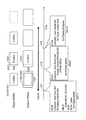
続いて本発明に係る記録媒体の実施行為のうち、生産行為についての形態について説明する。本発明に係る記録媒体は、BD-ROMの応用層に対する改良により実施することができる。図2は、BD-ROMの構成を示す図である。
本図の第4段目にBD-ROMを示し、第3段目にBD-ROM上のトラックを示す。本図のトラックは、BD-ROMの内周から外周にかけて螺旋状に形成されているトラックを、横方向に引き伸ばして描画している。このトラックは、リードイン領域と、ボリューム領域と、リードアウト領域とからなる。本図のボリューム領域は、物理層、ファイルシステム層、応用層というレイヤモデルをもつ。ディレクトリ構造を用いてBD-ROMの応用層フォーマット(アプリケーションフォーマット)を表現すると、図中の第1段目のようになる。本図に示すようにBD-ROMには、ROOTディレクトリの下にBDMVディレクトリがあり、BDMVディレクトリの配下には、AVClipを格納したファイル(XXX.M2TS)、AVClipの管理情報を格納したファイル(XXX.CLPI),AVClipにおける論理的な再生経路(PL)を定義したファイル(YYY.MPLS)が存在する。本図に示すようなアプリケーションフォーマットを作成することにより、本発明に係る記録媒体は生産される。尚、XXX.M2TS、XXX.CLPI,YYY.MPLSといったファイルが、それぞれ複数存在する場合は、BDMVディレクトリの配下に、STREAMディレクトリ、CLIPINFディレクトリ、PLAYLISTディレクトリという3つのディレクトリを設け、STREAMディレクトリにXXX.M2TSと同じ種別のファイルを、CLIPINFディレクトリにXXX.CLPIと同じ種別のファイルを、PLAYLISTディレクトリにYYY.MPLSと同じ種別のファイルを格納することが望ましい。
【0016】
このアプリケーションフォーマットにおけるAVClip(XXX.M2TS)について説明する。
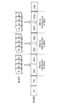
AVClip(XXX.M2TS)は、MPEG-TS(Transport Stream)形式のデジタルストリームであり、ビデオストリーム、1つ以上のオーディオストリーム、プレゼンテーショングラフィクスストリームを多重化することで得られる。ビデオストリームは映画の動画部分を、オーディオストリームは映画の音声部分を、プレゼンテーショングラフィクスストリームは、映画の字幕をそれぞれ示している。図3は、AVClipがどのように構成されているかを模式的に示す図である。
【0017】
AVClipは(中段)、複数のビデオフレーム(ピクチャpj1,2,3)からなるビデオストリーム、複数のオーディオフレームからなるオーディオストリームを(上1段目)、PESパケット列に変換し(上2段目)、更にTSパケットに変換し(上3段目)、同じくプレゼンテーショングラフィクスストリーム(下1段目)を、PESパケット列に変換し(下2段目)、更にTSパケットに変換して(下3段目)、これらを多重化することで構成される。
【0018】
本図において多重されるプレゼンテーショングラフィクスストリームは1つであるが、BD-ROMが多言語対応型である場合、その言語毎のプレゼンテーショングラフィクスストリームがAVClipに多重される。かかる過程を経て生成されたAVClipは、通常のコンピュータファイル同様、複数のエクステントに分割され、BD-ROM上の領域に記録される。
続いてプレゼンテーショングラフィクスストリームについて説明する。図4(a)は、プレゼンテーショングラフィクスストリームの構成を示す図である。第1段目は、AVClipを構成するTSパケット列を示す。第2段目は、グラフィクスストリームを構成するPESパケット列を示す。第2段目におけるPESパケット列は、第1段目におけるTSパケットのうち、所定のPIDをもつTSパケットからペイロードを取り出して、連結することにより構成される。
【0019】
第3段目は、グラフィクスストリームの構成を示す。グラフィクスストリームは、PCS(Presentation Composition Segment)、WDS(Window Defeine Segment)、PDS(Palette Difinition Segment)、ODS(Object_Definition_Segment)、END(END of Display Set Segment)と呼ばれる機能セグメントからなる。これらの機能セグメントのうち、PCSは、画面構成セグメントと呼ばれ、WDS,PDS,ODS,ENDは定義セグメントと呼ばれる。PESパケットと機能セグメントとの対応関係は、1対1の関係、1対多の関係である。つまり機能セグメントは、1つのPESパケットに変換されてBD-ROMに記録されるか、又は、フラグメント化され、複数PESパケットに変換されてBD-ROMに記録される。
【0020】
図4(b)は、機能セグメントを変換することで得られるPESパケットを示す図である。図4(b)に示すようにPESパケットは、パケットヘッダと、ペイロードとからなり、このペイロードが機能セグメント実体にあたる。またパケットヘッダには、この機能セグメントに対応するDTS、PTSが存在する。尚以降の説明では、機能セグメントが格納されるPESパケットのヘッダ内に存在するDTS及びPTSを、機能セグメントのDTS及びPTSとして扱う。
【0021】
これら様々な種別の機能セグメントは、図5のような論理構造を構築する。図5は、様々な種別の機能セグメントにて構成される論理構造を示す図である。本図は第3段目に機能セグメントを、第2段目にDisplay Setを、第1段目にEpochをそれぞれ示す。
第2段目のDisplay Set(DSと略す)とは、グラフィクスストリームを構成する複数機能セグメントのうち、一画面分のグラフィクスを構成するものの集合をいう。図中の破線は、第3段目の機能セグメントが、どのDSに帰属しているかという帰属関係を示す。PCS-WDS-PDS-ODS-ENDという一連の機能セグメントが、1つのDSを構成していることがわかる。再生装置は、このDSを構成する複数機能セグメントをBD-ROMから読み出せば、一画面分のグラフィクスを構成することができる。
【0022】
第1段目のEpochとは、AVClipの再生時間軸上においてメモリ管理の連続性をもっている一つの期間、及び、この期間に割り当てられたデータ群をいう。ここで想定しているメモリとは、一画面分のグラフィクスを格納しておくためのグラフィクスプレーン、伸長された状態のグラフィクスデータを格納しておくためのオブジェクトバッファである。これらについてのメモリ管理に、連続性があるというのは、このEpochにあたる期間を通じてこれらグラフィクスプレーン及びオブジェクトバッファのフラッシュは発生せず、グラフィックスプレーン内のある決められた矩形領域内でのみ、グラフィクスの消去及び再描画が行われることをいう(※ここでフラッシュとは、プレーン及びバッファの格納内容を全部クリアしてしまうことである。)。この矩形領域の縦横の大きさ及び位置は、Epochにあたる期間において、終始固定されている。グラフィックスプレーンにおいて、この固定化された領域内で、グラフィクスの消去及び再描画を行っている限り、映像とグラフィクスとの同期が保障される。つまりEpochは、映像−グラフィクスの同期の保障が可能な再生時間軸上の一単位ということができる。グラフィックスプレーンにおいて、グラフィクスの消去・再描画を行うべき領域を変更したい場合は、再生時間軸上においてその変更時点を定義し、その変更時点以降を、新たなEpochにせねばならない。この場合、2つのEpochの境界では、映像−グラフィクスの同期は保証されない。
【0023】
Epochにおける字幕の位置関係にたとえれば、再生時間軸上において、画面上のある決まった矩形領域内に字幕が出現している期間が、Epochということができる。図6は、字幕の表示位置と、Epochとの関係を示す図である。本図では、動画の各ピクチャの絵柄に応じて字幕の位置を変更するという配慮がなされている。つまり5つの字幕「本当は」「ウソだった」「あなたが」「ずっと」「すきだった」のうち、3つの字幕「本当は」「ウソだった」「あなたが」は画面の下側に、「ずっと」「すきだった」は画面の上側に配置されている。これは画面の見易さを考え、画面中の余白にあたる位置に字幕を配置することを意図している。かかる時間的な変動がある場合、AVClipの再生時間軸において、下側の余白に字幕が出現している期間が1つのEpoch1、上側の余白に字幕が出現している期間が別のEpoch2になる。これら2つのEpochは、それぞれ独自の字幕の描画領域をもつことになる。Epoch1では、画面の下側の余白が字幕の描画領域(window1)になる。一方Epoch2では、画面の上側の余白が字幕の描画領域(window2)になる。これらのEpoch1,2において、バッファ・プレーンにおけるメモリ管理の連続性は保証されているので、上述した余白での字幕表示はシームレスに行われる。以上がEpochについての説明である。続いてDisplay Setについて説明する。
【0024】
図5における破線hk1,2は、第2段目の機能セグメントが、どのEpochに帰属しているかという帰属関係を示す。Epoch Start,Acquisition Point,Normal Caseという一連のDSは、第1段目のEpochを構成していることがわかる。『Epoch Start』、『Acquisition Point』、『Normal Case』、『Epoch Continue』は、DSの類型である。本図におけるAcquisition Point、Normal Caseの順序は、一例にすぎず、どちらが先であってもよい。
【0025】
『Epoch Start』は、”新表示”という表示効果をもたらすDSであり、新たなEpochの開始を示す。そのためEpoch Startは、次の画面合成に必要な全ての機能セグメントを含んでいる。Epoch Startは、映画作品におけるチャプター等、頭出しがなされることが判明している位置に配置される。
『Acquisition Point』は、”表示リフレッシュ”という表示効果をもたらすDisplay Setであり、先行するEpoch Startと全く同じDisplay Setをいう。Acquisition PointたるDSは、Epochの開始時点ではないが、次の画面合成に必要な全ての機能セグメントを含んでいるので、Acquisition PointたるDSから頭出しを行えば、グラフィックス表示を確実に実現することができる。つまりAcquisition PointたるDSは、Epochの途中からの画面構成を可能するという役割をもつ。
【0026】
Acquisition PointたるDisplay Setは、頭出し先になり得る位置に組み込まれる。そのような位置には、タイムサーチにより指定され得る位置がある。タイムサーチとは、何分何秒という時間入力をユーザから受け付けて、その時間入力に相当する再生時点から頭出しを行う操作である。かかる時間入力は、10分単位、10秒単位というように、大まかな単位でなされるので、10分間隔の再生位置、10秒間隔の再生位置がタイムサーチにより指定され得る位置になる。このようにタイムサーチにより指定され得る位置にAcquisition Pointを設けておくことにより、タイムサーチ時のグラフィクスストリーム再生を好適に行うことができる。
【0027】
『Normal Case』は、”表示アップデート”という表示効果をもたらすDSであり、前の画面合成からの差分のみを含む。例えば、あるDSvの字幕は、先行するDSuと同じ内容であるが、画面構成が、この先行するDSuとは異なる場合、PCSのみのDSv、又は、PCSのみのDSvを設けてこのDSvをNormal CaseのDSにする。こうすれば、重複するODSを設ける必要はなくなるので、BD-ROMにおける容量削減に寄与することができる。一方、Normal CaseのDSは、差分にすぎないので、Normal Case単独では画面構成は行えない。
【0028】
『Epoch Continue』とは、AVClipの境界において、Epochが連続していることを示す。1つのDSnのComposition StateがEpoch Continueに設定されていれば、たとえDSnが、その直前に位置するDSn-1と異なるAVClip上に存在していたとしても、同じEpochに属することになる。これらDSn,DSn-1は、同じEpochに帰属するので、たとえこれら2つのDS間で、AVClipの分岐が発生したとしても、グラフィックスプレーン、オブジェクトバッファのフラッシュは発生しない。
続いてDefinition Segment(ODS,WDS,PDS)について説明する。
【0029】
『Object_Definition_Segment』は、グラフィクスオブジェクトを定義する機能セグメントである。このグラフィクスオブジェクトについて以下説明する。BD-ROMに記録されているAVClipは、ハイビジョン並みの高画質をセールスポイントにしているため、グラフィクスオブジェクトの解像度も、1920×1080画素という高精細な大きさに設定されている。1920×1080という解像度があるので、BD-ROMでは、劇場上映用の字幕の字体、つまり、手書きの味わい深い字体の字幕表示を鮮やかに再現できる。画素の色にあたっては、一画素当たりのインデックス値(赤色差成分(Cr値),青色差成分(Cb値),輝度成分Y値,透明度(T値))のビット長が8ビットになっており、これによりフルカラーの16,777,216色から任意の256色を選んで画素の色として設定することができる。グラフィクスオブジェクトによる字幕は、透明色の背景に、文字列を配置することで描画される。
【0030】
ODSによるグラフィクスオブジェクトの定義は、図7(a)に示すようなデータ構造をもってなされる。ODSは、図7(a)に示すように自身がODSであることを示す『segment_type』と、ODSのデータ長を示す『segment_length』と、EpochにおいてこのODSに対応するグラフィクスオブジェクトを一意に識別する『object_id』と、EpochにおけるODSのバージョンを示す『object_version_number』と、『last_in_sequence_flag』と、グラフィクスオブジェクトの一部又は全部である連続バイト長データ『object_data_fragment』とからなる。
【0031】
『object_id』は、EpochにおいてこのODSに対応するグラフィクスオブジェクトを一意に識別する。グラフィクスストリームのEpochには、同じIDをもつODSが複数含まれる。同じIDをもつ複数のODSは縦横のサイズが同じであり、オブジェクトバッファの共通の領域が割り当てられる。同じIDをもつ複数ODSのうち1つが、この領域に読み出されれば、オブジェクトバッファにおけるODSは、同じIDをもつ後続のODSにより上書きされる。このように、ビデオストリームの再生進行に伴い、オブジェクトバッファ上のODSが、同じ識別子をもつ後続のODSにて上書きされることにより、ODSにおける絵柄は、時間的な変遷を遂げる。同じIDをもつグラフィクスオブジェクトの縦横サイズを同じにするとの制限は、1つのEpoch内の制限に過ぎない。あるEpochに属するグラフィクスオブジェクトと、次のEpochに属するグラフィクスオブジェクトとでは縦横のサイズが変わっても良い。
【0032】
『last_in_sequence_flag』、『object_data_fragment』について説明する。PESパケットのペイロードの制限から、字幕を構成する非圧縮グラフィクスが1つのODSでは格納できない場合がある。そのような場合、グラフィクスを分割することにより得られた1部分(フラグメント)がobject_data_fragmentに設定される。1つのグラフィクスオブジェクトを複数ODSで格納する場合、最後のフラグメントを除く全てのフラグメントは同じサイズになる。つまり最後のフラグメントは、それ以前のフラグメントサイズ以下となる。これらフラグメントを格納したODSは、DSにおいて同じ順序で出現する。グラフィクスオブジェクトの最後は、last_in_sequence_flagをもつODSにより指示される。上述したODSのデータ構造は、前のPESパケットからフラグメントを詰めてゆく格納法を前提にしているが、各PESパケットに空きが生じるように、詰めてゆくという格納法であっても良い。以上がODSの説明である。
【0033】
『Palette Difinition Segment(PDS)』は、色変換用のパレットを定義する情報である。PDSのデータ構造を図7(b)に示す。図7(b)に示すようにPDSは、自身がPDSであることを示す『segment_type』、PDSのデータ長を示す『segment_length』、このPDSに含まれるパレットを一意に識別する『pallet_id』、EpochにおけるEpochのPDSのバージョンを示す『pallet_version_number』、各エントリーについての情報『pallet_entry』からなる。『pallet_entry』は、各エントリーにおける赤色差成分(Cr値),青色差成分(Cb値),輝度成分Y値,透明度(T値)を示す。
【0034】
続いてWDSについて説明する。
『window_definition_segment』は、グラフィックスプレーンの矩形領域を定義するための機能セグメントである。Epochでは、クリア及び再描画が、グラフィックスプレーンにおけるある矩形領域内で行われている場合のみ、メモリ管理に連続性が生ずることは既に述べている。このグラフィックスプレーンにおける矩形領域は”window”と呼ばれ、このWDSで定義される。図8(a)は、WDSのデータ構造を示す図である。本図に示すようにWDSは、グラフィックスプレーンにおいてウィンドゥを一意に識別する『window_id』と、グラフィックスプレーンにおける左上画素の水平位置を示す『window_horizontal_position』と、グラフィックスプレーンにおける左上画素の垂直位置を示す『window_vertical_position』と、グラフィックスプレーンにおけるウィンドゥの横幅を示す『window_width』と、グラフィックスプレーンにおける縦幅を示す『window_height』とを用いて表現される。
【0035】
window_horizontal_position、window_vertical_position、window_width、window_heightがとりうる値について説明する。これらが想定している座標系は、グラフィックスプレーンの内部領域であり、このグラフィックスプレーンの内部領域においてウィンドゥは、縦:video_height、横:video_widthという二次元状の大きさをもつ。
window_horizontal_positionは、グラフィックスプレーンにおける左上画素の水平アドレスであるので、0〜video_width-1の値をとり、window_vertical_positionは、グラフィックスプレーンにおける左上画素の垂直アドレスであるので0〜video_height-1の値をとる。
【0036】
window_widthは、グラフィックスプレーンにおけるウィンドゥの横幅であるので、0〜video_width-window_horizontal_position-1の値をとり、window_heightは、グラフィックスプレーンにおける縦幅であるので0〜video_height-window_vertical_position-1の値をとる。
WDSのwindow_horizontal_position、window_vertical_position、window_width、window_heightにより、グラフィックスプレーンの何処にウィンドゥを配置するか、ウィンドゥの大きさをどれだけにするかをEpoch毎に規定することができる。そのため、あるEpochに属するピクチャが表示されている期間において、ピクチャ内の絵柄の邪魔にならないように、ピクチャ上の余白にあたる位置に、ウィンドゥが現れるようオーサリング時に調整しておくことができる。これによりグラフィクスによる字幕表示を見易くすることができる。WDSはEpoch毎に定義可能なので、ピクチャの絵柄に時間的な変動があっても、その変動に応じて、グラフィクスを見易く表示することができる。そのため、結果として、字幕を映像本体に組み込むのと同じレベルにまで映画作品の品質を高めることができる。
【0037】
続いて『END of Display Set Segment』について説明する。END of Display Set Segmentは、Display Setの伝送の終わりを示す指標であり、Display Setにおける機能セグメントのうち、最後のODSの直後に配置される。この END of Display SetSegmentの内部構成は、自身が END of Display SetSegmentであることを示す『segment_type』と、当該機能セグメントのデータ長を示す『segment_length』とからなり、これといって説明が必要な構成要素はない。故に図示は省略する。
【0038】
以上がODS、PDS、WDS、ENDについての説明である。続いてPCSについて説明する。
PCSは、対話的な画面を構成する機能セグメントである。PCSは、図8(b)に示すデータ構造で構成される。本図に示すようにPCSは、『segment_type』と、『segment_length』と、『composition_number』と、『composition_state』と、『pallet_update_flag』と、『pallet_id』と、『composition_object(1)〜(m)』とから構成される。
【0039】
『composition_number』は、0から15までの数値を用いてDisplay Setにおけるグラフィクスアップデートを識別する。どのように識別するかというと、Epochの先頭から本PCSまでにグラフィクスアップデートが存在すれば、それらグラフィクスアップデートを経由する度に、インクリメントされるというルールでcomposition_numberは設定される。
『composition_state』は、本PCSから始まるDisplay Setが、Normal Caseであるか、ACquisition Pointであるか、Epoch Startであるかを示す。
【0040】
『pallet_update_flag』は、本PCSにおいてPalletOnly Displey Updateがなされているかどうかを示す。PalletOnly Displey Updateとは、直前のパレットのみを新たなものに切り換えることでなされるアップデートをいう。本PCSでかかるアップデートがなされれば、本フィールドは”1”に設定される。
『pallet_id』は、PalletOnly Displey Updateに用いられるべきパレットを示す。
【0041】
『composition_object(1)・・・(n)』は、このPCSが属するDisplay Set内の、個々のウィンドゥをどのように制御するかを示す情報である。図8(b)の破線wd1は、任意のcomposition_object(i)の内部構成をクローズアップしている。この破線wd1に示すように、composition_object(i)は、『object_id』、『window_id』、『object_cropped_flag』、『object_horizontal_position』、『object_vertical_position』、『cropping_rectangle情報(1)(2)・・・・・(n)』からなる。
【0042】
『object_id』は、composition_object(i)に対応するウィンドゥ内に存在するODSの識別子を示す。
『window_id』は、本PCSにおいて、グラフィクスオブジェクトに割り当てられるべきウィンドゥを示す。1つのウィンドゥには最大2つのグラフィクスオブジェクトが割り当てられる。
【0043】
『object_cropped_flag』は、オブジェクトバッファにおいてクロップされたグラフィクスオブジェクトを表示するか、グラフィクスオブジェクトを非表示とするかを切り換えるフラグである。”1”と設定された場合、オブジェクトバッファにおいてクロップされたグラフィクスオブジェクトが表示され、”0”と設定された場合、グラフィクスオブジェクトは非表示となる。
【0044】
『object_horizontal_position』は、グラフィックスプレーンにおけるグラフィクスオブジェクトの左上画素の水平位置を示す。
『object_vertical_position』は、グラフィックスプレーンにおける左上画素の垂直位置を示す。
『cropping_rectangle情報(1)(2)・・・・・(n)』は、『object_cropped_flag』が1に設定されている場合に有効となる情報要素である。破線wd2は、任意のcropping_rectangle情報(i)の内部構成をクローズアップしている。この破線に示すようにcropping_rectangle情報(i)は、『object_cropping_horizontal_position』、『object_cropping_vertical_address』、『object_cropping_width』、『object_cropping_height』からなる。
【0045】
『object_cropping_horizontal_position』は、グラフィックスプレーンにおけるクロップ矩形の左上画素の水平位置を示す。クロップ矩形は、グラフィクスオブジェクトの一部を切り出すための枠であり、ETSI EN 300 743標準規格における”Region”に相当する。
『object_cropping_vertical_address』は、グラフィックスプレーンにおけるクロップ矩形の左上画素の垂直位置を示す。
【0046】
『object_cropping_width』は、グラフィックスプレーンにおけるクロップ矩形の横幅を示す。
『object_cropping_height』は、グラフィックスプレーンにおけるクロップ矩形の縦幅を示す。
以上がPCSのデータ構造である。続いてPCSの具体的な記述について説明する。この具体例は、図6に示した字幕の表示、つまり動画の再生進行に伴い、三回のグラフィックスプレーンへの書き込みで『ほんとは』『ウソだった』『あなたが』というように徐々に表示させるというものである。図9は、かかる字幕表示を実現するための記述例である。本図におけるEpochは、DS1(Epoch Start)、DS2(Normal Case)、DS3(Normal Case)を有する。DS1は、字幕の表示枠となるwindowを定義するWDS、台詞『ほんとは ウソだった あなたが』を表すODS、1つ目のPCSを備える。DS2(Normal Case)は、2つ目のPCSを有する。DS3(Normal Case)は3つ目のPCSを有する。
【0047】
次に個々のPCSをどのように記述するかについて説明する。Display Setに属するWDS、PCSの記述例を図10〜図12に示す。図10は、DS1におけるPCSの記述例を示す図である。
図10において、WDSのwindow_horizontal_position、window_vertical_positionは、グラフィックスプレーンにおけるウィンドゥの左上座標LP1を、window_width,window_heightは、ウィンドゥの表示枠の横幅、縦幅を示す。
【0048】
図10におけるクロップ情報のobject_cropping_horizontal_position,object_cropping_vertical_positionは、オブジェクトバッファにおけるグラフィクスオブジェクトの左上座標を原点とした座標系においてクロップ範囲の基準ST1を示している。そして基準点からobject_cropping_width、object_cropping_heightに示される範囲(図中の太枠部分)がクロップ範囲になる。クロップされたグラフィクスオブジェクトは、グラフィックスプレーンの座標系においてobject_horizontal_position,object_vertical_positionを基準点(左上)とした破線の範囲cp1に配置される。こうすることにより、『本当は』がグラフィックスプレーンにおけるウィンドゥ内に書き込まれる。これにより字幕『本当は』は動画像と合成され表示される。
【0049】
図11は、DS2におけるPCSの記述例を示す図である。本図におけるWDSの記述は、図10と同じなので説明を省略する。クロップ情報の記述は、図10と異なる。図11におけるクロップ情報のobject_cropping_horizontal_position,object_cropping_vertical_position,は、オブジェクトバッファ上の字幕『本当はウソだった。あなたが』のうち、『ウソだった』の左上座標を示し、object_cropping_height,object_cropping_widthは、『ウソだった』の横幅、縦幅を示す。こうすることにより、『ウソだった』がグラフィックスプレーンにおけるウィンドゥ内に書き込まれる。これにより字幕『ウソだった』は動画像と合成され表示される。
【0050】
図12は、DS3におけるPCSの記述例を示す図である。本図におけるWDSの記述は、図10と同じなので説明を省略する。クロップ情報の記述は、図10と異なる。図12におけるクロップ情報のobject_cropping_horizontal_position,object_cropping_vertical_position,は、オブジェクトバッファ上の字幕『本当はウソだった。あなたが』のうち、『あなたが』の左上座標を示し、object_cropping_height,object_cropping_widthは、『あなたが』の横幅、縦幅を示す。こうすることにより、『あなたが』がグラフィックスプレーンにおけるウィンドゥ内に書き込まれる。これにより字幕『あなたが』は動画像と合成され表示される。
【0051】
DS1,2,3のPCSを以上のように記述することで、字幕の表示効果を実現することができる。その他の表示効果を実現するにあたっての、PCSの記述作法について説明する。
先ず初めにCut-In/Outの記述作法について説明する。図13は、時間軸に沿った連続写真的な表記で、Cut-In/Outを実行する際のDisplay Setの記述例を示す図である。
本図におけるwindow(x,y,u.v)におけるx,yは、window_vertical_position、window_horizontal_positionの値であり、u,vは、window_width、window_heightの値を示す。また本図のCropping Rectangle(a,b,c,d)におけるa,bは、object_cropping_vertical_position、object_cropping_horizontal_positionの値であり、c,dはobject_cropping_width、object_cropping_heightの値である。本図の再生時間軸の時点t11,t12,t13には、DS11,DS12,DS13が存在している。
【0052】
時点t11に存在するDS11は、Composition_StateがEpoch Startに設定され、Object_Cropped_Flagが0(No Cropping Rectangle Visible)に設定されたPCS#0、グラフィックスプレーンの(100,100)の位置に、横700×縦500のwindowを宣言するWDS#0、PDS#0、字幕「Credit:」を表すODS#0、ENDを有する。
時点t12に存在しているDS12は、Composition_StateがNormal Caseであり、オブジェクトバッファの(0,0)から横600×縦400の範囲でクロップを行い(Cropping Rectangle#0(0,0,600,400))、クロップされたグラフィクスオブジェクトをグラフィックスプレーンの座標(0,0)に配置する(on window(0,0))という手順を示すPCS#1を含む。
【0053】
時点t13に存在しているDS13は、Composition_StateがNormal Caseであり、クロップされたグラフィクスオブジェクトを消すよう、object_cropped_flagが0に設定されたPCS#2を含む(No Cropping Rectangle Visible)。
以上のDisplay Setにより、t11では字幕「Credit:」は非表示になっているが、t12で表示され、t13で再び非表示になる。これによりCut-In/Cut-Outという表示効果が実現される。
【0054】
続いてFade-In/Outという表示効果を実現する際の、Display Setの記述作法について説明する。図14は、時間軸に沿った連続写真的な表記で、Fade-In/Outを実行する際のDisplay Setの記述例を示す図である。本図の時点t21,t22,t23,t24には、DS21,DS22,DS23,DS24が存在している。
時点t21に存在するDS21は、Composition_StateがEpoch Startに設定され、オブジェクトバッファの(0,0)から横600×縦400の範囲でクロップを行い(Cropping Rectangle#0(0,0,600,400))、クロップされたグラフィクスオブジェクトをグラフィックスプレーンの座標(0,0)に配置する(on window(0,0))という手順を示すPCS#0、グラフィックスプレーンの(100,100)の位置に、横700×縦500のwindowを宣言するWDS#0、PDS#0、字幕「Fin」を表すODS#0、ENDを有する。
【0055】
時点t22に存在しているDS22は、Composition_StateがNormal CaseであるPCS#1と、PDS#1とを含む。このPDS#1は、PDS#0と同じ色彩の赤色差、青色差を示しておりながら、高い輝度値をもっているものとする。
時点t23に存在しているDS23は、Composition_StateがNormal CaseであるPCS#3と,PDS#2と,ENDとを含む。このPDS#2は、PDS#0と同じ色彩の赤色差、青色差を示しておりながら、低い輝度値をもっているものとする。
【0056】
時点t24に存在するDS24は、Composition_StateがNormal Caseに設定され、Object_Cropped_Flagが0(No Cropping Rectangle Visible)に設定されたPCS、ENDを有する。
これら一連のDisplay Setは、1つ前のDisplay Setと異なるPDSを指定しているため、Epoch内の複数PCSにおいて表示されるグラフィクスオブジェクトは、徐々に輝度値が高められたり、弱められることになる。これによりFade-In/Outという表示効果の実現が可能になる。
【0057】
続いてScrollingの記述作法について説明する。図15は、時間軸に沿った連続写真的な表記で、Scrollingがどのように行われるかを記述した図である。本図における表記は、図13の一例に準ずる。
AVClip再生時間軸の時点t31に存在するDS31は、Composition_StateがEpoch Startに設定され、Object_Cropped_Flagが0(No Cropping Rectangle Visible)に設定されたPCS#0、グラフィックスプレーンの(100,100)の位置に、横700×縦500のwindowを宣言するWDS#0、PDS#0、字幕「Credit: Company」を表すODS#0、ENDを有する。
【0058】
時点t32に存在するDS32は、Composition_StateがNormal Caseであり、オブジェクトバッファにおける(0,0)から横600×縦400の範囲でクロップを行い(Cropping Rectangle#0(0,0,600,400))、クロップされたグラフィクスオブジェクトをグラフィックスプレーンの座標(0,0)に配置する(on window#0(0,0))という手順を示すPCS#1を含む。オブジェクトバッファにおいて(0,0)から横600×縦400の範囲には、「Credit:」「Company」という2段表記の字幕のうち「Credit:」が存在するので、この「Credit:」がグラフィックスプレーンに出現することになる。
【0059】
時点t33に存在するDS33は、Composition_StateがNormal Caseであり、オブジェクトバッファ上の座標(0,100)から横600×縦400の範囲を切り出し(Cropping Rectangle#0(0,100,600,400))、ウィンドゥにおける座標(0,0)に配置する(on window#0(0,0))という手順を示すPCS#2を含む。オブジェクトバッファ上の座標(0,100)から横600×縦400の範囲には、「Credit:」「Company」という2段表記の字幕のうち、「Credit:」の下半分と、「Company」の上半分とが存在するので、これらの部分がグラフィックスプレーンに出現することになる。
【0060】
時点t34に存在するDS34は、Composition_StateがNormal Caseであり、オブジェクトバッファの座標(0,200)から横600×縦400の範囲を切り出し(Cropping Rectangle#0(0,200,600,400))、ウィンドゥにおける座標(0,0)に配置する(on window#0(0,0))という手順を示すPCS#3を含む。オブジェクトバッファ上の座標(0,200)から横600×縦400の範囲には、「Credit:」「Company」という2段表記の字幕のうち、「Company」が存在するので、2段表記の字幕のうち「Company」の部分が画面上に現れることになる。以上のPCSの記述により、「Credit:」「Company」という2段表記の字幕の下スクロールがなされることになる。
【0061】
続いてWipe-In/Outの記述作法について説明する。図16は、時間軸に沿った連続写真的な表記で、Wipe-In/Outがどのように行われるかを記述した図である。本図における表記は、図13の一例に準ずる。
本図の時点t51に存在するDS51は、Composition_StateがEpoch Startに設定され、Object_Cropped_Flagが0(No Cropping Rectangle Visible)に設定されたPCS#0、グラフィックスプレーンの(100,100)の位置に、横700×縦500のwindowを宣言するWDS#0、PDS#0、字幕「Fin」を表すODS#0、ENDを有する。
【0062】
時点t52に存在するDS52は、Composition_StateがNormal Caseであり、オブジェクトバッファの(0,0)から横600×縦400の範囲でクロップを行い(Cropping Rectangle#0(0,0,600,400))、クロップされたグラフィクスオブジェクトをグラフィックスプレーンの座標(0,0)に配置する(on window#0(0,0))という手順を示すPCS#1を含む。(0,0)から横600,縦400の範囲には、「Fin」という字幕が存在するので、この「Fin」がグラフィックスプレーンに出現することになる。
【0063】
時点t53に存在するDS53は、Composition_StateがNormal Caseであり、オブジェクトバッファにおける(200,0)から縦400×横400の範囲でクロップを行い(Cropping Rectangle#0(200,0,400,400))、座標(200,0)を基準にして、表示を行わせるPCS#2を含む(on window#0(200,0))。そうすると、(200,0)〜(400,400)が表示範囲内になり、(0,0)〜(199,400)は、非表示範囲になる。
【0064】
時点t54に存在するDS54は、Composition_StateがNormal Caseであり、オブジェクトバッファにおけるグラフィクスオブジェクトの(400,0)から横200×縦400の範囲でクロップを行い(Cropping Rectangle#0(400,0,200,400))、座標(400,0)を基準にして、ウィンドゥの表示を行わせる(on window#0(400,0))PCS#3を含む。そうすると、(0,0)〜(399,400)は、非表示範囲になる。
【0065】
グラフィックスプレーンの非表示範囲が広がるに伴い、表示範囲が狭まるのでWipe-In/Outが実現されることになる。
このようにPCSの記述次第でCut-In/Out,Fade-In/Out,Wipe-In/Out,Scrollというような多様な表示効果を実現することができるので、字幕描画に様々な工夫を凝らすことができる。
【0066】
かかる表示効果実現にあたっての制約について説明する。図13〜図16の表示効果のうち、Scrollingの実現には、ウィンドゥクリアと、ウィンドゥ再描画とが必要になる。図15のt32−t33間で考えれば、Scrollingの実現のためには、t32における「Credit:」なるグラフィクスオブジェクトをグラフィックスプレーンから消し去るというウィンドゥクリアと、「Credit:」の下半分、「Company」の上半分をグラフィックスプレーンに書き込むというウィンドゥ再描画とをt32−t33の時間間隔で実現せねばならない。この時間間隔がビデオフレームの時間間隔である場合、オブジェクトバッファと、グラフィックスプレーンとの間の転送レートはどれだけ必要であろうか。
【0067】
ここでウィンドゥをどれだけの大きさとするかの制限について検討する。オブジェクトバッファ−グラフィックスプレーン間の転送レートをRcとすると、ワーストケースでは、この転送レートRcでウィンドゥクリアと、ウィンドゥ再描画とを行わねばならない。そうするとウィンドゥクリア、ウィンドゥ再描画のそれぞれをRcの半分の転送レート(Rc/2)で実現せねばならない。
【0068】
これらウィンドゥクリア−ウィンドゥ再描画をビデオフレームと同期させるには、
ウィンドゥサイズ×フレームレート≒Rc/2
を満たす必要がある。このフレームレートが29.97であるなら、
Rcは、ウィンドゥサイズ×2×29.97になる。
字幕の表示にあたっては、グラフィックスプレーン全体に対し、最低でも25%〜33%程度の大きさが必要となる。ここでグラフィックスプレーンの総画素数は1920×1080であり、一画素当たりのインデックスのビット長を8ビットとすると、グラフィックスプレーンの総容量は2Mバイト(≒1920×1080×8)になる。
【0069】
この総容量の1/4をウィンドゥサイズとすると、500kバイト(=2Mバイト/4)になる。これを上述した式に代入してRcを導けば、Rcは256Mbps(500Kバイト×2×29.97)と算出することができる。
この25%〜33%という大きさであれば、256Mbpsという転送レートで字幕の表示を行っている限り、如何なる表示効果を実現する場合であっても、動画との同期を維持することができる。
【0070】
仮に、ウィンドゥクリア及び再描画のレートがビデオフレームのフレームレートの1/2,1/4でよいなら、Rcがたとえ同じであってもウィンドゥサイズを2倍,4倍にすることができる。以上がwindowの大きさについての説明である。続いて、windowの位置、範囲について説明する。上述したように、Epochにおいてウィンドゥの位置、範囲は一貫している。
Epochにおいてウィンドゥの位置、範囲を一貫させておくのは以下の理由による。ウィンドゥの位置・範囲を変えれば、グラフィックスプレーンに対する書込先アドレスを変えねばならず、オーバーヘッドが発生するので、かかるオーバーヘッドによりオブジェクトバッファからグラフィックスプレーンへの転送レートが低下するからである。
【0071】
ウィンドゥには、グラフィクスオブジェクトの個数が制限されている。この個数制限は、デコードされたグラフィクスオブジェクトの転送にあたってのオーバーヘッドを低減する目的で設けられている。ここでのオーバーヘッドは、グラフィクスオブジェクトのエッジ部分のアドレスを設定する際に発生する。そうすれば、エッジの部分が多く存在する程、オーバーヘッドの発生回数が多くなる。
【0072】
図17は、ウィンドゥ内にグラフィクスオブジェクトが4つ存在する場合と、2つの存在する場合とを対比して示す図である。グラフィクスオブジェクトが4つ存在する場合、エッジの数は8つになるのでグラフィクスオブジェクトが2つ存在する場合と比べると、エッジの数は2倍になっている。
ウィンドゥにおけるグラフィクスオブジェクトの数に制限がないと、グラフィクス転送にあたって発生するオーバーヘッド数が未知数になり、転送負荷の増減が激しくなる。一方、ウィンドゥにおけるグラフィクスの個数が2つまでであると、最悪4つのオーバーヘッドが発生すると見込んで転送レートを設定すればよいので、ミニマムスタンダードたる転送レートを数値化し易くなる。
【0073】
以上がウィンドゥについての説明である。続いてこれらPCS、ODSを有したDisplay Setが、AVClipの再生時間軸上にどのように割り当てられるかについて説明する。Epochは、再生時間軸上においてメモリ管理が連続する期間であり、Epochは1つ以上のDisplay Setから構成されるので、Display SetをどうやってAVClipの再生時間軸に割り当てるかが問題になる。ここでAVClipの再生時間軸とは、AVClipに多重されたビデオストリームを構成する個々のピクチャデータのデコードタイミング、再生タイミングを規定するための想定される時間軸をいう。この再生時間軸においてデコードタイミング、再生タイミングは、90KHzの時間精度で表現される。Display Set内のPCS、ODSに付加されたDTS、PTSは、この再生時間軸において同期制御を実現すべきタイミングを示す。このPCS、ODSに付加されたDTS、PTSを用いて同期制御を行うことが、再生時間軸へのDisplay Setの割り当てである。
【0074】
先ず、ODSに付加されたDTS、PTSにより、どのような同期制御がなされるかについて説明する。
DTSは、ODSのデコードを開始すべき時間を90KHzの時間精度で示しており、PTSはデコード終了時刻を示す。
ODSのデコードは、瞬時には完了せず、時間的な長さをもっている。このデコード期間の開始点・終了点を明らかにしたいとの要望から、ODSについてのDTS、PTSはデコード開始時刻、デコード終了時刻を示している。
【0075】
PTSの値はデッドラインであるので、PTSに示される時刻までにODSのデコードがなされて、非圧縮状態のグラフィックオブジェクトが、再生装置上のオブジェクトバッファに得られなければならない。
DSnに属する任意のODSjのデコード開始時刻は、90KHzの時間精度でDTS(DSn[ODS])に示されるので、これにデコードを要する最長時間を加えた時刻が、Display SetのODSjのデコード終了時刻になる。
【0076】
ODSjのサイズを”SIZE(DSn[ODSj])”、ODSのデコードレートを”Rd”とすると、デコードに要する最長時間(秒)は、”SIZE(DSn[ODSj])//Rd”になる。ここで”//”は、小数点以下切り上げの割り算を示す演算子である。
この最長時間を90KHzの時間精度に変換し、ODSjのDTSに加算することにより、PTSで示されるべきデコード終了時刻(90KHz)は算出される。
DSnに属するODSjのPTSを、数式で表すと、以下の式のようになる。
PTS(DS[ODSj])=DTS(DSn[ODSj])+90,000×(SIZE(DSn[ODSj])//Rd)
そして互いに隣接する2つのODS(ODSj,ODSj+1)との間では、以下の関係を満たす必要がある。
PTS(DSn[ODSj])≦DTS(DSn[ODSj+1])
続いてPCSのDTS、PTSの設定について説明する。
【0077】
PCSは、DSnにおける最初のODS(ODS1)のデコード開始時点(DTS(DSn[ODS1]))以前、及び、DSnにおける最初のPDS(PDS1)が有効になる時点(PTS(DSn[PDS1]))以前に、再生装置上のバッファにロードされねばならない。よって以下の式の関係を満たす値に、設定されねばならない。
DTS(DSn[PCS])≦DTS(DSn[ODS1])
DTS(DSn[PCS])≦PTS(DSn[PDS1])
そしてDSnにおけるPCSのPTSは、以下の数式から算出される。
PTS(DSn[PCS])≧DTS(DSn[PCS])+decodeduration(DSn)
ここでdecodeduration(DSn)は、PCSのアップデートに用いられる全グラフィクスオブジェクトのデコード時間である。このデコード時間は、固定値ではない。しかし各再生装置の状態や再生装置の実装により変動するものでもない。本DSn.PCSnの画面合成に用いられるオブジェクトをDSn.PCSn.OBJ[j]とした場合、decodeduration(DSn)は、ウィンドゥクリアに要する時間(i)、DSn.PCSn.OBJのデコード期間(ii)、DSn.PCSn.OBJの書き込みに要する時間(iii)により変動を受ける値になる。Rd,Rcさえ予め定められていれば、どのような実装の再生装置であっても、同じ値になる。そのためオーサリング時にあたっては、これらの期間の長さを算出して、この値からPTSを計算している。
【0078】
decode_durationの計算は、図18のプログラムに基づき行われる。また図19、図20(a)(b)は、このプログラムのアルゴリズムを図式化したフローチャートである。以降、これらの図を参照しながらdecode_durationの算出について説明する。図19のフローチャートにおいて、先ず初めに、PLANEINITIALIZATINTIME関数を呼び出し、戻り値をdecode_durationに加算する(図19のステップS1)。PLANEINITIALIZATINTIME関数(図20(a))は、Display Setを表示するにあたってグラフィックスプレーンの初期化に要する時間を求める関数を呼出すための関数であり、図19のステップS1では、DSn,DSnPCS.OBJ[0],decode_durtationを引数に設定して、この関数を呼び出す。
【0079】
続いて図20(a)を参照しながらPLANEINITIALIZATINTIME関数について説明する。図20(a)においてinitialize_durationとは、PLANEINITIALIZATINTIME関数の戻り値を示す変数である。
図20のステップS2は、DSnのPCSにおけるcomposition_stateがEpoch Startかどうかにより、処理を切り換えるif文である。もしcomposition_stateがEpoch Startであるなら(図18のDSn.PCS.composition_state==EPOCH_START、ステップS2=Yes)、グラフィックスプレーンのクリアに要する時間をinitialize_durationに設定する(ステップS3)。
【0080】
オブジェクトバッファ−グラフィックスプレーン間の転送レートRcを上述したように256,000,000とし、グラフィックスプレーンの総サイズをvideo_width*video_heightとすると、クリアに要する時間(秒)は、「video_width*video_height//256,000,000」になる。これに、90.000Hzを乗じPTSの時間精度で表現すれば、グラフィックスプレーンのクリアに要する時間は「90000×video_width*video_height//256,000,000」になる。この時間を、initialize_durationに加えて、initialize_durationを戻り値としてリターンする。
【0081】
もしcomposition_stateがEpoch Startでないなら(ステップS2=No)、WDSにて定義されるwindow[i]のクリアに要する時間をinitialize_durationに加えるという処理を全てのwindowについて繰り返す(ステップS4)。オブジェクトバッファ−グラフィックスプレーン間の転送レートRcを上述したように256,000,000とし、WDSに属するウィンドゥ[i]の総サイズをΣSIZE(WDS.WIN[i])とすると、クリアに要する時間(秒)は、「ΣSIZE(WDS.WIN[i])//256,000,000」になる。これに、90.000Hzを乗じPTSの時間精度で表現すれば、WDSに属する全ウィンドゥのクリアに要する時間は「90000×ΣSIZE(WDS.WIN[i]))//256,000,000」になる。この時間を、initialize_durationに加えて、initialize_durationを戻り値としてリターンする。以上がPLANEINITIALIZATINTIME関数である。
【0082】
図19のステップS5は、DSnに属するグラフィクスオブジェクトの数が2であるか、1であるかで処理を切り換えるものであり(図18のif(DSn.PCS.num_of_object==2),if(DSn.PCS.num_of_object==1))、もし”1”であるなら(ステップS5=1)、グラフィクスオブジェクトのデコードを行うための待ち時間をdecode_durationに加える(ステップS6)。この待ち時間の算出は、WAIT関数の呼出(図18のdecode_duration +=WAIT(DSn,DSn.PCS.OBJ[0],decode_duration))で実現される。この関数呼出にあたっての引数はDSn,DSn.PCS.OBJ[0],decode_durationであり、待ち時間を示すwait_durationが戻り値として返される。
【0083】
図20(b)は、WAIT関数の処理手順を示すフローチャートである。
このWAIT関数においてcurrent_durationとは、呼出元のdecode_durationが設定される。object_define_ready_timeは、Display Setのグラフィクスオブジェクト[i]のPTSが設定される変数である。
current_timeとは、DSnのPCSのDTSに、current_durationを足した値が設定される変数である。このcurrent_timeよりobject_define_ready_timeが大きい場合(ステップS7がYes、if(current_time < object_define_ready_time))、戻り値たるwait_durationは、object_define_ready_timeとcurrent_timeとの差分が設定されることになる(ステップS8、wait_duration += object_define_ready_time - current_time)。以上がWait関数である。ステップS6においてdecode_durationには、このwait関数の戻り値と、window再描画に必要な時間を足し合わせた時間(90,000*(SIZE(DSn.WDS.WIN[0]))//256,000,000)が設定されることになる。
【0084】
以上はDSnのグラフィクスオブジェクトが1つである場合の処理である。図19のステップS5は、グラフィクスオブジェクトの数が2であるかどうかを判定している。DSnのグラフィクスオブジェクトが2以上であれば(図18のif(DSn.PCS.num_of_object==2))、PCSにおけるOBJ[0]を引数として、wait関数を呼び出し、その戻り値をdecode_durationに加算する(ステップS10)。
【0085】
続くステップS11は、DSnのOBJ[0]が属するwindowが、グラフィクスオブジェクト[1]が属するwindowと同一かどうかの判定であり(if(DSn.PCS.OBJ[0].window_id == DSn.PCS.OBJ[1].window_id)、もし同一であるなら、OBJ[1]を引数にしてwait関数を呼び出し、その戻り値wait_durationを、decode_durationに加算する(ステップS12)。OBJ[0]が属するwindowの再描画に必要な時間(90,000*(SIZE(DSn.WDS.OBJ[0].window_id)//256,000,000)をdecode_durationに加える(ステップS13)。
【0086】
もし属するwindowが異なるなら(ステップS11で”異なる”)、OBJ[0]が属するwindowの再描画に必要な時間(90,000*(SIZE(DSn.WDS.OBJ[0].window_id)//256,000,000)をdecode_durationに加える(ステップS15)。OBJ[1]を引数にしてwait関数を呼び出し、その戻り値wait_durationを、decode_durationに加算する(ステップS16)。その後、OBJ[1]が属するwindowの再描画に必要な時間(90,000*(SIZE(DSn.WDS.OBJ[1].window_id)//256,000,000)をdecode_durationに加える(ステップS17)。
【0087】
以上のアルゴリズムにより、Decode_Durationは算出される。このPCSのPTSが、具体的にどのように設定されるかについて説明する。
図21(a)は、1つのwindowに1つのODSが存在するケースを想定した図である。図21(b)(c)は、図18で引用した各数値の時間的な前後関係を示すタイミングチャートである。本チャートには3つの段があり、これらの段のうち、”グラフィックスプレーンアクセス”の段、”ODSデコード”の段は、再生時にパラレルになされる2つの処理を示す。上述したアルゴリズムは、これらの2つの処理のパラレル実行を想定している。
【0088】
グラフィックスプレーンアクセスは、クリア期間(1)、書き込み期間(3)からなる。このクリア期間(1)は、グラフィックスプレーン全体のクリアに要する期間(90,000×(グラフィックスプレーンのサイズ//256,000,000))、グラフィックスプレーンにおける全windowのクリアに要する時間(Σ(90,000×(window[i]のサイズ//256,000,000)))のどちらかを意味する。
【0089】
書き込み期間(3)は、window全体描画に要する期間(90,000×(windowサイズ//256,000,000))を意味する。
一方、デコード期間(2)は、ODSのDTSからPTSまでに示される期間を意味する。 これらクリア期間(1)〜書き込み期間(3)は、クリアすべき範囲、デコードすべきODSのサイズ、グラフィックスプレーンに書き込むべきグラフィクスオブジェクトのサイズにより変化し得る。本図では、説明の簡略化のため、ODSのデコード期間(2)の始点は、クリア期間(1)の始点と同一であると仮定している。
【0090】
図21(b)はデコード期間(2)が長くなるケースであり、Decode_Durationはデコード期間(2)+書き込み期間(3)になる。
図21(c)は、クリア期間(1)が長くなるケースであり、Decode_Durationはクリア期間(1)+書き込み期間(3)の期間がDecode_Durationになる。
図22(a)〜(c)は、1つのwindowに2つのODSが存在するケースを想定した図である。本図(b)(c)におけるデコード期間(2)は、2つのグラフィクスのデコードに要する期間の総和を意味する。グラフィクス書込期間(3)も、2つのグラフィクスをグラフィックスプレーンに書き込む期間の総和を意味する。
ODSが2つになっているものの、図21と同様に考えればDecode_Durationを算出することができる。2つのODSをデコードするためのデコード期間(2)が長い場合は、図22(b)に示すようにDecode_Durationはデコード期間(2)+書き込み期間(3)に算出されることになる。
【0091】
クリア期間(1)が長い場合は、図22(c)に示すように、Decode_Durationはクリア期間(1)+書き込み期間(3)となる。
図23(a)は、2つのwindowのそれぞれに、ODSが1つずつ存在するケースを想定している。この場合でもクリア期間(1)が、2つのODSをデコードするための総デコード期間(2)よリ長い場合、Decode_Durationはクリア期間(1)+書き込み期間(3)になる。問題は、クリア期間(1)がデコード期間(2)より短くなるケースである。この場合デコード期間(2)の経過を待たずに、1つ目のwindowへの書き込みは可能になる。そのためクリア期間(1)+書き込み期間(3)、デコード期間(2)+書き込み期間(3)の長さにはならない。ここで1つ目のODSのデコードに要する期間を書込期間(31)、2つ目のODSのデコードに要する期間を書込期間(32)とする。図23(b)は、デコード期間(2)がクリア期間(1)+書込期間(31)より長くなるケースを示す。この場合Decode_Durationは、デコード期間(2)+書込期間(32)になる。
【0092】
図23(c)は、クリア期間(1)+書込期間(31)がデコード期間(2)より長くなるケースを示す。この場合Decode_Durationはクリア期間(1)+書込期間(31)+書込期間(32)になる。
グラフィックスプレーンのサイズは、プレーヤモデルから予め判明しており、またwindowのサイズ、ODSのサイズ、個数もオーサリングの段階で判明しているので、これらからDecode_Durationがクリア期間(1)+書き込み期間(3)、デコード期間(2)+書き込み期間(3)、デコード期間(2)+書込期間(32)、クリア期間(1)+書込期間(31)+書込期間(32)のどれかになる。こうしたDecode_Duration算出を基にPCSのPTSを設定すれば、ピクチャデータとの同期表示を高い時間精度で実現することができる。このような高精度な同期制御は、windowを定義し、クリア・再描画する範囲を、このwindowに限定することで成り立っているので、オーサリングの環境に、このwindowの概念を導入したことの意義は大きい。
【0093】
続いてDSnにおけるWDSのDTS、PTSの設定について説明する。WDSのDTSは、以下の数式を満たすように設定すればよい。
DTS(DSn[WDS])≧DTS(DSn[PCS])
一方、DSnにおけるWDSのPTSは、グラフィックスプレーンに対する書き込みを開始すべきデッドラインを示す。グラフィックスプレーンへの書き込みは、ウィンドゥだけで足りるので、PCSのPTSに示される時刻から、WDSの書き込みに要する期間を差し引けば、グラフィックスプレーンへの書き込みを開始すべき時刻は定まる。WDSの総サイズをΣSIZE(WDS.WIN[i])とすれば、これのクリア及び再描画に要する時間は、『ΣSIZE(WDS.WIN[i])//256,000,000』になる。そして、これを90.000KHzの時間精度で表現すると『90000×ΣSIZE(WDS.WIN[i])//256,000,000』になる。
【0094】
故に以下の数式から、WDSのPTSを算出すればよい。
PTS(DSn[WDS])=PTS(DSn[PCS])-90000×ΣSIZE(WDS.WIN[i])//256,000,000
このWDSに示されるPTSはデッドラインなので、これより早い時点からグラフィックスプレーンの書き込みを開始してもよい。つまり図23に示すように、2つのウィンドゥのうち、1つのウィンドゥに表示させるべきODSのデコードが完了したなら、その時点からデコードにより得られたグラフィクスオブジェクトの書き込みを開始してもよい。
【0095】
このようにWDSに付加されたDTS、PTSを用いてAVClipの再生時間軸の任意の時点に、ウィンドゥを割り当てることができる。
以上が再生時間軸に対するDisplay Setの割り当てについての説明である。
Display Setに対するDTS、PTSの設定について、図24〜図25の具体例を交えながら説明する。図24は、4回のグラフィックスプレーンへの書き込みにより字幕を表示することを想定した具体例である。この具体例は、2つの字幕『what is blu-ray』、『blu-ray is everywhere』を1つずつ表示させるというアップデートを想定している。図24は、本具体例が想定しているアップデートの、時間的変遷がどのようなものであるかを示す図である。時点t1では『what』までを表示し、続く時点t2では『what is』まで、時点t3では『what is blu-ray』全体を表示させる。字幕の全貌を明らかにした上で時点t4において別の字幕『blu-ray is everywhere』を表示させるのである。
【0096】
図25(a)は、かかるアップデートを実現するため、記述された4つのDisplay Setを示す図である。DS1は、時点t1におけるアップデートを制御するPCS1.2と、彩色のためのPDS1と、字幕『what is blu-ray』に相当するODS1と、DS1の終了コードであるENDとからなる。
DS2は、時点t2におけるアップデートを制御するPCS1.2と、ENDとからなる。DS3は、時点t3におけるアップデートを制御するPCS1.3と、ENDとからなる。DS4は、時点t2のアップデートを制御するためのPCS2と、色変換のためのPDS2と、字幕『blu-ray is everywhere』に相当するODS2と、ENDとからなる。
【0097】
これら4つのDisplay Setに属する各機能セグメントのDTS、PTSをどのように設定するかを、図25(b)のタイミングチャートを参照して説明する。
このタイミングチャートの再生時間軸は、図24の再生時間軸と同じものである。このタイミングチャートにおいて、PTS(PCS1.1)、PTS(PCS1.2)、PTS(PCS1.3)、PTS(PCS2)は、それぞれ『what』の表示時点t1,『what is』の表示時点t2,『what is blu-ray』の表示時点t3,『blu-ray is everywhere』の表示時点t4を示すよう設定される。これは、それぞれの字幕の表示時点において各PCSに記述された制御(Cropなど)を実行する必要があるからである。
【0098】
PTS(ODS1),PTS(ODS2)は、PTS(PCS1.1)及びPTS(PCS2)の時点からDecode_Durationを差し引いた時点を示すよう設定されている。PTS(PCS)は、数式PTS(DSn[PCS])≧DTS(DSn[PCS])+decodeduration(DSn)を満たすよう設定する必要があるからである。
図25(b)では、時点t4より手前の時点t5を示すよう、PTS(ODS2)は設定されており、時点t1より手前の時点t0を示すよう、PTS(ODS1)は設定されている。DTS(ODS1),DTS(ODS2)は、PTS(ODS1)及びPTS(ODS2)の時点からデコード期間を差し引いた時点を示すよう設定されている。DTS(ODS)は、数式PTS(DS[ODSj])=DTS(DSn[ODSj])+90,000×(SIZE(DSn[ODSj])//Rd)を満たすよう設定する必要があるからである。図25(b)では、時点t5より手前の時点t0を示すよう、PTS(ODS2)は設定されており、時点t0より手前の時点を示すよう、PTS(ODS1)は設定されている。
【0099】
ここでDTS(ODS2)=PTS(ODS1)の関係が満たされことがわかる。これにより再生装置の実装によっては、ODS1がオブジェクトバッファに読み出された後、このオブジェクトバッファ上のODS1を上書きする形で、ODS2を読み出すことができる。あるODSのPTSを、先に表示すべきODSのPTSに設定しておけば、古いODSを上書きする形で、新しいODSをメモリに読み出すという動作を再生装置が行うことにより、小メモリ規模での再生処理を実現することができる。かかる再生処理の実現により、再生装置におけるメモリ規模の選択の幅は広がる。
【0100】
PCS1.1のDTSは、DTS(PCS1.1)=DTS(ODS1)になるように設定されている。これは、PCS1.1のDTS値は、DTS(ODS1)により示される時点以前であるなら、どの時点でもよいからである。
ODS1のPTS値、ODS2のDTS値、PCS1.2、PCS1.3、PCS2のPTS値は、PTS(ODS1)=DTS(ODS2)=PTS(PCS1.2)=PTS(PCS1.3)=DTS(PCS2)の関係を満たすよう、何れも時点t0に設定されている。
【0101】
これは、PCS1.2、PCS1.3のDTS値は、PTS(PCS1.2)、PTS(PCS1.3)以前であれば、どの時点でもよく、またPCS2のDTS値も、DTS(PCS2)以前であれば、どの時点でもよいという自由度があるからである。これにより、複数のPCSをまとめて読み出しておき、前のPCSによるアップデートの実行が終われば続くPCSによるアップデートを即座に実行することができる。
【0102】
PCSのDTS・PTS、ODSのDTS・PCSは、上述の数式で示したような不等号の関係さえ最低限満たせばよいので、DTS(ODS2)=PTS(ODS1)になるように設定したり、PTS(ODS1)=DTS(ODS2)=PTS(PCS1.2)=PTS(PCS1.3)=DTS(PCS2)になるように設定することも可能になる。こうしたタイムスタンプの設定により、デコード負荷が発生する期間やバッファの占有量が増える期間を、調整することができる。かかる調整が可能になるので、再生時になしえる再生制御の幅が広がり、オーサリングを行う技術者及び再生装置を製造する技術者にとってのメリットは大きい。これで、DTS,PTS設定の具体例の説明を終える。
【0103】
以上説明したDisplay Set(PCS,WDS,PDS,ODS)のデータ構造は、プログラミング言語で記述されたクラス構造体のインスタンスであり、オーサリングを行う制作者は、Blu-ray Disc Prerecording Formatに規定された構文に従い、クラス構造体を記述することで、BD-ROM上のこれらのデータ構造を得ることができる。 以上が本発明に係る記録媒体の実施形態である。続いて本発明に係る再生装置の実施形態について説明する。図26は、本発明に係る再生装置の内部構成を示す図である。本発明に係る再生装置は、本図に示す内部に基づき、工業的に生産される。本発明に係る再生装置は、主としてシステムLSIと、ドライブ装置、マイコンシステムという3つのパーツからなり、これらのパーツを装置のキャビネット及び基板に実装することで工業的に生産することができる。システムLSIは、再生装置の機能を果たす様々な処理部を集積した集積回路である。こうして生産される再生装置は、BDドライブ1、Read Buffer2、PIDフィルタ3、Transport Buffer4a,b,c、周辺回路4d、ビデオデコーダ5、ビデオプレーン6、オーディオデコーダ7、グラフィクスプレーン8、CLUT部9、加算器10、グラフィクスデコーダ12、Coded Data Buffer13、周辺回路13a、Stream Graphics Processor14、Object Buffer15、Composition Buffer16、Graphical Controller17から構成される。
【0104】
BD-ROMドライブ1は、BD-ROMのローディング/リード/イジェクトを行い、BD-ROMに対するアクセスを実行する。
Read Buffer2は、FIFOメモリであり、BD-ROMから読み出されたTSパケットが先入れ先出し式に格納される。
PIDフィルタ3は、Read Buffer2から出力される複数TSパケットに対してフィルタリングを施す。PIDフィルタ3によるフィルタリングは、TSパケットのうち、所望のPIDをもつもののみをTransport Buffer4a,b,cに書き込むことでなされる。PIDフィルタ3によるフィルタリングでは、バッファリングは必要ではない。従って、PIDフィルタ3に入力されたTSパケットは、時間遅延なく、Transport Buffer4a,b,cに書き込まれる。
【0105】
Transport Buffer4a,b,cは、PIDフィルタ3から出力されたTSパケットを先入れ先出し式に格納しておくメモリである。このTransport Buffer4a,b,cからTSパケットが取り出される速度を速度Rxとする
周辺回路4dは、Transport Buffer4a,b,cから読み出されたTSパケットを、機能セグメントに変換する処理を行うワイアロジックである。変換により得られた機能セグメントはCoded Data Buffer13に格納される。
【0106】
ビデオデコーダ5は、PIDフィルタ3から出力された複数TSパケットを復号して非圧縮形式のピクチャを得てビデオプレーン6に書き込む。
ビデオプレーン6は、動画用のプレーンメモリである。
オーディオデコーダ7は、PIDフィルタ3から出力されたTSパケットを復号して、非圧縮形式のオーディオデータを出力する。
【0107】
グラフィクスプレーン8は、一画面分の領域をもったプレーンメモリであり、一画面分の非圧縮グラフィクスを格納することができる。
CLUT部9は、グラフィクスプレーン8に格納された非圧縮グラフィクスにおけるインデックスカラーを、PDSに示されるY,Cr,Cb値に基づき変換する。
加算器10は、CLUT部9により色変換された非圧縮グラフィクスに、PDSに示されるT値(透過率)を乗じて、ビデオプレーン6に格納された非圧縮状態のピクチャデータと画素毎に加算し、合成画像を得て出力する。
【0108】
グラフィクスデコーダ12は、グラフィクスストリームをデコードして、非圧縮グラフィクスを得て、これをグラフィクスオブジェクトとしてグラフィクスプレーン8に書き込む。グラフィクスストリームのデコードにより、字幕やメニューが画面上に現れることになる。このグラフィクスデコーダ12は、Coded Data Buffer13、周辺回路13a、Stream Graphics Processor14、Object Buffer15、Composition Buffer16、Graphical Controller17から構成される。
【0109】
Coded Data Buffer13は、機能セグメントがDTS、PTSと共に格納されるバッファである。かかる機能セグメントは、Transport Buffer4a,b,cに格納されたトランスポートストリームの各TSパケットから、TSパケットヘッダ、PESパケットヘッダを取り除き、ペイロードをシーケンシャルに配列することにより得られたものである。取り除かれたTSパケットヘッダ、PESパケットヘッダのうち、PTS/DTSは、PESパケットと対応付けて格納される。
【0110】
周辺回路13aは、Coded Data Buffer13−Stream Graphics Processor14間の転送、Coded Data Buffer13−Composition Buffer16間の転送を実現するワイヤロジックである。この転送処理において現在時点がODSのDTSに示される時刻になれば、ODSを、Coded Data Buffer13からStream Graphics Processor14に転送する。また現在時刻がPCS、PDSのDTSに示される時刻になれば、PCS、PDSをComposition Buffer16に転送するという処理を行う。
【0111】
Stream Graphics Processor14は、ODSをデコードして、デコードにより得られたインデックスカラーからなる非圧縮状態の非圧縮グラフィクスをグラフィクスオブジェクトとしてObject Buffer15に書き込む。このStream Graphics Processor14によるデコードは、ODSに関連付けられたDTSの時刻に開始し、ODSに関連付けられたPTSに示されるデコード終了時刻までに終了する。上述したグラフィックオブジェクトのデコードレートRdは、このStream Graphics Processor14の出力レートである。
【0112】
Object Buffer15は、ETSI EN 300 743標準規格におけるピクセルバッファに相当するバッファであり、Stream Graphics Processor14のデコードにより得られたグラフィクスオブジェクトが配置される。Object Buffer15は、グラフィクスプレーン8の2倍/4倍の大きさに設定せねばならない。何故ならScrollingを実現する場合を考えると、グラフィクスプレーン8の2倍、4倍のグラフィクスオブジェクトを格納しておかねばならないからである。
【0113】
Composition Buffer16は、PCS、PDSが配置されるメモリである。
Graphical Controller17は、Composition Buffer16に配置されたPCSを解読して、PCSに基づく制御をする。この制御の実行タイミングは、PCSに付加されたPTSの値に基づく。以上が再生装置の構成要素である。
続いて、PIDフィルタ3、Transport Buffer4a,b,c、グラフィクスプレーン8、CLUT部9、Coded Data Buffer13〜Graphical Controller17を構成するための、転送レート、バッファサイズの推奨値について説明する。図27は、書込レートRx,Rc,Rd、グラフィクスプレーン8、Coded Data Buffer13、Object Buffer15、Composition Buffer16のサイズを示す図である。
【0114】
Object Buffer15−グラフィクスプレーン8間の転送レートRcは、本装置において最も高い転送レートであり、ウィンドゥサイズ、フレームレートから256Mbps(=500Kバイト×29.97×2)と算出される。
Stream Graphics Processor14−Object Buffer15間の転送レートRd(Pixel Decoding Rate)は、Rcとは異なり、ビデオフレームの周期によるアップデートは要求されずRcの1/2,1/4でよい。故に128Mbps,64Mbpsになる。
【0115】
Transport Buffer4a,b,c−Coded Data Buffer13間のTransport Buffer LeakレートRxは、圧縮状態たるODSの転送レートである。従ってTransport Buffer Leakレートは、Rdに圧縮率を乗じた転送レートでよい。ODSの圧縮率を25%と仮定すれば、16Mbps(=64Mbps×25%)で足りる。
この図に示す転送レート、バッファ規模はあくまでもミニマムスタンダードであり、これより大きい値での実装を否定している訳ではない。
【0116】
以上のように構成された再生装置において、各構成要素はパイプライン式にデコード処理を行うことができる。
図28は、再生装置によるパイプライン処理を示すタイミングチャートである。第5段目は、BD-ROMにおけるDisplay Setを示し、第4段目は、Coded Data Buffer13へのPCS、WDS、PDS、ODSの読出期間を示す。第3段目は、Stream Graphics Processor14による各ODSのデコード期間を、第2段目はComposition Buffer16の格納内容を、第1段目はGraphical Controller17の処理内容を示す。
【0117】
ODS1,2に付与されたDTS(デコード開始時刻)は、図中のt31,t32の時点を示している。デコード開始時刻がDTSに規定されているので、各ODSは、自身のDTSに示される時刻までにCoded Data Buffer13に読み出されなければならない。そのためODS1の読み出しは、Coded Data Buffer13へのODS1のデコード期間dp1の直前までに完了している。Coded Data Buffer13へのODS2の読み出しは、ODS2のデコード期間dp2の直前までに完了している。
【0118】
一方、ODS1,2に付与されたPTS(デコード終了時刻)は、図中のt32,t33の時点を示している。Stream Graphics Processor14によるODS1のデコードはt32までに完了し、ODS2のデコードは、t33に示される時刻までに完了する。以上のように、Stream Graphics Processor14は、各ODSのDTSに示される時刻までに、ODSをCoded Data Buffer13に読み出し、Coded Data Buffer13に読み出されたODSを、各ODSのPTSに示される時刻までに、デコードしてObject Buffer15に書き込む。
【0119】
本図の第1段目における期間cd1は、Graphics Controller17がグラフィクスプレーン8をクリアするのに要する期間である。また期間td1は、Object Buffer15上にえられたグラフィクスオブジェクトを、グラフィクスプレーン8に書き込むのに要する期間である。WDSのPTSは、この書き込みの開始にあたってのデッドラインを示し、PCSのPTSはこの書き込みの終了時点及び表示タイミングを示す。このPCSのPTSに示される時点になれば、対話画面を構成する非圧縮グラフィクスがグラフィクスプレーン8上に得られることになる。この非圧縮グラフィクスの色変換をCLUT部9に行わせ、ビデオプレーン6に格納されている非圧縮ピクチャとの合成を加算器10に行わせれば、合成画像が得られることになる。
【0120】
グラフィクスデコーダ12において、Graphics Controller17がグラフィクスプレーン8のクリアを実行している間においても、Stream Graphics Processor14のデコードは継続して行われる。以上のようなパイプライン処理により、グラフィクスの表示を迅速に実施することができる。
図28では、グラフィックスプレーンのクリアが、ODSのデコードより早く終わる場合を想定したが、図29は、ODSのデコードが、グラフィックスプレーンのクリアより早く終わる場合を想定したパイプライン処理を示すタイミングチャートである。この場合、ODSのデコードが完了した段階では、グラフィックスプレーンへの書き込みを実行することができず、グラフィックスプレーンのクリアが完了した時点で、デコードにより得られたグラフィクスをグラフィックスプレーンに書き込むことができる。
【0121】
再生装置におけるバッファ占有量の時間的遷移について図30を参照しながら説明する。図30は、図26におけるCompositionバッファ16、Object Buffer15、Coded Dataバッファ13、グラフィクスプレーン8の時間的遷移を示すタイミングチャートである。本図は、第1段目から第4段目までに、グラフィクスプレーン8、Object Buffer15、Coded Dataバッファ13、Compositionバッファ16における占有量の時間的遷移を示している。この占有量の時間的遷移は、横軸を時間軸とし、縦軸を占有量とした折れ線グラフの表記で表現している。
【0122】
図30の第4段目は、Compositionバッファ16における占有量の時間的遷移を示す。本図に示すようにCompositionバッファ16の時間的遷移は、Coded Dataバッファ13から出力されPCSが格納されることによる単調増加vf0を含む。
第3段目は、Coded Dataバッファ13における占有量の時間的遷移を示す。本図に示すようにCoded Dataバッファ13の時間的遷移は、ODSが格納されることによる単調増加Vf1,Vf2と、格納されたODSが順次Stream Graphicsプロセッサ14により取り出されることによる単調減少Vg1,Vg2とを含む。単調増加Vf1,Vf2の傾きは、Transportバッファ4a,b,cからCoded Dataバッファ13への出力レートRxに基づき、単調減少Vg1,Vg2の傾きは、Stream Graphicsプロセッサ14によるデコードであり、瞬時に実行される。つまりODSに対するデコードは瞬時に行われ、Stream Graphicsプロセッサ14は、デコードにより得られた非圧縮グラフィクスを保持する。Stream Graphicsプロセッサ14からObject Buffer15への伝送路の書込レートは128Mbpsであるため、この書込レートにより、Object Buffer15の占有量は増加する。
【0123】
第2段目は、Object Buffer15における占有量の時間的遷移を示す。本図に示すようにObject Buffer15の時間的遷移は、Stream Graphicsプロセッサ14から出力されたODSが格納されることによる単調増加Vh1,Vh2を含む。単調増加Vh1,Vh2の傾きは、Stream Graphicsプロセッサ14からObject Buffer15への転送レートRcに基づく。第3段目の単調減少が生じる期間及びの第2段目の単調増加が生ずる期間が、デコード期間である。このデコード期間の始期は、ODSのDTSに示されており、デコード期間の終期は、ODSのPTSに示されている。このODSのPTSに示される期間までに、非圧縮のグラフィクスがobject buffer15に格納されれば、ODSに対するデコードは完了したことになる。ODSのPTSに示される期間までに、非圧縮のグラフィクスがobject buffer15に格納されることが、必須の要件であり、このデコード期間における単調増加、単調減少はどのようなものであってもよい。
【0124】
第1段目は、グラフィクスプレーン8における占有量の時間的遷移を示す。本図に示すようにグラフィクスプレーン8の時間的遷移は、Object Buffer15から出力されたデコード済みODSが格納されることによる単調増加Vf3を含む。単調増加Vf3の傾きは、Object Buffer15からグラフィクスプレーン8への転送レートRdに基づく。この単調増加の終期は、ODSのPTSに示されている。
【0125】
ODSに付与されたDTS、PTS、ICSに付与されたDTS、PTS、そして図27に示した各バッファのサイズ、転送レートを用いれば、本図のようなグラフを作図することにより、BD-ROMにて供給すべきAVClipの再生時において、各バッファの状態がどのように変化するかが、オーサリングの段階で明らかになる。
このバッファ状態の遷移は、DTS、PTSに示される値を書き換えることで、調整することが可能なので、再生装置側のデコーダのスペックを越えるような復号負荷の発生を回避したり、再生にあたってのバッファオーバーフローの回避することができる。そのため再生装置の開発にあたってのハードウェア、ソフトウェアの実装が簡易になる。
【0126】
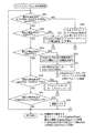
以上が再生装置の内部構成である。続いて制御部20及びグラフィクスデコーダ12を、どのようにして実装するかについて説明する。制御部20は、図31の処理手順を行うプログラムを作成し、汎用CPUに実行させることにより実装可能である。以降、図31を参照しながら、制御部20の処理手順について説明する。
図31は、機能セグメントのロード処理の処理手順を示すフローチャートである。本フローチャートにおいてSegmentKとは、AVClipの再生時において、読み出されたSegment(PCS,WDS,PDS,ODS)のそれぞれを意味する変数であり、無視フラグは、このSegmentKを無視するかロードするかを切り換えるフラグである。本フローチャートは、無視フラグを0に初期化した上で、ステップS21〜S24、ステップS27〜S31の処理を全てのSegmentKについて繰り返すループ構造を有している(ステップS25、ステップS26)。
【0127】
ステップS21は、SegmentKがPCSであるか否かの判定であり、もしSegmentKがPCSであれば、ステップS27、ステップS28の判定を行う。
ステップS22は、無視フラグが1かどうかの判定である。無視フラグが0であるならステップS23に移行し、1であるならステップS24に移行する。無視フラグが1であれば(ステップS22でYes)、ステップS23においてSegmentKをCoded Data Buffer13にロードする。
【0128】
無視フラグが0に設定されていれば(ステップS22がNo)、ステップS24においてSegmentKが無視される。これによりDSに属する機能セグメントは全て、ステップS22がNoになって、無視されることになる(ステップS24)。
このように、SegmentKが無視されるか、ロードされるかは、無視フラグの設定により決まる。ステップS27〜S31、S34、S35は、この無視フラグを設定する処理である。
【0129】
ステップS27は、PCSにおけるComposition_stateがAcquisition Pointであるか否かの判定である。SegmentKがAcquisition Pointであるなら、ステップS28に移行し、SegmentKがもしEpoch StartかNormal Caseであるなら、ステップS31に移行する。
ステップS28は、先行するDSがグラフィクスデコーダ12内のどれかのバッファ(Coded Data Buffer13、Stream Graphicsプロセッサ14、Object Buffer15、Composition Buffer16)に存在するかどうかの判定であり、ステップS27がYesである場合に実行される。グラフィクスデコーダ12内にDSが存在しないケースとは、頭出しがなされたケースをいう。この場合、Acquisition PointたるDSから、表示を開始せねばならないので、ステップS30に移行する(ステップS28でNo)。
【0130】
ステップS30は、無視フラグを0に設定し、ステップS22に移行する。
グラフィクスデコーダ12内にDSが存在するケースとは、通常再生がなされたケースをいう。この場合、ステップS29に移行する(ステップS28でYes)。ステップS29は、無視フラグを1に設定し、ステップS22に移行する。
ステップS31は、PCSにおけるComposition_stateがNormal Caseであるか否かの判定である。もしNormal Caseであるなら、ステップS34に移行する。SegmentKがEpoch Startであるなら、ステップS30において無視フラグを0に設定する。 ステップS34は、ステップS28と同じであり、先行するDSがグラフィクスデコーダ12内に存在するかどうかの判定を行う。もし存在するなら、無視フラグを0に設定する(ステップS30)。存在しないなら、元々、対話画面を構成する充分な機能セグメントが得られないため、無視フラグを1に設定する(ステップS35)。かかるフラグ設定により、先行するDSがグラフィクスデコーダ12に存在しない場合、Normal Caseを構成する機能セグメントは無視されることになる。
【0131】
DSが、図32のように多重化されている場合を想定して、DSの読み出しがどのように行われるかを説明する。図32の一例では、3つのDSが動画と多重化されている。この3つのDSのうち、初めのDS1は、Composition_stateがEpoch_Start、DS10はAcquisition Point、DS20は、Normal Caseである。
かかる3つのDSが、動画と多重化されているAVClipにおいて、ピクチャデータpt10からの頭出しが矢印am1に示すように行われたものとする。この場合、頭出し位置に最も近いDS10が、図31のフローチャートの対象となる。ステップS27においてComposition_stateはAcquisition Pointと判定されるが、先行するDSはCoded Data Buffer13上に存在しないため、無視フラグは0に設定され、このDS10が図33の矢印md1に示すように再生装置のCoded Data Buffer13にロードされる。一方、頭出し位置がDS10の存在位置より後である場合(図32の矢印am2)、DS20は、Normal CaseのDisplay Setであり、先行するDS20はCoded Data Buffer13に存在しないので、このDisplay Setは、無視されることになる(図33の矢印md2)。
【0132】
図34のように通常再生が行われた場合のDS1,10,20のロードは、図34に示すものとなる。3つのDSのうち、PCSのComposition_stateがEpoch StartであるDS1は、そのままCoded Data Buffer13にロードされるが(ステップS23)、PCSのComposition_stateがAcquisition PointであるDS10については、無視フラグが1に設定されるため(ステップS29)、これを構成する機能セグメントはCoded Data Buffer13にロードされず無視される(図35の矢印rd2,ステップS24)。またDS20については、PCSのComposition_stateはNormal Caseなので、Coded Data Buffer13にロードされる(図35の矢印rd3)。
【0133】
続いてGraphical Controller17の処理手順について説明する。図36〜図38は、Graphical Controller17の処理手順を示すフローチャートである。
ステップS41〜ステップS44は、本フローチャートのメインルーチンであり、ステップS41〜ステップS44に規定した何れかの事象の成立を待つ。
ステップS41は、現在の再生時点がPCSのPTS時刻になっているか否かの判定であり、もしなっていれば、ステップS45〜ステップS53の処理を行う。
【0134】
ステップS45は、PCSのcomposition_stateが、Epoch_Startであるか否かの判定であり、もしEpoch Startであるなら、ステップS46においてグラフィクスプレーン8を全クリアする。それ以外であるなら、ステップS47においてWDSのwindow_horizontal_position、window_vertival_position、window_width、window_heightに示されるwindowをクリアする。
【0135】
ステップS48は、ステップS46又はステップS47でのクリア後の実行されるステップであり、任意のODSxのPTS時刻が既に経過しているか否かの判定である。つまり、グラフィクスプレーン8全体のクリアにあたっては、そのクリア時間に長時間を費するので、あるODS(ODSx)のデコードが既に完了していることもある。ステップS48はその可能性を検証している。もし経過していないなら、メインルーチンにリターンする。どれかのODSのデコード時刻を経過しているなら、ステップS49〜ステップS51を実行する。ステップS49は、object_crop_flagが0を示しているか否かの判定であり、もし0を示しているなら、グラフィクスオブジェクトを非表示とする(ステップS50)。
【0136】
もし0を示していないなら、object_cropping_horizontal_position、object_cropping_vertival_position、cropping_width、cropping_heightに基づきクロップされたグラフィクスオブジェクトを、グラフィクスプレーン8のwindowにおいて object_cropping_horizontal_position,object_cropping_vertival_positionに示される位置に書き込む(ステップS51)。以上の処理により、ウィンドゥに1つ以上のグラフィクスオブジェクトが描かれることになる。
【0137】
ステップS52は、別のODSyのPTS時刻が経過しているか否かの判定である。ODSxをグラフィクスプレーン8に書き込んでいる際、別のODSのデコードが既に完了していれば、このODSyをODSxにして(ステップS53)、ステップS49に移行する。これにより、別のODSに対しても、ステップS49〜S51の処理が繰り返し行われる。
次に図37を参照して、ステップS42、ステップS54〜ステップS59について説明する。
【0138】
ステップS42は、現在の再生時点がWDSのPTSであるか否かの判定であり、もしWDSのPTSであるなら、ステップS54においてウィンドゥが1つであるか否かを判定し、もし2つであれば、メインルーチンにリターンする。ウィンドゥが1つであるなら、ステップS55〜ステップS59のループ処理を行う。このループ処理は、ウィンドゥに表示される2つのグラフィクスオブジェクトのそれぞれについて、ステップS57〜ステップS59を実行するというものである。ステップS57は、object_crop_flagが0を示しているか否かの判定であり、もし0を示しているなら、グラフィクスオブジェクトを非表示とする(ステップS58)。
【0139】
もし0を示していないなら、object_cropping_horizontal_position、object_cropping_vertival_position、cropping_width、cropping_heightに基づきクロップされたグラフィクスオブジェクトを、グラフィクスプレーン8のwindowにおいて object_cropping_horizontal_position,object_cropping_vertival_positionに示される位置に書き込む(ステップS59)。以上の処理を繰り返せば、ウィンドゥに1つ以上のグラフィクスオブジェクトが描かれることになる。
【0140】
ステップS44は、現在の再生時点がPCSのPTSに示される時点であるかの判定であり、もしそうであるなら、ステップS60においてPallet_update_flagが1を示しているか否かを判定する。もし1を示しているなら、pallet_idに示されるPDSをCLUT部に設定する(ステップS61)。0を示しているなら、ステップS61をスキップする。
その後、グラフィクスプレーン8におけるグラフィクスオブジェクトの色変換をCLUT部に行わせて、動画像と合成する(ステップS62)。
【0141】
次に図38を参照して、ステップS43、ステップS64〜ステップS66について説明する。
ステップS43は、現在の再生時点がODSのPTSであるか否かの判定であり、もしODSのPTSであるなら、ステップS63においてウィンドゥが2つであるか否かを判定し、もし1つであれば、メインルーチンにリターンする。ウィンドゥが2つであるなら、ステップS64〜ステップS66を行う。ステップS64は、object_crop_flagが0を示しているか否かの判定であり、もし示しているなら、グラフィクスオブジェクトを非表示とする(ステップS65)。
【0142】
もし0を示していないなら、object_cropping_horizontal_position、object_cropping_vertival_position、cropping_width、cropping_heightに基づきクロップされたグラフィクスオブジェクトを、グラフィクスプレーン8のwindowにおいて object_cropping_horizontal_position,object_cropping_vertival_positionに示される位置に書き込む(ステップS66)。以上の処理を繰り返せば、各ウィンドゥにグラフィクスオブジェクトが描かれることになる。
【0143】
以上、DSnに属するPCSのDTS,PTS,ODSのDTS、PTSの設定について説明したが、PDSのDTS、PTS、ENDのDTS、PTSについては説明していない。先ず、DSnに属する各PDSのDTS,PTSの設定について説明する。
DSnに属する各PDSは、PCSがComposition Buffer16にロードされる時点(DTS(DSn[PCS]))から、最初のODSのデコード開始時点(DTS(DSn[ODS1]))までに、CLUT部9において、有効になればよい。このことからDSnに属する各PDS(PDS1〜PDSlast)のPTS値は、以下の関係を満たす値に、設定されねばならない。
DTS(DSn[PCS])≦PTS(DSn[PDS1])
PTS(DSn[PDSj])≦PTS(DSn[PDSj+1])≦PTS(DSn[PDSlast])
PTS(DSn[PDSlast])≦DTS(DSn[ODS1])
尚、PDSにおいてDTSは再生時に参照されないが、MPEG2規格を満たすため、PDSのDTSは、そのPTSと同じ値に設定される。
以上の関係を満たすようDTS、PDSが設定された場合、再生装置のパイプラインにおいてこれらDTS、PTSがどのような役割をもつかについて説明する。図39はPDSにおけるPTSに基づく、再生装置におけるパイプラインを示す図である。この図39は、図28をベースにして作図されている。図39において第1段目は、CLUT部9へのPDS設定を示している。以降の段は、図28の第1〜第5段目と同じである。PDS1〜lastのCLUT部9への設定は、ODS1のデコード開始と同時になされる(矢印up2,up3)。
【0144】
続いてDSnに属するEND of Display SetSegmentのPTSの設定について説明する。DSnに属するENDは、DSnの終わりを示すものだから、ODS2のデコード終了時刻を示せばよい。このデコード終了時刻は、ODS2(ODSlast)のPTS(PTS(DSn[ODSlast]))に示されているので、ENDのPTSは、以下の式に示される値に設定されねばならない。
PTS(DSn[END]) = PTS(DSn[ODSlast])
DSn,DSn+1に属するPCSとの関係で考えれば、DSnにおけるPCSは、最初のODS(ODS1)のロード時刻以前に、Composition Buffer16にロードされるから、ENDのPTSは、DSnに属するPCSのロード時刻(DTS(DSn[PCS]))以降、DSn+1に属するPCSのロード時刻(DTS(DSn+1[PCS]))以前でなければならない。そのためENDのPTSは、以下の式の関係を満たす必要がある。
DTS(DSn[PCS])≦PTS(DSn[END])≦DTS(DSn+1[PCS])
一方、最初のODS(ODS1)のロード時刻は、最後のPDS(PDSlast)のロード時刻以前であるから、ENDのPTS(PTS(DSn[END]))は、DSnに属するPDSのロード時刻以降(PTS(DSn[PDSlast]))でなければならない。そのためENDのPTSは、以下の式の関係を満たす必要がある。
PTS(DSn[PDSlast])≦PTS(DSn[END])
続いて再生装置のパイプラインにおいて、ENDのPTSが、どのような意味合いをなすのかについて説明する。図40は、再生装置のパイプライン動作時における、ENDの意味合いを示す図である。本図は、図28の第2段目以降をベースに作図しており、第2段以降の意味合いは図28と同一である。また本図では、DSn,DSn+1という2つのDisplay Setを描いている。DSnにおいてODSlastになるのは、A-ODSsの最後のODSnであるので、ENDのPTSは、このODSnのPTSを示すよう設定されている。そして、このENDのPTSに示される時点は、DSn+1のPCSのDTSにより示される時点より早いものになっている。
【0145】
このENDのPTSにより、再生時にあたっては、DSnについてのODSのロードが、どの時点で完了するのかを知得することができる。
尚、ENDにおいてDTSは再生時に参照されないが、MPEG2規格を満たすため、PDSのDTSは、そのPTSと同じ値に設定される。
以上のように本実施形態によれば、グラフィックスプレーンの一部をグラフィクスの表示のためのウィンドゥとして指定するので、再生装置は、プレーン全体のグラフィクス描画を行う必要はない。グラフィックスプレーンの25%〜33%など、ある限られた大きさのウィンドゥに対してのみ、グラフィクス描画を行えばよい。グラフィックスプレーンのうち、ウィンドゥ以外の部分の描画を省くことができるので、再生装置側のソフトウェアの負担は遥かに軽くなる。
【0146】
グラフィックスプレーンの1/4等、グラフィクスのアップデートがワーストケースで行われる場合であっても、ピクチャとの同期が保証されるような大きさにウィンドゥを定めておけば、再生装置は、256Mbps等、ある決まった転送レートでグラフィックスプレーンの書き込みを行いさえすれば、ピクチャとの同期を実現することができる。
同期保証が容易になるので、高い解像度での字幕表示を多くの再生装置において実現することができる。
【0147】
(第2実施形態)
第1実施形態は、専ら、字幕として表示されるためのグラフィクスについて説明した。これに対し第2実施形態は、対話的に表示されるグラフィクスについての実施形態する。
本発明に係る記録媒体の実施行為のうち、生産行為についての形態について説明する。第2実施形態に係る記録媒体も、第1実施形態同様、BD-ROMの応用層に対する改良により実施することができる。図41は、第2実施形態に係るAVClipがどのように構成されているかを模式的に示す図である。
【0148】
AVClipは(中段)、複数のビデオフレーム(ピクチャpj1,2,3)からなるビデオストリーム、複数のオーディオフレームからなるオーディオストリームを(上1段目)、PESパケット列に変換し(上2段目)、更にTSパケットに変換し(上3段目)、同じくインタラクティブグラフィクスストリーム(下1段目)を、PESパケット列に変換し(下2段目)、更にTSパケットに変換して(下3段目)、これらを多重化することで構成される。
【0149】
続いてインタラクティブグラフィクスストリームについて説明する。インタラクティブグラフィクスストリームには、PCSの代わりにICS(Interactive Composition Segment)があり、WDSは存在しない。PDS(Palette Difinition Segment)、ODS(Object_Definition_Segment)、END(END of Display Set Segment)と呼ばれる機能セグメントが存在する点は、プレゼンテーショングラフィクスストリームと同じである。
【0150】
これらの機能セグメントにより定義される対話画面は、画面上にGUI部品を配置することにより作成される対話画面である。図42(a)は、インタラクティブグラフィクスストリームにより実現される対話画面を示す図である。この対話画面は、ボタンA〜ボタンDという4つのGUI部品を含む。インタラクティブグラフィクスストリームによる対話性とは、これらのGUI部品(ボタン)の状態をユーザ操作に応じて変化させることをいう。GUI部品(ボタン)における状態には、図42(a)に示すノーマル状態bt1、セレクテッド状態bt2、アクティブ状態bt3といったものがある。ノーマル状態とは、単に表示されているに過ぎない状態である。これに対しセレクテッド状態とは、ユーザ操作によりフォーカスが当てられているが、確定に至っていない状態をいう。アクティブ状態とは、確定に至った状態をいう。これらのボタンの状態は、第1実施形態に示したリモコン400のキーの押下により、変化させることができる。
【0151】
図42(b)は、対話画面に対する操作をユーザから受け付けるためのリモコン400におけるキーを示す図である。本図に示すようにリモコン400は、MoveUpキー、MoveDownキー、MoveRightキー、MoveLeftキーが設けられている。
MoveUpキーは、対話画面においてあるボタンがセレクテッド状態である場合、このボタンより上にあるボタンをセレクテッド状態に設定するためのキーである。MoveDownキーは、このボタンより下にあるボタンをセレクテッド状態に設定するためのキー、MoveRightキーは、このボタンより右にあるボタンをセレクテッド状態に設定するためのキー、MoveLeftキーは、このボタンより左にあるボタンをセレクテッド状態に設定するためのキーである。
【0152】
Activatedキーは、セレクテッド状態にあるボタンをアクティブ状態(アクティベート)するためのキーである。「0」〜「9」の数値キーは、該当する数値が割り当てられたボタンをセレクテッド状態にするキーである。「+10」キーとは、これまで入力された数値に10をプラスするという操作を受け付けるキーである。尚、「0」キー、「+10」キーは、何れも2桁以上の数値の入力を受け付けるものなので、「0」キー、「+10」キーは、どちらかが具備されていればよい。
【0153】
ノーマル状態、セレクテッド状態、アクティブ状態といった各状態は、複数の非圧縮状態のグラフィクスから構成される。ボタンの各状態を表現する個々の非圧縮グラフィクスを”グラフィクスオブジェクト”という。あるボタンの1つの状態を、複数の非圧縮グラフィクスで表現しているのは、各ボタンの1つの状態をアニメーション表示することを念頭に置いているからである。
【0154】
以上が本実施形態が想定している対話画面についての説明である。続いて本実施形態におけるDefinition Segment(ODS、PDS)の改良について説明する。ODS、PDSは、第1実施形態と同様のデータ構造を有している。差違は、ODSについての『object_ID』にある。第2実施形態におけるODSは、複数ODSにより定義される複数グラフィックスオブジェクトを用いてアニメーションを構成する。そしてアニメーションを構成するにあたって、一連のODSに、連番たる『object_ID』を付加する。以上がODS、PDSについての説明である。
【0155】
続いてICSについて説明する。Interactive Composition Segmentは、対話的な画面を構成する機能セグメントである。Interactive Composition Segmentは、図43に示すデータ構造で構成される。本図に示すようにICSは、『segment_type』と、『segment_length』と、『composition_number』と、『composition_state』と、『command_update_flag』と、『Composition_timeout_PTS』と、『Selection_timeout_PTS』と、『UO_Mask_Table』と、『animation_frame_rate_code』と、『default_selected_button_number』と、『default_activated_button_number』と、『ボタン情報群(button info(1)(2)(3)・・・・)』とからなる。
【0156】
『Composition_Number』は、ICSが属するDSにおいて、Updateがなされることを示す0から15までの数値である。
『composition_state』は、本ICSから始まるDSが、Normal Caseであるか、Acquisition Pointであるか、Epoch Startであるかを示す。
『command_update_flag』は、本ICS内のボタンコマンドは、前のICSから変化しているかを否かを示す。例えば、あるICSが属するDSが、Acquisition Pointであれば、このICSは、原則1つ前のICSと同じ内容になる。しかしcommand_update_flagをオンに設定しておけば、1つ前のICSと違うボタンコマンドをICSに設定しておくことができる。本フラグは、グラフィックスオブジェクトは流用するが、コマンドは変更したい場合に有効となる。
【0157】
『Composition_timeout_PTS』は、ボタンによる対話画面の終了時刻を記述する。終了時刻において対話画面の表示は、もはや有効ではなく表示されない。Composition_timeout_PTSは、動画データにおける再生時間軸の時間精度で記述しておくことが好ましい。
『Selection_Time_out_PTS』は、有効なボタン選択期間の終了時点を記述する。Selection_Time_out_PTSの時点において、Default_activated_button_numberにより特定されるボタンがアクティベートされる。Selection_Time_out_PTSは、Composition_timeout_PTSの時間と等しいかそれより短い。Selection_Time_out_PTSはビデオフレームの時間精度で記述される。
【0158】
『UO_Mask_Table』は、ICSに対応するDisplay Setにおけるユーザ操作の許可/不許可を示す。このマスクフィールドが不許可に設定されていれば、再生装置に対するユーザ操作は無効になる。
『animation_frame_rate_code』は、アニメーション型ボタンに適用すべきフレームレートを記述する。アニメーションフレームレートは、本フィールドの値を用いて、ビデオフレームレートを割ることにより与えられる。本フィールドが00なら、各ボタンのグラフィクスオブジェクトを定義するODSのうち、Start_Object_id_xxxにて特定されるもののみが表示され、アニメーションされない。
【0159】
『default_selected_button_number』は、対話画面の表示が始まったとき、デフォルトとしてセレクテッド状態に設定すべきボタン番号を指示する。本フィールドが”0”であれば、再生装置のレジスタに格納されたボタン番号のボタンが自動的にアクティブ状態に設定される。もしこのフィールドが非ゼロであれば、このフィールドは、有効なボタンの値を意味する。
【0160】
『default_activated_button_number』は、Selection_Time_out_PTSにより定義された時間の前に、ユーザがどのボタンもアクティブ状態にしなかったとき、自動的にアクティブ状態に設定されるボタンを示す。default_activated_button_numberが”FF”であれば、Selection_Time_out_PTSにより定義される時刻において、現在セレクテッド状態にあるボタンが自動的に選択される。このdefault_activated_button_numberが00であれば、自動選択はなされない。00,FF以外の値であれば本フィールドは、有効なボタン番号として解釈される。
【0161】
『ボタン情報(Button_info)』は、対話画面において合成される各ボタンを定義する情報である。図中の引き出し線hp1はICSにより制御されるi番目のボタンについてのボタン情報iの内部構成をクローズアップしている。以降、ボタン情報iを構成する情報要素について説明する。
『button_number』は、ボタンiを、ICSにおいて一意に識別する数値である。
【0162】
『numerically_selectable_flag』は、ボタンiの数値選択を許可するか否かを示すフラグである。
『auto_action_flag』は、ボタンiを自動的にアクティブ状態にするかどうかを示す。auto_action_flagがオン(ビット値1)に設定されれば、ボタンiは、セレクテッド状態になる代わりにアクティブ状態になる。auto_action_flagがオフ(ビット値0)に設定されれば、ボタンiは、選択されたとしてもセレクテッド状態になるにすぎない。
【0163】
『object_horizontal_position』、『object_vertical_position』は、対話画面におけるボタンiの左上画素の水平位置、垂直位置を示す。
『upper_button_number』は、ボタンiがセレクテッド状態である場合においてMOVEUPキーが押下された場合、ボタンiの代わりに、セレクテッド状態にすべきボタンの番号を示す。もしこのフィールドにボタンiの番号が設定されていれば、MOVEUPキーの押下は無視される。
【0164】
『lower_button_number』,『left_button_number』,『right_button_number』は、ボタンiがセレクテッド状態である場合においてMOVE Down キー,MOVE Left キー,MOVE Right キーが押下された場合、ボタンiの押下の代わりに、セレクテッド状態にすべきボタンの番号を示す。もしこのフィールドにボタンiの番号が設定されていれば、これらのキーの押下は無視される。
【0165】
『start_object_id_normal』は、ノーマル状態のボタンiをアニメーションで描画する場合、アニメーションを構成する複数ODSに付加された連番のうち、最初の番号がこのstart_object_id_normalに記述される。
『end_object_id_normal』は、ノーマル状態のボタンiをアニメーションで描画する場合、アニメーションを構成する複数ODSに付加された連番たる『object_ID』のうち、最後の番号がこのend_object_id_normalに記述される。このEnd_object_id_normalに示されるIDが、start_object_id_normalに示されるIDと同じである場合、このIDにて示されるグラフィックスオブジェクトの静止画が、ボタンiの絵柄になる。
【0166】
『repeated_normal_flag』は、ノーマル状態にあるボタンiのアニメーション表示を反復継続させるかどうかを示す。
『start_object_id_selected』は、セレクテッド状態のボタンiをアニメーションで描画する場合、アニメーションを構成する複数ODSに付加された連番のうち、最初の番号がこのstart_object_id_selectedに記述される。
【0167】
『end_object_id_selected』は、セレクト状態のボタンをアニメーションで描画する場合、アニメーションを構成する複数ODSに付加された連番たる『object_ID』のうち、最後の番号がこのend_object_id_selectedに記述される。
このEnd_object_id_selectedに示されるIDが、start_object_id_selectdに示されるIDと同じである場合、このIDにて示されるグラフィックスオブジェクトの静止画が、ボタンiの絵柄になる。
【0168】
『repeat_selected_flag』は、セレクテッド状態にあるボタンiのアニメーション表示を、反復継続するかどうかを示す。start_object_id_selectedと、end_object_id_selectedとが同じ値になるなら、本フィールド00に設定される。
『start_object_id_activated』は、アクティブ状態のボタンiをアニメーションで描画する場合、アニメーションを構成する複数ODSに付加された連番のうち、最初の番号がこのstart_object_id_activatedに記述される。
【0169】
『end_object_id_activated』は、アクティブ状態のボタンをアニメーションで描画する場合、アニメーションを構成する複数ODSに付加された連番たる『object_ID』のうち、最後の番号がこのend_object_id_activatedに記述される。
続いてボタンコマンドについて説明する。
『ボタンコマンド(button_command)』は、ボタンiがアクティブ状態になれば、実行されるコマンドである。
【0170】
以上がICSの内部構成である。ICSによる対話制御の具体例について以下説明する。本具体例は、図44のようなODS、ICSを想定している。図44は、あるDSnに含まれるODSと、ICSとの関係を示す図である。このDSnには、ODS11〜19,21〜29,31〜39,41〜49が含まれているものとする。これらのODSのうち、ODS11〜19は、ボタンAの各状態を描いたものであり、ODS21〜29は、ボタンBの各状態を描いたもの、ODS31〜39は、ボタンCの各状態を描いたもの、ODS41〜49は、ボタンDの各状態を描いたものとする(図中の括弧}を参照)。そしてICSにおけるbutton_info(1),(2),(3),(4)にて、これらのボタンA〜ボタンDの状態制御が記述されているものとする(図中の矢印bh1,2,3,4参照)。
【0171】
このICSによる制御の実行タイミングが、図45に示す動画のうち、任意のピクチャデータpt1の表示タイミングであれば、ボタンA〜ボタンDからなる対話画面tm1が、このピクチャデータpt1に合成(gs1)されて表示されることになる(gs2)。動画の中身に併せて、複数ボタンからなる対話画面が表示されるので、ICSによりボタンを用いたリアルな演出が可能になる。
【0172】
図47に示すボタンA〜ボタンDの状態遷移を実行する場合のICSの記述例を図46に示す。図47における矢印hh1,hh2は、button info(1)のneighbor_info()による状態遷移を象徴的に表現している。button info(1)のneighbor_info()におけるlower_button_numberは、ボタンCに設定されているため、ボタンAがセレクテッド状態になっている状態で、MOVEDownキー押下のUOが発生すれば(図47のup1)、ボタンCがセレクテッド状態になる(図47のsj1)。button info(1)のneighbor_info()におけるright_button_numberは、ボタンBに設定されているため、ボタンAがセレクテッド状態になっている状態で、MOVERightキー押下のUOが発生すれば(図47のup2)、ボタンBがセレクテッド状態になる(図47のsj2)。
【0173】
図47における矢印hh3は、button info(3)のneighbor_info()による状態遷移の制御を示す。button info(3)のneighbor_info()におけるupper_button_numberは、ボタンAに設定されているため、ボタンCがセレクテッド状態になっている状態で(up3)、MOVEUpキー押下のUOが発生すれば、ボタンAがセレクテッド状態に戻る。
続いてボタンA〜ボタンDの絵柄について説明する。ODS11,21,31,41が図48に示す絵柄であるものとする。そしてボタンAに割り当てられたODS11〜19は、図49のような絵柄であるものとする。ICSにおけるbutton_info(1)のnormal_state_info()におけるstart_object_id_normal,end_object_id_normalは、ODS11〜13を指定しているため、ボタンAのノーマル状態は、ODS11〜13によるアニメーションで表現される。またbutton_info(1)のselected_state_info()におけるstart_object_id_selected,end_object_id_selectedは、ODS14〜16を指定しているため、ボタンAのセレクテッド状態は、ODS14〜16で表現される。ユーザがこのボタンAをセレクテッド状態にすることにより、ボタンAの絵柄たる肖像は、ODS11〜13によるものから、ODS14〜16によるものへと変化する。ここでnormal_state_info()、selected_state_info()におけるrepeat_normal_flag,repeat_select_flagを1にしておけば、ODS11〜13によるアニメーション、ODS14〜16によるアニメーションは、図中の「→(A)」,「(A)→」,「→(B)」,「(B)→」,に示すように、アニメーション表示は反復継続する。
【0174】
アニメーション描画が可能な複数ODSが、ボタンA〜ボタンDに割り当てられており、これらによる制御がICSに記述されていれば、ユーザ操作に併せてキャラクタの表情が変わるような、リアルなボタンの状態制御を実現することができる。
続いてDisplay SetにおけるODSの順序について説明する。Display Setに属するODSは、ボタンの1つの状態を表すようICSにて指定されていることは、上述した通りである。ODSは、こうした指定、つまり、ボタンのどの状態を示すかという指定に応じて、Display Setにおける順序が決められる。
【0175】
詳しくいうとDisplay SetにおいてODSは、ノーマル状態を表すもの(1)、セレクテッド状態を表すもの(2)、アクティブ状態を示すもの(3)というように、同じ状態を表すもの同士がグループ化される。このボタンの1つの状態を表すグループをbutton-stateグループという。そしてこれらbutton-stateグループを、ノーマル状態→セレクテッド状態→アクティブ状態というように並べる。このようにボタンのどの状態を表すかに応じて、ODSの順序を決めるというのが、Display SetにおけるODSの順序である。
【0176】
図50は、Display Setに属するODSの順序を示す図である。本図の第2段目に、Display Setにおける3つのbutton-stateグループを示す。本図においてノーマル状態を描くODSの集合(ODSs for Normal state)、ボタンのセレクテッド状態を描くODSの集合(ODSs for Selected state)、ボタンのアクティブ状態を描くODSの集合(ODSs for Actioned state)が示されている。そしてこれらbutton-stateグループの順序は、ノーマル状態→セレクテッド状態→アクティブ状態というように並べられている。これはODSのうち、対話画面の初期表示を構成するものを早く読み出させ、アップデート後の画面表示を構成するものの読み出しを後にするという配慮である。
【0177】
図50の第1段目は、これらbutton-stateグループにより描かれるグラフィクスオブジェクトAn,Bn,Cn,Dn,As,Bs,Cs,Ds,Aa,Ba,Ca,Daを示す。本図におけるAn,Bn,Cn,Dnにおける添字nは各ボタンのノーマル状態を表し、As,Bs,Cs,Dsにおける添字sは各ボタンのセレクテッド状態を表す。Aa,Ba,Ca,Daにおける添字aは各ボタンのアクティブ状態を表す。図50の第2段目は、第1段目のグラフィクスオブジェクトが属するbutton-stateグループを示す。尚、本図におけるODS1〜ODSnという表記は、「1」,「n」というような同じ番号が付されているが、これらN-ODSs,S-ODSs,A-ODSsに属するODSは別々のものである。以降、同様の表記の図は同じ意味であるとする。
【0178】
図51は、図50のbutton-stateグループが配置された対話画面における状態遷移を示す図である。
本図における対話画面は、”初期表示”、”1stユーザアクションによる更新表示”、”2ndユーザアクションによる更新表示”という複数の状態をもつ。図中の矢印は、状態遷移のトリガとなるユーザアクションを表す。この図を参照すると、4つのボタンA,B,C,Dはそれぞれノーマル状態、セレクテッド状態、アクティブ状態という状態をもっている。このうち初期表示に必要なのは、3つのノーマル状態を描くグラフィクスオブジェクトと、1つのセレクテッド状態を描くグラフィクスオブジェクトであることがわかる。
【0179】
デフォルトセレクテッドボタンが未確定であり、ボタンA〜ボタンDのうち、どのボタンがセレクテッド状態になるかが動的に変わる場合であっても、各ボタンのノーマル状態、セレクテッド状態を表すグラフィクスオブジェクトのデコードが完了すれば、初期表示を実現することができる。このことを意識して、本実施形態では、各状態に対応するbutton-stateグループを、図50の第2段目に示すようにノーマル状態→セレクテッド状態→アクティブ状態の順に配列している。かかる配列により、アクティブ状態を構成するODSの読み出しやデコードが未完であっても、初期表示を実現することができ、Display Setの読み出し開始から初期表示の完了までの期間を短くすることができる。
【0180】
続いて図48、図49に示したODSを、どのような順序で配列させるかについて説明する。図52は、Display SetにおけるODSの順序を示す図である。本図においてODSs for Normal stateは、ODS11〜13,ODS21〜23,ODS31〜33,ODS41〜43から構成されている。またODSs for Selected stateは、ODS14〜16,ODS24〜26,ODS34〜36,ODS44〜46から構成され、ODSs for Actioned stateは、ODS17〜19,ODS27〜29,ODS37〜39,ODS47〜49から構成されている。ODS11〜13は、図49に示したような、キャラクターの表情変化を描くものであり、ODS21〜23,ODS31〜33,ODS41〜43も同様なので、これらのODSを先頭のbutton-stateグループに配置することにより、Display Setの読み出しの途中であっても、初期表示の準備を整えることができる。これによりアニメーションを取り入れた対話画面を、遅滞なく実行することができる。
【0181】
続いて複数のボタン状態からの多重参照されるODSの順序について説明する。多重参照とは、あるODSについてのobject_idがICSにおける2以上のnormal_state_info,selected_state_info,activated_state_infoにより指定されていることをいう。かかる多重参照を行えば、あるボタンのノーマル状態を描くグラフィクスオブジェクトを用いて、他のボタンのセレクテッド状態を描くことができ、グラフィクスオブジェクトの絵柄を共用することができる。かかる共用により、ODSの数を少なくすることができる。多重参照されるODSについては、どのbutton-stateグループに属するかが問題になる。
【0182】
つまりあるボタンのノーマル状態と、別のボタンのセレクテッド状態とが1つのODSで描かれている場合、このODSは、ノーマル状態に対応するbutton-stateグループに属するか、セレクテッド状態に対応するbutton-stateグループに属するかが問題となる。
この場合ODSは、複数状態のうち、最も早く出現する状態に対応するbutton-stateグループだけ1回のみ配置される。
【0183】
あるODSがノーマル状態、セレクテッド状態で多重参照されるなら、ノーマル状態に対応するbutton-stateグループ(N-ODSs)にこのODSは配置され、セレクテッド状態に対応するbutton-stateグループ(S-ODSs)には配置されない。また別のODSがセレクテッド状態、アクティブ状態で多重参照されるなら、セレクテッド状態に対応するbutton-stateグループ(S-ODSs)にこのODSは配置され、アクティブ状態に対応するbutton-stateグループ(A-ODSs)には配置されない。このように多重参照されるODSは、最も早く出現する状態に対応するbutton-stateグループ内に一回だけ配置される。以上が多重参照されるODSの順序についての説明である。
【0184】
S-ODSsにおける、ODSの順序について説明する。S-ODSsにおいて、どのODSが先頭に位置するかは、デフォルトセレクテッドボタンが静的に確定しているか、動的であるかによって違う。静的に確定したデフォルトセレクテッドボタンとは、ICSにおけるdefault_selected_button_numberに00以外の有効な値が設定され、この値で指示されるボタンのことをいう。default_selected_button_numberが有効な値を示しており、尚且つデフォルトセレクテッドボタンを表すODSが、N-ODSsに無い場合は、デフォルトセレクテッドボタンを表すODSが、S-ODSsの先頭に配置される。
【0185】
default_selected_button_numberが値00を示している場合、デフォルトでセレクテッド状態に設定されるボタンは、再生装置側の状態によって動的に変化する。
値0を示すよう、default_selected_button_numberを設定しておくのは、例えば、Display Setが多重されているAVClipが、複数再生経路の合流点になっているようなケースである。先行する複数再生経路がそれぞれ第1、第2、第3章であり、合流点にあたるDisplay Setが第1章、第2章、第3章に対応するボタンを表示させるものである場合、default_selected_button_numberにおいて、デフォルトでセレクテッド状態とすべきボタンを決めてしまうのは、おかしい。
【0186】
第1章からの到達時には第2章にあたるボタン、第2章からの到達時には第3章にあたるボタン、第3章からの到達時には第4章にあたるボタンというように、このDisplay Setに到達するまでに、先行する複数再生経路のうち、どの再生経路を経由するかによって、セレクテッド状態とすべきボタンを変化させるのが理想的である。先行する再生経路によって、セレクテッド状態とすべきボタンが変わるようなケースにおいて、default_selected_button_numberは無効を示すよう、0に設定される。どの再生経路を経由するかによって、セレクテッド状態とすべきボタンを変化するから、特定のODSをbutton-stateグループの先頭に配置するというような配慮は行わない。
【0187】
図53は、default_selected_button_numberが”=0”である場合と、”=ボタンB”である場合とでS-ODSsにおいてODSの並びがどのように変わるかを示す図である。本図において破線ss1は、default_selected_button_numberがボタンBを示している場合に、S-ODSsにおけるODSの配列がどのようになるかを示しており、破線ss2は、default_selected_button_numberが=0を示している場合に、S-ODSsにおけるODSの配列がどのようになるかを示している。この図の表記からもわかるように、default_selected_button_numberがボタンBを示している場合、ボタンBのセレクテッド状態を示すODSBsがS-ODSsの先頭に配され、その他のボタンのODSは、後回しにされている。一方、default_selected_button_numberが”=0”である場合、ボタンAのセレクテッド状態を表すODSAsが先頭に配置されている。このようにdefault_selected_button_numberが有効かどうかは、S-ODSs内の順序に大きな変動をもたらす。
【0188】
以上がODSの順序についての説明である。続いてこれらICS、ODSを有したDisplay Setが、AVClipの再生時間軸上にどのように割り当てられるかについて説明する。ODSについてのDTS、PTSは、第1実施形態に示した数式に基づき設定すればよい。ICSにおけるDTS、PTSは、第1実施形態に示したものとは違ったものになる。以降ICSの、DTS値、PTS値について説明する。
【0189】
ICSのPTSは、Epoch開始直後であればDSnの初期表示を構成するODSのうち、デコード時刻が最も遅いODSのPTS値(1)、グラフィクスプレーンのクリアに要する時間(2)、ODSのデコードにより得られたグラフィクスオブジェクトをグラフィクスプレーンに書き込む書込時間(3)を足した値以降に設定される。一方Acquisition Pointであれば、ODSのPTS値(1)にプレーン書込期間(3)を足した値(ODSのPTS値(1)+プレーン書込期間(3))以降に設定される。
【0190】
ICSにおいてdefault_selected_button_numberが指定されている場合は、全てのボタンのノーマル状態を描画するODSのデコードと、デフォルトボタンのセレクテッド状態を描画するODSのデコードさえ完了すれば、初期表示を行うことができる。初期表示における複数ボタンのセレクテッド状態を描画するODSを、S-ODSsと呼び、そのうちデコード時刻が最も早いもの(この場合、デフォルトボタンを描画するもの)をS-ODSsfirstと呼ぶ。このS-ODSsfirstのPTS値を、デコード時刻が最も遅いODSのPTS値として、ICSのPTSの基準に用いる。
【0191】
ICSにおいてdefault_selected_button_numberが指定されていない場合は、どのボタンがセレクテッド状態になるかわからないから、全ボタンのノーマル状態、セレクテッド状態を描画する準備が整なわないと、初期表示の準備が完了しない。初期表示における複数ボタンのセレクテッド状態を描画するS-ODSsのうち、デコード時刻が最も遅いものをS-ODSslastと呼ぶ。このS-ODSslastのPTS値を、デコード時刻が最も遅いODSのPTS値として、ICSのPTSの基準値に用いる。
【0192】
S-ODSsfirstのデコード終了時刻をPTS(DSn[S-ODSsfirst])とすると、PTS(DSn[ICS])は、PTS(DSn[S-ODSsfirst])に、グラフィクスプレーンのクリアに要する時間(2)、ODSのデコードにより得られたグラフィクスオブジェクトをグラフィクスプレーンに書き込む書込時間(3)を足した値になる。
グラフィックスプレーン内において描画可能な矩形領域の横幅をvideo_width,縦幅をvideo_heightとし、グラフィックスプレーンへの書込レートを128Mbpsとすると、グラフィックスプレーンのクリアに要する時間は、8×video_width×video_height//128,000,000と表現される。これを90KHzの時間精度で表現すれば、グラフィックスプレーンのクリア時間(2)は90,000×(8×video_width×video_height//128,000,000)になる。
【0193】
ICSに含まれる全ボタン情報により、指定されるグラフィックスオブジェクトの総サイズをΣSIZE(DSn[ICS.BUTTON[i]])とし、グラフィックスプレーンへの書込レートを128Mbpsとすると、グラフィックスプレーンへの書き込みに要する時間は、ΣSIZE(DSn[ICS.BUTTON[i]])//128,000,000と表現される。これを90KHzの時間精度で表現すれば、グラフィックスプレーンのクリア時間(2)は90,000×(ΣSIZE(DSn[ICS.BUTTON[i]])//128,000,000)になる。
【0194】
ここでΣSIZE(DSn[ICS.BUTTON[i]])は、各ボタンを表すグラフィクスオブジェクトのうち、最初に表示されるもののサイズの総和を意味する。このΣSIZE(DSn[ICS.BUTTON[i]])はデフォルトセレクテッドボタンが確定している場合と、動的に変わる場合とで、違う値になる。デフォルトセレクテッドボタンが静的に確定している場合、ΣSIZE(DSn[ICS.BUTTON[i]])は、デフォルトセレクテッドボタンのセレクテッド状態を表す複数ODSのうち最初に表示されるもの、デフォルトセレクテッドボタン以外のボタンのノーマル状態を表す複数ODSのうち、最初に表示されるものの総和になる。
【0195】
続いてデフォルトセレクテッドボタンが動的に変わる場合、どのボタンがデフォルトセレクテッドボタンになるかはわからないから、書き込み時間が最も長くなるケースを想定しせねばならない。ここで、任意のボタンxのノーマル状態における最初の一枚を表すグラフィクスオブジェクト(ODSn1)、及び、ボタンxのセレクテッド状態における最初の一枚を表すグラフィクスオブジェクト(ODSs1)のうち、サイズが大きいもの(Max(ODSn1,ODSs1))を、1つのボタンxにおいて最初に表示すべきグラフィクスオブジェクトと考える。
【0196】
このMax(ODSn1,ODSs1)を、全てのボタンについて足し合わせた結果が、ΣSIZE(DSn[ICS.BUTTON[i]])になる。
図54(a)(b)は、N-ODSsにボタンA〜Dを構成する複数ODSが含まれており、S-ODSsにボタンA〜Dを構成する複数ODSが含まれている場合、ΣSIZE(DSn[ICS.BUTTON[i]])がどのような値になるかを示す図である。ここでdefault_selected_button_numberが有効な値を示している場合、ΣSIZE(DSn[ICS.BUTTON[i]])は太い枠で示す4つのODSのサイズの総和となる。”As1”は、ボタンAのセレクテッド状態を表す複数のODSのうち最初に表示されるODSである。”Bn1”,”Cn1”,”Dn1”は、ボタンB〜ボタンDのノーマル状態を表す複数のODSのうち最初に表示されるODSを示す。これらのサイズをsize()で表すと、ΣSIZE(DSn[ICS.BUTTON[i]]) は、size(As1)+size(Bn1)+size(Cn1)+size(Dn1)になる。
【0197】
一方、default_selected_button_numberが”=0”であるなら、An1,As1のうち大きいODS、Bn1,Bs1のうち大きいODS、Cn1,Cs1のうち大きいODS、Dn1,Ds1のうち大きいODSの和がΣSIZE(DSn[ICS.BUTTON[i]])になる。
故にΣSIZE(DSn[ICS.BUTTON[i]])は、
ΣSIZE(DSn[ICS.BUTTON[i]])
= max(size(An1),size(As1))+max(size(Bn1),size(Bs1))
+max(size(Cn1),size(Cs1))+max(size(Dn1),size(Ds1))
になる。
以上の数式を用いることにより、Epoch Start開始直後のPTS(DSn[ICS])は、以下の数式のように表現される。
PTS(DSn[ICS])≧PTS(DSn[S-ODSsfirst])
+90,000×(8×video_width×video_height//128,000,000)
+90,000×(ΣSIZE(DSn[ICS.BUTTON[i]])//128,000,000)
一方、default_selected_button_numberが無効である場合、PTS(DSn[S-ODSsfirst])をPTS(DSn[S-ODSslast])に置き換えればよい。つまり算出式は、以下の通りになる。
PTS(DSn[ICS])≧PTS(DSn[S-ODSslast])
+90,000×(8×video_width×video_height//128,000,000)
+90,000×(ΣSIZE(DSn[ICS.BUTTON[i]])//128,000,000)
以上のようにしてPTS、DTSを設定することにより、同期表示を実現する場合の一例を図55に示す。本図において動画における任意のピクチャデータpy1の表示タイミングで、ボタンを表示させる場合を想定する。この場合、ICSのPTS値は、このピクチャデータの表示時点になるよう設定せねばならない。
【0198】
そしてICSのPTSから、画面のクリア期間cd1、グラフィクスオブジェクトの転送期間td1を差し引いた時刻に、DSnの初期表示を構成するODSのうち、デコード時刻が最も遅いODSのデコードが完了せねばならないから、図中の時点(1)に、ODSのPTS値が設定しなければならない。更に、ODSのデコードには期間dd1を要するから、このPTSより期間dd1だけ早い時点に、このODSのDTS値を設定せねばならない。
【0199】
図55において、動画と合成されるODSは1つだけであり、単純化されたケースを想定している。動画と合成されるべき対話画面の初期表示が、複数のODSで実現される場合、ICSのPTS及びDTS、ODSのPTS、DTSは図56のように設定せねばならない。
図56は、対話画面の初期表示が複数ODSにて構成され、デフォルトセレクテッドボタンが静的に確定している場合のDTS、PTSの設定を示す図である。初期表示を実現するODSのうち、デコードが最も遅いS-ODSsfirstのデコードが図中の期間dd1の経過時に終了するなら、このS-ODSsfirstのPTS(DSn[S-ODSsfirst])は、期間dd1の経過時を示すよう設定される。
【0200】
更に、初期表示の実現には、画面クリアを行い、デコードされたグラフィクスオブジェクトを転送せねばならないから、このPTS(DSn[S-ODSsfirst])の値に画面クリアに要する期間(90,000×(8×video_width×video_height//128,000,000))、デコードされたグラフィクスオブジェクトの転送期間(90,000×(ΣSIZE(DSn[ICS.BUTTON[i]])//128,000,000))を足した時点以降を、ICSのPTS(DSn[ICS])として設定せねばならない。
【0201】
図57は、対話画面の初期表示が複数ODSにて構成され、デフォルトセレクテッドボタンが未定である場合のDTS、PTSの設定を示す図である。初期表示を実現するS-ODSsのうち、デコードが最も遅いS-ODSslastのデコードが図中の期間dd2の経過時に終了するなら、このS-ODSslastのPTS(DSn[S-ODSslast])は、期間dd2の経過時を示すように設定される。
更に、初期表示の実現には、画面クリアを行い、デコードされたグラフィクスオブジェクトを転送せねばならないから、このPTS(DSn[S-ODSslast])の値に画面クリアに要する期間(90,000×(8×video_width×video_height//128,000,000))、デコードされたグラフィクスオブジェクトの転送期間(90,000×(ΣSIZE(DSn[ICS.BUTTON[i]])//128,000,000))を足した時点以降を、ICSのPTS(DSn[ICS])として設定せねばならない。以上がICSによる同期制御である。
【0202】
尚、ICSのPTSによる同期制御は、再生時間軸上のあるタイミングでボタンを表示するという制御のみならず、再生時間軸上のある期間でPopupメニューの表示を可能とする制御を含む。Popupメニューとは、リモコン400に設けられたメニューキーの押下でPopup表示されるメニューであり、このPopup表示が、AVClipにおけるあるピクチャデータの表示タイミングで可能になることも、ICSのPTSによる同期制御である。Popupメニューを構成するODSは、ボタンを構成するODSと同様、ODSのデコードが完了し、デコードにより得られたグラフィックスオブジェクトがグラフィックスプレーンに書き込まれる。このグラフィックスプレーンへの書き込みが完了していなければ、ユーザからのメニューコールに応ずることはできない。そこでPopupメニューの同期表示にあたって、ICSのPTSに、Popup表示が可能になる時刻を示しておくのである。
【0203】
以上が本発明に係る記録媒体の実施形態である。続いて本発明に係る再生装置の実施形態について説明する。第2実施形態に係る再生装置の内部構成は、第1実施形態に示したものと略同一になる。そしてこれらの構成において、Object Buffer15、Graphicalコントローラ17に改良が加えられている。以下、Object Buffer15、Graphicalコントローラ17の改良について説明する。
【0204】
第2実施形態に係るObject Buffer15には、Stream Graphicsプロセッサ14のデコードにより得られたグラフィクスオブジェクトであって、対話画面を構成するためのボタンが配置される。図58は、Object Buffer15の格納内容をグラフィクスプレーン8と対比して示す図である。この格納内容は、図48、図49に示した具体例のODSが、Object Buffer15に書き込まれる場合を想定している。図48、図49の具体例は、4つのボタンのアニメーションを、36個のODS(ODS11〜49)により実現するものであったが、このアニメーションの全てのコマを表すODSが、このObject Buffer15に格納される。一方グラフィクスプレーン8には、このObject Buffer15に格納された個々のODSの表示位置が規定されれる。この表示位置は、各ボタン情報のButton_horizontal_position、Button_vertical_positionにより定義されるものであり、Object Buffer15に格納されている複数ODSのそれぞれを、1コマずつ転送してグラフィクスプレーン8の表示位置に書き込んでゆくことにより、アニメーションは実現される。
【0205】
第2実施形態に係るGraphicsコントローラ17は、Compositionバッファ16に配置されたICSを解読して、ICSに基づく制御をする。この制御の実行タイミングは、ICSに付加されたPTSの値に基づく。このGraphicsコントローラ17のうち、重要なものは対話画面の初期表示時、更新時における書込処理である。以降、Graphicsコントローラ17による対話画面の初期表示時、更新時における書込処理を、図59を参照しながら説明する。図59は、初期表示時におけるGraphicsコントローラ17の処理を示す図である。本図に示すように、ボタンAにおけるボタン情報のButton_horizontal_position、Button_vertical_positionに規定される表示位置に、ボタンAのS-ODSsに属するODSを書き込み、ボタンB,C,Dにおけるボタン情報のButton_horizontal_position、Button_vertical_positionに規定される表示位置に、ボタンB,C,DのN-ODSsに属するODSを書き込むようGraphicsコントローラ17は制御を行う(図中の矢印w1,w2,w3,w4は、この書き込みを象徴的に示す)。この書き込みにより、図51に示した初期表示を作成することができる。ここで注目すべきは、対話画面の初期表示にあたっては、全てのODSが必要ではなく、デフォルトセレクテッドボタンのS-ODSsに属するODS、それ以外のボタンのN-ODSsに属するODSさえObject Buffer15に存在すれば、対話画面の初期表示は完了する点である。このことから、Object Buffer15に格納されるべき複数ODSのうち、デフォルトセレクテッドボタンのS-ODSsに属するODS、それ以外のボタンのN-ODSsに属するODSのデコードさえ完了すれば、Graphicsコントローラ17は対話画面の初期表示のための書き込みを開始することができる。
【0206】
図60は、1stUserAction(MoveRight)による対話画面更新時におけるGraphicsコントローラ17の処理を示す図である。本図に示すように、ボタンBのボタン情報におけるボタン情報のButton_horizontal_position、Button_vertical_positionに規定される表示位置に、ボタンBのS-ODSsに属するODSを書き込み、ボタンAのボタン情報におけるボタン情報のButton_horizontal_position、Button_vertical_positionに規定される表示位置に、ボタンAのN-ODSsに属するODSを書き込むようGraphicsコントローラ17は制御を行う(図中の矢印w5,w6,w7,w8は、この書き込みを象徴的に示す)。この書き込みにより、図51に示したような状態遷移を実現することができる。ボタンC,Dは対話画面の初期表示時と同じくノーマル状態のままであるが、アニメーションを継続するため、グラフィクスプレーン8への書き込みが継続してなされている。
【0207】
同じく、1stUserActionが、MoveDown,Activatedである場合の、対話画面更新時におけるGraphicsコントローラ17の処理を図61、図62に示す。対話画面更新にあたっては、デフォルトセレクテッドボタン以外のボタンについてのS-ODSsや、A-ODSsも必要になり、全てのODSがObject Buffer15に格納されていることが望まれる。以上がGraphicsコントローラ17の処理内容である。
【0208】
以上のように構成された再生装置において、各構成要素は第1実施形態同様、パイプライン式にデコード処理を行う。
図63は、再生装置によるパイプライン処理を示すタイミングチャートである。第4段目は、BD-ROMにおけるDisplay Setを示し、第3段目は、Coded Dataバッファ13へのICS、PDS、ODSの読出期間を示す。第2段目は、Stream Graphicsプロセッサ14による各ODSのデコード期間を示す。第1段目は、Graphicsコントローラ17による処理期間を示す。各ODSのデコード開始時刻は、図中のDTS11,DTS12,DTS13に示されている。Coded Dataバッファ13へのN-ODSsに属する最初のODS(N-ODSs[ODS1])の格納はDTS11までに完了し、Coded Dataバッファ13へのN-ODSsに属する最後のODS(N-ODSs[ODSn])の格納は、DTS12に示される時刻までに完了する。このように各ODSは、自身のDTSに示される時刻までにCoded Dataバッファ13への読み出しが完了している。
【0209】
一方、各ODSのデコード終了時刻は、図中のPTS11,PTS12,PTS13に示されている。Stream Graphicsプロセッサ14によるN-ODSs(ODS1)のデコードはPTS11までに完了し、N-ODSs(ODSn)のデコードは、PTS12に示される時刻までに完了する。以上のように、各ODSのDTSに示される時刻までに、ODSをCoded Dataバッファ13に読み出し、Coded Dataバッファ13に読み出されたODSを、各ODSのPTSに示される時刻までに、デコードしてObject Buffer15に書き込む。これらの処理を、1つのStream Graphicsプロセッサ14は、パイプライン式に行う。
【0210】
デフォルトセレクテッドボタンが静的に確定している場合、対話画面の初期表示に必要なグラフィクスオブジェクトがObject Buffer15上で全て揃うのは、ノーマル状態に対応するbutton-stateグループ、セレクテッド状態に対応するbutton-stateグループの先頭ODSのデコードが完了した時点である。本図でいえば、PTS13に示される時点で、対話画面の初期表示に必要なグラフィクスオブジェクトは全て揃う。
【0211】
本図の第1段目における期間cd1は、Graphicsコントローラ17がグラフィクスプレーン8をクリアするのに要する期間である。また期間td1は、Object Buffer15上にえられたグラフィクスオブジェクトのうち、対話画面の最初の一枚を構成するグラフィクスオブジェクトを、グラフィクスプレーン8に書き込むのに要する期間である。グラフィクスプレーン8における書込先は、ICSにおけるbutton_horizontal_position,button_vertical_positionに示されている場所である。つまりODSのPTS13の値に、画面クリアの期間cd1と、デコードにより得られたグラフィクスオブジェクトの書込期間td1とを足し合わせれば、対話画面を構成する非圧縮グラフィクスがグラフィクスプレーン8上に得られることになる。この非圧縮グラフィクスの色変換をCLUT部9に行わせ、ビデオプレーン6に格納されている非圧縮ピクチャとの合成を加算器10に行わせれば、合成画像が得られることになる。
【0212】
Display Setに含まれる全てのODSをデコードした上で初期表示を行う場合と比較すると、セレクテッド状態に対応するbutton-stateグループ、アクティブ状態に対応するbutton-stateグループのデコード完了を待つことなく、初期表示は可能になるので、図中の期間hy1だけ、初期表示の実行は早められることになる。
尚、本図におけるODS1〜ODSnという表記は、「1」,「n」というような同じ番号が付されているが、これらN-ODSs,S-ODSs,A-ODSsに属するODSは別々のものである。以降、同様の表記の図は同じ意味であるとする。
【0213】
グラフィクスデコーダ12において、Graphicsコントローラ17がグラフィクスプレーン8のクリアやグラフィクスプレーン8への書き込みを実行している間においても、Stream Graphicsプロセッサ14のデコードは継続して行われる(第2段目のODSnのデコード期間,ODS1のデコード期間,ODSnのデコード期間n,)。Graphicsコントローラ17によるグラフィクスプレーン8のクリアやグラフィクスプレーン8への書き込みが行われている間に、残りのODSに対するデコードは、継続してなされるので、残りのODSのデコードは早く完了する。残りのODSのデコードが早く完了することにより対話画面を更新するための準備は早く整うので、これら残りのODSを用いた対話画面更新も、ユーザ操作に即応することができる。以上のようなパイプライン処理により、対話画面の初期表示、更新の双方を迅速に実施することができる。
【0214】
図63ではデフォルトセレクテッドボタンが静的に確定している場合を想定したが、図64は、デフォルトセレクテッドボタンが動的に変わる場合の、再生装置によるパイプライン処理を示すタイミングチャートである。デフォルトセレクテッドボタンが動的に変わる場合、button-stateグループに属する全てのODSをデコードして、グラフィクスオブジェクトをグラフィクスプレーン8に得れば、初期表示に必要なグラフィクスオブジェクトは全て揃う。Display Setに含まれる全てのODSをデコードした上で初期表示を行う場合と比較すると、アクティブ状態に対応するbutton-stateグループのデコード完了を待つことなく、初期表示は可能になる。そのため図中の期間hy2だけ、初期表示の実行は早められることになる。
【0215】
図65は、グラフィクスプレーン8、Object Buffer15、Coded Dataバッファ13、Compositionバッファ16における占有量の時間的遷移を示すタイミングチャートである。本図における占有量の表記は、図30に準ずる。第2実施形態では、N-ODSs,S-ODSs,A-ODSsを構成するODSがデコードの対象になっているため、第2段目、第3段目に示される単調増加、単調減少の数が増えている。これ以外は、図30と同一である。ODSに付与されたDTS、PTS、ICSに付与されたDTS、PTS、そして図27に示した各バッファのサイズ、転送レートを用いれば、第1実施形態と同様、図65に示したようなグラフを作図することにより、BD-ROMにて供給すべきAVClipの再生時において、各バッファの状態がどのように変化するかが、オーサリングの段階で明らかになる。このバッファ状態の遷移は、DTS、PTSに示される値を書き換えることで、調整することが可能なので、再生装置側のデコーダのスペックを越えるような復号負荷の発生を回避したり、再生にあたってのバッファオーバーフローの回避することが本実施形態でも可能になる。そのため再生装置の開発にあたってのハードウェア、ソフトウェアの実装が簡易になる。
【0216】
以上が、第2実施形態に係る再生装置のパイプライン動作である。続いて第2実施形態に係る再生装置を実現するためのソフトウェアに対する改良について説明する。
図66は、機能セグメントのロード処理の処理手順を示すフローチャートである。本図は、図31のフローチャートをベースにして作図している。図31との差違は、ステップS29以降に、ステップS36、ステップS37を追加した点である。
【0217】
ステップS36は、command_update_flagが1であるか否かの判定である。もし1であるなら(ステップS36でYes)、ボタン情報のボタンコマンドのみをCoded Dataバッファ13にロードし、それ以外を無視する(ステップS37)。もし0であるなら、ステップS22に移行する。これによりAcquisition Pointを示すICSは無視されることになる(ステップS24)。
【0218】
DSが、図67のように多重化されている場合を想定して、DSの読み出しがどのように行われるかを説明する。図67の一例では、3つのDSが動画と多重化されている。この3つのDSのうち、初めのDS1は、Segment_TypeがEpoch_Startであり、Command_update_flagが0に設定され、LinkPL(PL#5)というボタンコマンドを含む。
DS10は、DS1のduplicateであり、Segment_TypeはAcquision Point、Command_update_flagが0に設定され、LinkPL(PL#5)というボタンコマンドを含む。
【0219】
DS20は、DS1のInheritであり、Segment_TypeはAcquision Pointになっている。DS1から変化があるのはボタンコマンドであり(LinkPL(PL#10))、これを示すべくCommand_update_flagが1に設定されている。
かかる3つのDSが、動画と多重化されているAVClipにおいて、ピクチャデータpt10からの頭出しms1が行われたものとする。この場合、頭出し位置に最も近いDS10が、図66のフローチャートの対象となる。ステップS27においてComposition_stateはAcquisition Pointと判定されるが、先行するDSはグラフィクスデコーダ12内に存在しないため、無視フラグは0に設定され、このDS10が再生装置のCoded Dataバッファ13にロードされる(図68のhs1)。一方、Display Setの存在位置より後から頭出しが行われた場合(ms2)、Display Set10に後続するDisplay Set20(図68のhs2)がCoded Dataバッファ13に読み出される。
【0220】
図69のように通常再生が行われた場合のDS1,10,20のロードは、図70に示すものとなる。3つのDSのうち、ICSのSegment_TypeがEpoch StartであるDS1は、そのままCoded Dataバッファ13にロードされるが(ステップS23)、ICSのSegment_TypeがAcquisition PointであるDS10については、無視フラグが1に設定されるため(ステップS29)、これを構成する機能セグメントはCoded Dataバッファ13にロードされず無視される(ステップS24)。またDS20については、ICSのSegment_TypeはAcquisition Pointであるが、Command_update_flagが1に設定されているので、ステップS36がYesになり、ボタンコマンドのみがロードされて、Coded Dataバッファ13上のDSのうち、ICS内のボタンコマンドのみをこれに置き換えられる(ステップS37)。しかし無視フラグは依然として1を示しているので、このボタンコマンド以外は、ロードされることなく無視される。
【0221】
DSによる表示内容は同じであるが、DS20への到達時には、ボタンコマンドは、DSのLinkPL(#5)からLinkPL(#10)に置き換えられている。かかる置き換えにより、再生進行に伴い、ボタンコマンドの内容が変化するという制御が可能になる。 続いてGraphicsコントローラ17の処理手順について説明する。図71はGraphicsコントローラ17の処理手順のうち、メインルーチンにあたる処理を描いたフローチャートである。本フローチャートは、タイムスタンプ同期処理(ステップS35)、アニメーション表示処理(ステップS36)、UO処理(ステップS37)という3つの処理を繰り返し実行するというものである。Graphicalコントローラ17の処理手順は、第1実施形態の図36〜図38に示したものから、図71〜図78に示すものへと大きく変化している。
【0222】
図72は、タイムスタンプによる同期制御の処理手順を示すフローチャートである。本フローチャートは、ステップS41、S43〜ステップS47の何れかの事象が成立しているかどうかを判定し、もしどれかの事象が成立すれば、該当する処理を実行してメインルーチンにリターンするというサブルーチンを構成する。
ステップS41は、現在の再生時点がS-ODSsfirstのPTSに示される時刻であるか、S-ODSslastのPTSに示される時刻であるかの判定であり、もしそうであるなら、ステップS42において期間αを算出する。期間αとは、グラフィクスプレーンのクリアに要する時間(2)、ODSのデコードにより得られたグラフィクスオブジェクトをグラフィクスプレーンに書き込む書込時間(3)を足し合わせた期間である。
【0223】
ステップS42においてGraphicalコントローラ17は、ICSのSegment_Typeを参照し、もしSegment_TypeがEpoch Startなら、プレーンクリア期間(2)+プレーン書込期間(3)をαとする。Acquisition Pointならプレーン書込期間(3)をαとする。またプレーン書込期間(3)の算出にあたっては、default_selected_button_numberが有効な値であれば図54(a)の計算で、default_selected_button_numberが=0であれば図54(b)の計算で算出する。こうして期間αを算出した後、ループ処理にリターンする。
【0224】
ステップS43は、現在の再生時点がICSのPTS-αに示される時刻であるかの判定であり、もしそうであれば、グラフィクスプレーン8への書き込み処理を行って(ステップS51)、メインルーチンにリターンする。
ステップS45は、現在の再生時点がICSのPTSであるかの判定である。もしそうであれば、グラフィクスプレーン8の格納内容の出力を開始させる。この格納内容の出力先は、CLUT部9であり、CLUT部9により色変換がなされた上で、対話画面はビデオプレーン6の格納内容と合成される。これにより初期表示が実行される(ステップS52)。そして変数animation(p)(p=1,2,3・・・n)を0を設定して(ステップS53)、メインルーチンにリターンする。ここで変数animation(p)とは、ボタン(p)のアニメーション表示を実行するにあたって、今何コマ目を表示しているかを示すグローバル変数(複数フローチャートにわたって有効になる変数)である。ステップS53では、全てのボタンについてのボタン(p)が、0に設定されることになる。
【0225】
ステップS46、ステップS47は、ICSに記述された時間情報に現在の再生時点が到達したかどうかの判定である。
ステップS46は、現在の再生時点がselection_TimeOut_PTSに示される時刻であるかの判定であり、もしそうであれば、defaut_activated_button_numberで指定されるボタンをアクティベートする処理を行い、メインルーチンにリターンする(ステップS54)。
【0226】
ステップS47は、現在の再生時点がComposition_TimeOut_PTSであるかの判定であり、もしそうであれば、画面クリアを行ってメインルーチンにリターンする(ステップS55)。以上がタイムスタンプによる同期処理である。この同期処理において、ステップS51、ステップS54の処理手順は、サブルーチン化されている。ステップS51のサブルーチンの処理手順を、図73を参照しながら説明する。
【0227】
図73は、メニューの初期表示をグラフィクスプレーン8へ書き込む処理の処理手順を示すフローチャートである。ステップS64は、ICSにおけるSegment_typeがEpoch Startであるか否かの判定であり、もしEpoch StartであればステップS65においてグラフィクスプレーン8をクリアしてから、ステップS66〜ステップS73の処理を行う。グラフィクスプレーン8のクリアに要する期間が、図56、図57の期間cd1である。もしEpoch StartでなければステップS65をスキップしてステップS66〜ステップS73の処理を行う。
【0228】
ステップS66〜ステップS73は、ICSにおける各ボタン情報について繰り返されるループ処理を形成している(ステップS66、ステップS67)。本ループ処理において処理対象になるべきボタン情報をボタン情報(p)という。
ステップS67は、default_selected_button_numberによる指定が有効であるか否かの判定であり、ステップS68は、button_info(p)はdefault_selected_button_numberにより指定されたデフォルトセレクテッドボタンに対応するボタン情報であるかの判定である。
【0229】
デフォルトセレクテッドボタンに対応するボタン情報でないなら、button_info(p)のnormal_state_infoに指定されているstart_object_id_normalのグラフィクスオブジェクトを、グラフィクスオブジェクト(p)としてObject Buffer15から特定する(ステップS69)。
デフォルトセレクテッドボタンに対応するボタン情報であるなら、button_info(p)のselected_state_infoに指定されているstart_object_id_selectedのグラフィクスオブジェクトを、グラフィクスオブジェクト(p)としてObject Buffer15から特定して(ステップS70)、ボタン(p)をカレントボタンにする(ステップS71)。カレントボタンとは、現在表示中の対話画面において、セレクテッド状態になっているボタンであり、再生装置はこのカレントボタンの識別子を、PSR(10)として格納している。
【0230】
ステップS69、ステップS70を経ることでグラフィクスオブジェクト(p)が特定されれば、button_info(p)のbutton_horizontal_position,button_vertical_positionに示されるグラフィクスプレーン8上の位置に、グラフィクスオブジェクト(p)を書き込む(ステップS72)。かかる処理をICSにおける各ボタン情報について繰り返せば、各ボタンの状態を表す複数グラフィクスオブジェクトのうち、最初のグラフィクスオブジェクトがグラフィクスプレーン8上に書き込まれることになる。Object Buffer15上の少なくとも初期表示に必要なグラフィクスオブジェクトについて、かかる処理を実行するのに要する期間が、図56、図57の期間td1である。以上がステップS51の詳細である。
【0231】
default_selected_button_numberが”=0”であり、デフォルトセレクテッドボタンが動的に変わる場合は、ステップS67がNoになり、ステップS73においてbutton_info(p)は、カレントボタンに対応するbutton_infoであるか否かを判定する。もしそうであれば、ステップS70に、異なるならステップS69に移行する。
続いてステップS54のサブルーチンの処理手順を、図74を参照しながら説明する。
【0232】
図74は、デフォルトセレクテッドボタンのオートアクティベートの処理手順を示すフローチャートである。先ずdefault_activated__button_numberが0であるか,FFであるかどうかを判定し(ステップS75)、00であれば何の処理も行わずメインルーチンにリターンする。FFであれば、カレントボタンiをアクティブ状態に遷移する(ステップS77)。そしてカレントボタンiに対応する変数animation(i)を0に設定してメインルーチンにリターンする(ステップS78)。
【0233】
00でも、FFでもなければ、default_activated__button_numberで指定されるボタンをカレントボタンとし(ステップS76)、カレントボタンiをアクティブ状態に遷移し(ステップS77)、カレントボタンiに対応する変数animation(i)を0に設定してメインルーチンにリターンする(ステップS78)。
以上の処理により、セレクテッド状態のボタンは、所定時間の経過時においてアクティブ状態に遷移させられることになる。以上が、図74のフローチャートの全容である。
【0234】
続いて、メニューにおけるアニメーション(ステップS36)について説明する。図75は、アニメーション表示の処理手順を示すフローチャートである。
ここで初期表示は、各button_infoのnormal_state_infoにおけるstart_object_id_normal、selected_state_infoにおけるstart_object_id_selectedで指定されているグラフィクスオブジェクトを、グラフィクスプレーン8に書き込まれることにより実現した。アニメーションとは、ステップS35〜ステップS37のループ処理が一巡する度に、各ボタンにおける任意のコマ(qコマ目にあるグラフィクスオブジェクト)をこのグラフィクスプレーン8に上書する処理である。この更新は、button_infoのnormal_state_info、selected_state_infoで指定されているグラフィクスオブジェクトを、一枚ずつグラフィクスプレーン8に書き込んでメインルーチンにリターンすることでなされる。ここで変数qとは、各ボタン情報のbutton_infoのnormal_state_info、selected_state_infoで指定されている個々のグラフィクスオブジェクトを指定するための変数である。
【0235】
このアニメーション表示を実現するための処理を、図75を参照しながら説明する。尚本フローチャートは、記述の簡略化を期するため、ICSのrepeat_normal_flag、repeat_selected_flagが繰り返し要と設定されているとの前提で作図している。
ステップS80は初期表示が済んでいるか否かの判定であり、もし済んでいなけれ何の処理も行わずにリターンする。もし済んでいればステップS81〜ステップS93の処理を実行する。ステップS81〜ステップS93は、ICSにおける各button_infoについて、ステップS83〜ステップS93の処理を繰り返すというループ処理を構成している(ステップS81、ステップS82)。
【0236】
ステップS83は、button_info(p)に対応する変数animation(p)を変数qに設定する。こうして、変数qは、button_info(p)に対応する、現在のコマ数を示すことになる。
ステップS84は、button_info(p)が、現在セレクテッド状態にあるボタン(カレントボタン)に対応するbutton_infoであるか否かの判定である。
カレントボタン以外のボタンならば、button_info(p).normal_state_infoにおけるstart_object_id_normalに変数qを足した識別子をID(q)とする(ステップS85)。
【0237】
カレントボタンに対応するボタンであれば、ステップS86の判定を行う。
ステップS86は、カレントボタンがアクティブ状態であるかの判定であり、もしそうであれば、ステップS87においてbutton_info(p).actioned_state_infoにおけるstart_object_id_actionedに変数qを足した識別子をID(q)とする。そしてbutton_info(p)に含まれるボタンコマンドのうち、1つを実行する(ステップS88)。
【0238】
カレントボタンがアクティブ状態でなければ、button_info(p).selected_state_infoにおけるstart_object_id_selectedに変数qを足した識別子をID(q)とする(ステップS89)。
こうしてID(q)が決まれば、Object Buffer15に存在する、ID(q)を有するグラフィクスオブジェクト(p)を、button_info(p)のbutton_horizontal_position,button_vertical_positionに示されるGraphics Plane8上の位置に書き込む(ステップS90)。
【0239】
以上のループ処理により、カレントボタンのセレクテッド状態(若しくはアクティブ状態)及びその他のボタンのノーマル状態を構成する複数グラフィクスオブジェクトのうち、q枚目のものがグラフィクスプレーン8に書き込まれることになる。
ステップS91は、start_object_id_normal+qがend_object_id_normalに達したか否かの判定であり、もし達しないなら変数qをインクリメントした値を変数animation(p)に設定する(ステップS92)。もし達したなら変数animation(p)を0に初期化する(ステップS93)。以上の処理は、ICSにおける全てのbutton_infoについて繰り返される(ステップS81、ステップS82)。全てのbutton_infoについて、処理がなされれば、メインルーチンにリターンする。
【0240】
以上のステップS80〜ステップS93により対話画面における各ボタンの絵柄は、ステップS35〜ステップS37が一巡する度に新たなグラフィクスオブジェクトに更新される。ステップS35〜ステップS37の処理が何度も反復されれば、いわゆるアニメーションが可能になる。アニメーションにあたって、グラフィクスオブジェクト一コマの表示間隔は、animation_frame_rate_codeに示される値になるようにGraphicsコントローラ17は時間調整を行う。
【0241】
尚、ステップS88においてbutton_info(p)に含まれるボタンコマンドを1つずつ実行したが、アクティブ状態に対応するグラフィクスオブジェクトを一通り表示した後に、button_info(p)に含まれるボタンコマンドをまとめて実行してもよい。以上でアニメーション表示処理についての説明を終わる。続いてメインルーチンのステップS37におけるUO処理の処理手順について図76を参照しながら説明する。
【0242】
図76は、UO処理の処理手順を示すフローチャートである。本フローチャートは、ステップS100〜ステップS103の何れかの事象が成立しているかどうかを判定し、もしどれかの事象が成立すれば、該当する処理を実行してメインルーチンにリターンする。ステップS100は、UOmaskTableが"1"に設定されているかどうかの判定であり、もしに設定されていれば、何の処理も行わずに、メインルーチンにリターンする。
【0243】
ステップS101は、MoveUP/Down/Left/Rightキーが押下されたかどうかの判定であり、もしこれらのキーが押下されれば、カレントボタンを変更して(ステップS104)、カレントボタンのauto_action_flagが01かどうかを判定する(ステップS108)。もし違うならメインルーチンにリターンする。もしそうであるなら、ステップS105に移行する。
【0244】
ステップS102は、activatedキーが押下されたかどうかの判定であり、もしそうであれば、カレントボタンiをアクティブ状態に遷移する(ステップS105)。その後、変数animation(i)を0に設定する(ステップS106)。
ステップS103は、数値入力であるかどうかの判定であり、もし数値入力であれば、数値入力処理を行って(ステップS107)、メインルーチンにリターンする。図76の処理手順のうち、ステップS104、ステップS107はサブルーチン化されている。このサブルーチンの処理手順を示したのが図77、図78である。以降これらのフローチャートについて説明する。
【0245】
図77は、カレントボタンの変更処理の処理手順を示すフローチャートである。先ず初めに、カレントボタンのneighbor_infoにおけるupper_button_number,lower_button_number,left_button_number,right_button_numberのうち、押下されたキーに対応するものを特定する(ステップS110)。
そしてカレントボタンをボタンiとし、新たにカレントボタンになるボタンをボタンjとする(ステップS111)。ステップS112は、ステップS111で特定されたボタンjが、ボタンiと一致しているかどうかの判定である。もし一致していれば、何の処理も行わずにメインルーチンにリターンする。もし一致しなければ、ボタンjをカレントボタンにして(ステップS113)、変数animation(i),変数animation(j)を0に設定した上でメインルーチンにリターンする(ステップS114)。
【0246】
図78は、数値入力処理の処理手順を示すフローチャートである。入力された数値に合致するbutton_numberを有したButton info.jが存在するかどうかの判定を行い(ステップS121)、Button info.jにおけるnumerically_selectable_flagは1であるかどうかの判定を行う(ステップS122)。ステップS121及びステップS122がYesなら、カレントボタンをノーマル状態に遷移させ、ボタンjをカレントボタンにして(ステップS123)、変数animation(i),変数animation(j)を0に設定した上で(ステップS124)、Button info.jのauto_action_flagは1であるかを判定する(ステップS125)。1でないならメインルーチンにリターンする。
【0247】
1であるなら、ステップS126においてカレントボタンをアクティブ状態に遷移した上でメインルーチンにリターンする。
ステップS121〜S122のどちらかがNoなら、そのままメインルーチンにリターンする。
以上が同期表示を行う場合のGraphicsコントローラ17の処理手順である。Popup表示のように、ユーザ操作をトリガとした対話画面表示を行う場合、Stream Graphicsプロセッサ14、Graphicsコントローラ17は以下のような処理を行う。つまり、同期表示の場合と同様の処理を行う。これにより、グラフィクスプレーン8にはグラフィックスオブジェクトが得られる。このようにグラフィックスオブジェクトを得た後、現在の再生時点が、ICSに付加されたPTSに示される時点を経過するのを待つ。そしてこの再生時点の経過後、UOコントローラ18がメニューコールを示すUOを受け付れば、グラフィクスプレーン8に格納されたグラフィックスオブジェクトを合成させるよう、CLUT部9に出力する。UOに同期して、かかる出力を行えば、メニューコールの押下に応じたPopup表示を実現することができる。
【0248】
以上、DSnに属するICSのPTS,ODSのDTS、PTSの設定について説明したが、ICSのDTSや、PDSのDTS、PTS、ENDのDTS、PTSについては説明していない。以下、これらのタイムスタンプについて説明する。第2実施形態ではWDSは存在しないので、ICSは、DSnにおける最初のODS(ODS1)のデコード開始時点(DTS(DSn[ODS1]))以前、及び、DSnにおける最初のPDS(PDS1)が有効になる時点(PTS(DSn[PDS1]))以前に、Compositionバッファ16にロードされねばならない。よって以下の式の関係を満たす値に、設定されねばならない。
【0249】
DTS(DSn[ICS])≦DTS(DSn[ODS1])
DTS(DSn[ICS])≦PTS(DSn[PDS1])
続いてDSnに属する各PDSのDTS,PTSの設定について説明する。
DSnに属する各PDSは、ICSがCompositionバッファ16にロードされる時点(DTS(DSn[ICS]))から、最初のODSのデコード開始時点(DTS(DSn[ODS1]))までに、CLUT部9において、有効になればよい。このことからDSnに属する各PDS(PDS1〜PDSlast)のPTS値は、以下の関係を満たす値に、設定されねばならない。
DTS(DSn[ICS])≦PTS(DSn[PDS1])
PTS(DSn[PDSj])≦PTS(DSn[PDSj+1])≦PTS(DSn[PDSlast])
PTS(DSn[PDSlast])≦DTS(DSn[ODS1])
続いてDSnに属するEND of Display SetSegmentのPTSの設定について説明する。DSnに属するENDは、DSnの終わりを示すものだから、DSnに属する最後のODS(ODSlast)のデコード終了時刻を示せばよい。このデコード終了時刻は、ODSlastのPTS(PTS(DSn[ODSlast]))に示されているので、ENDのPTSは、以下の式に示される値に設定されねばならない。
PTS(DSn[END]) = PTS(DSn[ODSlast])
DSn,DSn+1に属するICSとの関係で考えれば、DSnにおけるICSは、最初のODS(ODS1)のロード時刻以前に、Compositionバッファ16にロードされるから、ENDのPTSは、DSnに属するICSのロード時刻(DTS(DSn[ICS]))以降、DSn+1に属するICSのロード時刻(DTS(DSn+1[ICS]))以前でなければならない。そのためENDのPTSは、以下の式の関係を満たす必要がある。
DTS(DSn[ICS])≦PTS(DSn[END])≦DTS(DSn+1[ICS])
一方、最初のODS(ODS1)のロード時刻は、最後のPDS(PDSlast)のロード時刻以後であるから、ENDのPTS(PTS(DSn[END]))は、DSnに属するPDSのロード時刻以降(PTS(DSn[PDSlast]))でなければならない。そのためENDのPTSは、以下の式の関係を満たす必要がある。
PTS(DSn[PDSlast])≦PTS(DSn[END])
DTS,PTSが設定されたICS,PDS,ODSをAVClipに組み込んでおくので、ある動画の一コマが画面に現れたタイミングに、特定の処理を再生装置に実行させるという対話制御、つまり動画内容と緻密に同期した対話制御の記述に便利である。またICS,PDS,ODSは、AVClip自身に多重化されているので、再生制御を行いたい区間が数百個であっても、それらに対応するICS,PDS,ODSの全てをメモリに格納しておく必要はない。ICS,PDS,ODSはビデオパケットと共にBD-ROMから読み出されるので、現在再生すべき動画区間に対応するICS,PDS,ODSをメモリに常駐させ、この動画区間の再生が終われば、ICS,PDS,ODSをメモリから削除して、次の動画区間に対応するICS,PDS,ODSをメモリに格納すればよい。ICS,PDS,ODSは、AVClipに多重化されるので、たとえICS,PDS,ODSの数が数百個になってもメモリの搭載量を必要最低限にすることができる。
【0250】
以上のように本実施形態によれば、アニメーションを実現するためのODSが360枚存在しており、ボタン部材が3つの状態をもっている場合、ODSは、120枚+120枚+120枚というように、3つのbutton-stateグループにグルーピングされる。そして個々のbutton-stateグループは、早く現れる状態に対応するもの程、前に置かれ、遅く現れる状態に対応するもの程、後に置かれる。このため、再生時にあたって、早く現れる状態に対応するbutton-stateグループの再生装置へのロードは早く行われ、遅く現れる状態に対応するbutton-stateグループのロードは、後回しにされる。早く現れる状態に対応するbutton-stateグループのロードは早い時期になされるので、360枚のものODSの読み出し/デコードは未完であっても、全体の約1/3〜2/3のODSの読み出し/デコードが完了していれば、初期表示のための準備は整う。全体の約1/3〜2/3のODSの読み出し/デコードの完了時点で、初期表示のための処理を開始させることができるので、たとえ読み出し/デコードすべきODSが大量にあっても、初期表示の実行は遅滞することはない。このため、アニメーションを伴った楽しい対話画面の表示を、迅速に実行することができる。
【0251】
(第3実施形態)
本実施形態は、BD-ROMの製造工程に関する実施形態である。図79は、第1実施形態に示したPCSを作成するための製造工程を示す図である。
BD-ROMの制作工程は、動画収録、音声収録等の素材作成を行う素材制作工程S201、オーサリング装置を用いて、アプリケーションフォーマットを生成するオーサリング工程S202、BD-ROMの原盤を作成し、プレス・貼り合わせを行って、BD-ROMを完成させるプレス工程S203を含む。
【0252】
これらの工程のうち、BD-ROMを対象としたオーサリング工程は、以下のステップS204〜ステップS210を含む。
ステップS204において制御情報、ウィンドゥ定義情報、パレット定義情報、グラフィクスを記述し、ステップS205では、制御情報、ウィンドゥ定義情報、パレット定義情報、グラフィクスを機能セグメントに変換する。そしてステップS206において同期したいピクチャが出現するタイミングに基づき、PCSのPTSを設定し、ステップS207では、PTS[PCS]の値に基づき、DTS[ODS],PTS[ODS]を設定する。ステップS208において、DTS[ODS]の値に基づき、DTS[PCS],PTS[PDS],DTS[WDS],PTS[WDS]を設定し、ステップS209では、プレーヤモデルにおける各バッファの占有量の時間的遷移をグラフ化する。ステップS210では、グラフ化された時間的遷移がプレーヤモデルの制約を満たすか否かを判定し、もし満たさないなら、ステップS211において各機能セグメントのDTS、PTSを書き換える。もし満たすならステップS212においてグラフィクスストリームを生成し、ステップS213においてグラフィクスストリームを別途生成されたビデオストリーム、オーディオストリームと多重してAVClipを得る。以降、AVClipをBD-ROMのフォーマットに適合させることにより、アプリケーションフォーマットが完成する。
【0253】
以上が、第1実施形態に係る記録媒体の製造工程である。第2実施形態に係る記録媒体の製造工程は、図80に示すものとなる。図79と比較すると、図80は、ステップS204〜ステップS208が、ステップS304〜ステップS308に置き換えられている。
以降ステップS304〜ステップS308について説明する。ステップS304において制御情報、パレット定義情報、グラフィクスを記述し、ステップS305において、制御情報、パレット定義情報、グラフィクスを機能セグメントに変換する。ステップS306では、同期したいピクチャが出現するタイミングに基づき、ICSのPTSを設定する。そしてステップS307では、PTS[ICS]の値に基づき、DTS[ODS],PTS[ODS]を設定し、ステップS308においてDTS[ODS]の値に基づき、DTS[ICS],PTS[PDS]を設定する。
【0254】
(備考)
以上の説明は、本発明の全ての実施行為の形態を示している訳ではない。下記(A)(B)(C)(D)・・・・・の変更を施した実施行為の形態によっても、本発明の実施は可能となる。本願の請求項に係る各発明は、以上に記載した複数の実施形態及びそれらの変形形態を拡張した記載、ないし、一般化した記載としている。拡張ないし一般化の程度は、本発明の技術分野の、出願当時の技術水準の特性に基づく。
【0255】
(A)全ての実施形態では、本発明に係る記録媒体をBD-ROMとして実施したが、本発明の記録媒体は、記録されるグラフィクスストリームに特徴があり、この特徴は、BD-ROMの物理的性質に依存するものではない。グラフィクスストリームを記録しうる記録媒体なら、どのような記録媒体であってもよい。例えば、DVD-ROM,DVD-RAM,DVD-RW,DVD-R,DVD+RW,DVD+R,CD-R,CD-RW等の光ディスク、PD,MO等の光磁気ディスクであってもよい。また、コンパクトフラッシュ(登録商標)カード、スマートメディア、メモリスティック、マルチメディアカード、PCM-CIAカード等の半導体メモリカードであってもよい。フレキシブルディスク、SuperDisk,Zip,Clik!等の磁気記録ディスク(i)、ORB,Jaz,SparQ,SyJet,EZFley,マイクロドライブ等のリムーバブルハードディスクドライブ(ii)であってもよい。更に、機器内蔵型のハードディスクであってもよい。
【0256】
(B)全ての実施形態における再生装置は、BD-ROMに記録されたAVClipをデコードした上でTVに出力していたが、再生装置をBD-ROMドライブのみとし、これ以外の構成要素をTVに具備させてもい、この場合、再生装置と、TVとをIEEE1394で接続されたホームネットワークに組み入れることができる。また、実施形態における再生装置は、テレビと接続して利用されるタイプであったが、ディスプレィと一体型となった再生装置であってもよい。更に、各実施形態の再生装置において、処理の本質的部分をなすシステムLSI(集積回路)のみを、実施としてもよい。これらの再生装置及び集積回路は、何れも本願明細書に記載された発明であるから、これらの何れの態様であろうとも、第1実施形態に示した再生装置の内部構成を元に、再生装置を製造する行為は、本願の明細書に記載された発明の実施行為になる。第1実施形態に示した再生装置の有償・無償による譲渡(有償の場合は販売、無償の場合は贈与になる)、貸与、輸入する行為も、本発明の実施行為である。店頭展示、カタログ勧誘、パンフレット配布により、これらの譲渡や貸渡を、一般ユーザに申し出る行為も本再生装置の実施行為である。
【0257】
(C)各フローチャートに示したプログラムによる情報処理は、ハードウェア資源を用いて具体的に実現されていることから、上記フローチャートに処理手順を示したプログラムは、単体で発明として成立する。全ての実施形態は、再生装置に組み込まれた態様で、本発明に係るプログラムの実施行為についての実施形態を示したが、再生装置から分離して、第1実施形態に示したプログラム単体を実施してもよい。プログラム単体の実施行為には、これらのプログラムを生産する行為(1)や、有償・無償によりプログラムを譲渡する行為(2)、貸与する行為(3)、輸入する行為(4)、双方向の電子通信回線を介して公衆に提供する行為(5)、店頭、カタログ勧誘、パンフレット配布により、プログラムの譲渡や貸渡を、一般ユーザに申し出る行為(6)がある。
【0258】
(D)各フロ−チャ−トにおいて時系列に実行される各ステップの「時」の要素を、発明を特定するための必須の事項と考える。そうすると、これらのフロ−チャ−トによる処理手順は、再生方法の使用形態を開示していることがわかる。各ステップの処理を、時系列に行うことで、本発明の本来の目的を達成し、作用及び効果を奏するよう、これらのフロ−チャ−トの処理を行うのであれば、本発明に係る記録方法の実施行為に該当することはいうまでもない。
【0259】
(E)BD-ROMに記録するにあたって、AVClipを構成する各TSパケットには、拡張ヘッダを付与しておくことが望ましい。拡張ヘッダは、TP_extra_headerと呼ばれ、『Arrival_Time_Stamp』と、『copy_permission_indicator』とを含み4バイトのデータ長を有する。TP_extra_header付きTSパケット(以下EX付きTSパケットと略す)は、32個毎にグループ化されて、3つのセクタに書き込まれる。32個のEX付きTSパケットからなるグループは、6144バイト(=32×192)であり、これは3個のセクタサイズ6144バイト(=2048×3)と一致する。3個のセクタに収められた32個のEX付きTSパケットを”Aligned Unit”という。
【0260】
IEEE1394を介して接続されたホームネットワークでの利用時において、再生装置は、以下のような送信処理にてAligned Unitの送信を行う。つまり送り手側の機器は、Aligned Unitに含まれる32個のEX付きTSパケットのそれぞれからTP_extra_headerを取り外し、TSパケット本体をDTCP規格に基づき暗号化して出力する。TSパケットの出力にあたっては、TSパケット間の随所に、isochronousパケットを挿入する。この挿入箇所は、TP_extra_headerのArribval_Time_Stampに示される時刻に基づいた位置である。TSパケットの出力に伴い、再生装置はDTCP_Descriptorを出力する。DTCP_Descriptorは、TP_extra_headerにおけるコピー許否設定を示す。ここで「コピー禁止」を示すようDTCP_Descriptorを記述しておけば、IEEE1394を介して接続されたホームネットワークでの利用時においてTSパケットは、他の機器に記録されることはない。
(F)各実施形態におけるデジタルストリームは、BD-ROM規格のAVClipであったが、DVD-Video規格、DVD-Video Recording規格のVOB(Video Object)であってもよい。VOBは、ビデオストリーム、オーディオストリームを多重化することにより得られたISO/IEC13818-1規格準拠のプログラムストリームである。またAVClipにおけるビデオストリームは、MPEG4やWMV方式であってもよい。更にオーディオストリームは、Linear-PCM方式、Dolby-AC3方式、MP3方式、MPEG-AAC方式、dts方式であってもよい。
【0261】
(G)各実施形態における映画作品は、アナログ放送で放送されたアナログ映像信号をエンコードすることにより得られたものでもよい。デジタル放送で放送されたトランスポートストリームから構成されるストリームデータであってもよい。
またビデオテープに記録されているアナログ/デジタルの映像信号をエンコードしてコンテンツを得ても良い。更にビデオカメラから直接取り込んだアナログ/デジタルの映像信号をエンコードしてコンテンツを得ても良い。他にも、配信サーバにより配信されるデジタル著作物でもよい。
【0262】
(H)第1実施形態〜第2実施形態に示したグラフィックスオブジェクトは、ランレングス符号化されたラスタデータである。グラフィックスオブジェクトの圧縮・符号化方式にランレングス符号方式を採用したのは、ランレングス符号化は字幕の圧縮・伸長に最も適しているためである。字幕には、同じ画素値の水平方向の連続長が比較的長くなるという特性があり、ランレングス符号化による圧縮を行えば、高い圧縮率を得ることができる。また伸長のための負荷も軽く、復号処理のソフトウェア化に向いている。デコードを実現する装置構成を、字幕−グラフィックスオブジェクト間で共通化する目的で、字幕と同じ圧縮・伸長方式をグラフィックスオブジェクトに採用している。しかし、グラフィックスオブジェクトにランレングス符号化方式を採用したというのは、本発明の必須事項ではなく、グラフィックスオブジェクトはPNGデータであってもよい。またラスタデータではなくベクタデータであってもよい、更に透明な絵柄であってもよい。
【0263】
(I)PCSによる表示効果の対象は、装置側の言語設定に応じて選ばれた字幕のグラフィクスであってもよい。これにより、現状のDVDにおいて動画像本体で表現していたような文字を用いた表示効果を、装置側の言語設定に応じて表示された字幕グラフィクスで実現することができるので、実用上の価値は大きい。
(J)PCSによる表示効果の対象は、装置側のディスプレィ設定に応じて選ばれた字幕グラフィクスであってもよい。つまり、ワイドビジョン、パンスキャン、レターボックス用といった様々な表示モード用のグラフィクスがBD-ROMに記録されており、装置側は自身に接続されたテレビの設定に応じてこれらの何れかを選んで表示する。この場合、そうして表示された字幕グラフィクスに対し、PCSに基づく表示効果をほどこすので、見栄えがよくなる。これにより、動画像本体で表現していたような文字を用いた表示効果を、装置側のディスプレィ設定に応じて表示された字幕で実現することができるので、実用上の価値は大きい。
【0264】
(K)第1実施形態ではグラフィックスプレーンへの書込レートRcは、1ビデオフレーム内にグラフィックスプレーンクリア及び再描画が可能になるよう、windowのサイズを全体の25%に定めたが、これらクリア・再描画が垂直帰線期間に完遂するよう、Rcを定めても良い。垂直帰線期間は1/29.93秒の25%と仮定すると、Rcは1Gbpsになる。Rcをこのように設定することでグラフィクス表示はスムーズになされるので、実用上の効果は大きい。
【0265】
また垂直帰線期間での書き込みに加え、ラインスキャンに同期した書き込みを併用してもよい。これにより、Rc=256Mbpsの書込レートであっても、スムーズな表示の実現が可能になる。
(L)各実施形態において再生装置には、グラフィックスプレーンを実装したが、このグラフィックスプレーンに代えて、一ライン分の非圧縮画素を格納するラインバッファを具備してもよい。映像信号への変換は水平行(ライン)毎に行われるので、このラインバッファさえ具備していれば、この映像信号への変換は行なえるからである。
【0266】
(M)グラフィクスたる字幕は、映画の台詞を表す文字列であるとして説明を進めたが、商標を構成するような図形,文字,色彩の組合せや、国の紋章,旗章,記章,国家が採用する監督/証明用の公の記号・印章、政府間国際機関の紋章,旗章,記章,特定商品の原産地表示を含んでいてもよい。
(N)第1実施形態では、字幕を画面の上側、下側に横書きで表示するものとして、ウィンドゥをグラフィックスプレーンの上側、下側に定義したが、字幕を画面の右側、左側に表示するものとして、ウィンドゥをグラフィックスプレーンの右側、左側に定義してもよい。こうすることにより、日本語字幕を縦書きで表示することができる。
【0267】
(O)各実施形態におけるAVClipは、映画作品を構成するものであったが、AVClipはカラオケを実現するものであってもよい、そしてこの場合、PCSは歌の進行に応じて、字幕の色を変えるという表示効果を実現してもよい。
(P)複数再生経路の合流点においてデフォルトセレクテッドボタンが変わるようなケースでは、複数再生経路のそれぞれの経由時に、固有の値を再生装置側のレジスタに設定するよう、動的シナリオにおいて再生制御を記述しておくことが望ましい。そして、そのレジスタの設定値に応じたボタンをセレクテッド状態に設定するよう再生手順を記述しておけば、どの再生経路を経由するかによって、セレクテッド状態とすべきボタンを変化させることができる。
【産業上の利用可能性】
【0268】
本発明に係る記録媒体、再生装置は、表示効果を伴う字幕表示やアニメーションを伴う対話表示を実現することができるので、より付加価値が高い映画作品を市場に供給することができ、映画市場や民生機器市場を活性化させることができる。故に本発明に係る記録媒体、再生装置は、映画産業や民生機器産業において高い利用可能性をもつ。
【図面の簡単な説明】
【0269】
【図1】本発明に係る記録媒体の、使用行為についての形態を示す図である。
【図2】BD-ROMの構成を示す図である。
【図3】AVClipがどのように構成されているかを模式的に示す図である。
【図4】(a)プレゼンテーショングラフィクスストリームの構成を示す図である。 (b)機能セグメントを変換することで得られるPESパケットを示す図である。
【図5】様々な種別の機能セグメントにて構成される論理構造を示す図である。
【図6】字幕の表示位置と、Epochとの関係を示す図である。
【図7】(a)ODSによるグラフィクスオブジェクトの定義を示す図である。 (b)PDSのデータ構造を示す図である。
【図8】(a)WDSのデータ構造を示す図である。 (b)PCSのデータ構造で構成される。
【図9】字幕表示を実現するためのDisplay Setの記述例である。
【図10】DS1におけるWDS、PCSの記述例を示す図である。
【図11】DS2におけるPCSの記述例を示す図である。
【図12】DS3におけるPCSの記述例を示す図である。
【図13】時間軸に沿った連続写真的な表記で、Cut-In/Outを実行する際のDisplay Setの記述例を示す図である。
【図14】時間軸に沿った連続写真的な表記で、Fade-In/Outを実行する際のDisplay Setの記述例を示す図である。
【図15】時間軸に沿った連続写真的な表記で、Scrollingがどのように行われるかを記述した図である。
【図16】時間軸に沿った連続写真的な表記で、Wipe-In/Outがどのように行われるかを記述した図である。
【図17】ウィンドゥ内にグラフィクスオブジェクトが4つ存在する場合と、2つの存在する場合とを対比して示す図である。
【図18】decode_durationの計算アルゴリズムの一例を示す図である。
【図19】図18のプログラムのアルゴリズムを図式化したフローチャートである。
【図20】(a)(b)図18のプログラムのアルゴリズムを図式化したフローチャートである。
【図21】(a)1つのwindowに1つのODSが存在するケースを想定した図である。 (b)(c)図18で引用した各数値の時間的な前後関係を示すタイミングチャートである。
【図22】(a)1つのwindowに2つのODSが存在するケースを想定した図である。 (b)(c)図18で引用した各数値の時間的な前後関係を示すタイミングチャートである。
【図23】(a)2つのwindowのそれぞれに、ODSが1つずつ存在するケースを想定したタイミングチャートである。 (b)デコード期間(2)がクリア期間(1)+書込期間(31)より長くなるケースを示すタイミングチャートである。 (c)クリア期間(1)+書込期間(31)がデコード期間(2)より長くなるケースを示すタイミングチャートである。
【図24】アップデートの、時間的変遷の具体例を示す図である。
【図25】(a)図24に示したアップデートを実現するため、記述された4つのDisplay Setを示す図である。 (b)図25(a)におけるDisplay Setに属する各機能セグメントのDTS、PTSがどのように設定されているかを示すタイミングチャートである。
【図26】本発明に係る再生装置の内部構成を示す図である。
【図27】書込レートRx,Rc,Rd、グラフィクスプレーン8、Coded Data Buffer13、Object Buffer15、Composition Buffer16のサイズを示す図である。
【図28】再生装置によるパイプライン処理を示すタイミングチャートである。
【図29】ODSのデコードが、グラフィックスプレーンのクリアより早く終わる場合を想定したパイプライン処理を示すタイミングチャートである。
【図30】機能セグメントのロード処理の処理手順を示すフローチャートである。
【図31】多重化の一例を示す図である。
【図32】DS10が再生装置のCoded Data Buffer13にロードされる様子を示す図である。
【図33】通常再生が行われる場合を示す図である。
【図34】図33のように通常再生が行われた場合のDS1,10,20のロードを示す図である。
【図35】Graphical Controller17の処理手順を示すフローチャートである。
【図36】Graphical Controller17の処理手順を示すフローチャートである。
【図37】Graphical Controller17の処理手順を示すフローチャートである。
【図38】PDSにおけるPTSに基づく、再生装置におけるパイプラインを示す図である。
【図39】再生装置のパイプライン動作時における、ENDの意味合いを示す図である。
【図40】第2実施形態に係る再生装置の内部構成を示す図である。
【図41】ダブルバッファによるグラフィックスプレーン読み出し/書き込みを模式的に示す図である。
【図42】(a)(b)第2実施形態に係る対話画面についての説明図である。
【図43】Interactive Composition Segmentのデータ構造を示す図である。
【図44】あるDSnに含まれるODSと、ICSとの関係を示す図である。
【図45】任意のピクチャデータpt1の表示タイミングにおける画面合成を示す図である。
【図46】ICSにおけるボタン情報の設定例を示す図である。
【図47】ボタンA〜ボタンDの状態遷移を示す図である。
【図48】ODS11,21,31,41の絵柄の一例を示す図である。
【図49】ボタンA用のODS11〜19の絵柄の一例を示す図である。
【図50】Display Setに属するODSの順序及びbutton-stateグループを示す図である。
【図51】図50のbutton-stateグループが配置された対話画面における状態遷移を示す図である。
【図52】Display SetにおけるODSの順序を示す図である。
【図53】default_selected_button_numberが”=0”である場合と、”=ボタンB”である場合とでS-ODSsにおいてODSの並びがどのように変わるかを示す図である。
【図54】(a)(b)N-ODSsにボタンA〜Dを構成する複数ODSが含まれており、S-ODSsにボタンA〜Dを構成する複数ODSが含まれている場合、ΣSIZE(DSn[ICS.BUTTON[i]])がどのような値になるかを示す図である。
【図55】ICSによる同期表示時のタイミングを示す図である。
【図56】対話画面の初期表示が複数ODSにて構成され、default_selected_button_numberが有効である場合のDTS、PTSの設定を示す図である。
【図57】対話画面の初期表示が複数ODSにて構成され、default_selected_button_numberが無効である場合のDTS、PTSの設定を示す図である。
【図58】Object Buffer15の格納内容をグラフィクスプレーン8と対比して示す図である。
【図59】初期表示時におけるGraphicsコントローラ17の処理を示す図である。
【図60】1stUserAction(MoveRight)による対話画面更新時におけるGraphicsコントローラ17の処理を示す図である。
【図61】1stUserAction(MoveDown)による対話画面更新時におけるGraphicsコントローラ17の処理を示す図である。
【図62】1stUserAction(Activated)による対話画面更新時におけるGraphicsコントローラ17の処理を示す図である。
【図63】再生装置によるパイプライン処理を示すタイミングチャートである。
【図64】デフォルトセレクテッドボタンが動的に変わる場合の、再生装置によるパイプライン処理を示すタイミングチャートである。
【図65】Compositionバッファ16、Object Buffer15、Coded Dataバッファ13、グラフィクスプレーン8における占有量の時間的遷移を示すタイミングチャートである。
【図66】Segmentのロード処理の処理手順を示すフローチャートである。
【図67】多重化の一例を示す図である。
【図68】DS10が再生装置のCoded Dataバッファ13にロードされる様子を示す図である。
【図69】通常再生が行われる場合を示す図である。
【図70】図69のように通常再生が行われた場合のDS1,10,20のロードを示す図である。
【図71】Graphicsコントローラ17の処理手順のうち、メインルーチンにあたる処理を描いたフローチャートである。
【図72】タイムスタンプによる同期制御の処理手順を示すフローチャートである。
【図73】グラフィクスプレーン8の書込処理の処理手順を示すフローチャートである。
【図74】デフォルトセレクテッドボタンのオートアクティベートの処理手順を示すフローチャートである。
【図75】アニメーション表示の処理手順を示すフローチャートである。
【図76】UO処理の処理手順を示すフローチャートである。
【図77】カレントボタンの変更処理の処理手順を示すフローチャートである。
【図78】数値入力処理の処理手順を示すフローチャートである。
【図79】第1実施形態に示したPCSが記録されたBD-ROMを製造するための製造工程を示す図である。
【図80】第2実施形態に示したICSが記録されたBD-ROMを製造するための製造工程を示す図である。【Technical field】
[0001]
The present invention relates to a recording medium such as a BD-ROM and a playback device, and to a technique for realizing caption display and interactive display by graphics display.
[Background]
[0002]
The subtitle display by graphics has the important mission of conveying the dialogue of the characters to people living in all parts of the world. As a prior art for realizing caption display, there is a caption application in the ETSI EN 300 743 standard (ETSI: European Telecommunication Standards Institute). The subtitle application is a video stream that is reproduced while displaying subtitles by graphics. Here, the graphics corresponding to the caption is realized as a data stream of the MPEG2 standard. This data stream is an array of PES packets, and each PES packet has a PTS (Presentation Time Stamp). The ETSI EN 300 743 standard uses this PTS to define subtitle display timing in a subtitle application. As a result, synchronization between the moving image and the graphics for displaying graphics is established at the timing when a picture with a video stream is displayed. Documents describing these techniques include those listed in the following non-patent documents.
[Non-Patent Document 1]
“Digital Video Broadcasting (DVB) Subtitling systems; Final draft ETSI EN 300 743” ETSI STANDARDS, EUROPEAN TELECOMMUNICATION STANDARDS INSTITUTE, SOPHIA-ANTIPO, FR
DISCLOSURE OF THE INVENTION
[Problems to be solved by the invention]
[0003]
By the way, in supplying a subtitle application using BD-ROM, there is a need to further increase the resolution of graphics. To give concrete numerical values, there is a demand for improving the resolution to a level of 1920 × 1080. However, if such high image quality is to be realized, the decoding load during reproduction becomes enormous.
On the other hand, what is defined in the ETSI EN 300 743 standard is playback control in which decoding is performed at the time indicated by PTS and displayed immediately. If this is applied to a BD-ROM, an enormous decoding load is concentrated just before the display time point in the playback apparatus. If there is such concentration, it becomes an indispensable condition for graphics display to set the hardware / software capability of the playback device to a high level. The necessity of such conditions leads to an increase in the manufacturing cost of the playback device, and hinders the spread of the playback device.
[0004]
An object of the present invention is to improve the quality of graphics display while avoiding an increase in manufacturing cost.Playback deviceIs to provide.
[Means for Solving the Problems]
[0005]
To achieve the above object, according to the present invention.Playback deviceIsA playback device for a digital stream in which a moving image stream and a graphics stream are multiplexed, comprising: a video decoder that decodes the moving image stream to obtain a moving image; and a graphics decoder that combines the graphics with the moving image for display. ,
The graphics stream is a packet sequence made up of a plurality of packets. The packets include a data packet storing graphics data and a control packet storing control information. The graphics decoder determines the current playback time point of the video stream. When the time point indicated by the decoding time stamp of the packet storing the graphics data is reached, the decoding of the graphics data is started, and when the time point indicated by the presentation time stamp value of the packet is reached, the decoding of the graphics data is finished. In accordance with the presentation time stamp of the control packet, a processor, a controller that synthesizes the decoded graphics data into a video stream, and a coded data that stores the compressed graphics data. And an object buffer for storing uncompressed graphics data obtained by decoding of the processor, and the playback device should be used for display among the uncompressed graphics data stored in the object buffer. With a graphics plane to store things,
The controller determines whether or not type information indicating the start of memory management is included in the control information, and whether or not type information indicating the start of memory management is included in the control information. If it is included, memory management is performed by clearing the coded data buffer, object buffer, and graphics plane when the current playback point of the video stream reaches the decode time stamp value of the control packet. To read control information from the control packetIt is characterized by that.
[0006]
A period during which decoding is performed on the reproduction time axis is indicated by a time stamp of the data packet. Since the display of graphics is defined by the value of the time stamp added to the control information, in the present invention, “decoded but not displayed”, that is, uncompressed graphics is buffered. Can be defined on the playback time axis.
[0007]
By defining such a buffering time, it is possible to avoid a single concentration of a huge decoding load. Even if the use of hardware resources for decoding competes with other processing, the buffering time can be provided and the graphics decoding time can be changed, so that such contention can be avoided.
Here, when the idea of buffering is introduced to achieve the above-mentioned purpose, an engineer who is involved in the development of the playback device is confused about how much scale the memory can be installed to guarantee normal operation. In addition, engineers who produce captioning applications are also worried about whether or not the captioning application that they produce is reliably played back by the playback device. This is because the amount of memory occupied for this buffering changes over time as playback progresses along the playback time axis. Since the temporal transition of the memory occupancy remains unknown and there is no way to adjust this, it is not possible to dispel the anxiety of engineers involved in playback device development and engineers involved in caption production.
[0008]
To solve this problem,In the recording medium described above, the value of the decoding time stamp of the control packet indicates the start point of memory management on the reproduction time axis of the digital stream and the timing of reading the control information to the memory.
The decoding time stamp of the control packet indicates the beginning of memory management. By referring to this, it is possible to know at what point on the playback time axis the various buffers in the decoder model should be flushed. If this flash point is considered as the starting point for memory management, it will be easier to grasp the temporal change in the occupancy of the buffer for storing control information, the buffer for storing graphics before decoding, and the buffer for storing graphics after decoding. . The temporal transition of the buffer state can be adjusted by changing the value of the decode time stamp. By such adjustment, it is possible to avoid the overflow of the playback device side buffer, so that hardware and software can be easily implemented in the development of the playback device.
[0009]
In addition, since it is easy to grasp and adjust the temporal transition, it is easy to verify whether the graphics stream obtained by authoring satisfies the restrictions of the decoder model assumed by the BD-ROM standard. The authoring person can proceed with the authoring work after obtaining the certainty of the normal operation of the graphics created by the authoring person.
When a BD-ROM decoder model is assumed, further configuration requirements are required to implement the present invention. In the BD-ROM decoder model, the graphics decoding entity (processor) is a separate component from the graphics update controlling entity (controller). The reason why the main body for decoding and the main body for update control are provided separately is to execute advanced updates that gradually display or erase the graphics when the graphics are subtitles. If the update control entity is different from the decoding entity, close cooperation between the processor and the controller becomes important. This is because after the processor completes the decoding of the graphics data, the controller must perform the update without delay.
[0010]
How to notify the controller of completion of decoding by the processor depends on the implementation of the processor and controller in the apparatus. When the processor and controller are implemented as programs, such notification is made through interprocess communication. When implemented as separate hardware elements, such notification is made with an interrupt signal. How much time lag exists in such notification depends on the implementation in the device. Then, if the above-described notification has a large time lag, there may be a case where the graphics update cannot be synchronized with the video display rate.
[0011]
In order to avoid this, the value of the presentation time stamp of the control packet is a value obtained by adding a predetermined value to the value of the decoding time stamp of the control packet, and the predetermined value is a time required for screen clearing, and It is desirable to set based on the longer of the time required for decoding the graphics data and the time required for writing the graphics data on the screen.
[0012]
The decoding end time is indicated by the presentation time stamp of the data packet, and the presentation time stamp of the control packet indicates a time obtained by adding a predetermined period to the decoding end time, so the controller refers to the presentation time stamp. By doing so, the update can be executed at an appropriate timing even if the processor does not receive notification of the completion of decoding of the graphics data. By executing such an update, the update synchronized with the display rate of the moving image can be ensured regardless of what is implemented in the playback apparatus.
[0013]
Since it is possible to realize close cooperation between the processor and the controller without making the implementation of the processor and controller in the device uniform, it is possible to protect the degree of freedom in device design and promote cost reduction of the device. be able to.
BEST MODE FOR CARRYING OUT THE INVENTION
[0014]
(First embodiment)
Hereinafter, embodiments of the recording medium according to the present invention will be described. First of all, a description will be given of a usage act among implementation actions of a recording medium according to the present invention. FIG. 1 is a diagram showing a form of usage of a recording medium according to the present invention. In FIG. 1, a recording medium according to the present invention is a BD-
[0015]
The above is the description of the usage pattern of the recording medium according to the present invention.
Next, a description will be given of a production act among implementations of the recording medium according to the present invention. The recording medium according to the present invention can be implemented by improving the application layer of BD-ROM. FIG. 2 is a diagram showing the configuration of the BD-ROM.
The BD-ROM is shown in the fourth level of the figure, and the tracks on the BD-ROM are shown in the third level. The track in this figure is drawn by extending the track formed in a spiral shape from the inner periphery to the outer periphery of the BD-ROM in the horizontal direction. This track includes a lead-in area, a volume area, and a lead-out area. The volume area in this figure has a layer model of a physical layer, a file system layer, and an application layer. When the application layer format (application format) of the BD-ROM is expressed using the directory structure, it becomes like the first level in the figure. As shown in this figure, the BD-ROM has a BDMV directory under the ROOT directory, and under the BDMV directory, a file (XXX.M2TS) storing AVClip, a file storing management information of AVClip (XXX .CLPI), a file (YYY.MPLS) that defines a logical playback path (PL) in AVClip exists. By creating an application format as shown in the figure, the recording medium according to the present invention is produced. If there are multiple files such as XXX.M2TS, XXX.CLPI, and YYY.MPLS, three directories, STREAM directory, CLIPINF directory, and PLAYLIST directory are provided under the BDMV directory, and XXX. It is desirable to store files of the same type as M2TS, files of the same type as XXX.CLPI in the CLIPINF directory, and files of the same type as YYY.MPLS in the PLAYLIST directory.
[0016]
A description will be given of AVClip (XXX.M2TS) in this application format.
AVClip (XXX.M2TS) is a digital stream in MPEG-TS (Transport Stream) format, and is obtained by multiplexing a video stream, one or more audio streams, and a presentation graphics stream. The video stream indicates the moving image portion of the movie, the audio stream indicates the audio portion of the movie, and the presentation graphics stream indicates the subtitles of the movie. FIG. 3 is a diagram schematically showing how the AVClip is configured.
[0017]
AVClip (middle) converts a video stream consisting of multiple video frames (pictures pj1,2,3) and an audio stream consisting of multiple audio frames (top 1) into a PES packet sequence (top 2) ), And further converted to TS packets (upper 3rd stage). Similarly, the presentation graphics stream (lower 1st stage) is converted to PES packet sequence (lower 2nd stage), and further converted to TS packets (lower 3). (Stage), these are multiplexed.
[0018]
In this figure, there is one presentation graphics stream multiplexed. However, when the BD-ROM is multilingual compatible, the presentation graphics stream for each language is multiplexed on the AVClip. The AVClip generated through such a process is divided into a plurality of extents and recorded in an area on the BD-ROM, like a normal computer file.
Next, the presentation graphics stream will be described. FIG. 4A is a diagram illustrating a configuration of a presentation graphics stream. The first level shows a TS packet sequence constituting the AVClip. The second level shows a PES packet sequence constituting the graphics stream. The PES packet sequence in the second level is configured by extracting the payload from the TS packets having a predetermined PID among the TS packets in the first level and concatenating them.
[0019]
The third level shows the structure of the graphics stream. The graphics stream includes functional segments called PCS (Presentation Composition Segment), WDS (Window Defeine Segment), PDS (Palette Definition Segment), ODS (Object_Definition_Segment), and END (END of Display Set Segment). Among these functional segments, PCS is called a screen composition segment, and WDS, PDS, ODS, and END are called definition segments. The correspondence between PES packets and functional segments is a one-to-one relationship or a one-to-many relationship. That is, the functional segment is converted into one PES packet and recorded on the BD-ROM, or fragmented, converted into a plurality of PES packets, and recorded on the BD-ROM.
[0020]
FIG. 4B is a diagram showing a PES packet obtained by converting functional segments. As shown in FIG. 4B, the PES packet includes a packet header and a payload, and this payload corresponds to a functional segment entity. In the packet header, there are DTS and PTS corresponding to this functional segment. In the following description, the DTS and PTS existing in the header of the PES packet in which the functional segment is stored are treated as the DTS and PTS of the functional segment.
[0021]
These various types of functional segments form a logical structure as shown in FIG. FIG. 5 is a diagram showing a logical structure composed of various types of functional segments. This figure shows functional segments in the third row, Display Set in the second row, and Epoch in the first row.
The second level Display Set (abbreviated as DS) refers to a set of a plurality of functional segments constituting a graphics stream that constitute graphics for one screen. The broken line in the figure indicates the attribution relationship to which DS the functional segment in the third row belongs. It can be seen that a series of functional segments called PCS-WDS-PDS-ODS-END constitutes one DS. The playback device can configure graphics for one screen by reading a plurality of functional segments constituting the DS from the BD-ROM.
[0022]
The first-stage Epoch refers to one period having memory management continuity on the playback time axis of the AVClip, and a data group assigned to this period. The memory assumed here is a graphics plane for storing graphics for one screen and an object buffer for storing graphics data in an expanded state. There is continuity in memory management for these, because the graphics plane and object buffer are not flushed during the period corresponding to this Epoch, and only within a certain rectangular area in the graphics plane. Erasing and redrawing are performed (* Flash here means clearing all stored contents of the plane and buffer). The vertical and horizontal sizes and positions of the rectangular area are fixed throughout the period corresponding to Epoch. In the graphics plane, as long as the graphics are erased and redrawn in this fixed area, synchronization between the video and the graphics is guaranteed. In other words, Epoch can be said to be a unit on the playback time axis that can ensure synchronization of video-graphics. In the graphics plane, if it is desired to change the area where the graphics should be erased / redrawn, the change time point must be defined on the playback time axis, and after that change point, a new Epoch must be set. In this case, video-graphics synchronization is not guaranteed at the boundary between two Epochs.
[0023]
For example, the time period in which captions appear in a certain rectangular area on the screen on the playback time axis can be referred to as Epoch. FIG. 6 is a diagram illustrating the relationship between the subtitle display position and Epoch. In this figure, consideration is given to changing the position of the subtitle according to the pattern of each picture of the moving image. In other words, out of the five subtitles, “I was really a lie”, “You were”, “All the time”, “I was a plow”, the three subtitles “A real”, “I was a lie”, “You” were at the bottom of the screen, “All the time” and “I liked it” are located at the top of the screen. This is intended to arrange subtitles in a position corresponding to a blank space in the screen in consideration of easy viewing of the screen. When there is such temporal variation, on the playback time axis of AVClip, the period in which subtitles appear in the lower margin is one Epoch1, and the period in which subtitles appear in the upper margin is another Epoch2. . Each of these two Epochs has its own subtitle drawing area. In Epoch1, the lower margin of the screen is the subtitle drawing area (window 1). On the other hand, in Epoch2, the upper margin of the screen becomes the subtitle drawing area (window 2). In these
[0024]
The broken lines hk1,2 in FIG. 5 indicate the attribution relationship to which Epoch the second-stage functional segment belongs. It can be seen that a series of DSs of Epoch Start, Acquisition Point, and Normal Case constitute the first stage Epoch. “Epoch Start”, “Acquisition Point”, “Normal Case”, and “Epoch Continue” are types of DS. The order of Acquisition Point and Normal Case in this figure is only an example, and either may be the first.
[0025]
“Epoch Start” is a DS that provides a display effect of “new display” and indicates the start of a new Epoch. Therefore, Epoch Start includes all functional segments necessary for the next screen composition. Epoch Start is placed at a position where it has been found to be cued, such as a chapter in a movie work.
“Acquisition Point” is a Display Set that brings about a display effect of “display refresh”, and is exactly the same Display Set as the preceding Epoch Start. The acquisition point DS is not at the beginning of Epoch, but includes all the functional segments necessary for the next screen composition, so if you cue from the acquisition point DS, the graphics display will be realized reliably. be able to. In other words, Acquisition Point DS has the role of enabling screen composition from the middle of Epoch.
[0026]
The Display Set as an acquisition point is incorporated at a position where it can be a cue point. Such positions include positions that can be specified by time search. The time search is an operation of accepting a time input of minutes and seconds from the user and cuing from the playback point corresponding to the time input. Since such time input is performed in rough units such as 10 minutes and 10 seconds, the reproduction position at intervals of 10 minutes and the reproduction position at intervals of 10 seconds are positions that can be designated by time search. In this way, by providing Acquisition Points at positions that can be specified by time search, it is possible to suitably perform graphics stream playback during time search.
[0027]
“Normal Case” is a DS that provides a display effect of “display update”, and includes only the difference from the previous screen composition. For example, a subtitle of a certain DSv has the same content as the preceding DSu, but if the screen configuration is different from the preceding DSu, a DSv with only PCS or a DSv with only PCS is provided and this DSv is set to Normal Case To DS. In this way, there is no need to provide overlapping ODS, which can contribute to capacity reduction in the BD-ROM. On the other hand, since the DS of the Normal Case is only a difference, the screen configuration cannot be performed with the Normal Case alone.
[0028]
“Epoch Continue” indicates that the Epoch is continuous at the boundary of the AVClip. If the composition state of one DSn is set to Epoch Continue, even if the DSn exists on a different AVClip from the DSn-1 located immediately before it, it belongs to the same Epoch. Since these DSn and DSn-1 belong to the same Epoch, even if an AVClip branch occurs between these two DSs, flushing of the graphics plane and the object buffer does not occur.
Next, Definition Segment (ODS, WDS, PDS) will be described.
[0029]
“Object_Definition_Segment” is a functional segment that defines a graphics object. This graphics object will be described below. Since the AVClip recorded on the BD-ROM has a high image quality equivalent to that of a high-definition television, the resolution of the graphics object is also set to a high-definition size of 1920 × 1080 pixels. Since it has a resolution of 1920x1080, the BD-ROM can vividly reproduce the subtitle display for theater screenings, that is, the handwritten subtitle display. For pixel colors, the index length (red difference component (Cr value), blue difference component (Cb value), luminance component Y value, transparency (T value)) per pixel is 8 bits. Thus, any 256 colors can be selected from the 16,777,216 full-color colors and set as the pixel color. A caption by a graphics object is drawn by arranging a character string on a transparent background.
[0030]
The definition of a graphics object by ODS has a data structure as shown in FIG. As shown in FIG. 7A, the ODS uniquely identifies “segment_type” indicating that it is an ODS, “segment_length” indicating the data length of the ODS, and a graphics object corresponding to this ODS in the Epoch. It consists of “object_id”, “object_version_number” indicating the version of ODS in Epoch, “last_in_sequence_flag”, and continuous byte length data “object_data_fragment” which is a part or all of the graphics object.
[0031]
“Object_id” uniquely identifies the graphics object corresponding to this ODS in Epoch. The Epoch of the graphics stream includes a plurality of ODSs having the same ID. A plurality of ODSs having the same ID have the same vertical and horizontal sizes, and a common area of the object buffer is allocated. If one of a plurality of ODSs having the same ID is read into this area, the ODS in the object buffer is overwritten by a subsequent ODS having the same ID. In this way, as the video stream is played back, the ODS on the object buffer is overwritten by a subsequent ODS having the same identifier, so that the picture in the ODS undergoes temporal transition. The limitation that graphics objects with the same ID have the same vertical / horizontal size is only a limitation within one Epoch. The vertical and horizontal sizes may change between a graphics object belonging to a certain Epoch and a graphics object belonging to the next Epoch.
[0032]
“Last_in_sequence_flag” and “object_data_fragment” will be described. Due to PES packet payload limitations, uncompressed graphics that compose subtitles may not be stored in a single ODS. In such a case, one part (fragment) obtained by dividing the graphics is set in object_data_fragment. When one graphics object is stored in multiple ODSs, all fragments except the last fragment have the same size. That is, the last fragment is smaller than the previous fragment size. ODSs that store these fragments appear in the same order in the DS. The end of the graphics object is indicated by the ODS having last_in_sequence_flag. The ODS data structure described above presupposes a storage method in which fragments are packed from the previous PES packet, but a storage method in which each PES packet is packed so that a space is generated may be used. The above is the explanation of ODS.
[0033]
“Palette Difinition Segment (PDS)” is information that defines a palette for color conversion. The data structure of PDS is shown in FIG. As shown in FIG. 7B, the PDS has “segment_type” indicating that it is a PDS, “segment_length” indicating the data length of the PDS, “pallet_id” uniquely identifying the palette included in this PDS, and Epoch It consists of “pallet_version_number” indicating the version of the Epoch PDS and information “pallet_entry” for each entry. “Pallet_entry” indicates a red color difference component (Cr value), a blue color difference component (Cb value), a luminance component Y value, and transparency (T value) in each entry.
[0034]
Next, WDS will be described.
“Window_definition_segment” is a functional segment for defining a rectangular area of the graphics plane. It has already been described in Epoch that continuity occurs in memory management only when clearing and redrawing are performed within a rectangular area in the graphics plane. The rectangular area in this graphics plane is called “window” and is defined by this WDS. FIG. 8A shows the data structure of WDS. As shown in this figure, the WDS has a window_id that uniquely identifies the window in the graphics plane, a window_horizontal_position that indicates the horizontal position of the upper left pixel in the graphics plane, and a vertical position of the upper left pixel in the graphics plane. It is expressed using “window_vertical_position” shown, “window_width” showing the horizontal width of the window in the graphics plane, and “window_height” showing the vertical width in the graphics plane.
[0035]
The possible values of window_horizontal_position, window_vertical_position, window_width, and window_height will be described. The coordinate system assumed by these is an internal area of the graphics plane. In the internal area of the graphics plane, the window has a two-dimensional size of vertical: video_height and horizontal: video_width.
Since window_horizontal_position is the horizontal address of the upper left pixel in the graphics plane, it takes a value of 0 to video_width-1, and window_vertical_position is a vertical address of the upper left pixel in the graphics plane and takes a value of 0 to video_height-1. .
[0036]
Since window_width is the horizontal width of the window in the graphics plane, it takes a value from 0 to video_width-window_horizontal_position-1, and window_height takes a value from 0 to video_height-window_vertical_position-1 because it is the vertical width in the graphics plane.
The window_horizontal_position, window_vertical_position, window_width, and window_height of the WDS can specify for each Epoch where the window is to be placed on the graphics plane and how large the window is. Therefore, during a period when a picture belonging to a certain Epoch is displayed, it is possible to make an adjustment during authoring so that a window appears at a position corresponding to a margin on the picture so as not to obstruct the pattern in the picture. Thereby, it is possible to make the subtitle display by graphics easy to see. Since WDS can be defined for each Epoch, even if there is a temporal variation in the picture pattern, graphics can be displayed in an easy-to-read manner according to the variation. As a result, the quality of the movie work can be improved to the same level as subtitles are incorporated into the video body.
[0037]
Next, “END of Display Set Segment” will be described. The END of Display Set Segment is an index indicating the end of transmission of the Display Set, and is arranged immediately after the last ODS among the functional segments in the Display Set. The internal structure of this END of Display SetSegment consists of “segment_type” indicating that it is the END of Display SetSegment and “segment_length” indicating the data length of the functional segment. There are no elements. Therefore, illustration is abbreviate | omitted.
[0038]
This completes the explanation of ODS, PDS, WDS, and END. Next, PCS will be described.
PCS is a functional segment that constitutes an interactive screen. The PCS has a data structure shown in FIG. As shown in this figure, the PCS has “segment_type”, “segment_length”, “composition_number”, “composition_state”, “pallet_update_flag”, “pallet_id”, and “composition_object (1) to (m)”. Consists of
[0039]
“Composition_number” identifies a graphics update in the Display Set using a numerical value from 0 to 15. As for how to identify, if there is a graphics update from the beginning of the Epoch to this PCS, the composition_number is set with a rule that it is incremented every time it passes through the graphics update.
“Composition_state” indicates whether the Display Set starting from this PCS is Normal Case, ACquisition Point, or Epoch Start.
[0040]
“Pallet_update_flag” indicates whether or not PalletOnly Displey Update is performed in this PCS. PalletOnly Displey Update is an update made by switching only the previous palette to a new one. If this update is done in this PCS, this field is set to “1”.
“Pallet_id” indicates a palette to be used for PalletOnly Displey Update.
[0041]
“Composition_object (1)... (N)” is information indicating how to control each window in the Display Set to which this PCS belongs. A broken line wd1 in FIG. 8B closes up the internal configuration of an arbitrary composition_object (i). As shown by the broken line wd1, composition_object (i) is composed of “object_id”, “window_id”, “object_cropped_flag”, “object_horizontal_position”, “object_vertical_position”, “cropping_rectangle information (1) (2) ... (n ) ”.
[0042]
“Object_id” indicates an identifier of an ODS existing in the window corresponding to composition_object (i).
“Window_id” indicates a window to be assigned to the graphics object in this PCS. A maximum of two graphics objects can be assigned to a window.
[0043]
“Object_cropped_flag” is a flag for switching whether to display a graphics object that has been cropped in the object buffer or not to display the graphics object. When “1” is set, the graphics object cropped in the object buffer is displayed. When “0” is set, the graphics object is not displayed.
[0044]
“Object_horizontal_position” indicates the horizontal position of the upper left pixel of the graphics object in the graphics plane.
“Object_vertical_position” indicates the vertical position of the upper left pixel in the graphics plane.
“Cropping_rectangle information (1) (2)... (N)” is an information element that is valid when “object_cropped_flag” is set to 1. A broken line wd2 closes up the internal configuration of arbitrary cropping_rectangle information (i). As indicated by the broken line, cropping_rectangle information (i) includes “object_cropping_horizontal_position”, “object_cropping_vertical_address”, “object_cropping_width”, and “object_cropping_height”.
[0045]
“Object_cropping_horizontal_position” indicates the horizontal position of the upper left pixel of the crop rectangle in the graphics plane. The crop rectangle is a frame for cutting out a part of the graphics object, and corresponds to “Region” in the
“Object_cropping_vertical_address” indicates the vertical position of the upper left pixel of the crop rectangle in the graphics plane.
[0046]
“Object_cropping_width” indicates the horizontal width of the crop rectangle in the graphics plane.
“Object_cropping_height” indicates the vertical width of the crop rectangle in the graphics plane.
The above is the data structure of PCS. Next, the specific description of PCS will be explained. In this example, the subtitles shown in Fig. 6, that is, as the video playback progresses, writing to the graphics plane three times gradually "real", "lie" and "you" It is to display. FIG. 9 shows a description example for realizing such caption display. Epochs in this figure have DS1 (Epoch Start), DS2 (Normal Case), and DS3 (Normal Case). DS1 has a WDS that defines the window that is the display frame for subtitles, an ODS that represents the line “You were really a lie,” and the first PCS. DS2 (Normal Case) has a second PCS. DS3 (Normal Case) has a third PCS.
[0047]
Next, how to describe each PCS is explained. Description examples of WDS and PCS belonging to the Display Set are shown in FIGS. FIG. 10 is a diagram illustrating a description example of the PCS in DS1.
In FIG. 10, window_horizontal_position and window_vertical_position of the WDS indicate the upper left coordinate LP1 of the window in the graphics plane, and window_width and window_height indicate the horizontal and vertical widths of the window display frame.
[0048]
The crop information object_cropping_horizontal_position and object_cropping_vertical_position in FIG. 10 indicate the reference ST1 of the crop range in the coordinate system with the upper left coordinate of the graphics object in the object buffer as the origin. Then, the range indicated by object_cropping_width and object_cropping_height from the reference point (thick frame portion in the figure) becomes the cropping range. The cropped graphics object is arranged in a broken line range cp1 with object_horizontal_position and object_vertical_position as reference points (upper left) in the coordinate system of the graphics plane. By doing so, “true” is written in the window in the graphics plane. As a result, the subtitle “actually” is combined with the moving image and displayed.
[0049]
FIG. 11 is a diagram illustrating a description example of the PCS in DS2. The description of WDS in this figure is the same as in FIG. The description of the crop information is different from FIG. The crop information object_cropping_horizontal_position and object_cropping_vertical_position in FIG. 11 are subtitles “actually lies in the object buffer. "You were a lie" in "You are a lie", and the object_cropping_height and object_cropping_width indicate the width and height of "It was a lie". By doing so, “It was a lie” is written in the window in the graphics plane. As a result, the subtitle “It was a lie” is combined with the moving image and displayed.
[0050]
FIG. 12 is a diagram illustrating a description example of the PCS in DS3. The description of WDS in this figure is the same as in FIG. The description of the crop information is different from FIG. The crop information object_cropping_horizontal_position and object_cropping_vertical_position in FIG. 12 are subtitles “actually lies in the object buffer. “You” ”indicates the upper left coordinates of“ You ”, and object_cropping_height and object_cropping_width indicate the horizontal and vertical widths of“ You ”. By doing this, "you are" is written in the window in the graphics plane. As a result, the subtitle “You are” is combined with the moving image and displayed.
[0051]
By describing the DS1, 2, and 3 PCS as described above, the subtitle display effect can be realized. This section describes the PCS description method for realizing other display effects.
First, the description method of Cut-In / Out will be explained. FIG. 13 is a diagram illustrating a description example of Display Set when Cut-In / Out is performed with continuous photographic notation along the time axis.
In the figure, x and y in window (x, y, u.v) are the values of window_vertical_position and window_horizontal_position, and u and v indicate the values of window_width and window_height. Further, a and b in the cropping rectangle (a, b, c, d) in this figure are the values of object_cropping_vertical_position and object_cropping_horizontal_position, and c and d are the values of object_cropping_width and object_cropping_height. DS11, DS12, and DS13 exist at time points t11, t12, and t13 on the reproduction time axis in the figure.
[0052]
DS11 existing at time t11 is
DS12 existing at time t12 has Composition_State Normal Case, and crops in the range of (0,0) to 600 × 400 in the object buffer (Cropping Rectangle # 0 (0,0,600,400))
[0053]
DS13 existing at time t13 includes
With the above Display Set, the subtitle “Credit:” is hidden at t11, but is displayed at t12, and again hidden at t13. Thereby, the display effect of Cut-In / Cut-Out is realized.
[0054]
Next, the description method of Display Set when realizing the display effect of Fade-In / Out is explained. FIG. 14 is a diagram illustrating a description example of Display Set when Fade-In / Out is executed with continuous photographic notation along the time axis. DS21, DS22, DS23, and DS24 exist at time points t21, t22, t23, and t24 in the figure.
DS21 existing at time t21 is cropped in the range of (0,0) to 600 × 400 in the object buffer (Cropping Rectangle # 0 (0,0,600,400)) with Composition_State set to Epoch
[0055]
The DS22 existing at the time point t22 includes
The DS23 existing at the time point t23 includes
[0056]
The DS 24 existing at time t24 has PCS and END in which Composition_State is set to Normal Case and Object_Cropped_Flag is set to 0 (No Cropping Rectangle Visible).
Since these series of Display Sets specify different PDSs from the previous Display Set, the luminance value of graphics objects displayed on multiple PCSs in Epoch will gradually increase or decrease. . This makes it possible to realize a display effect called Fade-In / Out.
[0057]
Next, the description method of Scrolling is explained. FIG. 15 is a diagram describing how Scrolling is performed in continuous photo notation along the time axis. The notation in this figure conforms to the example of FIG.
The DS31 that exists at time t31 on the AVClip playback time axis is located horizontally at the position of (100, 100) on the
[0058]
DS32 existing at time t32 has Composition_State Normal Case, cropped in the range of (0,0) to 600 x 400 in the object buffer (Cropping Rectangle # 0 (0,0,600,400))
[0059]
DS33 present at time t33 has Composition_State Normal Case, and a range of 600 x 400 is extracted from the coordinates (0,100) on the object buffer (Cropping Rectangle # 0 (0,100,600,400)), and coordinates (0,0) in the window ) Includes
[0060]
DS34 that exists at time t34 has Composition_State Normal Case, and cuts out the range of 600 × 400 in the horizontal direction from the coordinates (0,200) of the object buffer (Cropping Rectangle # 0 (0,200,600,400)), coordinates in the window (0,0)
[0061]
Next, the description method of Wipe-In / Out will be explained. FIG. 16 is a diagram describing how Wipe-In / Out is performed in continuous photographic notation along the time axis. The notation in this figure conforms to the example of FIG.
The DS51 present at time t51 in this figure is 700S wide at the position of (100,100) on the
[0062]
DS52 existing at time t52 has Composition_State Normal Case, cropped in the range of (0,0) to 600 x 400 in the object buffer (Cropping Rectangle # 0 (0,0,600,400))
[0063]
DS53 existing at time t53 has Composition_State Normal Case, crops in the range of (200,0) to 400 × 400 in the object buffer (Cropping Rectangle # 0 (200,0,400,400)), coordinates (200 , 0) as a reference, includes
[0064]
DS54 existing at time t54, Composition_State is Normal Case, cropping in the range of (400,0) of the graphics object in the object buffer in the range of horizontal 200 × vertical 400 (Cropping Rectangle # 0 (400,0,200,400))
[0065]
As the non-display range of the graphics plane is expanded, the display range is narrowed, so that Wipe-In / Out is realized.
In this way, various display effects such as Cut-In / Out, Fade-In / Out, Wipe-In / Out, and Scroll can be realized depending on the description of the PCS. be able to.
[0066]
The restrictions for realizing the display effect will be described. Of the display effects of FIGS. 13 to 16, window clearing and window redrawing are required to realize scrolling. Considering between t32 and t33 in FIG. 15, in order to realize Scrolling, a window clear that erases the “Credit:” graphics object at t32 from the graphics plane, and the lower half of “Credit:”, “Company” The window redrawing that writes the upper half of "to the graphics plane must be realized at time intervals of t32-t33. If this time interval is a video frame time interval, how much transfer rate is required between the object buffer and the graphics plane?
[0067]
Now consider the limits on how big a window can be. When the transfer rate between the object buffer and the graphics plane is Rc, in the worst case, window clear and window redrawing must be performed at this transfer rate Rc. Then, each of Windu Clear and Window Redraw must be realized at a transfer rate (Rc / 2) that is half of Rc.
[0068]
To synchronize these window clear-window redraws with the video frame,
Window size x frame rate ≒ Rc / 2
It is necessary to satisfy. If this frame rate is 29.97,
Rc is the window size x 2 x 29.97.
When displaying subtitles, the size of the graphics plane must be at least 25% to 33%. Here, the total number of pixels of the graphics plane is 1920 × 1080, and if the bit length of the index per pixel is 8 bits, the total capacity of the graphics plane is 2 Mbytes (≈1920 × 1080 × 8).
[0069]
If 1/4 of this total capacity is the window size, it becomes 500k bytes (= 2M bytes / 4). By substituting this into the above equation and deriving Rc, Rc can be calculated as 256 Mbps (500 Kbytes × 2 × 29.97).
If the size is 25% to 33%, as long as captions are displayed at a transfer rate of 256 Mbps, synchronization with a moving image can be maintained regardless of the display effect.
[0070]
If the window clear and redraw rates may be 1/2 and 1/4 of the frame rate of the video frame, the window size can be doubled or quadrupled even if Rc is the same. This completes the description of the size of the window. Next, the position and range of the window will be described. As mentioned above, the position and range of the window are consistent in Epoch.
The reason for keeping Windu's position and range consistent in Epoch is as follows. This is because, if the window position / range is changed, the write destination address for the graphics plane must be changed, and an overhead is generated. This overhead reduces the transfer rate from the object buffer to the graphics plane.
[0071]
A window has a limited number of graphics objects. This number limitation is provided for the purpose of reducing overhead in transferring the decoded graphics object. The overhead here occurs when setting the address of the edge portion of the graphics object. In this case, the more edges there are, the more overhead is generated.
[0072]
FIG. 17 is a diagram illustrating a case where four graphics objects are present in a window and a case where two graphics objects are present. When there are four graphics objects, the number of edges is eight, so the number of edges is doubled compared to the case where there are two graphics objects.
If there is no limit to the number of graphics objects in the window, the number of overheads that occur during graphics transfer will be unknown, and the transfer load will increase and decrease drastically. On the other hand, if the number of graphics in the window is up to two, it is only necessary to set the transfer rate assuming that the worst four overheads occur, so it becomes easy to quantify the minimum standard transfer rate.
[0073]
The above is an explanation of Windu. Next, how the Display Set having these PCS and ODS is allocated on the playback time axis of AVClip will be described. Epoch is a period in which memory management is continued on the playback time axis. Since Epoch is composed of one or more Display Sets, it becomes a problem how to allocate the Display Set to the playback time axis of AVClip. Here, the playback time axis of AVClip refers to an assumed time axis for defining the decoding timing and playback timing of individual picture data constituting a video stream multiplexed on AVClip. On this playback time axis, the decode timing and playback timing are expressed with a time accuracy of 90 KHz. DTS and PTS added to the PCS and ODS in the Display Set indicate the timing at which synchronization control should be realized on this playback time axis. Performing synchronous control using DTS and PTS added to the PCS and ODS is the assignment of the Display Set to the playback time axis.
[0074]
First, what kind of synchronization control is performed by the DTS and PTS added to the ODS will be described.
The DTS indicates the time at which ODS decoding should be started with a time accuracy of 90 KHz, and the PTS indicates the decoding end time.
ODS decoding does not complete instantaneously, but has a length of time. In order to clarify the start and end points of this decoding period, DTS and PTS for ODS indicate the decoding start time and decoding end time.
[0075]
Since the value of the PTS is a deadline, the ODS is decoded by the time indicated by the PTS, and an uncompressed graphic object must be obtained in the object buffer on the playback device.
The decoding start time of any ODSj belonging to DSn is indicated in DTS (DSn [ODS]) with a time accuracy of 90 KHz, so the time obtained by adding the longest time required for decoding to this is the decoding end time of ODSj in Display Set become.
[0076]
If the ODSj size is “SIZE (DSn [ODSj])” and the ODS decoding rate is “Rd”, the maximum time (seconds) required for decoding is “SIZE (DSn [ODSj]) // Rd”. Here, “//” is an operator indicating division by rounding up after the decimal point.
By converting this longest time into a time accuracy of 90 KHz and adding it to the DTS of ODSj, the decoding end time (90 KHz) to be indicated by the PTS is calculated.
The PTS of ODSj belonging to DSn can be expressed by the following formula.
PTS (DS [ODSj]) = DTS (DSn [ODSj]) + 90,000 × (SIZE (DSn [ODSj]) // Rd)
And it is necessary to satisfy the following relationship between two adjacent ODSs (ODSj, ODSj + 1).
PTS (DSn [ODSj]) ≦ DTS (DSn [ODSj + 1])
Next, PCS DTS and PTS settings will be described.
[0077]
PCS is before the first ODS (ODS1) decoding start time (DTS (DSn [ODS1])) in DSn and when the first PDS (PDS1) in DSn becomes valid (PTS (DSn [PDS1])) Previously, it must be loaded into a buffer on the playback device. Therefore, it must be set to a value that satisfies the relationship of the following expression.
DTS (DSn [PCS]) ≦ DTS (DSn [ODS1])
DTS (DSn [PCS]) ≦ PTS (DSn [PDS1])
The PCS PTS in DSn is calculated from the following equation.
PTS (DSn [PCS]) ≧ DTS (DSn [PCS]) + decodeduration (DSn)
Here, decodeduration (DSn) is the decoding time of all graphics objects used for updating the PCS. This decoding time is not a fixed value. However, it does not vary depending on the state of each playback device or the implementation of the playback device. When the object used for the screen composition of this DSn.PCSn is DSn.PCSn.OBJ [j], decoding (DSn) is the time required for window clear (i), the decoding period of DSn.PCSn.OBJ (ii) , DSn.PCSn.OBJ is a value that varies depending on the time (iii) required for writing. As long as Rd and Rc are determined in advance, the playback apparatus of any implementation has the same value. Therefore, when authoring, the length of these periods is calculated and the PTS is calculated from this value.
[0078]
The calculation of decode_duration is performed based on the program of FIG. FIGS. 19, 20 (a) and 20 (b) are flowcharts showing the algorithm of this program. Hereinafter, calculation of decode_duration will be described with reference to these drawings. In the flowchart of FIG. 19, first, the PLANEINITIALIZATINTIME function is called, and the return value is added to decode_duration (step S1 of FIG. 19). The PLANEINITIALIZATINTIME function (FIG. 20A) is a function for calling a function for obtaining the time required to initialize the graphics plane when displaying the Display Set. In step S1 of FIG. 19, DSn, DSnPCS.OBJ [ 0], Call this function with decode_durtation set as an argument.
[0079]
Next, the PLANEINITIALIZATINTIME function will be described with reference to FIG. In FIG. 20A, initialize_duration is a variable indicating the return value of the PLANEINITIALIZATINTIME function.
Step S2 in FIG. 20 is an if statement that switches processing depending on whether composition_state in the DSS PCS is Epoch Start. If composition_state is Epoch Start (DSn.PCS.composition_state == EPOCH_START in FIG. 18, step S2 = Yes), the time required for clearing the graphics plane is set to initialize_duration (step S3).
[0080]
When the transfer rate Rc between the object buffer and the graphics plane is 256,000,000 as described above, and the total size of the graphics plane is video_width * video_height, the time (seconds) required for clearing is “video_width * video_height // 256,000,000”. Become. If this is multiplied by 90.000 Hz and expressed in PTS time accuracy, the time required to clear the graphics plane is “90000 × video_width * video_height // 256,000,000”. This time is added to initialize_duration and returned with initialize_duration as a return value.
[0081]
If composition_state is not Epoch Start (step S2 = No), the process of adding the time required for clearing window [i] defined in WDS to initialize_duration is repeated for all windows (step S4). If the transfer rate Rc between the object buffer and the graphics plane is 256,000,000 as described above, and the total size of the window [i] belonging to WDS is ΣSIZE (WDS.WIN [i]), the time (seconds) required for clearing is , “ΣSIZE (WDS.WIN [i]) // 256,000,000”. If this is multiplied by 90.000Hz and expressed in PTS time accuracy, the time required to clear all windows belonging to the WDS will be "90000 x ΣSIZE (WDS.WIN [i])) // 256,000,000". This time is added to initialize_duration and returned with initialize_duration as a return value. The above is the PLANEINITIALIZATINTIME function.
[0082]
Step S5 in FIG. 19 switches processing depending on whether the number of graphics objects belonging to DSn is 2 or 1 (if (DSn.PCS.num_of_object == 2), if (DSn in FIG. 18). .PCS.num_of_object == 1)) If “1” (step S5 = 1), a waiting time for decoding the graphics object is added to decode_duration (step S6). This calculation of the waiting time is realized by calling the WAIT function (decode_duration + = WAIT (DSn, DSn.PCS.OBJ [0], decode_duration) in FIG. 18). The argument for calling this function is DSn, DSn.PCS.OBJ [0], decode_duration, and wait_duration indicating the waiting time is returned as a return value.
[0083]
FIG. 20B is a flowchart showing the processing procedure of the WAIT function.
In this WAIT function, current_duration is set to the caller's decode_duration. object_define_ready_time is a variable in which the PTS of the graphics object [i] of the Display Set is set.
The current_time is a variable in which a value obtained by adding the current_duration to the DTS of the DSS PCS is set. When object_define_ready_time is larger than this current_time (Yes in step S7, if (current_time <object_define_ready_time)), the return value wait_duration is set to the difference between object_define_ready_time and current_time (step S8, wait_duration + = object_define_ready_time-current_time) ). The above is the Wait function. In step S6, decode_duration is set to the sum of the return value of this wait function and the time required for window redrawing (90,000 * (SIZE (DSn.WDS.WIN [0])) // 256,000,000) Will be.
[0084]
The above is the process when there is one DSn graphics object. Step S5 in FIG. 19 determines whether or not the number of graphics objects is two. If the graphics object of DSn is 2 or more (if (DSn.PCS.num_of_object == 2) in FIG. 18), the wait function is called with OBJ [0] in PCS as an argument, and the return value is added to decode_duration. (Step S10).
[0085]
The subsequent step S11 is a determination as to whether the window to which OBJ [0] of DSn belongs is the same as the window to which graphics object [1] belongs (if (DSn.PCS.OBJ [0] .window_id == DSn.PCS .OBJ [1] .window_id), if they are the same, the wait function is called with OBJ [1] as an argument, and the return value wait_duration is added to decode_duration (step S12) The window to which OBJ [0] belongs (90,000 * (SIZE (DSn.WDS.OBJ [0] .window_id) // 256,000,000)) required for redrawing is added to decode_duration (step S13).
[0086]
If the windows to which they belong are different ("different" in step S11), the time required to redraw the window to which OBJ [0] belongs (90,000 * (SIZE (DSn.WDS.OBJ [0] .window_id) // 256,000,000) Is added to decode_duration (step S15), the wait function is called with OBJ [1] as an argument, and the return value wait_duration is added to decode_duration (step S16), and then the window to which OBJ [1] belongs is redrawn. Necessary time (90,000 * (SIZE (DSn.WDS.OBJ [1] .window_id) // 256,000,000)) is added to decode_duration (step S17).
[0087]
Decode_Duration is calculated by the above algorithm. How the PTS of the PCS is specifically set will be described.
FIG. 21A is a diagram assuming a case where one ODS exists in one window. FIGS. 21B and 21C are timing charts showing the temporal relationship of each numerical value quoted in FIG. This chart has three stages. Of these stages, the "Graphics Plane Access" stage and the "ODS Decode" stage show two processes that are performed in parallel during playback. The algorithm described above assumes parallel execution of these two processes.
[0088]
The graphics plane access consists of a clear period (1) and a write period (3). This clear period (1) is the period required to clear the entire graphics plane (90,000 x (graphics plane size // 256,000,000)), the time required to clear all windows in the graphics plane (Σ (90,000 x (window [i] size // 256,000,000))) means either.
[0089]
The writing period (3) means a period (90,000 × (window size // 256,000,000)) required for drawing the entire window.
On the other hand, the decoding period (2) means a period indicated from DTS to PTS of ODS. The clear period (1) to the write period (3) may vary depending on the range to be cleared, the size of the ODS to be decoded, and the size of the graphics object to be written to the graphics plane. In this figure, for the sake of simplicity, it is assumed that the start point of the ODS decode period (2) is the same as the start point of the clear period (1).
[0090]
FIG. 21B shows a case where the decoding period (2) becomes long, and Decode_Duration is the decoding period (2) + the writing period (3).
FIG. 21 (c) shows a case where the clear period (1) is long, and Decode_Duration has a period of clear period (1) + write period (3) as Decode_Duration.
22A to 22C are diagrams assuming a case where two ODSs exist in one window. The decoding period (2) in FIGS. 2B and 2C means the sum of periods required for decoding two graphics. The graphics writing period (3) also means the total period of writing two graphics to the graphics plane.
Although there are two ODSs, Decode_Duration can be calculated in the same way as in FIG. When the decoding period (2) for decoding two ODSs is long, Decode_Duration is calculated as decoding period (2) + writing period (3) as shown in FIG.
[0091]
When the clear period (1) is long, as shown in FIG. 22C, Decode_Duration is the clear period (1) + the write period (3).
FIG. 23A assumes a case where one ODS exists in each of two windows. Even in this case, if the clear period (1) is longer than the total decode period (2) for decoding two ODSs, Decode_Duration is the clear period (1) + the write period (3). The problem is that the clear period (1) is shorter than the decode period (2). In this case, writing to the first window is possible without waiting for the decoding period (2) to elapse. Therefore, the length of the clear period (1) + the write period (3) and the decode period (2) + the write period (3) are not reached. Here, a period required for decoding the first ODS is a writing period (31), and a period required for decoding the second ODS is a writing period (32). FIG. 23B shows a case where the decoding period (2) is longer than the clear period (1) + the writing period (31). In this case, Decode_Duration is the decoding period (2) + writing period (32).
[0092]
FIG. 23C shows a case where the clear period (1) + the write period (31) is longer than the decode period (2). In this case, Decode_Duration is a clear period (1) + a writing period (31) + a writing period (32).
The size of the graphics plane is known in advance from the player model, and the size of the window, the size of the ODS, and the number of pieces are also known at the authoring stage. Therefore, the Decode_Duration is the clear period (1) + writing period ( 3) Decode period (2) + Write period (3) Decode period (2) + Write period (32) Clear period (1) + Write period (31) + Write period (32) become. By setting the PTS of PCS based on such Decode_Duration calculation, synchronized display with picture data can be realized with high time accuracy. Such high-accuracy synchronous control is achieved by defining the window and limiting the clear / redraw range to this window. Significance of introducing the concept of this window into the authoring environment Is big.
[0093]
Next, the setting of DTS and PTS of WDS in DSn will be described. WDS DTS may be set to satisfy the following formula.
DTS (DSn [WDS]) ≧ DTS (DSn [PCS])
On the other hand, the PTS of WDS in DSn indicates a deadline at which writing to the graphics plane should start. Since writing to the graphics plane is sufficient only for the window, the time to start writing to the graphics plane is determined by subtracting the period required for WDS writing from the time indicated in the PCS PTS. If the total size of the WDS is ΣSIZE (WDS.WIN [i]), the time required for clearing and redrawing will be “ΣSIZE (WDS.WIN [i]) // 256,000,000”. And this is expressed as “90000 × ΣSIZE (WDS.WIN [i]) // 256,000,000” when expressed with a time accuracy of 90.000 KHz.
[0094]
Therefore, the PTS of WDS should be calculated from the following formula.
PTS (DSn [WDS]) = PTS (DSn [PCS])-90000 × ΣSIZE (WDS.WIN [i]) // 256,000,000
Since the PTS indicated in the WDS is a deadline, the writing of the graphics plane may be started at an earlier point. That is, as shown in FIG. 23, when the decoding of the ODS to be displayed in one of the two windows is completed, the writing of the graphics object obtained by the decoding may be started from that point.
[0095]
As described above, a window can be assigned to an arbitrary time point on the playback time axis of the AVClip using the DTS and PTS added to the WDS.
This completes the description of the Display Set assignment for the playback time axis.
The setting of DTS and PTS for Display Set will be described with reference to the specific examples of FIGS. FIG. 24 is a specific example assuming that captions are displayed by writing to the graphics plane four times. This example assumes an update that displays two subtitles “what is blu-ray” and “blu-ray is everywhere” one by one. FIG. 24 is a diagram showing what the temporal transition of the update assumed in this specific example is. Up to “what” is displayed at time t1, “what is” is displayed at time t2, and “what is blu-ray” is displayed at time t3. After clarifying the full picture of the subtitle, another subtitle “blu-ray is everywhere” is displayed at time t4.
[0096]
FIG. 25A is a diagram showing four Display Sets described in order to realize such an update. DS1 includes PCS1.2 that controls the update at time t1, PDS1 for coloring, ODS1 corresponding to the caption “what is blu-ray”, and END that is the end code of DS1.
DS2 consists of PCS1.2 that controls the update at time t2 and END. DS3 consists of PCS1.3 that controls the update at time t3 and END. DS4 includes PCS2 for controlling the update at time t2, PDS2 for color conversion, ODS2 corresponding to the caption “blu-ray is everywhere”, and END.
[0097]
How to set the DTS and PTS of each functional segment belonging to these four Display Sets will be described with reference to the timing chart of FIG.
The reproduction time axis of this timing chart is the same as the reproduction time axis of FIG. In this timing chart, PTS (PCS1.1), PTS (PCS1.2), PTS (PCS1.3), and PTS (PCS2) are “what” display time t1, “what is” display time t2, respectively. The display time t3 of “what is blu-ray” and the display time t4 of “blu-ray is everywhere” are set. This is because it is necessary to execute control (such as Crop) described in each PCS at the time of displaying each caption.
[0098]
PTS (ODS1) and PTS (ODS2) are set so as to indicate a point of time when Decode_Duration is subtracted from the points of PTS (PCS1.1) and PTS (PCS2). This is because the PTS (PCS) needs to be set so as to satisfy the formula PTS (DSn [PCS]) ≧ DTS (DSn [PCS]) + decodeduration (DSn).
In FIG. 25 (b), PTS (ODS2) is set so as to indicate a time point t5 before the time point t4, and PTS (ODS1) is set so as to indicate a time point t0 before the time point t1. DTS (ODS1) and DTS (ODS2) are set so as to indicate the time point obtained by subtracting the decoding period from the time point of PTS (ODS1) and PTS (ODS2). This is because DTS (ODS) needs to be set to satisfy the formula PTS (DS [ODSj]) = DTS (DSn [ODSj]) + 90,000 × (SIZE (DSn [ODSj]) // Rd). In FIG. 25B, PTS (ODS2) is set so as to indicate a time point t0 before the time point t5, and PTS (ODS1) is set so as to indicate a time point before the time point t0.
[0099]
Here, it can be seen that the relationship DTS (ODS2) = PTS (ODS1) is satisfied. As a result, depending on the implementation of the playback device, after ODS1 is read out to the object buffer, ODS2 can be read out by overwriting ODS1 on this object buffer. If a PTS of a certain ODS is set to the PTS of the ODS to be displayed first, the playback device performs the operation of reading the new ODS to the memory in the form of overwriting the old ODS, so that the small memory scale Reproduction processing can be realized. By realizing such playback processing, the selection range of the memory scale in the playback device is expanded.
[0100]
The DTS of PCS1.1 is set so that DTS (PCS1.1) = DTS (ODS1). This is because the DTS value of PCS1.1 can be any time as long as it is before the time indicated by DTS (ODS1).
ODS1 PTS value, ODS2 DTS value, PCS1.2, PCS1.3, PCS2 PTS value are PTS (ODS1) = DTS (ODS2) = PTS (PCS1.2) = PTS (PCS1.3) = DTS ( Both are set at time t0 so as to satisfy the relationship of PCS2).
[0101]
The PCS1.2 and PCS1.3 DTS values can be at any point before the PTS (PCS1.2) and PTS (PCS1.3), and the PCS2 DTS value is also before the DTS (PCS2). If so, there is a degree of freedom that any point can be used. As a result, a plurality of PCSs can be read out together, and the update by the subsequent PCS can be immediately executed when the update by the previous PCS is completed.
[0102]
DTS / PTS of PCS, DTS / PCS of ODS need only satisfy the relationship of inequality sign as shown in the above formula, so DTS (ODS2) = PTS (ODS1) can be set or PTS It is also possible to set so that (ODS1) = DTS (ODS2) = PTS (PCS1.2) = PTS (PCS1.3) = DTS (PCS2). By setting the time stamp, it is possible to adjust a period during which a decoding load occurs and a period during which the buffer occupancy increases. Since such adjustment is possible, the range of playback control that can be performed during playback is widened, and the merit for engineers who perform authoring and engineers who manufacture playback devices is great. This concludes the description of specific examples of DTS and PTS settings.
[0103]
The data structure of the Display Set (PCS, WDS, PDS, ODS) described above is an instance of a class structure described in a programming language, and the author who authors is specified in the Blu-ray Disc Prerecording Format. By describing the class structure according to the syntax, these data structures on the BD-ROM can be obtained. The above is the embodiment of the recording medium according to the present invention. Next, an embodiment of a playback apparatus according to the present invention will be described. FIG. 26 is a diagram showing the internal configuration of the playback apparatus according to the present invention. The reproducing apparatus according to the present invention is industrially produced based on the inside shown in the figure. The playback device according to the present invention is mainly composed of three parts, a system LSI, a drive device, and a microcomputer system, and can be industrially produced by mounting these parts on the cabinet and board of the device. The system LSI is an integrated circuit in which various processing units that fulfill the functions of the playback device are integrated. The reproduction apparatus thus produced includes a
[0104]
The BD-
The
The
[0105]
The
The
[0106]
The
The
The
[0107]
The
The
The
[0108]
The
[0109]
The
[0110]
The peripheral circuit 13 a is wire logic that realizes transfer between the
[0111]
The
[0112]
The
[0113]
The
The
Next, the recommended values for the transfer rate and buffer size for configuring the
[0114]
The transfer rate Rc between the
Unlike the Rc, the transfer rate Rd (Pixel Decoding Rate) between the
[0115]
The Transport Buffer Leak rate Rx between the
The transfer rate and buffer size shown in this figure are minimum standards, and implementation with values larger than this is not denied.
[0116]
In the playback apparatus configured as described above, each component can perform a decoding process in a pipeline manner.
FIG. 28 is a timing chart showing pipeline processing by the playback device. The fifth row shows the Display Set in the BD-ROM, and the fourth row shows the PCS, WDS, PDS, and ODS reading period to the Coded
[0117]
The DTS (decoding start time) assigned to the
[0118]
On the other hand, the PTS (decoding end time) assigned to
[0119]
A period cd1 in the first row in the figure is a period required for the
[0120]
In the
In FIG. 28, it is assumed that the clearing of the graphics plane ends earlier than the decoding of the ODS, but FIG. 29 is a timing showing pipeline processing assuming that the decoding of the ODS ends earlier than the clearing of the graphics plane. It is a chart. In this case, when the ODS decoding is completed, writing to the graphics plane cannot be performed, and when the graphics plane is cleared, the graphics obtained by decoding are written to the graphics plane. Can do.
[0121]
The temporal transition of the buffer occupation amount in the playback device will be described with reference to FIG. FIG. 30 is a timing chart showing temporal transitions of the
[0122]
The fourth row in FIG. 30 shows the temporal transition of the occupation amount in the
The third level shows the temporal transition of the occupation amount in the
[0123]
The second level shows the temporal transition of the occupation amount in the
[0124]
The first level shows the temporal transition of the occupation amount in the
[0125]
By using the DTS and PTS assigned to the ODS, the DTS and PTS assigned to the ICS, and the size and transfer rate of each buffer shown in FIG. It becomes clear at the authoring stage how the state of each buffer changes during the playback of an AVClip to be supplied in the above.
This buffer state transition can be adjusted by rewriting the values shown in DTS and PTS. Therefore, it is possible to avoid the occurrence of a decoding load that exceeds the specifications of the decoder on the playback device side, Overflow can be avoided. This simplifies the implementation of hardware and software in developing the playback device.
[0126]
The above is the internal configuration of the playback device. Next, how the control unit 20 and the
FIG. 31 is a flowchart illustrating the processing procedure of the function segment loading process. In this flowchart, SegmentK is a variable that means each of the read segments (PCS, WDS, PDS, ODS) during AVClip playback, and the ignore flag indicates whether to ignore or load this SegmentK. It is a flag to switch. This flowchart has a loop structure in which the process of steps S21 to S24 and steps S27 to S31 is repeated for all Segments K after the ignore flag is initialized to 0 (steps S25 and S26).
[0127]
Step S21 is a determination of whether or not SegmentK is a PCS. If SegmentK is a PCS, the determinations of Steps S27 and S28 are performed.
Step S22 is to determine whether or not the ignore flag is 1. If the ignore flag is 0, the process proceeds to step S23, and if it is 1, the process proceeds to step S24. If the ignore flag is 1 (Yes in step S22), SegmentK is loaded into the
[0128]
If the ignore flag is set to 0 (No in step S22), SegmentK is ignored in step S24. As a result, all functional segments belonging to DS are ignored because step S22 is No (step S24).
Thus, whether SegmentK is ignored or loaded is determined by the setting of the ignore flag. Steps S27 to S31, S34, and S35 are processes for setting the ignore flag.
[0129]
Step S27 is a determination as to whether or not the Composition_state in the PCS is an Acquisition Point. If SegmentK is Acquisition Point, the process proceeds to step S28, and if SegmentK is Epoch Start or Normal Case, the process proceeds to step S31.
Step S28 is a determination as to whether or not the preceding DS exists in any of the buffers (Coded
[0130]
In step S30, the ignore flag is set to 0, and the process proceeds to step S22.
The case where the DS exists in the
Step S31 is determination of whether Composition_state in PCS is Normal Case. If it is Normal Case, the process proceeds to step S34. If SegmentK is Epoch Start, the ignore flag is set to 0 in step S30. Step S34 is the same as step S28, and it is determined whether or not a preceding DS exists in the
[0131]
Assuming that the DS is multiplexed as shown in FIG. 32, how the DS is read will be described. In the example of FIG. 32, three DSs are multiplexed with a moving image. Of these three DSs, the first DS1 has Composition_state of Epoch_Start, DS10 of Acquisition Point, and DS20 of Normal Case.
It is assumed that cueing from the picture data pt10 is performed as indicated by an arrow am1 in the AVClip in which the three DSs are multiplexed with the moving image. In this case, the
[0132]
When the normal reproduction is performed as shown in FIG. 34, the loading of DS1, 10, 20 is as shown in FIG. Among the three DSs, DS1 whose PCS Composition_state is Epoch Start is loaded as it is into the Coded Data Buffer 13 (step S23), but for DS10 whose PCS Composition_state is Acquisition Point, the ignore flag is set to 1. Therefore (step S29), the functional segments constituting this are not loaded into the
[0133]
Next, the processing procedure of the
Steps S41 to S44 are the main routine of this flowchart, and wait for the establishment of any event defined in steps S41 to S44.
Step S41 is a determination of whether or not the current playback time is the PCS PTS time, and if so, the processing of steps S45 to S53 is performed.
[0134]
In step S45, it is determined whether or not the composition_state of the PCS is Epoch_Start. If it is Epoch Start, the
[0135]
Step S48 is a step that is executed after clearing in step S46 or step S47, and is a determination of whether or not the PTS time of any ODSx has already passed. That is, when clearing the
[0136]
If 0 is not indicated, the graphics object cropped based on object_cropping_horizontal_position, object_cropping_vertival_position, cropping_width, cropping_height is written in the position indicated by object_cropping_horizontal_position, object_cropping_vertival_position in the window of the graphics plane 8 (step S51). With the above processing, one or more graphics objects are drawn on the window.
[0137]
Step S52 is a determination as to whether another PTS time of ODSy has elapsed. When writing ODSx to the
Next, with reference to FIG. 37, step S42 and step S54-step S59 are demonstrated.
[0138]
Step S42 is a determination as to whether or not the current playback time is a PTS of WDS. If it is a PTS of WDS, it is determined whether or not there is one window in step S54. If there is, return to the main routine. If there is only one window, the loop processing from step S55 to step S59 is performed. This loop processing is to execute steps S57 to S59 for each of the two graphics objects displayed in the window. Step S57 is a determination of whether or not object_crop_flag indicates 0. If it indicates 0, the graphics object is not displayed (step S58).
[0139]
If 0 is not indicated, the graphics object cropped based on object_cropping_horizontal_position, object_cropping_vertival_position, cropping_width, cropping_height is written in the position indicated by object_cropping_horizontal_position, object_cropping_vertival_position in the window of the graphics plane 8 (step S59). If the above processing is repeated, one or more graphics objects are drawn on the window.
[0140]
Step S44 is a determination as to whether or not the current playback time is a time indicated in the PTS of the PCS. If so, it is determined whether or not Pallet_update_flag indicates 1 in step S60. If 1 is indicated, the PDS indicated by pallet_id is set in the CLUT part (step S61). If 0 is indicated, step S61 is skipped.
After that, the color conversion of the graphics object in the
[0141]
Next, step S43 and steps S64 to S66 will be described with reference to FIG.
Step S43 is a determination as to whether or not the current playback time is an ODS PTS. If it is an ODS PTS, it is determined whether or not there are two windows in step S63. If there is, return to the main routine. If there are two windows, steps S64 to S66 are performed. Step S64 is a determination of whether or not object_crop_flag indicates 0, and if so, the graphics object is not displayed (step S65).
[0142]
If 0 is not indicated, the graphics object cropped based on object_cropping_horizontal_position, object_cropping_vertival_position, cropping_width, cropping_height is written in the position indicated by object_cropping_horizontal_position, object_cropping_vertival_position in the window of the graphics plane 8 (step S66). If the above processing is repeated, a graphics object is drawn on each window.
[0143]
The setting of the PCS DTS, PTS, ODS DTS, and PTS belonging to DSn has been described above, but the PDS DTS, PTS, END DTS, and PTS are not described. First, the setting of DTS and PTS of each PDS belonging to DSn will be described.
Each PDS belonging to DSn is received by the
DTS (DSn [PCS]) ≦ PTS (DSn [PDS1])
PTS (DSn [PDSj]) ≦ PTS (DSn [PDSj + 1]) ≦ PTS (DSn [PDSlast])
PTS (DSn [PDSlast]) ≦ DTS (DSn [ODS1])
In the PDS, the DTS is not referred to during reproduction, but the DTS of the PDS is set to the same value as the PTS in order to satisfy the MPEG2 standard.
The following describes the role of these DTS and PTS in the playback apparatus pipeline when the DTS and PDS are set to satisfy the above relationship. FIG. 39 is a diagram showing a pipeline in a playback apparatus based on PTS in PDS. FIG. 39 is drawn based on FIG. In FIG. 39, the first level shows the PDS setting in the
[0144]
Next, the setting of PTS of END of Display Set Segment belonging to DSn will be described. Since END belonging to DSn indicates the end of DSn, it is only necessary to indicate the decoding end time of ODS2. Since this decoding end time is indicated in the PTS of ODS2 (ODSlast) (PTS (DSn [ODSlast])), the PTS of END must be set to the value shown in the following equation.
PTS (DSn [END]) = PTS (DSn [ODSlast])
Considering the relationship with the PCS belonging to DSn and DSn + 1, the PCS in DSn is loaded into the
DTS (DSn [PCS]) ≦ PTS (DSn [END]) ≦ DTS (DSn + 1 [PCS])
On the other hand, since the load time of the first ODS (ODS1) is before the load time of the last PDS (PDSlast), the PTS of the END (PTS (DSn [END])) is after the load time of the PDS belonging to DSn ( PTS (DSn [PDSlast])). Therefore, PTS of END needs to satisfy the relationship of the following formula.
PTS (DSn [PDSlast]) ≦ PTS (DSn [END])
Next, the meaning of the END PTS in the playback apparatus pipeline will be described. FIG. 40 is a diagram illustrating the meaning of END during the pipeline operation of the playback device. This drawing is based on the second and subsequent stages of FIG. 28, and the meaning of the second and subsequent stages is the same as FIG. In this figure, two Display Sets, DSn and DSn + 1, are drawn. Since it is the last ODSn of A-ODSs that becomes ODSlast in DSn, the PTS of END is set to indicate the PTS of this ODSn. The time point indicated by the PTS of this END is earlier than the time point indicated by the DTS of the DSS + 1 PCS.
[0145]
With this END PTS, at the time of playback, it is possible to know when ODS loading for DSn is completed.
Note that DTS is not referenced during playback in END, but in order to satisfy the MPEG2 standard, the DTS of the PDS is set to the same value as the PTS.
As described above, according to the present embodiment, since a part of the graphics plane is designated as a window for displaying graphics, the playback apparatus does not need to perform graphics drawing for the entire plane. It is only necessary to draw graphics for a window of a limited size such as 25% to 33% of the graphics plane. Since it is possible to omit drawing of the graphics plane other than the window, the burden on the software on the playback device side is much lighter.
[0146]
Even if the graphics update is done in the worst case, such as 1/4 of the graphics plane, if the window is set to a size that guarantees synchronization with the picture, the playback device will be 256 Mbps etc. As long as the graphics plane is written at a certain transfer rate, synchronization with the picture can be realized.
Since synchronization can be easily guaranteed, caption display at a high resolution can be realized in many playback devices.
[0147]
(Second embodiment)
The first embodiment has exclusively described graphics for display as subtitles. On the other hand, 2nd Embodiment is embodiment about the graphics displayed interactively.
Of the implementation actions of the recording medium according to the present invention, the form of the production action will be described. The recording medium according to the second embodiment can also be implemented by improving the application layer of the BD-ROM as in the first embodiment. FIG. 41 is a diagram schematically showing how the AVClip according to the second embodiment is configured.
[0148]
AVClip (middle) converts a video stream consisting of multiple video frames (pictures pj1,2,3) and an audio stream consisting of multiple audio frames (top 1) into a PES packet sequence (top 2) ), Further converted into TS packets (upper 3rd stage), and also converted an interactive graphics stream (lower 1st stage) into a PES packet sequence (lower 2nd stage), and further converted into TS packets (lower 3). (Stage), these are multiplexed.
[0149]
Next, the interactive graphics stream will be described. The interactive graphics stream has ICS (Interactive Composition Segment) instead of PCS, and WDS does not exist. It is the same as the presentation graphics stream in that there are functional segments called PDS (Palette Definition Segment), ODS (Object_Definition_Segment), and END (END of Display Set Segment).
[0150]
The interactive screen defined by these functional segments is an interactive screen created by arranging GUI parts on the screen. Fig.42 (a) is a figure which shows the dialogue screen implement | achieved by an interactive graphics stream. This interactive screen includes four GUI parts, button A to button D. Interactivity with an interactive graphics stream means changing the state of these GUI parts (buttons) according to user operations. The state of the GUI component (button) includes a normal state bt1, a selected state bt2, and an active state bt3 shown in FIG. The normal state is a state that is merely displayed. On the other hand, the selected state refers to a state in which focus is applied by a user operation but has not been finalized. The active state means a state that has been finalized. The state of these buttons can be changed by pressing a key on the
[0151]
FIG. 42B is a diagram showing keys on the
The MoveUp key is a key for setting a button above this button to the selected state when a certain button is in the selected state on the dialog screen. The MoveDown key is a key for setting the button below this button to the selected state, the MoveRight key is a key for setting the button to the right of this button to the selected state, and the MoveLeft key is to the left of this button This is a key for setting the selected button to the selected state.
[0152]
The Activated key is a key for activating a button in the selected state. Numeric keys “0” to “9” are keys for selecting a button to which a corresponding numeric value is assigned. The “+10” key is a key for accepting an operation of adding 10 to the numerical value input so far. Since the “0” key and the “+10” key both accept input of numerical values of two digits or more, either the “0” key or the “+10” key may be provided.
[0153]
Each state such as a normal state, a selected state, and an active state includes a plurality of uncompressed graphics. Individual uncompressed graphics representing each state of the button is called a “graphics object”. The reason why one button state is expressed by a plurality of uncompressed graphics is because it is intended to animate the state of each button.
[0154]
The above is the description of the dialogue screen assumed in the present embodiment. Next, improvement of Definition Segment (ODS, PDS) in the present embodiment will be described. ODS and PDS have the same data structure as in the first embodiment. The difference is in the “object_ID” for ODS. The ODS in the second embodiment forms an animation using a plurality of graphics objects defined by the plurality of ODSs. Then, when composing an animation, a serial number “object_ID” is added to a series of ODSs. This completes the explanation of ODS and PDS.
[0155]
Next, ICS will be explained. The Interactive Composition Segment is a functional segment that composes an interactive screen. The Interactive Composition Segment has a data structure shown in FIG. As shown in this figure, ICS has “segment_type”, “segment_length”, “composition_number”, “composition_state”, “command_update_flag”, “Composition_timeout_PTS”, “Selection_timeout_PTS”, “UO_Mask_Table”, “ It consists of “animation_frame_rate_code”, “default_selected_button_number”, “default_activated_button_number”, and “button information group (button info (1) (2) (3)...)”.
[0156]
“Composition_Number” is a numerical value from 0 to 15 indicating that Update is performed in the DS to which the ICS belongs.
“Composition_state” indicates whether the DS starting from this ICS is a normal case, an acquisition point, or an Epoch Start.
“Command_update_flag” indicates whether or not the button command in this ICS has changed from the previous ICS. For example, if a DS to which a certain ICS belongs is an Acquisition Point, this ICS basically has the same contents as the previous ICS. However, if command_update_flag is set to on, a button command different from the previous ICS can be set in ICS. This flag is effective when the graphics object is used but the command is to be changed.
[0157]
“Composition_timeout_PTS” describes the end time of the interactive screen by the button. The display of the interactive screen at the end time is no longer valid and is not displayed. The Composition_timeout_PTS is preferably described with time accuracy on the playback time axis in the moving image data.
“Selection_Time_out_PTS” describes the end point of a valid button selection period. At the time of Selection_Time_out_PTS, the button specified by Default_activated_button_number is activated. Selection_Time_out_PTS is equal to or shorter than the time of Composition_timeout_PTS. Selection_Time_out_PTS is described with the time accuracy of the video frame.
[0158]
“UO_Mask_Table” indicates permission / non-permission of user operation in the Display Set corresponding to ICS. If this mask field is set to non-permitted, the user operation on the playback device is invalidated.
“Animation_frame_rate_code” describes the frame rate to be applied to the animation type button. The animation frame rate is given by dividing the video frame rate by using the value of this field. If this field is 00, only those specified by Start_Object_id_xxx among the ODSs that define the graphics objects of each button are displayed and not animated.
[0159]
“Default_selected_button_number” indicates a button number to be set to the selected state as a default when the display of the interactive screen starts. If this field is “0”, the button with the button number stored in the register of the playback device is automatically set to the active state. If this field is non-zero, this field means a valid button value.
[0160]
“Default_activated_button_number” indicates a button that is automatically set to the active state when the user does not activate any button before the time defined by Selection_Time_out_PTS. If default_activated_button_number is “FF”, the button currently selected is automatically selected at the time defined by Selection_Time_out_PTS. If this default_activated_button_number is 00, automatic selection is not made. If the value is other than 00, FF, this field is interpreted as a valid button number.
[0161]
“Button information (Button_info)” is information defining each button to be synthesized on the interactive screen. The lead line hp1 in the figure closes up the internal configuration of the button information i for the i-th button controlled by the ICS. Hereinafter, the information elements constituting the button information i will be described.
“Button_number” is a numerical value that uniquely identifies the button i in the ICS.
[0162]
“Numerically_selectable_flag” is a flag indicating whether or not numerical selection of the button i is permitted.
“Auto_action_flag” indicates whether or not the button i is automatically activated. If auto_action_flag is set to on (bit value 1), button i enters an active state instead of a selected state. If auto_action_flag is set to off (bit value 0), the button i is only in the selected state even if it is selected.
[0163]
“Object_horizontal_position” and “object_vertical_position” indicate the horizontal position and vertical position of the upper left pixel of the button i on the dialog screen.
“Upper_button_number” indicates the number of the button to be selected instead of button i when the MOVEUP key is pressed when button i is in the selected state. If the number of button i is set in this field, pressing the MOVEUP key is ignored.
[0164]
“Lower_button_number”, “left_button_number”, and “right_button_number” are changed to the selected state instead of pressing the button i when the MOVE Down key, MOVE Left key, and MOVE Right key are pressed when the button i is in the selected state. Indicates the number of the button to be used. If the number of button i is set in this field, pressing these keys is ignored.
[0165]
In “start_object_id_normal”, when the button i in the normal state is drawn by animation, the first number among the serial numbers added to the plurality of ODSs constituting the animation is described in this start_object_id_normal.
In “end_object_id_normal”, when the button i in the normal state is drawn by animation, the last number among “object_ID” which is a sequential number added to the plurality of ODSs constituting the animation is described in this end_object_id_normal. When the ID indicated by End_object_id_normal is the same as the ID indicated by start_object_id_normal, the still image of the graphics object indicated by this ID becomes the pattern of button i.
[0166]
“Repeated_normal_flag” indicates whether or not the animation display of the button i in the normal state is continuously repeated.
In “start_object_id_selected”, when the selected button i is drawn with animation, the first number among the serial numbers added to the plurality of ODSs constituting the animation is described in this start_object_id_selected.
[0167]
“End_object_id_selected” describes the last number of “object_ID”, which is a sequential number added to a plurality of ODSs constituting the animation, when the selected button is drawn with animation.
When the ID indicated by End_object_id_selected is the same as the ID indicated by start_object_id_selectd, the still image of the graphics object indicated by this ID becomes the pattern of button i.
[0168]
“Repeat_selected_flag” indicates whether or not to continue the animation display of the button i in the selected state. If start_object_id_selected and end_object_id_selected have the same value, this
In “start_object_id_activated”, when the button i in an active state is drawn by animation, the first number among the serial numbers added to the plurality of ODSs constituting the animation is described in this start_object_id_activated.
[0169]
“End_object_id_activated” describes the last number of “object_ID”, which is a serial number added to a plurality of ODSs constituting the animation, in the case of drawing an active button by animation.
Next, the button command will be described.
The “button command (button_command)” is a command that is executed when the button i becomes active.
[0170]
The above is the internal structure of ICS. A specific example of dialog control by ICS will be described below. This specific example assumes ODS and ICS as shown in FIG. FIG. 44 is a diagram showing a relationship between ODS included in a certain DSn and ICS. This DSn includes ODS11-19, 21-29, 31-39, 41-49. Of these ODSs, ODS11-19 depict the states of button A, ODS21-29 depict the states of button B, and ODS31-39 depict the states of button C. The ODSs 41 to 49 depict the states of the button D (see parentheses in the figure). It is assumed that the state control of these buttons A to D is described in button_info (1), (2), (3), (4) in ICS (arrows bh1, 2, 3 in the figure). , 4).
[0171]
If the execution timing of the control by the ICS is the display timing of arbitrary picture data pt1 in the moving picture shown in FIG. 45, the interactive screen tm1 composed of the buttons A to D is combined with the picture data pt1 (gs1). Will be displayed (gs2). A dialogue screen consisting of multiple buttons is displayed along with the content of the video, allowing ICS to create realistic effects using buttons.
[0172]
FIG. 46 shows a description example of the ICS when the state transition of the button A to the button D shown in FIG. 47 is executed. The arrows hh1 and hh2 in FIG. 47 symbolically represent state transitions by button_info (1) neighbor_info (). Since lower_button_number in neighbor_info () of button info (1) is set to button C, if UO occurs when the MOVEDown key is pressed while button A is in the selected state (up1 in FIG. 47), Button C enters the selected state (sj1 in FIG. 47). Since right_button_number in neighbor_info () of button info (1) is set to button B, if UO occurs when the MOVERight key is pressed while button A is in the selected state (up2 in FIG. 47), Button B enters the selected state (sj2 in FIG. 47).
[0173]
An arrow hh3 in FIG. 47 indicates state transition control by neighbor_info () of button info (3). Since upper_button_number in neighbor_info () of button info (3) is set to button A, if button C is in the selected state (up3) and UO occurs when the MOVEUp key is pressed, button A will be Return to the selected state.
Next, the pattern of buttons A to D will be described. Assume that the
[0174]
Multiple ODS that can draw animations are assigned to Button A to Button D, and if these controls are described in ICS, realistic button states that change the facial expression of the character in accordance with user operations Control can be realized.
Next, the order of ODS in Display Set will be described. As described above, the ODS belonging to the Display Set is designated by the ICS to represent one state of the button. ODS determines the order in the Display Set according to these specifications, that is, which state of the button is indicated.
[0175]
Specifically, in the Display Set, ODSs are grouped together that represent the same state, such as those representing the normal state (1), those representing the selected state (2), and those representing the active state (3). . A group representing one state of this button is called a button-state group. These button-state groups are arranged in the order of normal state → selected state → active state. In this way, the ODS order in the Display Set is to determine the ODS order according to which state of the button is represented.
[0176]
FIG. 50 is a diagram illustrating the order of ODSs belonging to the Display Set. The second level of the figure shows three button-state groups in the Display Set. In this figure, a set of ODS that draws the normal state (ODSs for Normal state), a set of ODS that draws the selected state of the button (ODSs for Selected state), and a set of ODS that draws the active state of the button (ODSs for Actioned state) are shown. Has been. These button-state groups are arranged in the order of normal state → selected state → active state. This is due to the fact that, among the ODS, those that make up the initial display of the interactive screen are read out quickly, and those that make up the screen display after the update are read out later.
[0177]
The first row in FIG. 50 shows graphics objects An, Bn, Cn, Dn, As, Bs, Cs, Ds, Aa, Ba, Ca, Da drawn by these button-state groups. In this figure, the subscript n in An, Bn, Cn, and Dn represents the normal state of each button, and the subscript s in As, Bs, Cs, and Ds represents the selected state of each button. The subscript a in Aa, Ba, Ca, Da represents the active state of each button. The second level in FIG. 50 shows a button-state group to which the first level graphics object belongs. The ODS1 to ODSn notation in this figure are given the same numbers such as “1” and “n”, but the ODSs belonging to these N-ODSs, S-ODSs, and A-ODSs are different. It is. Hereinafter, it is assumed that the same notation has the same meaning.
[0178]
FIG. 51 is a diagram showing state transition in the dialog screen in which the button-state group of FIG. 50 is arranged.
The dialogue screen in this figure has a plurality of states of “initial display”, “update display by 1st user action”, and “update display by 2nd user action”. Arrows in the figure represent user actions that trigger state transitions. Referring to this figure, the four buttons A, B, C, and D have a normal state, a selected state, and an active state, respectively. Of these, what is necessary for the initial display is a graphics object that draws three normal states and a graphics object that draws one selected state.
[0179]
Even if the default selected button is unconfirmed and the button A to button D is dynamically changed which button is selected, the graphics object representing the normal and selected state of each button is decoded. When is completed, initial display can be realized. With this in mind, in this embodiment, the button-state groups corresponding to each state are arranged in the order of normal state → selected state → active state as shown in the second row of FIG. With such an arrangement, even when the reading and decoding of the ODS constituting the active state is incomplete, the initial display can be realized, and the period from the start of reading the Display Set to the completion of the initial display can be shortened.
[0180]
Next, the order in which the ODSs shown in FIGS. 48 and 49 are arranged will be described. FIG. 52 is a diagram illustrating the order of ODS in the Display Set. In this figure, ODSs for Normal state is composed of ODS11 to 13, ODS21 to 23, ODS31 to 33, and ODS41 to 43. ODSs for Selected state consists of ODS14-16, ODS24-26, ODS34-36, ODS44-46, and ODSs for Actioned state consists of ODS17-19, ODS27-29, ODS37-39, ODS47-49. ing. ODS11 to 13 draw changes in the facial expression of the character as shown in FIG. 49, and ODS21 to 23, ODS31 to 33, and ODS41 to 43 are the same, so these ODSs are placed in the first button-state group. By doing so, it is possible to prepare for the initial display even during the reading of the Display Set. As a result, an interactive screen incorporating animation can be executed without delay.
[0181]
Next, the order of multiple-referenced ODSs from a plurality of button states will be described. Multi-reference means that object_id for a certain ODS is specified by two or more normal_state_info, selected_state_info, and activated_state_info in ICS. If such multiple referencing is performed, the selected state of another button can be drawn using the graphics object that draws the normal state of a certain button, and the graphics object's pattern can be shared. Such sharing can reduce the number of ODSs. For ODS that is multiple-referenced, the question is which button-state group it belongs to.
[0182]
In other words, if the normal state of one button and the selected state of another button are drawn in one ODS, this ODS belongs to the button-state group corresponding to the normal state, or the button- The problem is whether it belongs to the state group.
In this case, the ODS is arranged only once for the button-state group corresponding to the state that appears earliest among a plurality of states.
[0183]
If an ODS is referenced multiple times in the normal state and the selected state, this ODS is placed in the button-state group (N-ODSs) corresponding to the normal state, and the button-state group (S-ODSs) corresponding to the selected state Is not placed. If another ODS is multiple-referenced in the selected state and active state, this ODS is placed in the button-state group (S-ODSs) corresponding to the selected state, and the button-state group (A- ODSs) are not placed. Thus, the ODS that is referred to multiple times is arranged only once in the button-state group corresponding to the state that appears earliest. This completes the description of the ODS order in which multiple references are made.
[0184]
The order of ODS in S-ODSs will be described. In S-ODSs, which ODS is positioned at the top depends on whether the default selected button is statically determined or dynamic. A statically selected default selected button is a button in which a valid value other than 00 is set in default_selected_button_number in ICS and is indicated by this value. When default_selected_button_number indicates a valid value and there is no ODS representing the default selected button in N-ODSs, the ODS representing the default selected button is arranged at the head of S-ODSs.
[0185]
When default_selected_button_number indicates the
The default_selected_button_number is set so as to indicate the
[0186]
Before reaching this Display Set, the button corresponding to
[0187]
FIG. 53 is a diagram illustrating how the ODS arrangement changes in S-ODSs when default_selected_button_number is “= 0” and “= button B”. In this figure, the broken line ss1 indicates how the ODS arrangement in the S-ODSs will be when default_selected_button_number indicates button B, and the broken line ss2 indicates that when default_selected_button_number indicates = 0 This shows how the ODS sequence in S-ODSs looks. As can be seen from the notation in this figure, when default_selected_button_number indicates button B, OSBSBs indicating the selected state of button B are placed at the beginning of S-ODSs, and the ODSs of other buttons are postponed . On the other hand, when default_selected_button_number is “= 0”, ODSAs representing the selected state of button A is arranged at the head. Whether or not default_selected_button_number is valid in this way greatly changes the order in the S-ODSs.
[0188]
This completes the description of the ODS order. Next, how the Display Set having these ICS and ODS is allocated on the playback time axis of AVClip will be described. What is necessary is just to set DTS and PTS about ODS based on the numerical formula shown in 1st Embodiment. The DTS and PTS in ICS are different from those shown in the first embodiment. Hereinafter, the DTS value and PTS value of ICS will be described.
[0189]
If the PTS of ICS is just after the start of Epoch, among the ODSs that make up the initial display of DSn, the PTS value of ODS with the latest decoding time (1), the time required to clear the graphics plane (2), and the decoding of ODS It is set after the value obtained by adding the writing time (3) for writing the obtained graphics object to the graphics plane. On the other hand, in the case of Acquisition Point, it is set after the ODS PTS value (1) plus the plane writing period (3) (ODS PTS value (1) + plane writing period (3)).
[0190]
When default_selected_button_number is specified in ICS, initial display can be performed as long as ODS decoding for drawing the normal state of all buttons and ODS decoding for drawing the selected state of the default button are completed. The ODS that draws the selected state of a plurality of buttons in the initial display is called S-ODSs, and the one with the earliest decoding time (in this case, the one that draws the default button) is called S-ODSsfirst. This S-ODSsfirst PTS value is used as the PTS standard of the ICS as the PTS value of the ODS with the latest decoding time.
[0191]
If default_selected_button_number is not specified in ICS, it is not known which button will be in the selected state. Therefore, preparations for drawing the normal state and the selected state of all buttons are not complete, and preparation for initial display is not completed. Of the S-ODSs that draw the selected state of a plurality of buttons in the initial display, the one with the latest decoding time is called S-ODSslast. The PTS value of S-ODSslast is used as the PTS value of the ICS as the PTS value of the ODS with the latest decoding time.
[0192]
If the decoding end time of S-ODSsfirst is PTS (DSn [S-ODSsfirst]), PTS (DSn [ICS]) is set to PTS (DSn [S-ODSsfirst]) and the time required to clear the graphics plane (2) The value is obtained by adding the writing time (3) for writing the graphics object obtained by the ODS decoding to the graphics plane.
If the horizontal width of a rectangular area that can be drawn in the graphics plane is video_width, the vertical width is video_height, and the writing rate to the graphics plane is 128 Mbps, the time required to clear the graphics plane is 8 × video_width × video_height / Expressed as / 128,000,000. If this is expressed with a time accuracy of 90 KHz, the clear time (2) of the graphics plane is 90,000 × (8 × video_width × video_height // 128,000,000).
[0193]
If the total size of the specified graphics object is ΣSIZE (DSn [ICS.BUTTON [i]]) and the writing rate to the graphics plane is 128 Mbps based on all button information included in the ICS, the graphics plane The time required for writing is expressed as ΣSIZE (DSn [ICS.BUTTON [i]]) // 128,000,000. If this is expressed with a time accuracy of 90 KHz, the clear time (2) of the graphics plane is 90,000 × (ΣSIZE (DSn [ICS.BUTTON [i]]) // 128,000,000).
[0194]
Here, ΣSIZE (DSn [ICS.BUTTON [i]]) means the sum of the sizes of the first displayed graphics objects representing each button. This ΣSIZE (DSn [ICS.BUTTON [i]]) has a different value when the default selected button is confirmed and when it changes dynamically. If the default selected button is statically determined, ΣSIZE (DSn [ICS.BUTTON [i]]) is the first displayed among multiple ODSs representing the selected state of the default selected button, other than the default selected button Among the multiple ODSs representing the normal state of the button, the sum of the first ones displayed.
[0195]
If the default selected button subsequently changes dynamically, it is not known which button will be the default selected button, so the case where the writing time becomes the longest must be assumed. Here, a graphics object (ODSn1) representing the first one in the normal state of an arbitrary button x and a graphics object (ODSs1) representing the first one in the selected state of the button x have a large size ( Max (ODSn1, ODSs1)) is considered as the graphics object to be displayed first in one button x.
[0196]
The result of adding Max (ODSn1, ODSs1) for all buttons is ΣSIZE (DSn [ICS.BUTTON [i]]).
54A and 54B, when N-ODSs includes a plurality of ODSs that configure buttons A to D, and S-ODSs includes a plurality of ODSs that configure buttons A to D, ΣSIZE It is a figure which shows what value (DSn [ICS.BUTTON [i]]) becomes. Here, when default_selected_button_number indicates a valid value, ΣSIZE (DSn [ICS.BUTTON [i]]) is the sum of the sizes of the four ODSs indicated by thick frames. “As1” is an ODS displayed first among a plurality of ODSs representing the selected state of the button A. “Bn1”, “Cn1”, and “Dn1” indicate an ODS that is displayed first among a plurality of ODSs representing the normal states of the buttons B to D. When these sizes are represented by size (), ΣSIZE (DSn [ICS.BUTTON [i]]) becomes size (As1) + size (Bn1) + size (Cn1) + size (Dn1).
[0197]
On the other hand, if default_selected_button_number is “= 0”, the sum of ODS of An1 and As1, large ODS of Bn1 and Bs1, large ODS of Cn1 and Cs1, and large ODS of Dn1 and Ds1 is ΣSIZE (DSn [DSn [ ICS.BUTTON [i]]).
So ΣSIZE (DSn [ICS.BUTTON [i]]) is
ΣSIZE (DSn [ICS.BUTTON [i]])
= max (size (An1), size (As1)) + max (size (Bn1), size (Bs1))
+ max (size (Cn1), size (Cs1)) + max (size (Dn1), size (Ds1))
become.
By using the above formula, PTS (DSn [ICS]) immediately after the start of Epoch Start is expressed as the following formula.
PTS (DSn [ICS]) ≧ PTS (DSn [S-ODSsfirst])
+ 90,000 × (8 × video_width × video_height // 128,000,000)
+ 90,000 × (ΣSIZE (DSn [ICS.BUTTON [i]]) // 128,000,000)
On the other hand, when default_selected_button_number is invalid, PTS (DSn [S-ODSsfirst]) may be replaced with PTS (DSn [S-ODSslast]). That is, the calculation formula is as follows.
PTS (DSn [ICS]) ≧ PTS (DSn [S-ODSslast])
+ 90,000 × (8 × video_width × video_height // 128,000,000)
+ 90,000 × (ΣSIZE (DSn [ICS.BUTTON [i]]) // 128,000,000)
FIG. 55 shows an example in which synchronous display is realized by setting PTS and DTS as described above. In this figure, it is assumed that a button is displayed at the display timing of arbitrary picture data py1 in a moving image. In this case, the PTS value of ICS must be set to be the display time of this picture data.
[0198]
And, from the PTS of ICS, the ODS that has the latest decoding time among the ODSs that make up the initial display of DSn must be completed at the time when the screen clear period cd1 and the graphics object transfer period td1 are subtracted. The OTS PTS value must be set at time (1) in the figure. Further, since the period dd1 is required for decoding the ODS, the DTS value of this ODS must be set at a time earlier than the PTS by the period dd1.
[0199]
In FIG. 55, only one ODS is combined with the moving image, and a simplified case is assumed. When the initial display of the dialogue screen to be combined with the moving image is realized by a plurality of ODSs, the PTS and DTS of the ICS and the PTS and DTS of the ODS must be set as shown in FIG.
FIG. 56 is a diagram showing the DTS and PTS settings when the initial display of the dialogue screen is composed of a plurality of ODSs and the default selected button is statically determined. If the decoding of the slowest S-ODSsfirst among the ODSs that realize the initial display ends when the period dd1 in the figure ends, this S-ODSsfirst PTS (DSn [S-ODSsfirst]) Set to indicate elapsed time.
[0200]
Furthermore, to realize the initial display, the screen must be cleared and the decoded graphics object must be transferred. Therefore, the PTS (DSn [S-ODSsfirst]) value is set to the period (90,000 × (8 × video_width × video_height // 128,000,000)), and the transfer period of the decoded graphics object (90,000 × (ΣSIZE (DSn [ICS.BUTTON [i]]) // 128,000,000))) is added to the ICS PTS (DSn [ICS]) must be set.
[0201]
FIG. 57 is a diagram showing DTS and PTS settings when the initial display of the dialog screen is configured by a plurality of ODSs and the default selected button is not yet determined. If the decoding of the slowest S-ODSslast among the S-ODSs that realize the initial display ends when the period dd2 in the figure ends, this S-ODSslast PTS (DSn [S-ODSslast]) Set to indicate when dd2 has elapsed.
Furthermore, in order to realize the initial display, the screen must be cleared and the decoded graphics object must be transferred. Therefore, the PTS (DSn [S-ODSslast]) value needs the period (90,000 × (8 × video_width × video_height // 128,000,000)), and the transfer period of the decoded graphics object (90,000 × (ΣSIZE (DSn [ICS.BUTTON [i]]) // 128,000,000))) is added to the ICS PTS (DSn [ICS]) must be set. The above is the synchronous control by ICS.
[0202]
Note that the synchronization control by ICS PTS includes not only control for displaying a button at a certain timing on the playback time axis but also control for enabling display of the Popup menu in a certain period on the playback time axis. The pop-up menu is a menu that is displayed as a popup when a menu key provided on the
[0203]
The above is the embodiment of the recording medium according to the present invention. Next, an embodiment of a playback apparatus according to the present invention will be described. The internal structure of the playback apparatus according to the second embodiment is substantially the same as that shown in the first embodiment. In these configurations, the
[0204]
In the
[0205]
The
[0206]
FIG. 60 is a diagram illustrating processing of the
[0207]
Similarly, FIG. 61 and FIG. 62 show the processing of the
[0208]
In the playback apparatus configured as described above, each component performs a decoding process in a pipeline manner as in the first embodiment.
FIG. 63 is a timing chart showing pipeline processing by the playback device. The fourth row shows the Display Set in the BD-ROM, and the third row shows the reading period of the ICS, PDS, and ODS to the
[0209]
On the other hand, the decoding end time of each ODS is shown in PTS11, PTS12, and PTS13 in the figure. The decoding of N-ODSs (ODS1) by the
[0210]
When the default selected button is statically determined, all the graphics objects necessary for the initial display of the dialog screen are arranged on the
[0211]
The period cd1 in the first row in the figure is a period required for the
[0212]
Compared to the case where initial display is performed after decoding all the ODSs included in the Display Set, the initial state can be obtained without waiting for decoding of the button-state group corresponding to the selected state and the button-state group corresponding to the active state. Since the display can be performed, the execution of the initial display is accelerated by the period hy1 in the figure.
The ODS1 to ODSn notation in this figure are given the same numbers such as “1” and “n”, but the ODSs belonging to these N-ODSs, S-ODSs, and A-ODSs are different. It is. Hereinafter, it is assumed that the same notation has the same meaning.
[0213]
In the
[0214]
FIG. 63 assumes that the default selected button is statically determined, but FIG. 64 is a timing chart showing pipeline processing by the playback device when the default selected button dynamically changes. When the default selected button dynamically changes, all the ODSs belonging to the button-state group are decoded and the graphics objects are obtained in the
[0215]
FIG. 65 is a timing chart showing temporal transitions of occupation amounts in the
[0216]
The above is the pipeline operation of the playback apparatus according to the second embodiment. Subsequently, an improvement to software for realizing the playback apparatus according to the second embodiment will be described.
FIG. 66 is a flowchart of the process procedure of the function segment loading process. This figure is drawn based on the flowchart of FIG. The difference from FIG. 31 is that step S36 and step S37 are added after step S29.
[0217]
Step S36 is a determination of whether or not command_update_flag is 1. If it is 1 (Yes in step S36), only the button command of the button information is loaded into the
[0218]
Assuming the case where the DS is multiplexed as shown in FIG. 67, how the DS is read will be described. In the example of FIG. 67, three DSs are multiplexed with a moving image. Of these three DSs, the first DS1 has a Segment_Type of Epoch_Start, a Command_update_flag set to 0, and includes a button command of LinkPL (PL # 5).
DS10 is a duplicate of DS1, Segment_Type is Acquisition Point, Command_update_flag is set to 0, and includes a button command LinkPL (PL # 5).
[0219]
DS20 is DS1 Inherit and Segment_Type is Acquisition Point. A change from DS1 is a button command (LinkPL (PL # 10)), and Command_update_flag is set to 1 to indicate this.
Assume that cueing ms1 from picture data pt10 is performed in an AVClip in which such three DSs are multiplexed with a moving image. In this case, the
[0220]
The load of DS1, 10, 20 when normal reproduction is performed as shown in FIG. 69 is as shown in FIG. Among the three DSs, DS1 whose ICS Segment_Type is Epoch Start is loaded as it is into the Coded Data buffer 13 (step S23), but for DS10 whose ICS Segment_Type is Acquisition Point, the ignore flag is set to 1. Therefore, the functional segments constituting this are not loaded into the
[0221]
The display contents by DS are the same, but when reaching DS20, the button command is replaced from DS LinkPL (# 5) to LinkPL (# 10). Such replacement enables control that the content of the button command changes as playback progresses. Next, the processing procedure of the
[0222]
FIG. 72 is a flowchart showing a processing procedure of synchronization control using a time stamp. This flowchart determines whether or not any event of steps S41, S43 to S47 is established, and if any event is established, executes a corresponding process and returns to the main routine. Configure.
Step S41 is a determination as to whether the current playback time is the time indicated in the S-ODSsfirst PTS or the time indicated in the S-ODSslast PTS, and if so, the period α in step S42. Is calculated. The period α is a period obtained by adding the time (2) required for clearing the graphics plane and the writing time (3) for writing the graphics object obtained by the ODS decoding to the graphics plane.
[0223]
In step S42, the
[0224]
Step S43 is a determination as to whether or not the current playback time is the time indicated in the PTS-α of the ICS. If so, write processing to the
Step S45 is a determination as to whether or not the current playback time is an ICS PTS. If so, output of the contents stored in the
[0225]
Steps S46 and S47 are determinations as to whether or not the current playback time has reached the time information described in the ICS.
Step S46 is a determination as to whether or not the current playback time is the time indicated by selection_TimeOut_PTS. If so, the button specified by defaut_activated_button_number is activated, and the process returns to the main routine (step S54). .
[0226]
Step S47 is a determination of whether or not the current playback time is Composition_TimeOut_PTS. If so, the screen is cleared and the process returns to the main routine (step S55). The above is the synchronization process using the time stamp. In this synchronization process, the processing procedure of step S51 and step S54 is made into a subroutine. The processing procedure of the subroutine of step S51 will be described with reference to FIG.
[0227]
FIG. 73 is a flowchart showing a processing procedure for writing the initial display of the menu into the
[0228]
Steps S66 to S73 form a loop process that is repeated for each button information in the ICS (steps S66 and S67). Button information to be processed in this loop processing is called button information (p).
Step S67 is a determination of whether or not the designation by default_selected_button_number is valid, and step S68 is a judgment of whether or not button_info (p) is button information corresponding to the default selected button specified by default_selected_button_number.
[0229]
If the button information does not correspond to the default selected button, the graphics object of start_object_id_normal specified in normal_state_info of button_info (p) is specified from the
If the button information corresponds to the default selected button, the graphics object of start_object_id_selected specified in the selected_state_info of button_info (p) is identified from the
[0230]
If the graphics object (p) is specified through step S69 and step S70, the graphics object (p) is written at the position on the
[0231]
If default_selected_button_number is “= 0” and the default selected button changes dynamically, step S67 is No, and in step S73, it is determined whether button_info (p) is button_info corresponding to the current button. . If so, the process proceeds to step S70, and if different, the process proceeds to step S69.
Subsequently, the processing procedure of the subroutine of step S54 will be described with reference to FIG.
[0232]
FIG. 74 is a flowchart showing a procedure for auto-activating the default selected button. First, it is determined whether default_activated__button_number is 0 or FF (step S75). If it is 00, no processing is performed and the process returns to the main routine. If it is FF, the current button i is changed to the active state (step S77). Then, the variable animation (i) corresponding to the current button i is set to 0 and the process returns to the main routine (step S78).
[0233]
If neither 00 nor FF, the button specified by default_activated__button_number is set as the current button (step S76), the current button i is transitioned to the active state (step S77), and the variable animation (i) corresponding to the current button i is set to 0. And return to the main routine (step S78).
Through the above processing, the button in the selected state is changed to the active state when a predetermined time has elapsed. The above is the whole flow chart of FIG.
[0234]
Subsequently, the animation in the menu (step S36) will be described. FIG. 75 is a flowchart showing a procedure for displaying an animation.
Here, the initial display is realized by writing the graphics object specified by start_object_id_normal in normal_state_info of each button_info and start_object_id_selected in selected_state_info to the
[0235]
Processing for realizing this animation display will be described with reference to FIG. In order to simplify the description, this flowchart is drawn on the premise that repeat_normal_flag and repeat_selected_flag of ICS are set to be repeated.
Step S80 determines whether or not the initial display has been completed. If it has not been completed, the process returns without performing any processing. If it has been completed, the processing from step S81 to step S93 is executed. Steps S81 to S93 constitute a loop process in which the processes of Steps S83 to S93 are repeated for each button_info in the ICS (Steps S81 and S82).
[0236]
A step S83 sets a variable animation (p) corresponding to button_info (p) to a variable q. Thus, the variable q indicates the current number of frames corresponding to button_info (p).
Step S84 is a determination as to whether or not button_info (p) is button_info corresponding to the currently selected button (current button).
If it is a button other than the current button, an identifier obtained by adding a variable q to start_object_id_normal in button_info (p) .normal_state_info is set as ID (q) (step S85).
[0237]
If the button corresponds to the current button, the determination in step S86 is performed.
In step S86, it is determined whether or not the current button is in an active state. If so, an identifier obtained by adding variable q to start_object_id_actioned in button_info (p) .actioned_state_info in step S87 is ID (q). Then, one of the button commands included in button_info (p) is executed (step S88).
[0238]
If the current button is not in an active state, an identifier obtained by adding a variable q to start_object_id_selected in button_info (p) .selected_state_info is set as ID (q) (step S89).
When the ID (q) is determined in this way, the graphics object (p) having the ID (q) existing in the
[0239]
Through the above loop processing, the qth object among the plurality of graphics objects constituting the selected state (or active state) of the current button and the normal state of the other buttons is written to the
Step S91 is a determination of whether or not start_object_id_normal + q has reached end_object_id_normal. If not, the value incremented by variable q is set to variable animation (p) (step S92). If reached, the variable animation (p) is initialized to 0 (step S93). The above processing is repeated for all button_info in the ICS (step S81, step S82). If all button_info is processed, the process returns to the main routine.
[0240]
Through the above steps S80 to S93, the design of each button on the dialog screen is updated to a new graphics object every time steps S35 to S37 are completed. If the processes in steps S35 to S37 are repeated many times, so-called animation becomes possible. In the animation, the
[0241]
In step S88, the button commands included in button_info (p) are executed one by one, but after the graphics objects corresponding to the active state are displayed in a row, the button commands included in button_info (p) are collectively executed. May be. This is the end of the description of the animation display process. Next, the processing procedure of the UO process in step S37 of the main routine will be described with reference to FIG.
[0242]
FIG. 76 is a flowchart showing the processing procedure of UO processing. This flowchart determines whether any event of step S100 to step S103 is established. If any event is established, the corresponding process is executed and the process returns to the main routine. Step S100 determines whether or not the UOmaskTable is set to “1”. If it is set, the process returns to the main routine without performing any processing.
[0243]
Step S101 determines whether or not the MoveUP / Down / Left / Right key has been pressed. If these keys are pressed, the current button is changed (step S104) and the auto_action_flag of the current button is 01. It is determined whether or not (step S108). If not, return to the main routine. If so, the process proceeds to step S105.
[0244]
Step S102 is a determination of whether or not the activated key has been pressed. If so, the current button i is transitioned to the active state (step S105). Thereafter, the variable animation (i) is set to 0 (step S106).
In step S103, it is determined whether or not a numerical value is input. If a numerical value is input, numerical value input processing is performed (step S107), and the process returns to the main routine. In the processing procedure of FIG. 76, step S104 and step S107 are made into subroutines. FIG. 77 and FIG. 78 show the processing procedure of this subroutine. Hereinafter, these flowcharts will be described.
[0245]
FIG. 77 is a flowchart of the current button changing process. First, among the upper_button_number, lower_button_number, left_button_number, and right_button_number in the neighbor_info of the current button, the one corresponding to the pressed key is specified (step S110).
The current button is the button i, and the new button becomes the button j (step S111). Step S112 is a determination as to whether or not the button j identified in step S111 matches the button i. If they match, return to the main routine without performing any processing. If they do not match, the button j is made the current button (step S113), the variable animation (i) and the variable animation (j) are set to 0, and the process returns to the main routine (step S114).
[0246]
FIG. 78 is a flowchart showing the procedure of the numerical value input process. It is determined whether Button info.j having button_number that matches the input numerical value exists (step S121), and it is determined whether numerically_selectable_flag in Button info.j is 1 (step S122). If step S121 and step S122 are Yes, the current button is changed to the normal state, the button j is made the current button (step S123), the variable animation (i) and the variable animation (j) are set to 0 (step In step S124, it is determined whether auto_action_flag of Button info.j is 1 (step S125). If it is not 1, return to the main routine.
[0247]
If it is 1, the current button is changed to the active state in step S126, and then the process returns to the main routine.
If any of Steps S121 to S122 is No, the process directly returns to the main routine.
The above is the processing procedure of the
[0248]
The above has described the setting of ICS PTS, ODS DTS, and PTS belonging to DSn, but not ICS DTS, PDS DTS, PTS, END DTS, and PTS. Hereinafter, these time stamps will be described. Since there is no WDS in the second embodiment, the ICS is effective before the first ODS (ODS1) decoding start point (DTS (DSn [ODS1])) in DSn and the first PDS (PDS1) in DSn is valid. It must be loaded into the
[0249]
DTS (DSn [ICS]) ≦ DTS (DSn [ODS1])
DTS (DSn [ICS]) ≦ PTS (DSn [PDS1])
Next, setting of DTS and PTS of each PDS belonging to DSn will be described.
Each PDS belonging to DSn has a
DTS (DSn [ICS]) ≦ PTS (DSn [PDS1])
PTS (DSn [PDSj]) ≦ PTS (DSn [PDSj + 1]) ≦ PTS (DSn [PDSlast])
PTS (DSn [PDSlast]) ≦ DTS (DSn [ODS1])
Next, the setting of PTS of END of Display Set Segment belonging to DSn will be described. Since END belonging to DSn indicates the end of DSn, it is only necessary to indicate the decoding end time of the last ODS (ODSlast) belonging to DSn. Since this decoding end time is indicated in the PTS of ODSlast (PTS (DSn [ODSlast])), the PTS of END must be set to the value shown in the following equation.
PTS (DSn [END]) = PTS (DSn [ODSlast])
Considering the relationship with the ICS belonging to DSn and DSn + 1, since the ICS in DSn is loaded into the
DTS (DSn [ICS]) ≦ PTS (DSn [END]) ≦ DTS (DSn + 1 [ICS])
On the other hand, since the load time of the first ODS (ODS1) is after the load time of the last PDS (PDSlast), the PTS of the END (PTS (DSn [END])) is after the load time of the PDS belonging to DSn ( PTS (DSn [PDSlast])). Therefore, PTS of END needs to satisfy the relationship of the following formula.
PTS (DSn [PDSlast]) ≦ PTS (DSn [END])
Since ICS, PDS, and ODS with DTS and PTS set are incorporated into the AVClip, interactive control that causes the playback device to execute specific processing when a frame of a movie appears on the screen, that is, the content of the movie Useful for describing precisely synchronized dialog controls. Also, since ICS, PDS, and ODS are multiplexed in AVClip itself, even if there are hundreds of sections for which playback control is desired, all of the corresponding ICS, PDS, and ODS are stored in memory. There is no need to keep it. Since ICS, PDS, and ODS are read from the BD-ROM together with the video packet, the ICS, PDS, and ODS corresponding to the current video segment to be played back are made resident in the memory. The ODS may be deleted from the memory, and the ICS, PDS, and ODS corresponding to the next moving image section may be stored in the memory. Since ICS, PDS, and ODS are multiplexed in AVClip, even if the number of ICS, PDS, and ODS is several hundred, the amount of memory can be minimized.
[0250]
As described above, according to the present embodiment, when there are 360 ODSs for realizing the animation and the button member has three states, the ODS is 3 such as 120 sheets + 120 sheets + 120 sheets. Grouped into two button-state groups. Each button-state group is placed in front of the state corresponding to the state that appears earlier, and is placed after the state corresponding to the state that appears later. For this reason, at the time of playback, the button-state group corresponding to the state that appears earlier is loaded to the playback device earlier, and the button-state group corresponding to the state that appears later is later loaded. Since the button-state group corresponding to the state that appears early is loaded at an early stage, even if 360 ODS reading / decoding is incomplete, reading about 1/3 to 2/3 of the entire ODS Once the / decode is complete, you are ready for the initial display. Since the processing for initial display can be started when reading / decoding of about 1/3 to 2/3 of the entire ODS is completed, even if there is a large amount of ODS to be read / decoded, The execution of the display is not delayed. For this reason, it is possible to quickly display a fun interactive screen with animation.
[0251]
(Third embodiment)
The present embodiment is an embodiment relating to a BD-ROM manufacturing process. FIG. 79 is a diagram showing a manufacturing process for creating the PCS shown in the first embodiment.
The BD-ROM production process consists of a material production process S201 for creating materials such as video recording and audio recording, an authoring process S202 for generating an application format using an authoring device, and a BD-ROM master, It includes a pressing step S203 for performing bonding to complete a BD-ROM.
[0252]
Among these processes, the authoring process for BD-ROM includes the following steps S204 to S210.
In step S204, control information, window definition information, palette definition information, and graphics are described. In step S205, the control information, window definition information, palette definition information, and graphics are converted into functional segments. In step S206, the PCS PTS is set based on the appearance timing of the picture to be synchronized. In step S207, DTS [ODS] and PTS [ODS] are set based on the value of PTS [PCS]. In step S208, DTS [PCS], PTS [PDS], DTS [WDS], and PTS [WDS] are set based on the value of DTS [ODS], and in step S209, the time of occupation of each buffer in the player model is set. Graph transitions. In step S210, it is determined whether or not the graphed temporal transition satisfies the constraints of the player model. If not, the DTS and PTS of each functional segment are rewritten in step S211. If satisfied, a graphics stream is generated in step S212, and an AVClip is obtained by multiplexing the graphics stream with the separately generated video stream and audio stream in step S213. Thereafter, the application format is completed by adapting the AVClip to the BD-ROM format.
[0253]
The above is the manufacturing process of the recording medium according to the first embodiment. The manufacturing process of the recording medium according to the second embodiment is as shown in FIG. Compared with FIG. 79, in FIG. 80, step S204 to step S208 are replaced with step S304 to step S308.
Hereinafter, step S304 to step S308 will be described. In step S304, control information, palette definition information, and graphics are described. In step S305, the control information, palette definition information, and graphics are converted into functional segments. In step S306, the PTS of the ICS is set based on the timing when the picture to be synchronized appears. In step S307, DTS [ODS] and PTS [ODS] are set based on the value of PTS [ICS]. In step S308, DTS [ICS] and PTS [PDS] are set based on the value of DTS [ODS]. To do.
[0254]
(Remarks)
The above description does not show all implementation modes of the present invention. The present invention can be implemented also by the form of the implementation act in which the following (A), (B), (C), (D). Each invention according to the claims of the present application is an extended description or a generalized description of the above-described embodiments and their modifications. The degree of expansion or generalization is based on the characteristics of the technical level of the technical field of the present invention at the time of filing.
[0255]
(A) In all the embodiments, the recording medium according to the present invention is implemented as a BD-ROM. However, the recording medium according to the present invention is characterized by a graphics stream to be recorded. It does not depend on the physical properties. Any recording medium that can record a graphics stream may be used. For example, it may be an optical disk such as DVD-ROM, DVD-RAM, DVD-RW, DVD-R, DVD + RW, DVD + R, CD-R, CD-RW, or a magneto-optical disk such as PD, MO. . Further, it may be a semiconductor memory card such as a compact flash (registered trademark) card, smart media, memory stick, multimedia card, and PCM-CIA card. It may be a flexible disk, a magnetic recording disk (i) such as SuperDisk, Zip, or Clik !, or a removable hard disk drive (ii) such as ORB, Jaz, SparQ, SyJet, EZFley, or a microdrive. Furthermore, a built-in hard disk may be used.
[0256]
(B) The playback device in all embodiments decodes the AVClip recorded on the BD-ROM and outputs it to the TV. However, the playback device is only a BD-ROM drive, and other components are the TV. In this case, the playback device and the TV can be incorporated into a home network connected by IEEE1394. In addition, the playback device in the embodiment is a type that is used by being connected to a television, but may be a playback device integrated with a display. Furthermore, in the playback device of each embodiment, only a system LSI (integrated circuit) that forms an essential part of the processing may be implemented. Since these playback devices and integrated circuits are the inventions described in this specification, playback is performed based on the internal configuration of the playback device shown in the first embodiment, regardless of which aspect. The act of manufacturing the device is an act of implementing the invention described in the specification of the present application. The act of transferring the playback device shown in the first embodiment for a fee or free of charge (sale if paid, or gift if free), lending or importing is also an implementation of the present invention. The act of offering this transfer or lending to a general user through store display, catalog solicitation, or pamphlet distribution is also an implementation of this playback device.
[0257]
(C) Since the information processing by the program shown in each flowchart is specifically realized using hardware resources, the program showing the processing procedure in the flowchart is established as an invention as a single unit. Although all the embodiments have been described with respect to the implementation of the program according to the present invention in a mode incorporated in the playback device, the program alone shown in the first embodiment is implemented separately from the playback device. May be. The act of implementing the program alone includes the act of producing these programs (1), the act of transferring the program for a fee (2), the act of lending (3), the act of importing (4), There is an act of offering to the public through electronic communication lines (5), and an act of offering to the general user transfer or lending of the program by storefront, catalog solicitation, or pamphlet distribution.
[0258]
(D) The “time” element of each step executed in time series in each flowchart is considered as an indispensable matter for specifying the invention. Then, it can be seen that the processing procedure by these flowcharts discloses the usage mode of the reproduction method. If the processing of these flowcharts is performed so that the original purpose of the present invention can be achieved and the operations and effects can be achieved by performing the processing of each step in time series, the recording according to the present invention is performed. Needless to say, this is an implementation of the method.
[0259]
(E) When recording on a BD-ROM, it is desirable to add an extension header to each TS packet constituting an AVClip. The extension header is called TP_extra_header and includes “Arrival_Time_Stamp” and “copy_permission_indicator” and has a data length of 4 bytes. TS packets with TP_extra_header (hereinafter abbreviated as TS packets with EX) are grouped every 32 and written to three sectors. A group consisting of 32 EX-attached TS packets is 6144 bytes (= 32 × 192), which matches three sector sizes of 6144 bytes (= 2048 × 3). 32 EX-attached TS packets stored in 3 sectors are called “Aligned Unit”.
[0260]
When used in a home network connected via IEEE1394, the playback device transmits Aligned Units by the following transmission process. That is, the sender device removes TP_extra_header from each of the 32 EX-added TS packets included in the Aligned Unit, and encrypts and outputs the TS packet body based on the DTCP standard. When outputting TS packets, isochronous packets are inserted everywhere between TS packets. This insertion location is a position based on the time indicated in Arribval_Time_Stamp of TP_extra_header. With the output of the TS packet, the playback device outputs DTCP_Descriptor. DTCP_Descriptor indicates copy permission / inhibition setting in TP_extra_header. If a DTCP_Descriptor is described so as to indicate “copy prohibited”, TS packets are not recorded in other devices when used in a home network connected via IEEE1394.
(F) The digital stream in each embodiment is an AVClip of the BD-ROM standard, but may be a VOB (Video Object) of the DVD-Video standard or the DVD-Video Recording standard. The VOB is a program stream conforming to the ISO / IEC13818-1 standard obtained by multiplexing a video stream and an audio stream. The video stream in AVClip may be in MPEG4 or WMV format. Furthermore, the audio stream may be a Linear-PCM system, a Dolby-AC3 system, an MP3 system, an MPEG-AAC system, or a dts system.
[0261]
(G) The movie work in each embodiment may be obtained by encoding an analog video signal broadcast by analog broadcasting. It may be stream data composed of a transport stream broadcast by digital broadcasting.
Further, the content may be obtained by encoding an analog / digital video signal recorded on a video tape. Further, the content may be obtained by encoding an analog / digital video signal taken directly from the video camera. In addition, a digital work distributed by a distribution server may be used.
[0262]
(H) The graphics object shown in the first to second embodiments is run-length encoded raster data. The reason why the run-length encoding method is adopted as the compression / encoding method for graphics objects is that run-length encoding is most suitable for compression / decompression of subtitles. Subtitles have a characteristic that the continuous length of the same pixel value in the horizontal direction is relatively long, and a high compression rate can be obtained by performing compression by run-length encoding. Also, the load for decompression is light and suitable for software for decryption processing. The same compression / decompression method as subtitles is adopted for graphics objects in order to share the device configuration for realizing decoding between subtitles and graphics objects. However, adopting the run-length encoding method for the graphics object is not an essential matter of the present invention, and the graphics object may be PNG data. Further, it may be vector data instead of raster data, or a more transparent picture.
[0263]
(I) The display effect by PCS may be subtitle graphics selected according to the language setting on the device side. As a result, it is possible to realize the display effect using characters as expressed in the main body of the moving image in the current DVD with the subtitle graphics displayed according to the language setting on the device side. Is big.
(J) The target of the display effect by PCS may be subtitle graphics selected according to the display setting on the apparatus side. In other words, graphics for various display modes such as wide vision, pan scan, and letterbox are recorded on the BD-ROM, and the device chooses one of these according to the setting of the TV connected to itself. indicate. In this case, the display effect based on the PCS is applied to the subtitle graphics displayed in this manner, so that the appearance is improved. As a result, a display effect using characters as expressed in the main body of the moving image can be realized with subtitles displayed according to the display setting on the apparatus side, and thus has practical value.
[0264]
(K) In the first embodiment, the writing rate Rc to the graphics plane is set to 25% of the window size so that the graphics plane can be cleared and redrawn in one video frame. Rc may be determined so that these clear / redraw operations are completed in the vertical blanking period. Assuming that the vertical blanking period is 25% of 1 / 29.93 seconds, Rc is 1 Gbps. By setting Rc in this way, graphics can be displayed smoothly, so the practical effect is great.
[0265]
In addition to writing in the vertical blanking period, writing synchronized with the line scan may be used in combination. As a result, smooth display can be realized even at a write rate of Rc = 256 Mbps.
(L) Although the graphics plane is mounted on the playback device in each embodiment, a line buffer that stores uncompressed pixels for one line may be provided instead of the graphics plane. This is because the conversion to the video signal is performed for each horizontal line (line), so that the conversion to the video signal can be performed as long as the line buffer is provided.
[0266]
(M) The graphic subtitles were explained as a character string representing the line of the movie, but the combination of figures, characters, colors that constitute a trademark, national emblem, flag, insignia, state It may include official symbols and seals for supervision / certification employed, emblems of international intergovernmental organizations, flags, insignia, and indications of origin of specific goods.
(N) In the first embodiment, subtitles are displayed horizontally on the upper and lower sides of the screen, and windows are defined on the upper and lower sides of the graphics plane. However, subtitles are displayed on the right and left sides of the screen. As a matter of course, a window may be defined on the right and left sides of the graphics plane. By doing this, Japanese subtitles can be displayed vertically.
[0267]
(O) Although the AVClip in each embodiment constitutes a movie work, the AVClip may realize karaoke, and in this case, the PCS displays subtitle colors according to the progress of the song. A display effect of changing the display may be realized.
(P) In the case where the default selected button changes at the confluence of multiple playback paths, playback control is performed in a dynamic scenario so that a unique value is set in the register on the playback device side via each of the multiple playback paths. It is desirable to describe it. If a playback procedure is described so as to set the button corresponding to the set value of the register to the selected state, the button to be in the selected state can be changed depending on which playback path is passed.
[Industrial applicability]
[0268]
Since the recording medium and the playback device according to the present invention can realize subtitle display with display effect and interactive display with animation, it is possible to supply a movie with higher added value to the market. The consumer equipment market can be activated. Therefore, the recording medium and the playback device according to the present invention have high applicability in the movie industry and the consumer equipment industry.
[Brief description of the drawings]
[0269]
FIG. 1 is a diagram showing a form of usage of a recording medium according to the present invention.
FIG. 2 is a diagram showing a configuration of a BD-ROM.
FIG. 3 is a diagram schematically showing how an AVClip is configured.
FIG. 4A is a diagram illustrating a configuration of a presentation graphics stream. (B) It is a figure which shows the PES packet obtained by converting a functional segment.
FIG. 5 is a diagram showing a logical structure composed of various types of functional segments.
FIG. 6 is a diagram illustrating a relationship between a subtitle display position and Epoch.
FIG. 7A is a diagram showing the definition of a graphics object by ODS. (B) It is a figure which shows the data structure of PDS.
FIG. 8A is a diagram showing a data structure of WDS. (B) Consists of PCS data structure.
FIG. 9 is a description example of a Display Set for realizing subtitle display.
FIG. 10 is a diagram illustrating a description example of WDS and PCS in DS1.
FIG. 11 is a diagram illustrating a description example of a PCS in DS2.
FIG. 12 is a diagram illustrating a description example of a PCS in DS3.
FIG. 13 is a diagram illustrating a description example of a Display Set when Cut-In / Out is performed with continuous photographic notation along a time axis.
FIG. 14 is a diagram illustrating a description example of a display set when executing Fade-In / Out with continuous photographic notation along a time axis.
FIG. 15 is a diagram describing how Scrolling is performed in a continuous photo notation along the time axis.
FIG. 16 is a diagram describing how Wipe-In / Out is performed in continuous photographic notation along the time axis.
FIG. 17 is a diagram illustrating a case where four graphics objects exist in a window and a case where two graphics objects exist.
FIG. 18 is a diagram illustrating an example of a decoding_duration calculation algorithm.
FIG. 19 is a flowchart schematically showing the algorithm of the program of FIG.
FIGS. 20A and 20B are flowcharts schematically showing the algorithm of the program of FIG.
FIG. 21A is a diagram assuming a case where one ODS exists in one window. (B) (c) It is a timing chart which shows the time context of each numerical value quoted in FIG.
FIG. 22A is a diagram assuming a case where two ODSs exist in one window. (B) (c) It is a timing chart which shows the time context of each numerical value quoted in FIG.
FIG. 23A is a timing chart assuming a case where one ODS exists in each of two windows. (B) It is a timing chart which shows the case where decoding period (2) becomes longer than clear period (1) + writing period (31). (C) is a timing chart showing a case where the clear period (1) + the write period (31) is longer than the decode period (2).
FIG. 24 is a diagram showing a specific example of temporal transition of update.
FIG. 25A is a diagram showing four Display Sets described in order to implement the update shown in FIG. 24; (B) It is a timing chart which shows how DTS and PTS of each functional segment which belong to Display Set in Fig.25 (a) are set.
FIG. 26 is a diagram showing an internal configuration of a playback apparatus according to the present invention.
FIG. 27 is a diagram illustrating the sizes of the writing rates Rx, Rc, Rd, the
FIG. 28 is a timing chart showing pipeline processing by the playback device.
FIG. 29 is a timing chart showing pipeline processing assuming that ODS decoding ends earlier than clearing the graphics plane.
FIG. 30 is a flowchart showing a processing procedure for loading functional segments;
FIG. 31 is a diagram illustrating an example of multiplexing.
FIG. 32 is a diagram illustrating how the DS10 is loaded into the
FIG. 33 is a diagram illustrating a case where normal reproduction is performed.
FIG. 34 is a diagram illustrating loading of DS1, 10, and 20 when normal reproduction is performed as shown in FIG.
FIG. 35 is a flowchart showing the processing procedure of the
36 is a flowchart showing the processing procedure of the
FIG. 37 is a flowchart showing the processing procedure of the
FIG. 38 is a diagram illustrating a pipeline in a playback device based on PTS in PDS.
FIG. 39 is a diagram illustrating the meaning of END during the pipeline operation of the playback device.
FIG. 40 is a diagram illustrating an internal configuration of a playback device according to a second embodiment.
FIG. 41 is a diagram schematically illustrating reading / writing of a graphics plane by a double buffer.
FIGS. 42A and 42B are explanatory diagrams of an interactive screen according to the second embodiment. FIGS.
FIG. 43 is a diagram illustrating a data structure of an Interactive Composition Segment.
FIG. 44 is a diagram showing a relationship between an ODS included in a certain DSn and an ICS.
FIG. 45 is a diagram illustrating screen composition at the display timing of arbitrary picture data pt1.
FIG. 46 is a diagram showing a setting example of button information in ICS.
FIG. 47 is a diagram showing state transition of button A to button D;
FIG. 48 is a diagram showing an example of a pattern of
49 is a diagram showing an example of a pattern of
FIG. 50 is a diagram illustrating an ODS order and a button-state group belonging to a Display Set.
FIG. 51 is a diagram showing state transition on the dialog screen in which the button-state group of FIG. 50 is arranged.
FIG. 52 is a diagram illustrating an ODS order in the Display Set.
FIG. 53 is a diagram illustrating how the ODS arrangement changes in S-ODSs when default_selected_button_number is “= 0” and “= button B”.
54 (a) and (b) When N-ODSs includes a plurality of ODSs that configure buttons A to D, and S-ODSs includes a plurality of ODSs that configure buttons A to D, ΣSIZE It is a figure which shows what value (DSn [ICS.BUTTON [i]]) becomes.
FIG. 55 is a diagram showing timing at the time of synchronous display by ICS.
FIG. 56 is a diagram showing DTS and PTS settings when the initial display of the dialog screen is configured by a plurality of ODSs and default_selected_button_number is valid.
FIG. 57 is a diagram illustrating DTS and PTS settings when the initial display of the dialog screen is configured with a plurality of ODSs and default_selected_button_number is invalid.
58 is a diagram showing the contents stored in the
FIG. 59 is a diagram illustrating processing of the
FIG. 60 is a diagram illustrating processing of the
FIG. 61 is a diagram illustrating processing of the
FIG. 62 is a diagram illustrating processing of the
FIG. 63 is a timing chart showing pipeline processing by the playback device.
FIG. 64 is a timing chart showing pipeline processing by the playback device when the default selected button is dynamically changed.
65 is a timing chart showing temporal transitions of occupation amounts in the
FIG. 66 is a flowchart showing a processing procedure for loading a segment.
FIG. 67 is a diagram illustrating an example of multiplexing.
FIG. 68 is a diagram illustrating how the DS10 is loaded into the
FIG. 69 is a diagram illustrating a case where normal playback is performed.
FIG. 70 is a diagram illustrating loading of DS1, 10, and 20 when normal reproduction is performed as illustrated in FIG. 69;
71 is a flowchart depicting a process corresponding to a main routine in a processing procedure of the
FIG. 72 is a flowchart illustrating a synchronization control processing procedure based on a time stamp.
FIG. 73 is a flowchart showing a processing procedure for writing processing of the
FIG. 74 is a flowchart showing a processing procedure for auto-activating a default selected button.
FIG. 75 is a flowchart showing an animation display processing procedure;
FIG. 76 is a flowchart showing the processing procedure for UO processing;
77 is a flowchart showing a processing procedure for current button change processing; FIG.
FIG. 78 is a flowchart showing a processing procedure for numerical value input processing;
79 is a diagram showing a manufacturing process for manufacturing the BD-ROM on which the PCS shown in the first embodiment is recorded. FIG.
80 is a diagram showing a manufacturing process for manufacturing the BD-ROM on which the ICS shown in the second embodiment is recorded. FIG.
Claims (6)
動画ストリームをデコードして動画像を得るビデオデコーダと、
グラフィクスを、動画像に合成して表示させるグラフィクスデコーダとを備え、
グラフィクスストリームは、複数パケットからなるパケット列であり、
パケットには、グラフィクスデータを格納したデータパケットと、制御情報を格納した制御パケットとがあり、
前記グラフィクスデコーダは、
動画ストリームの現在の再生時点が、グラフィクスデータを格納したパケットのデコードタイムスタンプに示される時点に達すれば、グラフィクスデータのデコードを開始し、同パケットのプレゼンテーションタイムスタンプの値に示される時点に達すれば、グラフィクスデータのデコードを終了するプロセッサと、
制御パケットのプレゼンテーションタイムスタンプに従い、デコードされたグラフィクスデータを、動画ストリームに合成して表示させるコントローラと、
圧縮状態のグラフィクスデータを格納するコーデッドデータバッファと、
プロセッサのデコードにより得られた非圧縮状態のグラフィクスデータを格納するオブジェクトバッファとを備え、
再生装置は、オブジェクトバッファに格納された非圧縮状態のグラフィクスデータのうち、表示に供されるべきものを格納するグラフィックスプレーンを備え、
前記コントローラは、メモリ管理の始まりである旨を示すタイプ情報が制御情報に含まれているか否かを判定し、
メモリ管理の始まりである旨を示すタイプ情報が制御情報に含まれているか否かを判定し、含まれている場合、動画ストリームの現在の再生時点が、制御パケットのデコードタイムスタンプの値に到達した段階で、コーデッドデータバッファ、オブジェクトバッファ、グラフィックスプレーンをクリアすることでメモリ管理を開始して、制御パケットから制御情報を読み出す
ことを特徴とする再生装置。A playback device for a digital stream in which a video stream and a graphics stream are multiplexed,
A video decoder that decodes the video stream to obtain moving images;
A graphics decoder that synthesizes and displays graphics on a moving image;
The graphics stream is a packet sequence composed of a plurality of packets.
The packet includes a data packet storing graphics data and a control packet storing control information.
The graphics decoder
If the current playback time of the video stream reaches the time indicated by the decoding time stamp of the packet storing the graphics data, the decoding of the graphics data starts and if the time indicated by the presentation time stamp value of the packet is reached A processor that finishes decoding the graphics data;
In accordance with the presentation time stamp of the control packet, a controller that synthesizes the decoded graphics data into a video stream and displays it,
A coded data buffer for storing compressed graphics data;
An object buffer for storing uncompressed graphics data obtained by decoding of the processor,
The playback device includes a graphics plane that stores uncompressed graphics data stored in the object buffer to be used for display,
The controller determines whether or not the control information includes type information indicating that memory management is started,
It is determined whether or not type information indicating the start of memory management is included in the control information. If included, the current playback point of the video stream reaches the decoding time stamp value of the control packet. In this stage, the playback apparatus is characterized by starting memory management by clearing a coded data buffer, an object buffer, and a graphics plane, and reading control information from a control packet.
所定の値は、画面クリアに要する時間、及び、グラフィクスデータのデコードに要する時間のうち長い方と、画面へのグラフィクスデータへの書き込みに要する時間とに基づいており、
前記コントローラは、現在の再生時点が、制御パケットのプレゼンテーションタイムスタンプの値になれば、グラフィックスプレーンの格納内容の表示を行う。
ことを特徴とする請求項1記載の再生装置。The presentation time stamp value of the control packet is a value obtained by adding a predetermined value to the decoding time stamp value of the control packet.
The predetermined value is based on the longer time required to clear the screen and the time required to decode the graphics data and the time required to write the graphics data to the screen.
The controller displays the contents stored in the graphics plane if the current playback time is the value of the presentation time stamp of the control packet.
The playback apparatus according to claim 1.
動画ストリームをデコードして動画像を得るビデオデコーダと、
グラフィクスを、動画像に合成して表示させるグラフィクスデコーダとを備え、
グラフィクスストリームは、複数パケットからなるパケット列であり、
パケットには、グラフィクスデータを格納したデータパケットと、制御情報を格納した制御パケットとがあり、
前記グラフィクスデコーダは、
動画ストリームの現在の再生時点が、グラフィクスデータを格納したパケットのデコードタイムスタンプに示される時点に達すれば、グラフィクスデータのデコードを開始し、同パケットのプレゼンテーションタイムスタンプの値に示される時点に達すれば、グラフィクスデータのデコードを終了するプロセッサと、
制御パケットのプレゼンテーションタイムスタンプに従い、デコードされたグラフィクスデータを、動画ストリームに合成して表示させるコントローラと、
圧縮状態のグラフィクスデータを格納するコーデッドデータバッファと、
プロセッサのデコードにより得られた非圧縮状態のグラフィクスデータを格納するオブジェクトバッファとを備え、
再生装置は、オブジェクトバッファに格納された非圧縮状態のグラフィクスデータのうち、表示に供されるべきものを格納するグラフィックスプレーンを備え、
前記コントローラは、メモリ管理の始まりである旨を示すタイプ情報が制御情報に含まれているか否かを判定し、
メモリ管理の始まりである旨を示すタイプ情報が制御情報に含まれているか否かを判定し、含まれている場合、動画ストリームの現在の再生時点が、制御パケットのデコードタイムスタンプの値に到達した段階で、コーデッドデータバッファ、オブジェクトバッファ、グラフィックスプレーンをクリアすることでメモリ管理を開始して、制御パケットから制御情報を読み出す
ことを特徴とする集積回路。An integrated circuit that executes control within a playback device to play back a digital stream in which a video stream and a graphics stream are multiplexed,
A video decoder that decodes the video stream to obtain moving images;
A graphics decoder that synthesizes and displays graphics on a moving image;
The graphics stream is a packet sequence composed of a plurality of packets.
The packet includes a data packet storing graphics data and a control packet storing control information.
The graphics decoder
If the current playback time of the video stream reaches the time indicated by the decoding time stamp of the packet storing the graphics data, the decoding of the graphics data starts and if the time indicated by the presentation time stamp value of the packet is reached A processor that finishes decoding the graphics data;
In accordance with the presentation time stamp of the control packet, a controller that synthesizes the decoded graphics data into a video stream and displays it,
A coded data buffer for storing compressed graphics data;
An object buffer for storing uncompressed graphics data obtained by decoding of the processor,
The playback device includes a graphics plane that stores uncompressed graphics data stored in the object buffer to be used for display,
The controller determines whether or not the control information includes type information indicating that memory management is started,
It is determined whether or not type information indicating the start of memory management is included in the control information. If included, the current playback point of the video stream reaches the decoding time stamp value of the control packet. In the integrated circuit, the coded data buffer, the object buffer, and the graphics plane are cleared to start memory management and read control information from the control packet.
動画ストリームをデコードして動画像を得る処理、
グラフィクスを描画して、動画像に合成し表示させる処理をコンピュータに行わせるものであり、
グラフィクスストリームは、複数パケットからなるパケット列であり、
パケットには、グラフィクスデータを格納したデータパケットと、制御情報を格納した制御パケットがあり、
前記コンピュータは、
圧縮状態のグラフィクスデータを格納するコーデッドデータバッファと、
プロセッサのデコードにより得られた非圧縮状態のグラフィクスデータを格納するオブジェクトバッファと、
オブジェクトバッファに格納された非圧縮状態のグラフィクスデータのうち、表示に供されるべきものを格納するグラフィックスプレーンとを備え、
前記コンピュータによりなされるグラフィクス描画は、
メモリ管理の始まりである旨を示すタイプ情報が制御情報に含まれているか否かを判定し、含まれている場合、動画ストリームの現在の再生時点が、制御パケットのデコードタイムスタンプの値に到達した段階で、コーデッドデータバッファ、オブジェクトバッファ、グラフィックスプレーンをクリアすることでメモリ管理を開始して、制御パケットから制御情報を読み出す処理と、
動画ストリームの現在の再生時点が、グラフィクスデータを格納したパケットのデコードタイムスタンプに示される時点に達すれば、グラフィクスデータのデコードを開始し、同パケットのプレゼンテーションタイムスタンプの値に示される時点に達すれば、グラフィクスデータのデコードを終了する処理と、
制御パケットのプレゼンテーションタイムスタンプに従い、デコードされたグラフィクスデータを、動画ストリームに合成して表示させる処理とを含む
ことを特徴とするプログラム。A program that causes a computer to play back a digital stream in which a video stream and a graphics stream are multiplexed,
Decoding the video stream to obtain a moving image,
Draws graphics, synthesizes them into moving images and displays them on a computer
The graphics stream is a packet sequence composed of a plurality of packets.
The packet includes a data packet storing graphics data and a control packet storing control information.
The computer
A coded data buffer for storing compressed graphics data;
An object buffer for storing uncompressed graphics data obtained by decoding the processor;
A graphics plane for storing uncompressed graphics data stored in the object buffer to be used for display;
Graphics drawing made by the computer
It is determined whether or not type information indicating the start of memory management is included in the control information. If included, the current playback point of the video stream reaches the decoding time stamp value of the control packet. At the stage, memory management is started by clearing the coded data buffer, object buffer, and graphics plane, and processing for reading control information from the control packet,
If the current playback time of the video stream reaches the time indicated by the decoding time stamp of the packet storing the graphics data, the decoding of the graphics data starts and if the time indicated by the presentation time stamp value of the packet is reached Ending the graphics data decoding,
And a process of combining the decoded graphics data with a moving image stream for display according to the presentation time stamp of the control packet.
動画ストリームをデコードして動画像を得る処理、
グラフィクスを描画して、動画像に合成して表示させる処理を備え、
グラフィクスストリームは、複数パケットからなるパケット列であり、
パケットには、グラフィクスデータを格納したデータパケットと、制御情報を格納した制御パケットがあり、
前記コンピュータは、
圧縮状態のグラフィクスデータを格納するコーデッドデータバッファと、
プロセッサのデコードにより得られた非圧縮状態のグラフィクスデータを格納するオブジェクトバッファと、
オブジェクトバッファに格納された非圧縮状態のグラフィクスデータのうち、表示に供されるべきものを格納するグラフィックスプレーンとを備え、
前記グラフィクス描画は、
メモリ管理の始まりである旨を示すタイプ情報が制御情報に含まれているか否かを判定し、含まれている場合、動画ストリームの現在の再生時点が、制御パケットのデコードタイムスタンプの値に到達した段階で、コーデッドデータバッファ、オブジェクトバッファ、グラフィックスプレーンをクリアすることでメモリ管理を開始して、制御パケットから制御情報を読み出す処理と、
動画ストリームの現在の再生時点が、グラフィクスデータを格納したパケットのデコードタイムスタンプに示される時点に達すれば、グラフィクスデータのデコードを開始し、同パケットのプレゼンテーションタイムスタンプの値に示される時点に達すれば、グラフィクスデータのデコードを終了する処理と、
制御パケットのプレゼンテーションタイムスタンプに従い、デコードされたグラフィクスデータを、動画ストリームに合成して表示させる処理とを含む
ことを特徴とする再生方法。A playback method for executing playback of a digital stream in which a video stream and a graphics stream are multiplexed on a computer,
Decoding the video stream to obtain a moving image,
It has a process of drawing graphics and combining them with moving images for display.
The graphics stream is a packet sequence composed of a plurality of packets.
The packet includes a data packet storing graphics data and a control packet storing control information.
The computer
A coded data buffer for storing compressed graphics data;
An object buffer for storing uncompressed graphics data obtained by decoding the processor;
A graphics plane for storing uncompressed graphics data stored in the object buffer to be used for display;
The graphics drawing
It is determined whether or not type information indicating the start of memory management is included in the control information. If included, the current playback point of the video stream reaches the decoding time stamp value of the control packet. At the stage, memory management is started by clearing the coded data buffer, object buffer, and graphics plane, and processing for reading control information from the control packet,
If the current playback time of the video stream reaches the time indicated by the decoding time stamp of the packet storing the graphics data, the decoding of the graphics data starts and if the time indicated by the presentation time stamp value of the packet is reached Ending the graphics data decoding,
And a process of combining the decoded graphics data with a moving image stream for display according to the presentation time stamp of the control packet.
前記記録媒体は、
デジタルストリームが記録されており、
デジタルストリームは、グラフィクスストリームと動画ストリームとを多重したものであり、グラフィクスストリームは、複数パケットからなるパケット列であり、
グラフィクスストリームを構成するパケットには、グラフィクスデータを格納したデータパケットと、制御情報を格納した制御パケットとがあり、
データパケットのタイムスタンプの値は、グラフィクスデータのデコードタイミングを示し、
前記制御情報は、メモリ管理の始まりである旨を示すタイプ情報を有しており、
制御パケットは、プレゼンテーションタイムスタンプと、デコードタイムスタンプとを有しており、
プレゼンテーションタイムスタンプの値は、デコードされたグラフィクスデータを、動画ストリームに合成して表示させるタイミングを示し、
前記デコードタイムスタンプの値は、デジタルストリームの再生時間軸におけるメモリ管理の開始時点、及び、当該制御情報をメモリに読み出すタイミングを示し、
前記再生装置は、
前記記録媒体に記録されている動画ストリームをデコードして動画像を得るビデオデコーダと、
前記記録媒体に記録されているグラフィクスストリームを、動画像に合成して表示させるグラフィクスデコーダとを備え、
前記グラフィクスデコーダは、
動画ストリームの現在の再生時点が、グラフィクスデータを格納したパケットのデコードタイムスタンプに示される時点に達すれば、グラフィクスデータのデコードを開始し、同パケットのプレゼンテーションタイムスタンプの値に示される時点に達すれば、グラフィクスデータのデコードを終了するプロセッサと、
制御パケットのプレゼンテーションタイムスタンプに従い、デコードされたグラフィクスデータを、動画ストリームに合成して表示させるコントローラと、
圧縮状態のグラフィクスデータを格納するコーデッドデータバッファと、
プロセッサのデコードにより得られた非圧縮状態のグラフィクスデータを格納するオブジェクトバッファとを備え、
前記オブジェクトバッファに格納された非圧縮状態のグラフィクスデータのうち、表示に供されるべきものを格納するグラフィックスプレーンを備え、
前記コントローラは、メモリ管理の始まりである旨を示すタイプ情報が制御情報に含まれているか否かを判定し、
メモリ管理の始まりである旨を示すタイプ情報が制御情報に含まれているか否かを判定し、含まれている場合、動画ストリームの現在の再生時点が、制御パケットのデコードタイムスタンプの値に到達した段階で、コーデッドデータバッファ、オブジェクトバッファ、グラフィックスプレーンをクリアすることでメモリ管理を開始して、制御パケットから制御情報を読み出す、
ことを特徴とする記録媒体再生システム。A recording medium playback system comprising a recording medium on which a digital stream is recorded and a playback device for playing back the recording medium,
The recording medium is
A digital stream is recorded,
The digital stream is a multiplexing of a graphics stream and a video stream, and the graphics stream is a packet sequence composed of a plurality of packets.
Packets constituting the graphics stream include a data packet storing graphics data and a control packet storing control information.
The time stamp value of the data packet indicates the decoding timing of the graphics data,
The control information has type information indicating that it is the beginning of memory management,
The control packet has a presentation time stamp and a decode time stamp,
The value of the presentation time stamp indicates the timing at which the decoded graphics data is combined with the video stream and displayed.
The value of the decode time stamp indicates the start time of memory management on the playback time axis of the digital stream, and the timing for reading the control information into the memory,
The playback device
A video decoder for obtaining a moving image by decoding a moving image stream recorded on the recording medium;
A graphics decoder that synthesizes and displays a graphics stream recorded on the recording medium with a moving image;
The graphics decoder
If the current playback time of the video stream reaches the time indicated by the decoding time stamp of the packet storing the graphics data, the decoding of the graphics data starts and if the time indicated by the presentation time stamp value of the packet is reached A processor that finishes decoding the graphics data;
In accordance with the presentation time stamp of the control packet, a controller that synthesizes the decoded graphics data into a video stream and displays it,
A coded data buffer for storing compressed graphics data;
An object buffer for storing uncompressed graphics data obtained by decoding of the processor,
Among the uncompressed graphics data stored in the object buffer, comprising a graphics plane for storing what is to be displayed,
The controller determines whether or not the control information includes type information indicating that memory management is started,
It is determined whether or not type information indicating the start of memory management is included in the control information. If included, the current playback point of the video stream reaches the decoding time stamp value of the control packet. At that stage, memory management is started by clearing the coded data buffer, object buffer, and graphics plane, and the control information is read from the control packet.
And a recording medium reproducing system.
Applications Claiming Priority (3)
| Application Number | Priority Date | Filing Date | Title |
|---|---|---|---|
| US48520703P | 2003-07-03 | 2003-07-03 | |
| US60/485,207 | 2003-07-03 | ||
| PCT/JP2004/009873 WO2005004478A1 (en) | 2003-07-03 | 2004-07-05 | Recording medium, reproduction apparatus, recording method, integrated circuit, program, and reproduction method |
Related Child Applications (3)
| Application Number | Title | Priority Date | Filing Date |
|---|---|---|---|
| JP2006283107A Division JP4048220B2 (en) | 2003-07-03 | 2006-10-17 | REPRODUCTION DEVICE, INTEGRATED CIRCUIT, PROGRAM, REPRODUCTION METHOD, RECORDING MEDIUM REPRODUCTION SYSTEM |
| JP2007129191A Division JP4022567B2 (en) | 2003-07-03 | 2007-05-15 | Playback device, integrated circuit, program, playback method |
| JP2007129190A Division JP4283860B2 (en) | 2003-07-03 | 2007-05-15 | REPRODUCTION DEVICE, REPRODUCTION METHOD, RECORDING DEVICE, RECORDING METHOD |
Publications (2)
| Publication Number | Publication Date |
|---|---|
| JP2007521737A JP2007521737A (en) | 2007-08-02 |
| JP3993626B2 true JP3993626B2 (en) | 2007-10-17 |
Family
ID=33564048
Family Applications (8)
| Application Number | Title | Priority Date | Filing Date |
|---|---|---|---|
| JP2006516863A Active JP3993626B2 (en) | 2003-07-03 | 2004-07-05 | Playback device, integrated circuit, program, playback method |
| JP2006283107A Expired - Fee Related JP4048220B2 (en) | 2003-07-03 | 2006-10-17 | REPRODUCTION DEVICE, INTEGRATED CIRCUIT, PROGRAM, REPRODUCTION METHOD, RECORDING MEDIUM REPRODUCTION SYSTEM |
| JP2007129190A Active JP4283860B2 (en) | 2003-07-03 | 2007-05-15 | REPRODUCTION DEVICE, REPRODUCTION METHOD, RECORDING DEVICE, RECORDING METHOD |
| JP2007129191A Active JP4022567B2 (en) | 2003-07-03 | 2007-05-15 | Playback device, integrated circuit, program, playback method |
| JP2008279456A Active JP4287500B2 (en) | 2003-07-03 | 2008-10-30 | REPRODUCTION DEVICE, REPRODUCTION METHOD, RECORDING DEVICE, RECORDING METHOD |
| JP2008279457A Expired - Fee Related JP4774431B2 (en) | 2003-07-03 | 2008-10-30 | REPRODUCTION DEVICE, REPRODUCTION METHOD, RECORDING MEDIUM, RECORDING DEVICE, RECORDING METHOD |
| JP2009118702A Expired - Fee Related JP4990932B2 (en) | 2003-07-03 | 2009-05-15 | REPRODUCTION DEVICE, REPRODUCTION METHOD, RECORDING DEVICE, RECORDING METHOD, REPRODUCTION PROGRAM, AND INTEGRATED CIRCUIT |
| JP2009118704A Expired - Fee Related JP5059805B2 (en) | 2003-07-03 | 2009-05-15 | REPRODUCTION DEVICE, REPRODUCTION METHOD, RECORDING DEVICE, RECORDING METHOD, REPRODUCTION PROGRAM |
Family Applications After (7)
| Application Number | Title | Priority Date | Filing Date |
|---|---|---|---|
| JP2006283107A Expired - Fee Related JP4048220B2 (en) | 2003-07-03 | 2006-10-17 | REPRODUCTION DEVICE, INTEGRATED CIRCUIT, PROGRAM, REPRODUCTION METHOD, RECORDING MEDIUM REPRODUCTION SYSTEM |
| JP2007129190A Active JP4283860B2 (en) | 2003-07-03 | 2007-05-15 | REPRODUCTION DEVICE, REPRODUCTION METHOD, RECORDING DEVICE, RECORDING METHOD |
| JP2007129191A Active JP4022567B2 (en) | 2003-07-03 | 2007-05-15 | Playback device, integrated circuit, program, playback method |
| JP2008279456A Active JP4287500B2 (en) | 2003-07-03 | 2008-10-30 | REPRODUCTION DEVICE, REPRODUCTION METHOD, RECORDING DEVICE, RECORDING METHOD |
| JP2008279457A Expired - Fee Related JP4774431B2 (en) | 2003-07-03 | 2008-10-30 | REPRODUCTION DEVICE, REPRODUCTION METHOD, RECORDING MEDIUM, RECORDING DEVICE, RECORDING METHOD |
| JP2009118702A Expired - Fee Related JP4990932B2 (en) | 2003-07-03 | 2009-05-15 | REPRODUCTION DEVICE, REPRODUCTION METHOD, RECORDING DEVICE, RECORDING METHOD, REPRODUCTION PROGRAM, AND INTEGRATED CIRCUIT |
| JP2009118704A Expired - Fee Related JP5059805B2 (en) | 2003-07-03 | 2009-05-15 | REPRODUCTION DEVICE, REPRODUCTION METHOD, RECORDING DEVICE, RECORDING METHOD, REPRODUCTION PROGRAM |
Country Status (16)
| Country | Link |
|---|---|
| US (3) | US8280230B2 (en) |
| EP (6) | EP1940166B1 (en) |
| JP (8) | JP3993626B2 (en) |
| KR (2) | KR101051821B1 (en) |
| CN (6) | CN101729915B (en) |
| AT (4) | ATE494731T1 (en) |
| AU (2) | AU2004300623C1 (en) |
| CA (1) | CA2528585C (en) |
| DE (4) | DE602004030960D1 (en) |
| ES (2) | ES2356590T3 (en) |
| PL (2) | PL1940166T3 (en) |
| PT (2) | PT2088779E (en) |
| RU (2) | RU2477574C2 (en) |
| TW (2) | TWI359408B (en) |
| WO (1) | WO2005004478A1 (en) |
| ZA (1) | ZA200509946B (en) |
Families Citing this family (44)
| Publication number | Priority date | Publication date | Assignee | Title |
|---|---|---|---|---|
| US8737810B2 (en) | 2002-11-15 | 2014-05-27 | Thomson Licensing | Method and apparatus for cropping of subtitle elements |
| DE602004026649D1 (en) | 2003-02-28 | 2010-05-27 | Panasonic Corp | Recording medium, reproducing apparatus, recording program and reproduction method |
| EP1641260A4 (en) | 2003-06-30 | 2009-12-16 | Panasonic Corp | Recording medium, reproduction device, recording method, program, and reproduction method |
| EP1652184A4 (en) * | 2003-07-24 | 2007-05-23 | Lg Electronics Inc | Recording medium having a data structure for managing reproduction of text subtitle data recorded thereon and recording and reproducing methods and apparatuses |
| KR20050012328A (en) * | 2003-07-25 | 2005-02-02 | 엘지전자 주식회사 | Method for managing and reproducing a presentation graphic data of high density optical disc, and high density optical disc therof |
| KR20050035678A (en) * | 2003-10-14 | 2005-04-19 | 엘지전자 주식회사 | Method and apparatus for reproducing additional data of optical disc device and, optical disc |
| KR20050036277A (en) * | 2003-10-15 | 2005-04-20 | 엘지전자 주식회사 | Method for managing navigation information of high density optical disc |
| KR101102639B1 (en) | 2003-11-12 | 2012-01-04 | 파나소닉 주식회사 | Recording medium, playback apparatus and method, recording method, and computer-readable medium |
| KR20050072256A (en) * | 2004-01-06 | 2005-07-11 | 엘지전자 주식회사 | Method for managing and reproducing a menu sound of high density optical disc |
| CN101778301B (en) | 2004-01-13 | 2012-09-26 | 松下电器产业株式会社 | Recording medium, reproduction device, recording method, program, and reproduction method |
| US20080002947A1 (en) * | 2004-02-06 | 2008-01-03 | Wataru Ikeda | Recording medium, reproduction device, program and reproduction method |
| US8391672B2 (en) * | 2004-02-06 | 2013-03-05 | Panasonic Corporation | Recording medium, reproduction device, program, and reproduction method |
| KR100561417B1 (en) * | 2004-02-09 | 2006-03-16 | 삼성전자주식회사 | Information storage medium recorded interactive graphic stream for the transition of AV data reproducing state, and reproducing method and apparatus thereof |
| KR20050089353A (en) * | 2004-03-04 | 2005-09-08 | 엘지전자 주식회사 | Method for managing and reproducing a data file of high density optical disc and apparatus for the same |
| CN101790067B (en) | 2004-02-17 | 2013-09-11 | 松下电器产业株式会社 | Recording method, reproduction device and reproduction method |
| WO2005093759A1 (en) * | 2004-03-15 | 2005-10-06 | Thomson Licensing | Technique for efficient video re-sampling |
| WO2005088635A1 (en) | 2004-03-18 | 2005-09-22 | Lg Electronics Inc. | Recording medium and method and apparatus for reproducing text subtitle stream recorded on the recording medium |
| DE602005023285D1 (en) | 2004-03-26 | 2010-10-14 | Lg Electronics Inc | STORAGE MEDIUM, METHOD, AND DEVICE FOR REPRODUCING SUBTITLE DATA STREAMS |
| RU2376659C2 (en) | 2004-03-26 | 2009-12-20 | ЭлДжи ЭЛЕКТРОНИКС ИНК. | Recording medium and method and device for playing back stream of text subtitles, recorded on recording medium |
| KR100884150B1 (en) * | 2004-06-02 | 2009-02-17 | 파나소닉 주식회사 | Recording medium capable of performing a high-speed random access in a slide show, reproduction device, computer readable medium, recording method, and reproduction method |
| JP4692950B2 (en) * | 2004-06-11 | 2011-06-01 | ソニー株式会社 | Data processing apparatus, data processing method, program, program recording medium, and data recording medium |
| US8000580B2 (en) * | 2004-11-12 | 2011-08-16 | Panasonic Corporation | Recording medium, playback apparatus and method, recording method, and computer-readable program |
| WO2006095933A1 (en) * | 2005-03-08 | 2006-09-14 | Samsung Electronics Co., Ltd. | An storage medium including data structure for reproducing interactive graphic streams supporting multiple languages seamlessly, apparatus and method therefor |
| JP5116664B2 (en) * | 2005-04-26 | 2013-01-09 | トムソン ライセンシング | Synchronized stream packing |
| CN101228584B (en) * | 2005-07-27 | 2010-12-15 | 松下电器产业株式会社 | Information recording apparatus, and recording method |
| US20080238938A1 (en) * | 2005-08-29 | 2008-10-02 | Eklund Don | Effects for interactive graphic data in disc authoring |
| JPWO2007032123A1 (en) * | 2005-09-14 | 2009-03-19 | パナソニック株式会社 | Multi-stream decoding device |
| US20070218444A1 (en) * | 2006-03-02 | 2007-09-20 | David Konetski | System and method for presenting karaoke audio features from an optical medium |
| US20070206929A1 (en) * | 2006-03-02 | 2007-09-06 | David Konetski | System and method for presenting karaoke audio and video features from an optical medium |
| JP5001584B2 (en) * | 2006-06-06 | 2012-08-15 | ソニー株式会社 | Authoring apparatus, authoring method, authoring program, recording apparatus, recording method and recording program, verification apparatus, verification method and verification program, and recording medium manufacturing apparatus and manufacturing method |
| US7895560B2 (en) * | 2006-10-02 | 2011-02-22 | William Stuart Lovell | Continuous flow instant logic binary circuitry actively structured by code-generated pass transistor interconnects |
| US7852339B2 (en) * | 2006-10-23 | 2010-12-14 | Intel Corporation | Video composition optimization by the identification of transparent and opaque regions |
| EP2235685B1 (en) | 2007-12-26 | 2014-06-18 | Koninklijke Philips N.V. | Image processor for overlaying a graphics object |
| JP4518194B2 (en) * | 2008-06-10 | 2010-08-04 | ソニー株式会社 | Generating apparatus, generating method, and program |
| CN101911713B (en) * | 2008-09-30 | 2014-01-08 | 松下电器产业株式会社 | Recording medium, reproduction device, system LSI, reproduction method, spectacle, and display device associated with 3D video |
| JP4985807B2 (en) * | 2009-04-15 | 2012-07-25 | ソニー株式会社 | Playback apparatus and playback method |
| JP4847631B2 (en) * | 2009-09-25 | 2011-12-28 | パナソニック株式会社 | Recording medium, reproducing apparatus, and integrated circuit |
| US8521006B2 (en) * | 2010-05-06 | 2013-08-27 | Intel Corporation | Boundary detection in media streams |
| US9160960B2 (en) * | 2010-12-02 | 2015-10-13 | Microsoft Technology Licensing, Llc | Video preview based browsing user interface |
| EP2597876A1 (en) * | 2011-11-24 | 2013-05-29 | Koninklijke Philips Electronics N.V. | Interlaced 3D video |
| KR20140031758A (en) * | 2012-09-05 | 2014-03-13 | 삼성전자주식회사 | Information storage medium recorded interactive graphic data for controlling menu of av data by using pointing device, and reproducing method and apparatus thereof |
| US9813325B2 (en) | 2012-12-27 | 2017-11-07 | Comcast Cable Communications, Llc | Information stream management |
| GB2556612B (en) * | 2016-04-18 | 2022-03-09 | Grass Valley Ltd | Monitoring audio-visual content with captions |
| GB2557194A (en) * | 2016-11-29 | 2018-06-20 | Sony Corp | A decoder, encoder, computer program and method |
Family Cites Families (68)
| Publication number | Priority date | Publication date | Assignee | Title |
|---|---|---|---|---|
| US540460A (en) * | 1895-06-04 | Piston for air-engines | ||
| GB9405914D0 (en) | 1994-03-24 | 1994-05-11 | Discovision Ass | Video decompression |
| EP0576749B1 (en) | 1992-06-30 | 1999-06-02 | Discovision Associates | Data pipeline system |
| DE1073767B (en) * | 1958-02-27 | 1960-01-21 | Fa. Carl Zeiss, Heidenheim/Brenz | Unbalanced photographic lens |
| US4918624A (en) | 1988-02-05 | 1990-04-17 | The United States Of America As Represented By The United States Department Of Energy | Vector generator scan converter |
| HU216669B (en) | 1990-09-19 | 1999-08-30 | Koninklijke Philips Electronics N.V. | Information carrier with main file and control file, method and apparatus for recording said files, as well as apparatus for reading said files |
| US6112017A (en) | 1992-06-30 | 2000-08-29 | Discovision Associates | Pipeline processing machine having a plurality of reconfigurable processing stages interconnected by a two-wire interface bus |
| US5842033A (en) | 1992-06-30 | 1998-11-24 | Discovision Associates | Padding apparatus for passing an arbitrary number of bits through a buffer in a pipeline system |
| US6330665B1 (en) | 1992-06-30 | 2001-12-11 | Discovision Associates | Video parser |
| US6079009A (en) | 1992-06-30 | 2000-06-20 | Discovision Associates | Coding standard token in a system compromising a plurality of pipeline stages |
| US7095783B1 (en) | 1992-06-30 | 2006-08-22 | Discovision Associates | Multistandard video decoder and decompression system for processing encoded bit streams including start codes and methods relating thereto |
| US5768561A (en) | 1992-06-30 | 1998-06-16 | Discovision Associates | Tokens-based adaptive video processing arrangement |
| US6417859B1 (en) | 1992-06-30 | 2002-07-09 | Discovision Associates | Method and apparatus for displaying video data |
| US6263422B1 (en) | 1992-06-30 | 2001-07-17 | Discovision Associates | Pipeline processing machine with interactive stages operable in response to tokens and system and methods relating thereto |
| US5809270A (en) | 1992-06-30 | 1998-09-15 | Discovision Associates | Inverse quantizer |
| US6067417A (en) | 1992-06-30 | 2000-05-23 | Discovision Associates | Picture start token |
| US6034674A (en) | 1992-06-30 | 2000-03-07 | Discovision Associates | Buffer manager |
| US6047112A (en) | 1992-06-30 | 2000-04-04 | Discovision Associates | Technique for initiating processing of a data stream of encoded video information |
| JPH06121263A (en) | 1992-10-08 | 1994-04-28 | Sony Corp | Recording method for video signal |
| JPH06275054A (en) * | 1993-03-24 | 1994-09-30 | Kyocera Corp | Graphic data reproduction processing method for cd-g |
| DE69407471T2 (en) | 1993-04-19 | 1998-06-18 | Koninkl Philips Electronics Nv | BiCMOS push-pull power driver with low phase shift |
| US5861894A (en) | 1993-06-24 | 1999-01-19 | Discovision Associates | Buffer manager |
| US5835792A (en) | 1993-06-24 | 1998-11-10 | Discovision Associates | Token-based adaptive video processing arrangement |
| US5805914A (en) | 1993-06-24 | 1998-09-08 | Discovision Associates | Data pipeline system and data encoding method |
| US5699544A (en) | 1993-06-24 | 1997-12-16 | Discovision Associates | Method and apparatus for using a fixed width word for addressing variable width data |
| DK0714582T3 (en) | 1993-08-20 | 1999-05-31 | Thomson Consumer Electronics | Closed captioning system for use in compressed digital video transmission |
| CA2145365C (en) | 1994-03-24 | 1999-04-27 | Anthony M. Jones | Method for accessing banks of dram |
| CA2145363C (en) | 1994-03-24 | 1999-07-13 | Anthony Mark Jones | Ram interface |
| CA2145379C (en) | 1994-03-24 | 1999-06-08 | William P. Robbins | Method and apparatus for addressing memory |
| JP2931755B2 (en) | 1994-04-14 | 1999-08-09 | 株式会社東芝 | Data reproduction device, data encoding device, data encoding method, and data reproduction system |
| US5771075A (en) | 1994-12-08 | 1998-06-23 | Lg Electronics Inc. | Audio/video synchronizer |
| US5930450A (en) * | 1995-02-28 | 1999-07-27 | Kabushiki Kaisha Toshiba | Recording medium, apparatus and method of recording data on the same, and apparatus and method of reproducing data from the recording medium |
| KR100256663B1 (en) * | 1995-04-11 | 2000-05-15 | 니시무로 타이죠 | Data recording medium |
| US6119213A (en) | 1995-06-07 | 2000-09-12 | Discovision Associates | Method for addressing data having variable data width using a fixed number of bits for address and width defining fields |
| TW293981B (en) * | 1995-07-21 | 1996-12-21 | Philips Electronics Nv | |
| US20020044757A1 (en) | 1995-08-04 | 2002-04-18 | Sony Corporation | Information carrier, device for reading and device for providing the information carrier and method of transmitting picture information |
| JP3356768B2 (en) * | 1995-08-21 | 2002-12-16 | 松下電器産業株式会社 | Recording method, playback device |
| WO1997007504A1 (en) * | 1995-08-21 | 1997-02-27 | Matsushita Electric Industrial Co., Ltd. | Multimedia optical disk capable of developing scenes with full unexpectedness on the basis of interactive control, its reproduction apparatus and its reproduction method |
| SG74566A1 (en) | 1995-08-23 | 2000-08-22 | Sony Corp | Encoding/decoding fields of predetermined field polarity apparatus and method |
| TW436777B (en) * | 1995-09-29 | 2001-05-28 | Matsushita Electric Ind Co Ltd | A method and an apparatus for reproducing bitstream having non-sequential system clock data seamlessly therebetween |
| MY120755A (en) * | 1995-09-29 | 2005-11-30 | Matsushita Electric Ind Co Ltd | A method and an apparatus for interleaving bitstream to record thereof on a recording medium, and reproducing the interleaved bitstream therefrom |
| US6567612B2 (en) | 1996-04-05 | 2003-05-20 | Pioneer Electronic Corporation | Information record medium, apparatus for recording the same and apparatus for reproducing the same |
| JPH09282848A (en) | 1996-04-05 | 1997-10-31 | Pioneer Electron Corp | Information recording medium, and recording apparatus and reproducing apparatus therefor |
| EP0877377A4 (en) * | 1996-11-13 | 2002-11-27 | Matsushita Electric Ind Co Ltd | Apparatus and method of generating bit stream for information recording disc storage which enables seamless reproduction of a plurality of pieces of image information, and recording medium on which program applied to the generating apparatus is recorded |
| JP4416846B2 (en) * | 1997-08-22 | 2010-02-17 | ソニー株式会社 | Computer-readable recording medium recording menu control data, and menu control method and apparatus |
| US5929857A (en) * | 1997-09-10 | 1999-07-27 | Oak Technology, Inc. | Method and apparatus for dynamically constructing a graphic user interface from a DVD data stream |
| JP3185863B2 (en) * | 1997-09-22 | 2001-07-11 | 日本電気株式会社 | Data multiplexing method and apparatus |
| CN1253017C (en) | 1997-12-15 | 2006-04-19 | 松下电器产业株式会社 | Optical disc and computer-readable storage medium, and recording method and apparatus therefor |
| JP3407287B2 (en) * | 1997-12-22 | 2003-05-19 | 日本電気株式会社 | Encoding / decoding system |
| DE69943190D1 (en) * | 1998-03-02 | 2011-03-31 | Panasonic Corp | Method and device for the remote charging of a desired part of a continuous medium with increased accuracy |
| SK153399A3 (en) | 1998-03-19 | 2000-08-14 | Koninkl Philips Electronics Nv | Transmitting device for transmitting a digital information signal alternately in encoded form and non-encoded form |
| JP2000100073A (en) * | 1998-09-28 | 2000-04-07 | Sony Corp | Recording device and method, reproducing device and method, recording medium, and provision medium |
| ID26157A (en) | 1998-10-12 | 2000-11-30 | Matsushita Electric Ind Co Ltd | MEDIA RECORDING INFORMATION, APARATUS AND METHODS FOR RECORDING OR RECORDING OR REPRODUCTING DATA |
| JP2000152179A (en) * | 1998-11-17 | 2000-05-30 | Pioneer Electronic Corp | Video data reproducing method, video data reproducing device, video data recording method and video data recorder |
| ID24586A (en) | 1998-12-21 | 2000-07-27 | Matsushita Electric Ind Co Ltd | DEVICE AND TIME ADJUSTMENT METHOD USING TIME BASE MODULE AND TIME IMPROVEMENT RESOLUTION |
| WO2000042773A1 (en) | 1999-01-19 | 2000-07-20 | Sony Electronics Inc. | System and method for implementing interactive video |
| JP3805985B2 (en) * | 1999-02-18 | 2006-08-09 | 株式会社東芝 | Stream data information storage medium, recording method, reproducing method, recording apparatus, and reproducing apparatus |
| US7010032B1 (en) * | 1999-03-12 | 2006-03-07 | Kabushiki Kaisha Toshiba | Moving image coding apparatus and decoding apparatus |
| US7099561B1 (en) * | 1999-08-20 | 2006-08-29 | Thomson Licensing | User interface and processing system for digital video, audio and ancillary data |
| US8024767B1 (en) * | 1999-09-14 | 2011-09-20 | Ati Technologies Ulc | Method and apparatus for receiving digital video signals |
| JP2003513538A (en) * | 1999-10-22 | 2003-04-08 | アクティブスカイ,インコーポレイテッド | Object-oriented video system |
| GB0007870D0 (en) * | 2000-03-31 | 2000-05-17 | Koninkl Philips Electronics Nv | Methods and apparatus for making and replauing digital video recordings, and recordings made by such methods |
| KR100364733B1 (en) * | 2000-07-18 | 2002-12-16 | 엘지전자 주식회사 | Apparatus control for analog/digital OSD of digital TV |
| CN101145369B (en) | 2001-03-08 | 2010-06-09 | 索尼公司 | Data recording device and method, and data reproducing device and method |
| JP3656248B2 (en) | 2001-10-09 | 2005-06-08 | ソニー株式会社 | Video signal recording apparatus and method, video signal reproducing apparatus and method, recording medium, program, and data structure |
| TW200300928A (en) | 2001-11-30 | 2003-06-16 | Sony Corportion | Information processing method and apparatus, program storage medium, program and information recording medium |
| DE602004026649D1 (en) | 2003-02-28 | 2010-05-27 | Panasonic Corp | Recording medium, reproducing apparatus, recording program and reproduction method |
| KR20050004339A (en) | 2003-07-02 | 2005-01-12 | 엘지전자 주식회사 | Method for managing grahics data of high density optical disc, and high density optical disc therof |
-
2004
- 2004-07-05 US US10/561,418 patent/US8280230B2/en active Active
- 2004-07-05 EP EP08152382A patent/EP1940166B1/en not_active Not-in-force
- 2004-07-05 DE DE602004030960T patent/DE602004030960D1/en active Active
- 2004-07-05 EP EP09161479A patent/EP2088779B1/en not_active Not-in-force
- 2004-07-05 TW TW093120130A patent/TWI359408B/en not_active IP Right Cessation
- 2004-07-05 AT AT09161479T patent/ATE494731T1/en active
- 2004-07-05 DE DE602004014042T patent/DE602004014042D1/en active Active
- 2004-07-05 RU RU2008108075/07A patent/RU2477574C2/en not_active IP Right Cessation
- 2004-07-05 CN CN2009102251681A patent/CN101729915B/en not_active Expired - Fee Related
- 2004-07-05 PT PT09161479T patent/PT2088779E/en unknown
- 2004-07-05 EP EP04747341A patent/EP1645122B1/en active Active
- 2004-07-05 KR KR1020107026926A patent/KR101051821B1/en active IP Right Grant
- 2004-07-05 EP EP07104459A patent/EP1814327B1/en not_active Not-in-force
- 2004-07-05 CN CN2009102251662A patent/CN101790066B/en not_active Expired - Fee Related
- 2004-07-05 WO PCT/JP2004/009873 patent/WO2005004478A1/en active IP Right Grant
- 2004-07-05 PT PT08152382T patent/PT1940166E/en unknown
- 2004-07-05 EP EP10178785A patent/EP2259583B1/en not_active Not-in-force
- 2004-07-05 CN CN2009102251696A patent/CN101740076B/en not_active Expired - Fee Related
- 2004-07-05 PL PL08152382T patent/PL1940166T3/en unknown
- 2004-07-05 DE DE602004030836T patent/DE602004030836D1/en active Active
- 2004-07-05 AT AT04747341T patent/ATE373387T1/en not_active IP Right Cessation
- 2004-07-05 KR KR1020057024964A patent/KR101036991B1/en active IP Right Grant
- 2004-07-05 CN CN2009102251677A patent/CN101729914B/en not_active Expired - Fee Related
- 2004-07-05 CA CA2528585A patent/CA2528585C/en active Active
- 2004-07-05 ES ES09161479T patent/ES2356590T3/en active Active
- 2004-07-05 AT AT08152382T patent/ATE493844T1/en active
- 2004-07-05 DE DE602004008922T patent/DE602004008922T2/en active Active
- 2004-07-05 CN CN200910225170.9A patent/CN101740077B/en not_active Expired - Fee Related
- 2004-07-05 AU AU2004300623A patent/AU2004300623C1/en not_active Ceased
- 2004-07-05 JP JP2006516863A patent/JP3993626B2/en active Active
- 2004-07-05 RU RU2006103074/09A patent/RU2329611C2/en not_active IP Right Cessation
- 2004-07-05 ES ES08152382T patent/ES2356582T3/en active Active
- 2004-07-05 CN CN200480018976A patent/CN100579194C/en active Active
- 2004-07-05 AT AT07104459T patent/ATE396587T1/en not_active IP Right Cessation
- 2004-07-05 EP EP10178783A patent/EP2259582B1/en not_active Not-in-force
- 2004-07-05 TW TW100123152A patent/TWI460720B/en not_active IP Right Cessation
- 2004-07-05 PL PL09161479T patent/PL2088779T3/en unknown
-
2005
- 2005-12-07 ZA ZA200509946A patent/ZA200509946B/en unknown
-
2006
- 2006-10-17 JP JP2006283107A patent/JP4048220B2/en not_active Expired - Fee Related
-
2007
- 2007-05-15 JP JP2007129190A patent/JP4283860B2/en active Active
- 2007-05-15 JP JP2007129191A patent/JP4022567B2/en active Active
-
2008
- 2008-10-30 JP JP2008279456A patent/JP4287500B2/en active Active
- 2008-10-30 JP JP2008279457A patent/JP4774431B2/en not_active Expired - Fee Related
-
2009
- 2009-05-07 US US12/437,477 patent/US8369690B2/en not_active Expired - Fee Related
- 2009-05-07 US US12/437,492 patent/US8682146B2/en not_active Expired - Fee Related
- 2009-05-15 JP JP2009118702A patent/JP4990932B2/en not_active Expired - Fee Related
- 2009-05-15 JP JP2009118704A patent/JP5059805B2/en not_active Expired - Fee Related
- 2009-12-03 AU AU2009243537A patent/AU2009243537B2/en not_active Ceased
Also Published As
Similar Documents
| Publication | Publication Date | Title |
|---|---|---|
| JP3993626B2 (en) | Playback device, integrated circuit, program, playback method | |
| JP4245652B2 (en) | Playback device, recording method, playback method | |
| JP4027401B2 (en) | Recording method | |
| JP4351228B2 (en) | System LSI |
Legal Events
| Date | Code | Title | Description |
|---|---|---|---|
| A521 | Request for written amendment filed |
Free format text: JAPANESE INTERMEDIATE CODE: A523 Effective date: 20070502 |
|
| A911 | Transfer to examiner for re-examination before appeal (zenchi) |
Free format text: JAPANESE INTERMEDIATE CODE: A911 Effective date: 20070614 |
|
| TRDD | Decision of grant or rejection written | ||
| A01 | Written decision to grant a patent or to grant a registration (utility model) |
Free format text: JAPANESE INTERMEDIATE CODE: A01 Effective date: 20070703 |
|
| A61 | First payment of annual fees (during grant procedure) |
Free format text: JAPANESE INTERMEDIATE CODE: A61 Effective date: 20070726 |
|
| R150 | Certificate of patent or registration of utility model |
Ref document number: 3993626 Country of ref document: JP Free format text: JAPANESE INTERMEDIATE CODE: R150 Free format text: JAPANESE INTERMEDIATE CODE: R150 |
|
| FPAY | Renewal fee payment (event date is renewal date of database) |
Free format text: PAYMENT UNTIL: 20100803 Year of fee payment: 3 |
|
| FPAY | Renewal fee payment (event date is renewal date of database) |
Free format text: PAYMENT UNTIL: 20110803 Year of fee payment: 4 |
|
| FPAY | Renewal fee payment (event date is renewal date of database) |
Free format text: PAYMENT UNTIL: 20110803 Year of fee payment: 4 |
|
| FPAY | Renewal fee payment (event date is renewal date of database) |
Free format text: PAYMENT UNTIL: 20120803 Year of fee payment: 5 |
|
| FPAY | Renewal fee payment (event date is renewal date of database) |
Free format text: PAYMENT UNTIL: 20130803 Year of fee payment: 6 |