JP3990536B2 - Holographic screen projection television with optical correction - Google Patents
Holographic screen projection television with optical correction Download PDFInfo
- Publication number
- JP3990536B2 JP3990536B2 JP2000503665A JP2000503665A JP3990536B2 JP 3990536 B2 JP3990536 B2 JP 3990536B2 JP 2000503665 A JP2000503665 A JP 2000503665A JP 2000503665 A JP2000503665 A JP 2000503665A JP 3990536 B2 JP3990536 B2 JP 3990536B2
- Authority
- JP
- Japan
- Prior art keywords
- screen
- projection television
- degrees
- optical
- image
- Prior art date
- Legal status (The legal status is an assumption and is not a legal conclusion. Google has not performed a legal analysis and makes no representation as to the accuracy of the status listed.)
- Expired - Fee Related
Links
Images


Classifications
-
- G—PHYSICS
- G03—PHOTOGRAPHY; CINEMATOGRAPHY; ANALOGOUS TECHNIQUES USING WAVES OTHER THAN OPTICAL WAVES; ELECTROGRAPHY; HOLOGRAPHY
- G03B—APPARATUS OR ARRANGEMENTS FOR TAKING PHOTOGRAPHS OR FOR PROJECTING OR VIEWING THEM; APPARATUS OR ARRANGEMENTS EMPLOYING ANALOGOUS TECHNIQUES USING WAVES OTHER THAN OPTICAL WAVES; ACCESSORIES THEREFOR
- G03B21/00—Projectors or projection-type viewers; Accessories therefor
- G03B21/54—Accessories
- G03B21/56—Projection screens
- G03B21/60—Projection screens characterised by the nature of the surface
- G03B21/62—Translucent screens
-
- G—PHYSICS
- G02—OPTICS
- G02B—OPTICAL ELEMENTS, SYSTEMS OR APPARATUS
- G02B5/00—Optical elements other than lenses
- G02B5/32—Holograms used as optical elements
-
- H—ELECTRICITY
- H04—ELECTRIC COMMUNICATION TECHNIQUE
- H04N—PICTORIAL COMMUNICATION, e.g. TELEVISION
- H04N9/00—Details of colour television systems
- H04N9/12—Picture reproducers
- H04N9/31—Projection devices for colour picture display, e.g. using electronic spatial light modulators [ESLM]
Description
【0001】
(背景)
(発明の分野)
本発明は、一般的には、プロジェクション・テレビジョン受像機の分野に関し、詳細には、著しく低減された色ずれ(カラー・シフト)、およびあるいは低減されたキャビネットの奥行きをもたらすプロジェクション・テレビジョン・スクリーンに関する。発明の視点によれば、ホログラフィック・ミラー(反射鏡)は、ホログラフィック・スクリーンによってもたらされるある光学的な影響を補正するために使用される。
【0002】
(背景情報)
色ずれは、垂直視野角における明るさのピークを観測することにより、水平平面内の様々な角度で見たときの、赤プロジェクション・チューブ、緑プロジェクション・チューブ、青プロジェクション・チューブからのプロジェクション画像によってプロジェクション・スクリーンの中央に形成される白画像の赤/青比または緑/青比の変化として定義される。
【0003】
色ずれ問題は、いくつかの異なる色、たとえば、赤、青、緑それぞれの画像用の少なくとも3つの画像プロジェクタが必要であることの結果として生じる。プロジェクション・スクリーンは、少なくとも3つのプロジェクタからの画像を第1の面で受け取り、表示されるすべての画像について制御された光拡散で画像を第2の面に表示する。1つのプロジェクタ、すなわち、通常は緑であり、通常はプロジェクタ・アレイの中央にあるプロジェクタは、スクリーンにほぼ直交する方向の第1の光路を有する。少なくとも2つのプロジェクタ、すなわち、通常は赤および青であり、通常はアレイ内の中央の緑プロジェクタの両側に位置決めされるプロジェクタは、規定された入射角の、直交方向とならない方向で第1の光路の方へ収束するそれぞれの光路を有する。色ずれは、スクリーンおよび緑プロジェクタに対する赤プロジェクタおよび青プロジェクタの非直交関係によって生じる。色ずれの結果として、色調はスクリーン上のあらゆる位置で異なるものとなる。色調の違いが大きな状態を、しばしば、不十分な白一様性、と呼ぶ。色ずれが小さければ小さいほど、白一様性が向上する。
【0004】
色ずれは、数値のスケールによって示され、より小さい数はより弱い色ずれおよびより優れた白一様性を示す。一般的な手順によれば、通常は、少なくとも約−40度乃至+40度から約−60度乃至+60度程度まで、5度または10度の増分で様々な水平視野角から赤輝度、緑輝度、および青輝度の値がスクリーンで測定される。正の角度および負の角度は、それぞれ、スクリーン中央に対して右および左の水平視野角を表す。これらの測定値は、ピーク垂直視野角で得られる。赤データ、緑データ、および青データは0度で1に正規化される。以下の数式(I)および(II)の一方または両方が各角度で評価される。
【0005】
【数1】

上式で、θは水平視野角内の任意の角度であり、C(θ)は角度θでの色ずれであり、red(θ)は角度θでの赤輝度レベルであり、blue(θ)は角度θでの青輝度レベルであり、green(θ)は角度θでの緑輝度レベルである。これらの値の最大値はスクリーンの色ずれである。
【0007】
一般に、色ずれは、商業的に受け入れられるスクリーン設計では、公称5以下であるべきである。他のエンジニアリングおよび設計上の制約では、場合によっては色ずれを5よりもいくらか高くする必要があるときがあるかも知れないが、このような色ずれ性能は望ましくなく、通常は白一様性が不十分な知覚的に劣った画像をもたらす。
【0008】
プロジェクション・テレビジョン受像機用のスクリーンは、一般に、熱可塑性シート材料の表面を形成するために、1つまたは複数のパターン化されたローラを使用した押出しプロセスによって製造される。この形状は、一般に、レンチキュールおよびレンズ・レットとも呼ばれるレンチキュラ要素のアレイである。レンチキュラ要素は、同じシート材料の一面または両面上に形成するか、あるいはいくつかの異なるシートの一面上にのみ形成し、次いでこれらのシートを積層ユニットとして永久的に組み合わせるか、あるいは積層ユニットとして機能するように互いに隣接するように他の方法で取り付けることができる。多くの設計では、スクリーンの一方の表面は、光を拡散させるようにフレネル・レンズとして設計される。色ずれを低減し白一様性を向上させる従来の技術上の奮闘は、スクリーンの2つの態様にのみ焦点が当てられている。1つの態様はレンチキュラ要素の形状および配置である。他方の態様は、スクリーン材料または、光拡散を制御するためにその一部に光拡散粒子がドープされているスクリーン材料の範囲である。これらの奮闘は以下の特許文書によって例示される。
【0009】
米国特許第4、432、010号および米国特許第4、536、056号では、プロジェクション・スクリーンは、入射表面と出射表面を有する光透過レンチキュラ・シートを含んでいる。その入力表面は、0.5から1.8の範囲の波打ち深さXvと近軸曲率半径R1の比(Xv/R1)を有する水平拡散レンチキュラ・プロファイルを特徴とする。そのプロファイルは、光軸に沿って縦長であり、非球面入力レンチキュラ・レンズを形成している。
【0010】
両面レンチキュラ・レンズを有するスクリーンを使用することは一般的である。このようなスクリーンは、スクリーンの入射表面上の円筒形入射レンチキュラ要素と、スクリーンの出射表面上に形成された円筒形レンチキュラ要素と、出射表面の光非収束部に形成された光吸収層とを有している。その入射レンチキュラ要素および出射レンチキュラ要素は、それぞれ、以下の数式(III)で表される円、楕円、または双曲線の形状で示される。
【0011】
【数2】
上式で、Cは主曲率であり、Kは円錐定数である。
【0013】
別法として、そのレンズ・レット群は、二次よりも高次の項が追加された曲線を有する。
【0014】
両面レンチキュラ・レンズのようなものを使用して作られたスクリーンでは、入射レンズと出射レンズの間の位置関係、またはレンズを形成するレンチキュラ要素同士の間の位置関係を特定することが提案されている。たとえば、米国特許第4、443、814号では、一方のレンズのレンズ表面が他方のレンズの焦点に存在するように入射レンズと出射レンズを位置決めすることが教示されている。たとえば、日本特許出願第58−59436号には、入射レンズの偏心率を、レンチキュラ・レンズを構成する材料の屈折率の逆数にほぼ等しくすることも教示されている。さらに、たとえば、米国特許第4、502、755号には、それぞれのレンチキュラ・レンズの光軸平面が互いに直角になるように両面レンチキュラ・レンズの2枚のシートを組合せ、かつ一方のレンズの周辺にある入射レンズと出射レンズが光軸に対して非対称的になるような両面レンチキュラ・レンズを形成することが教示されている。米国特許第4、953、948号では、光軸の位置ずれの公差および厚さの違いの許容量を大きくするか、あるいは色ずれを小さくすることができるように、入射レンズの谷でのみ光収束位置を出射レンズの表面から視野側の方へずらすことも教示されている。
【0015】
色ずれまたは白の非一様性を低減するための様々な提案だけでなく、プロジェクション・スクリーン性能を向上させるための他の提案は、水平方向と垂直方向の両方で、画像を明るくすることと、適切な視野を確保することに向けられている。このような技術は直接的な関心事ではなく、詳細に記述してはいない。多数のこのような提案の概要は、米国特許第5、196、960号に記載されている。この特許自体は、入射レンズを有する入射レンズ層と、出射レンズを有する出射レンズ層とを備え、出射レンズのレンズ表面が入射レンズの光収束点またはその近傍に形成され、入射レンズ層および出射レンズ層がそれぞれ、ほぼ透明な熱可塑性樹脂で形成され、少なくとも出射層が拡散微粒子を含み、入射レンズ層と出射レンズ層との間に光拡散特性の違いが存在する両側面レンチキュラ・レンズ・シートを教示している。複数の入射レンズが円筒形レンズを形成している。この出射レンズは複数の出射レンズ層で形成され、入射レンズ層の各レンズの光収束点に、またはその近傍にレンズ表面を有している。また、光吸収層がその出射レンズ層の非収束部に形成されている。このスクリーン設計は、十分な水平視野角を与え、色ずれを低減し、画像をより明るくすると共に、押出しプロセスによる製造を容易にすると言われている。
【0016】
プロジェクション・スクリーン設計において何年にもわたって積極的に開発されてきたにもかかわらず、その達成された改良はせいぜい増分的なものであり、さらに、ある基準を超えることには成功していない。画像プロジェクタの幾何学的構成によって規定されるその入射角は、本明細書では角度αと呼ばれ、一般に、0度よりも大きくかつ約10度または11度以下である範囲に限られている。画像プロジェクタの光学系の寸法のために、角度αを0度に近くすることはほぼ不可能である。角度αが約10度または11度よりも小さい範囲では、達成されている最高の色ずれ性能は、数式(I)および(II)にしたがって測定されたとして、約5である。角度が約10度または11度を超える範囲で既に達成されている最良の色ずれ性能は、商業的には受け入れられてはいない。実際、角度αが10度または11度よりも大きな角度を持つプロジェクション・テレビジョン受像機は知られていない。
【0017】
αの角度が小さい場合は、顕著で望ましくない結果、すなわち、非常に大きなキャビネット奥行きが、家庭用プロジェクション・テレビジョン受像機に必要になる、ということを生じさせる。この大きな奥行きは、小さな入射角(α)を有する光路に対処する必要があることの直接的な結果である。プロジェクション・テレビジョン・キャビネットの寸法を削減する技法は、一般に、鏡の配列(Arrangement)に依存している。入射角の狭い範囲によって、このような努力は、結局、制限される。
【0018】
Polaroid Corporationは、DMP−128(登録商標)としてデザインされた光ポリマーを販売しており、Polaroid Corporationが独占権を持つプロセスを使用し、3次元ホログラムとして製造することができる。ホログラフィック製造プロセスは、米国特許第5、576、853号に部分的に、記載されている。プロジェクション・テレビジョン用の3次元ホログラフィック・スクリーンは、DMP−128(登録商標)光ポリマー・ホログラフィック製品の市場を確立するための努力がなされる過程で示された多くの提案のうちの1つとしてPolaroid Corporationによって提案された。この提案は、より高い明るさおよび解像度、より低い製造コスト、より小さい重量、および2ピース・スクリーンが輸送中に受ける磨耗に対する抵抗力の項目に関して、Polaroid Corporationが期待した利点に基づいた提案であった。Polaroid Corporationは、ホログラフィック・プロジェクション・テレビジョン・スクリーンのようなものを作成可能な多量のホログラフィック要素に対する如何なる特定のホログラフィック構成をも提案しておらず、ホログラフィックであるか、その他の種類であるかにかかわらず、どんな種類のプロジェクション・テレビジョン・スクリーンにおける色ずれ問題も、考慮されてさえいない。
【0019】
全般的に、色ずれが5よりも小さく、場合によっては5よりもずっと小さいスクリーン、また角度αが10度または11度よりもずっと大きい場合に色ずれが5程度に低いスクリーン、を有するプロジェクション・テレビジョン受像機を提供するための開発が何年にもわたって集中的におこなわれてきたにもかかわらず、従来型のプロジェクション・スクリーンにおけるレンチキュラ要素形状および位置および散光器を増分的に変更することを除いて、色ずれ問題の解決策は進歩していない。さらに、プロジェクション・スクリーンには3次元ホログラムが有用であるという提案にもかかわらず、色ずれに関してすることがないという理由であるが、3次元ホログラフィック・スクリーンを使用したプロジェクション・テレビジョンを提供する努力はなされていない。著しく向上した色ずれ性能を有し、著しく小さなキャビネットに組み込むことのできるプロジェクション・テレビジョン受像機に対してずっと前から探し求められているニーズは依然として満たされていない。
【0020】
(要約)
本明細書で教示される本発明の構成によるプロジェクション・テレビジョン受像機は、量として測定される色ずれ性能を著しく向上させ、すなわち、10度または11度よりも小さな範囲の入射角αを有するプロジェクション・テレビジョン受像機を用いて2以下の色ずれを達成することができる。さらに、色ずれ性能が著しく高いので、入射角が最大約30度の商業的に受け入れられるプロジェクション・テレビジョン受像機を、ずっと小さなキャビネットで提供することができる。そのような大きいα角度の受像機のその色ずれ性能は、たとえば5の色ずれ性能を持つα角度の小さな従来型の受像機と少なくとも同程度に良好であり、α角度の小さな受像機と同様に、約2程度に低い値に近づくか、あるいは場合によってはそのような値に達するものと期待することができる。
【0021】
これらの結果は、押出しレンズ・スクリーン技法を完全に放棄することによって得られる。その代わりに、本発明の構成によるプロジェクション・テレビジョン受像機は、基板(基層)、たとえばMylar(登録商標)などのポリエチレン・フィルム上に形成された3次元ホログラムで形成されたスクリーンを有する。
【0022】
このような3次元ホログラフィック・スクリーンは最初、より高い明るさおよび解像度、より低い製造コスト、より小さい重量、および2ピース・スクリーンがたとえば輸送中に受ける磨耗に対する抵抗力、の項目に関して期待した利点のために開発された。その3次元ホログラフィック・スクリーンの色ずれ性能は、その3次元スクリーンの光学特性が少なくとも従来型のスクリーンと同程度に良好であるかどうかを判定するための試験を行ったときに、見出された。数式(I)および(II)によって測定されたその3次元ホログラフィック・スクリーンの色ずれ性能は、ショックを受けるほどに、予想されたよりも低かった。従来技術の改良を増分ステップに制限していた障壁も完全になくなっていた。現在、より大きなα入射角を特徴とするプロジェクション幾何形状を有する、さらに、より小さなキャビネットを開発することが可能である。
【0023】
3次元ホログラフィック・スクリーンに関係する予想を上回る特性を有し、そして、本明細書で教示する本発明の構成によるプロジェクション・テレビジョンは、以下で構成されている。それぞれの異なる色のそれぞれの画像用の少なくとも3つの画像プロジェクタ;基板上に配設された3次元ホログラムで形成され、プロジェクタからの画像を第1の面で受け取り、表示されるすべての画像について制御された光拡散で画像を第2の面に表示するプロジェクション・スクリーン;そのプロジェクタの1つはスクリーンにほぼ直交する方向の第1の光路を有し、そして、そのプロジェクタの少なくとも2つは規定された入射角の、スクリーンに対して直交方向とならない方向で第1の光路の方へ収束するそれぞれの光路を有する;そして、3次元回折アレイを表しているその3次元ホログラムは、表示された画像の色ずれを低減するうえで有効な構成を有し、そのスクリーンは0度よりも大きくかつ約30度以下である範囲内のすべての入射角について約5以下である色ずれを持つ、ここで色ずれは以下の式の少なくとも一方から得られる最大値によって求められる:
【0024】
【数3】
ここで、θは一連の水平視野角内における任意の角度であり、C(θ)は角度θにおける色ずれであり、red(θ)は角度θにおける赤輝度レベルであり、blue(θ)は角度θにおける青輝度レベルであり、green(θ)は角度θにおける緑輝度レベルである。そのスクリーンの色ずれは、5未満、たとえば、約4、3、または場合によっては2以下になると予想することができる。
【0026】
入射角が約10度または11度のときの既知の障壁に関して、そのスクリーンの色ずれは、0度よりも大きくかつ約10度以下である入射角の第1のサブ・レンジ内のすべての入射角について約2以下であり、約10度より大きくかつ約30度以下である入射角の第2のサブ・レンジ内のすべての入射角について約5以下である。
【0027】
そのスクリーンは、さらに、たとえば、約2mm〜4mmの範囲の厚さを有する層状のアクリル材料の光透過強化部材を備える。その基板は、ポリエチレン・テレフタレート樹脂フィルムなど、耐久性が高く透明な撥水性のフィルムで構成される。その基板は、約1ミル〜10ミル(約25.4ミクロン〜254ミクロン)の範囲の厚さを有するフィルムでよい。約7ミル(177.8ミクロン)の厚さは、その3次元ホログラムを適切に支持することが判明している。そのフィルムのその厚さは性能とは関係がない。その3次元ホログラムは、約20ミクロン以下の範囲の厚さを有する。
【0028】
発明の視点によれば、プロジェクション・テレビジョンは、ホログラフィック・プロジェクション・スクリーンに加えて、さらに1つまたはそれ以上のホログラフィック光学素子を備える。1つの実施例において、提供されるプロジェクション・テレビジョンは、プロジェクション・スクリーン上に異なる色のそれぞれの画像を投影する少なくとも3つの画像プロジェクタと、1つのプロジェクタはスクリーンに対して実質的に垂直の方向に第1の光路を持ち、そして少なくとも2つのプロジェクタは入射角を規定する非垂直方向の光路で、第1の光路に向かって収束するそれぞれの光路を持つように、その画像プロジェクタとそのスクリーンに対して光学的連携を持って配置されているホログラフィック・ミラー(反射鏡)とを含む光学システムを含んでいる。プロジェクション・スクリーンは、基板上に3次元回折アレイを示す3次元ホログラムから形成されている。そのスクリーンは、第1の側面にプロジェクタからの画像を受け、ディスプレイされた画像のすべてについて制御された光拡散を示して第2の側面上にその画像をディスプレイする。
【0029】
他の視点に寄れば、記述されたプロジェクション・テレビジンはその画像プロジェクタとそのスクリーンに対して光学的連携をもって、パンクロマティック(全整色の)・ホログラフィック・ミラー(反射鏡)が与えられる。パンクロマティック(全整色の)・ホログラフィック・ミラーは、プロジェクション・スクリーンによって画像中に引き起こされた色収差を補償するように、光反射特性を左右する波長を適合したものにあらかじめ選択され、光波長の関数としての画像を条件付けする。プロジェクション・スクリーンは、基板上の3次元回析アレイを示す3次元ホログラムから形成されている。スクリーンは、第1の側面にプロジェクタからの画像を受け、ディスプレイされる画像のすべてについて制御された光拡散を示して第2の側面上にその画像をディスプレイする。
【0030】
(好適実施例の説明)
プロジェクション・テレビジョン受像機10を図1に示す。プロジェクション陰極線管14、16、および18のアレイ12は、プロジェクション・スクリーンの背面上において重ね合わされる、赤、緑、および青の画像を生成する。陰極線管14、16、および18によって生成された画像を拡大し、焦点合わせし、投影する光学パワーをもたらすそれぞれのレンズ15、17、および19より構成される射出瞳をそれぞれの陰極線管は持っている。レンズ15、17、および19は、その分野で良く知られたタイプの光学品質のガラスから、通常に形成されている。その投影された画像は、鏡20によってプロジェクション・スクリーン22上に反射される。その緑陰極線管16は光路32に沿って緑画像を投影し、スクリーン22にほぼ直交するように向けられている。言い換えれば、その光路はスクリーンに対して垂直である。その赤陰極線管および青陰極線管はそれぞれの光路34および36を有し、光路34および36は、直交しない方向の規定された入射角αで第1の光路32の方へ向かって収束する。この入射角は色ずれの問題を生じさせる。
【0031】
発明の視点によれば、プロジェクション管とスクリーンの間における画像に適用される光学補正は、ガラス・レンズ15,17そして19とミラー20の協力に割り当てられ、ミラーは光学補正をするために湾曲させることができる。
【0032】
発明の他の視点によれば、ミラー20は、凹面鏡、そして球形または放物レンズ・システムに似た態様の特性、の光学特性を示すパンクロマティック(全整色の)・ホログラフィック・ミラーから構成することができる。従来の光学エレメントの特性をシミュレートするホログラフィック光学エレメントは知られている。たとえば、一例としてシヌソイド(正弦曲線)ゾーン・プレートあるいはそれに似た、正レンズとしても負レンズとしても同時にふるまうホログラフィック光学エレメントが製作されている。このようなホログラフィック光学エレメントは、連邦議会図書カード番号76−46184、ISBN−0−201−05509−0、 アジソン−ウェスレー出版会社より出版された、「レーザーへの入門とそれらの応用」(”AN INTRODUCTION TO LASERS AND THEIR APPLICATIONS”.published by the Addison−Wesly Publishing Company)の7章に開示されており、参考として、ここでは、このテキストを組み込んでいる。
【0033】
パンクロマティック(全整色の)・ホログラフィック・ミラーによって形成されたミラーを使用したとき、光路32、34そして36は、従来レンズ15、17、そして19を通して最終的にミラー20の表面上に、まず、集まる。さらに、ミラー20は、スクリーン上に強く収束するために、路32、34、そして36を生じさせることによって、スクリーン22上に画像を焦点合わせする。この配置は、また、本発明のプロジェクション・システムにおける、より短縮された光路長を与える有利な点を持ち、これによって、大変小さな光学システムの使用ならびに小型のテレビジョン受像器のキャビネットを提供する。 光学パワーの一部はホログラフィック・ミラーによって分担されているので、レンズ15、17、そして19上には、より少しの要求しかなく、それぞれは廉価なポリマー・レンズで構成することができる。
【0034】
発明の他の視点では、レンズ15、17、そして19は、完全に削除することができ、それらの機能はホログラフィック・ミラー(ミラー20)によって完全に達成することができる。この場合、画像プロジェクタは、画像を全く拡大せず、また焦点合わせもしない射出瞳を持っている。この配置でもって、陰極線管14、16、そして18から投影された画像それぞれは、平行にあるいは僅か発散する光路のどちらかで進み、そして反射され、そしてホログラフィック・ミラー20(図4を参照)によって、スクリーン22に収束する。
【0035】
発明の他の視点では、光学システムは色収差を補正するように、特に、スクリーン22による光路に沿ってより多く生じる色収差を相殺するように、適合させることができる。スクリーン22のようなホログラフィック光学エレメントは、実質的に光学的に記録された干渉パターンから成る、ホログラムの回析特性に起因した強い波長特性を示す。その結果、ホログラフィック光学エレメントは、高い拡散傾向を示し、異なる波長で異なった振る舞いをする。スクリーン22として意図されているような、垂直光学パワーを構成するホログラフィック散乱スクリーンの使用は、透過した画像に色収差を生じさせる。これらの収差は、しばしば多く、スクリーン22の垂直軸に沿ってもっとも多く示される。ホログラフィック・ミラー20は、陰極線管14,15そして18それぞれからの像を色的にあらかじめ調整するように、その垂直軸に沿った色収差特性があらかじめ選択されているホログラムで構成することができ、これによって波長依存拡散スクリーン22によって引き起こされる対応した色収差を補償する。このようにして、画像は、適切に事前に選択された角度でスクリーン22に入射し、したがって、スクリーン22から出射するときに、すべての画像を互いにほぼ平行にするのに必要な量だけ回折し、それによって全色画像(panchromatic image)を形成するように、事前に位置合わせされる。
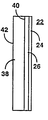
【0036】
そのスクリーン22は、基板24上に配設された3次元ホログラム26を備える。そのスクリーンは、プロジェクタからの画像を第1の入射表面側28で受け取り、表示されたすべての画像について制御された光拡散で画像を第2の出射表面側30上にその画像を表示する。その基板は、ポリエチレン・テレフタレート樹脂フィルムのような、耐久性が高く透明で、撥水性のあるフィルムが好ましい。このようなフィルムの1つは、商標Mylar(登録商標)として、E.I.du Pont de Nemours & Co.から得ることができる。そのフィルム基板は、約1ミル〜10ミル、すなわち、約0.001インチ〜0.01インチまたは約25.4ミクロン〜254ミクロンの範囲の厚さを有する。その厚さが約7ミル(177.8ミクロン)のフィルムは、その上に配設された3次元ホログラムを適切に支持することが判明している。そのフィルムの厚さは、一般にスクリーン性能に影響を与えず、また特に色ずれ性能に影響を与えず、いくつかの異なる厚さのフィルムを使用してもよい。その3次元ホログラム26の厚さは約20ミクロン以下である。
【0037】
この3次元ホログラフィック・スクリーンは少なくとも2つの供給源から得ることができる。Polaroid Corporationは独自の湿式化学プロセスを使用して、そのDMP−128光ポリマー材料で3次元ホログラムを形成している。
【0038】
本明細書で説明し請求するプロジェクション・テレビジョン受像機で使用されるその3次元ホログラフィック・スクリーンについて提起した実施形態は、以下の性能仕様にしたがってPolaroid Corporation湿式化学プロセスによって製造された。
水平半視野角:38度±3度
垂直半視野角:10度±1度
スクリーン利得:≧8
色ずれ:≦3
ここで、水平視野角および垂直視野角は従来の方法で測定され、スクリーン利得は、そのスクリーンに直交する方向で測定された、光源から視野表面の背面の方へ向かう光強度と視野表面の前面から観察者の方への光強度との商であり、色ずれは前述のように測定される。
【0039】
その3次元ホログラフィック・プロジェクション・スクリーンの並はずれた色ずれ性能は、概要で説明したように、全く予想外のものであった。
【0040】
図2は、色ずれ性能について説明するための、鏡およびレンズを省略したプロジェクション・テレビジョンの簡略図である。赤陰極線管14および青陰極線管18の光軸34および36は、緑陰極線管16の光軸32に対して入射角αの位置に対称的に位置合わせされる。キャビネットの最小奥行きDは、スクリーン22と陰極線管の背縁部との間の距離によって決定される。角度αを小さくすべきである場合、それぞれの陰極線管は互いに接近して配置しなければならず、かつ/あるいは陰極線管用のすきまを取るためにスクリーンからさらに離隔して設けなければならないことを理解されたい。これは、キャビネットの奥行き寸法Dの最小値を期待に反して増大させる。角度αが大きくなるにつれて、陰極線管をスクリーン22に近づけ、キャビネットの最小奥行きDを小さくすることができる。入射角の広い範囲で光を収集し、垂直軸により接近して並行に射出するホログラフィック・スクリーンは、実質的な光路長の短縮を可能にする。
【0041】
スクリーン22の視野側では、2つの水平半視野角は−βおよび+βとして指定される。総水平視野角2βも定義される。半視野角は通常、±40度から±60度の範囲である。各半角内に複数の特定の角度θがあり、この角度で、前述の数式(I)および(II)にしたがって色ずれを測定し求めることができる。
【0042】
入射角約10度または11度での既知の障壁に関して、3次元ホログラフィック・スクリーンの色ずれは、入射角が0度よりも大きくかつ約10度以下である第1のサブ・レンジ内のすべての入射角について約2以下であり、このスクリーンの色ずれは、入射角が約10度よりも大きくかつ約30度以下である第2のサブ・レンジ内のすべての入射角について約5以下である。第1のサブ・レンジのような約2以下の色ずれを、より大きな入射角の第2のサブ・レンジでも達成できることが期待される。
【0043】
図3を参照するとわかるように、基板24は、前述のように、Mylar(登録商標)などの透明フィルムを含む。3次元ホログラム26が形成される光ポリマー材料はフィルム層24上に支持される。適切な光ポリマー材料はDMP−128(登録商標)である。
【0044】
スクリーン22はさらに、たとえば、ポリメチルメタクリレート(PMMA)などのアクリル材料の光透過強化部材38を含むことができる。ポリカーボネート材料を使用することもできる。強化部材38はこの実施形態では、約2mm〜4mmの範囲の厚さを有する層である。スクリーン22および強化部材は、ホログラフィック層26と強化部材38の相互境界40全体にわたって互いに接着される。接着剤、放射、および/または熱結合技法を使用することができる。たとえば、ティンティング、惑光防止コーティング、耐ひっかきコーティングのうちの1つまたは複数によって強化層の表面42を処理することもできる。
【0045】
3次元ホログラフィック・プロジェクション・スクリーンの改良された色ずれ性能を低減せず、従来型のプロジェクション・スクリーンで知られているような、色ずれ性能以外の性能特性に関するプロジェクション・スクリーンの態様を制御するために、スクリーンおよび/またはその構成要素層の様々な表面に他の光学レンズまたはレンチキュラ・アレイを設けることができる。
【図面の簡単な説明】
【図1】 本明細書で教示される本発明の構成によるプロジェクション・テレビジョンの略図表現である。
【図2】 本発明の構成について説明するうえで有用なプロジェクション・テレビジョン幾何形状の簡略図である。
【図3】 本発明の構成による増強されたプロジェクション・スクリーンの側面図である。
【図4】 図1に示すものに似ているが、プロジェクタからレンズが外されている本発明の他の実施例によるプロジェクション・テレビジョンの略図表現である。[0001]
(background)
(Field of Invention)
The present invention relates generally to the field of projection television receivers, and more particularly to projection television receivers that result in significantly reduced color shift and / or reduced cabinet depth. Regarding the screen. According to an inventive aspect, holographic mirrors are used to correct certain optical effects caused by holographic screens.
[0002]
(Background information)
Color shift is determined by the projection images from the red, green, and blue projection tubes when viewed at various angles in the horizontal plane by observing the brightness peak at the vertical viewing angle. It is defined as the change in the red / blue or green / blue ratio of the white image formed in the center of the projection screen.
[0003]
The color misregistration problem arises as a result of the need for at least three image projectors for several different colors, for example red, blue and green images. The projection screen receives images from at least three projectors on the first side and displays the images on the second side with controlled light diffusion for all displayed images. One projector, i.e., usually green and usually in the center of the projector array, has a first light path in a direction generally perpendicular to the screen. At least two projectors, i.e. projectors, usually red and blue, usually positioned on either side of the central green projector in the array, have a first optical path in a direction other than orthogonal with a defined angle of incidence. Each optical path converges toward. Color misregistration is caused by the non-orthogonal relationship of the red and blue projectors to the screen and green projector. As a result of the color shift, the color tone will be different everywhere on the screen. A state where the color difference is large is often referred to as insufficient white uniformity. The smaller the color shift, the better the white uniformity.
[0004]
Color shifts are indicated by a numerical scale, with smaller numbers indicating weaker color shifts and better white uniformity. According to the general procedure, the red luminance, green luminance, from various horizontal viewing angles, usually in increments of 5 degrees or 10 degrees, at least from about -40 degrees to +40 degrees to about -60 degrees to +60 degrees, And the blue luminance value is measured on the screen. Positive and negative angles represent the right and left horizontal viewing angles with respect to the center of the screen, respectively. These measurements are taken at the peak vertical viewing angle. Red data, green data, and blue data are normalized to 1 at 0 degrees. One or both of the following equations (I) and (II) are evaluated at each angle.
[0005]
[Expression 1]
Where θ is an arbitrary angle within the horizontal viewing angle, C (θ) is the color shift at angle θ, red (θ) is the red luminance level at angle θ, and blue (θ) Is the blue luminance level at angle θ, and green (θ) is the green luminance level at angle θ. The maximum of these values is screen color misregistration.
[0007]
In general, the color shift should be nominally 5 or less in commercially acceptable screen designs. While other engineering and design constraints may sometimes require the color shift to be somewhat higher than 5, such color shift performance is undesirable and usually results in white uniformity. Results in poor perceptually inferior images.
[0008]
Screens for projection television receivers are typically manufactured by an extrusion process using one or more patterned rollers to form the surface of a thermoplastic sheet material. This shape is an array of lenticular elements, also commonly referred to as lenticules and lenslets. The lenticular elements can be formed on one or both sides of the same sheet material, or only on one side of several different sheets, and then these sheets can be combined permanently as a laminating unit or function as a laminating unit Can be attached in other ways to be adjacent to each other. In many designs, one surface of the screen is designed as a Fresnel lens to diffuse light. Prior art struggles to reduce color shift and improve white uniformity focus on only two aspects of the screen. One aspect is the shape and arrangement of the lenticular elements. The other aspect is a range of screen materials or screen materials that are partly doped with light diffusing particles to control light diffusion. These struggles are illustrated by the following patent documents:
[0009]
In US Pat. No. 4,432,010 and US Pat. No. 4,536,056, the projection screen includes a light transmissive lenticular sheet having an entrance surface and an exit surface. The input surface is characterized by a horizontal diffusion lenticular profile having a ratio (Xv / R1) of undulation depth Xv and paraxial radius of curvature R1 in the range of 0.5 to 1.8. The profile is vertically long along the optical axis, forming an aspheric input lenticular lens.
[0010]
It is common to use a screen with a double-sided lenticular lens. Such a screen comprises a cylindrical entrance lenticular element on the entrance surface of the screen, a cylindrical lenticular element formed on the exit surface of the screen, and a light absorbing layer formed on the light non-convergent portion of the exit surface. Have. The incident lenticular element and the outgoing lenticular element are each shown in the shape of a circle, an ellipse, or a hyperbola represented by the following formula (III).
[0011]
[Expression 2]
Where C is the principal curvature and K is the conic constant.
[0013]
Alternatively, the lenslet group has a curve with a higher order term added than the second order.
[0014]
For screens made using something like a double-sided lenticular lens, it has been proposed to identify the positional relationship between the entrance and exit lenses, or between the lenticular elements that form the lens. Yes. For example, US Pat. No. 4,443,814 teaches positioning the entrance and exit lenses so that the lens surface of one lens is at the focal point of the other lens. For example, Japanese Patent Application No. 58-59436 teaches that the eccentricity of the incident lens is approximately equal to the reciprocal of the refractive index of the material comprising the lenticular lens. Further, for example, in US Pat. No. 4,502,755, two sheets of double-sided lenticular lenses are combined so that the optical axis planes of the respective lenticular lenses are perpendicular to each other, and the periphery of one lens Forming a double-sided lenticular lens in which the entrance and exit lenses are asymmetric with respect to the optical axis. In U.S. Pat. No. 4,953,948, light is transmitted only at the valley of the incident lens so that the tolerance of the optical axis misalignment and the tolerance of the thickness difference can be increased or the color misregistration can be reduced. It is also taught to shift the convergence position from the exit lens surface toward the field of view.
[0015]
In addition to various proposals to reduce color drift or white non-uniformity, other proposals to improve projection screen performance include brightening images both horizontally and vertically. , Is directed to ensuring an appropriate vision. Such technology is not a direct concern and is not described in detail. A summary of many such proposals is described in US Pat. No. 5,196,960. This patent itself includes an entrance lens layer having an entrance lens and an exit lens layer having an exit lens, and the lens surface of the exit lens is formed at or near the light convergence point of the entrance lens, and the entrance lens layer and the exit lens. Each of the layers is formed of a substantially transparent thermoplastic resin, and at least the exit layer includes diffusing fine particles, and a double-sided lenticular lens sheet having a difference in light diffusion characteristics between the entrance lens layer and the exit lens layer. Teaching. A plurality of incident lenses form a cylindrical lens. The exit lens is formed of a plurality of exit lens layers, and has a lens surface at or near the light convergence point of each lens of the entrance lens layer. Further, the light absorption layer is formed in the non-converging portion of the outgoing lens layer. This screen design is said to provide a sufficient horizontal viewing angle, reduce color shift, brighten the image and facilitate manufacturing by an extrusion process.
[0016]
Despite being actively developed over many years in projection screen design, the improvements achieved are incremental at best and have not succeeded in exceeding certain standards. . Its angle of incidence, defined by the geometry of the image projector, is referred to herein as angle α and is generally limited to a range that is greater than 0 degrees and less than or equal to about 10 degrees or 11 degrees. Due to the dimensions of the optical system of the image projector, it is almost impossible to make the angle α close to 0 degrees. In the range where angle α is less than about 10 degrees or 11 degrees, the best color shift performance achieved is about 5, as measured according to equations (I) and (II). The best color shift performance already achieved with angles exceeding about 10 degrees or 11 degrees is not commercially accepted. Actually, there is no known projection television receiver having an angle α larger than 10 degrees or 11 degrees.
[0017]
If the angle of α is small, it will cause noticeable and undesirable results, i.e. a very large cabinet depth is required for a home projection television receiver. This large depth is a direct result of the need to deal with optical paths with small incident angles (α). Techniques for reducing the dimensions of a projection television cabinet generally rely on an arrangement of mirrors. Such efforts are ultimately limited by the narrow range of incident angles.
[0018]
Polaroid Corporation sells a photopolymer designed as DMP-128® and can be manufactured as a three-dimensional hologram using a process exclusive to Polaroid Corporation. The holographic manufacturing process is described in part in US Pat. No. 5,576,853. A three-dimensional holographic screen for projection television is one of many proposals presented in the process of making efforts to establish a market for DMP-128® photopolymer holographic products. Proposed by Polaroid Corporation. This proposal was based on the benefits expected by Polaroid Corporation regarding the items of higher brightness and resolution, lower manufacturing costs, lower weight, and resistance to wear that the two-piece screen experiences during transport. It was. Polaroid Corporation does not propose any specific holographic configuration for a large amount of holographic elements that can create things like holographic projection television screens, holographic or other types Regardless of the color misregistration problem in any kind of projection television screens is not even considered.
[0019]
In general, a projection screen having a screen with a color shift less than 5 and possibly much less than 5 and a screen with a color shift as low as 5 when the angle α is much greater than 10 or 11 degrees. Incremental changes in lenticular element shape and position and diffuser in conventional projection screens, despite the intensive development over the years to provide a television receiver Other than that, the solution to the color misregistration problem has not progressed. In addition, a projection television using a three-dimensional holographic screen is provided because there is no color misregistration despite the proposal that a three-dimensional hologram is useful for the projection screen. No effort has been made. The long-awaited need for a projection television receiver that has significantly improved color shift performance and can be incorporated into a significantly smaller cabinet remains unfulfilled.
[0020]
(wrap up)
Projection television receivers according to the configurations of the invention taught herein significantly improve color shift performance measured as a quantity, ie, having an incident angle α in the range of less than 10 degrees or 11 degrees. A color shift of 2 or less can be achieved using a projection television receiver. Furthermore, due to the significantly high color shift performance, a commercially acceptable projection television receiver with an incident angle up to about 30 degrees can be provided in a much smaller cabinet. The color misregistration performance of such a large α angle receiver is at least as good as, for example, a small α angle conventional receiver with a color misregistration performance of 5, similar to a receiver with a small α angle. In addition, it can be expected to approach values as low as about 2, or in some cases to reach such values.
[0021]
These results are obtained by completely abandoning the extruded lens screen technique. Instead, the projection television receiver according to the configuration of the present invention has a screen formed of a three-dimensional hologram formed on a substrate (base layer), for example, a polyethylene film such as Mylar®.
[0022]
Such a three-dimensional holographic screen initially has the expected benefits in terms of higher brightness and resolution, lower manufacturing costs, lower weight, and resistance to wear that the two-piece screen experiences, for example during transport Developed for. The color shift performance of the 3D holographic screen was found when tested to determine if the optical properties of the 3D screen were at least as good as conventional screens. It was. The color misregistration performance of the three-dimensional holographic screen measured by Equations (I) and (II) was shockingly lower than expected. The barrier that limited the improvement of the prior art to incremental steps was completely eliminated. It is now possible to develop even smaller cabinets with a projection geometry that is characterized by a larger alpha incident angle.
[0023]
A projection television according to the configuration of the present invention that has more than expected properties associated with a three-dimensional holographic screen and that is taught herein consists of: At least three image projectors for each image of each different color; formed with a three-dimensional hologram disposed on the substrate, receives the image from the projector on the first surface and controls for all displayed images A projection screen for displaying an image on a second surface with a diffused light diffusion; one of the projectors has a first light path in a direction substantially perpendicular to the screen, and at least two of the projectors are defined Each light path converges towards the first light path in a direction that is not orthogonal to the screen at an incident angle; and the three-dimensional hologram representing the three-dimensional diffractive array is the displayed image Effective in reducing color misregistration, and the screen is within a range of greater than 0 degrees and less than about 30 degrees. The angle of incidence of all having a color shift is about 5 or less, wherein the color shift is determined by the maximum value obtained from at least one of the following formulas:
[0024]
[Equation 3]
Here, θ is an arbitrary angle within a series of horizontal viewing angles, C (θ) is a color shift at angle θ, red (θ) is a red luminance level at angle θ, and blue (θ) is The blue luminance level at the angle θ, and green (θ) is the green luminance level at the angle θ. The screen color shift can be expected to be less than 5, for example, about 4, 3, or in some cases 2 or less.
[0026]
For known barriers when the angle of incidence is about 10 or 11 degrees, the color shift of the screen is all incidents in the first sub-range of angles of incidence that are greater than 0 degrees and less than or equal to about 10 degrees. About 2 or less for angles, and about 5 or less for all incident angles in the second sub-range of incident angles that are greater than about 10 degrees and less than or equal to about 30 degrees.
[0027]
The screen further comprises a layered acrylic material light transmission enhancing member having a thickness in the range of about 2 mm to 4 mm, for example. The substrate is made of a highly durable and transparent water-repellent film such as a polyethylene terephthalate resin film. The substrate may be a film having a thickness in the range of about 1 mil to 10 mil (about 25.4 microns to 254 microns). A thickness of about 7 mils (177.8 microns) has been found to adequately support the three-dimensional hologram. The thickness of the film has nothing to do with performance. The three-dimensional hologram has a thickness in the range of about 20 microns or less.
[0028]
In accordance with an inventive aspect, a projection television further comprises one or more holographic optical elements in addition to the holographic projection screen. In one embodiment, the provided projection television has at least three image projectors that project respective images of different colors on the projection screen, and one projector is in a direction substantially perpendicular to the screen. And the image projector and the screen have at least two projectors, each having a non-vertical optical path that defines an angle of incidence and a respective optical path that converges toward the first optical path. And an optical system including a holographic mirror (reflecting mirror) disposed in optical cooperation with the optical system. The projection screen is formed from a three-dimensional hologram showing a three-dimensional diffraction array on a substrate. The screen receives the image from the projector on the first side and displays the image on the second side showing controlled light diffusion for all of the displayed images.
[0029]
From another point of view, the described projection television gin is given a panchromatic (hollow-color) holographic mirror (reflector) in optical cooperation with its image projector and its screen. Panchromatic holographic mirrors are pre-selected to match the wavelength that affects the light reflection characteristics to compensate for chromatic aberrations induced in the image by the projection screen, and the light wavelength Condition an image as a function of. The projection screen is formed from a three-dimensional hologram that represents a three-dimensional diffraction array on the substrate. The screen receives the image from the projector on the first side and displays the image on the second side showing controlled light diffusion for all of the displayed images.
[0030]
(Description of preferred embodiment)
A
[0031]
According to an inventive aspect, the optical correction applied to the image between the projection tube and the screen is assigned to the cooperation of the
[0032]
According to another aspect of the invention, the
[0033]
When using a mirror formed by a panchromatic holographic mirror, the
[0034]
In another aspect of the invention, the
[0035]
In another aspect of the invention, the optical system can be adapted to correct chromatic aberrations, and in particular to cancel out more chromatic aberrations that occur along the optical path by the
[0036]
The
[0037]
This three-dimensional holographic screen can be obtained from at least two sources. Polaroid Corporation uses a unique wet chemical process to form a three-dimensional hologram with its DMP-128 photopolymer material.
[0038]
The proposed embodiments for the three-dimensional holographic screen used in the projection television receiver described and claimed herein were manufactured by the Polaroid Corporation wet chemical process according to the following performance specifications.
Horizontal half viewing angle: 38 degrees ± 3 degrees Vertical half viewing angle: 10 degrees ± 1 degree Screen gain: ≧ 8
Color shift: ≦ 3
Here, the horizontal and vertical viewing angles are measured in a conventional manner, and the screen gain is measured in the direction orthogonal to the screen, the light intensity from the light source towards the back of the viewing surface and the front of the viewing surface. Is the quotient of the light intensity from the viewer to the viewer, and the color shift is measured as described above.
[0039]
The extraordinary color shift performance of the three-dimensional holographic projection screen was completely unexpected, as explained in the overview.
[0040]
FIG. 2 is a simplified diagram of a projection television in which a mirror and a lens are omitted for explaining the color misregistration performance. The
[0041]
On the viewing side of the
[0042]
For known barriers at an incident angle of about 10 or 11 degrees, the color shift of the 3D holographic screen is all within the first sub-range where the incident angle is greater than 0 degrees and less than or equal to about 10 degrees. The screen color shift is less than about 5 for all angles of incidence in the second sub-range where the angle of incidence is greater than about 10 degrees and less than about 30 degrees. is there. It is expected that a color shift of about 2 or less as in the first sub-range can be achieved even in the second sub-range with a larger incident angle.
[0043]
As can be seen with reference to FIG. 3, the
[0044]
The
[0045]
Control the aspect of the projection screen with respect to performance characteristics other than the color misregistration performance, as is known in conventional projection screens, without reducing the improved color misregistration performance of the 3D holographic projection screen. To that end, other optical lenses or lenticular arrays can be provided on various surfaces of the screen and / or its component layers.
[Brief description of the drawings]
FIG. 1 is a schematic representation of a projection television according to the arrangement of the invention taught herein.
FIG. 2 is a simplified diagram of a projection television geometry useful in describing the configuration of the present invention.
FIG. 3 is a side view of an enhanced projection screen according to an arrangement of the present invention.
FIG. 4 is a schematic representation of a projection television similar to that shown in FIG. 1, but according to another embodiment of the present invention with the lens removed from the projector.
Claims (20)
基板上に3次元回折アレイを示す3次元ホログラムを含み、第1の側面に前記プロジェクタからの画像を受け、ディスプレイされた画像のすべてについて制御された光拡散を示して第2の側面上に前記画像をディスプレイする前記プロジェクション・スクリーンと
を備えることを特徴とするプロジェクション・テレビジョン。At least three image projectors for projecting respective images of the individual colors on the projection screen, one of the projector has a first optical path in a direction substantially perpendicular to the screen, before Symbol projector At least two of the optical paths are non-vertical directions that define an incident angle, and have optical links with the image projector and the screen so that each optical path converges toward the first optical path. An optical system including a holographic mirror disposed;
Including a three-dimensional hologram representing a three-dimensional diffractive array on a substrate, receiving an image from the projector on a first side, and showing controlled light diffusion for all of the displayed images on the second side A projection television comprising: the projection screen for displaying an image.
前記スクリーンの色ずれは、入射角が約10度よりも大きくかつ約30度以下である第2のサブ・レンジ内のすべての前記入射角について約5以下であることを特徴とする請求項1に記載のプロジェクション・テレビジョン。The screen has a color shift of less than or equal to about 2 for all the angles of incidence within a first sub-range having an incident angle greater than 0 degrees and less than or equal to about 10 degrees;
2. The color shift of the screen is about 5 or less for all the incident angles in the second sub-range where the incident angle is greater than about 10 degrees and less than or equal to about 30 degrees. Projection television set forth in 1.
水平半視野角:38度±3度
垂直半視野角:10度±1度
スクリーン利得:≧8
色ずれ:≦3
の各性能仕様を有することを特徴とする請求項1に記載のプロジェクション・テレビジョン。The three-dimensional hologram (26)
Horizontal half viewing angle: 38 degrees ± 3 degrees Vertical half viewing angle: 10 degrees ± 1 degree Screen gain: ≧ 8
Color shift: ≦ 3
The projection television according to claim 1, having the following performance specifications.
プロジェクション・スクリーン上に個別の色のそれぞれの画像を投影する少なくとも3つの画像プロジェクタと、前記プロジェクタの1つは前記スクリーンに対して実質的に垂直の方向に第1の光路を持ち、前記プロジェクタの少なくとも2つは入射角を規定する非垂直方向の光路で、第1の光路に向かって収束するそれぞれの光路を持つように、その前記画像プロジェクタと前記スクリーンに対して光学的連携を持って配置されているホログラフィック・ミラーであって、前記プロジェクション・スクリーンによって前記画像に引き起こされる色収差を補償するように、前記画像をあらかじめ調整するためにあらかじめ選択された波長依存光反射特性を持つホログラフィック・ミラーとを備える光学システムと、
基板上に配置されたレンチキュラ・エレメントの3次元アレイを示す3次元ホログラムにより形成され、第1の側面に前記プロジェクタからの画像を受け、前記ディスプレイされた画像のすべてについて制御された光拡散を示して第2の側面上に前記画像をディスプレイする前記プロジェクション・スクリーンと
を備えることを特徴とするプロジェクション・テレビジョン。In projection television
At least three image projectors for projecting respective images of the individual colors on the projection screen, one of the projector has a first optical path in a direction substantially perpendicular to the screen, before Symbol projector At least two of the optical paths are non-vertical directions that define an incident angle, and have optical links with the image projector and the screen so that each optical path converges toward the first optical path. a holographic mirror disposed, so as to compensate for chromatic aberration caused in the image by the previous SL projection screen, having a preselected wavelength dependent light reflection properties in order to precondition the image An optical system comprising a holographic mirror ;
Formed by the three-dimensional hologram of a three dimensional array of lenticular elements disposed on a base plate, it receives the image from the projector to the first aspect, the light diffusion controlled for all of the display image The projection screen for displaying the image on a second side;
Projection television which is characterized in that it comprises.
前記スクリーンの色ずれは、入射角が約10度よりも大きくかつ約30度以下である第2のサブ・レンジ内のすべての前記入射角について約5以下であることを特徴とする請求項11に記載のプロジェクション・テレビジョン。The screen has a color shift of less than or equal to about 2 for all the angles of incidence within a first sub-range having an incident angle greater than 0 degrees and less than or equal to about 10 degrees;
12. The color misregistration of the screen is about 5 or less for all the incident angles in the second sub-range whose incident angle is greater than about 10 degrees and less than or equal to about 30 degrees. Projection television set forth in 1.
水平半視野角:38度±3度
垂直半視野角:10度±1度
スクリーン利得:≧8
色ずれ:≦3
の各性能仕様を有することを特徴とする請求項11に記載のプロジェクション・テレビジョン。The three-dimensional hologram is
Horizontal half viewing angle: 38 degrees ± 3 degrees Vertical half viewing angle: 10 degrees ± 1 degree Screen gain: ≧ 8
Color shift: ≦ 3
The projection television according to claim 11, having the following performance specifications.
Applications Claiming Priority (5)
| Application Number | Priority Date | Filing Date | Title |
|---|---|---|---|
| US5262197P | 1997-07-15 | 1997-07-15 | |
| US5331797P | 1997-07-21 | 1997-07-21 | |
| US60/052,621 | 1997-07-21 | ||
| US60/053,317 | 1997-07-21 | ||
| PCT/US1998/001617 WO1999004576A1 (en) | 1997-07-15 | 1998-01-29 | Holographic screen projection televisions with optical correction |
Publications (3)
| Publication Number | Publication Date |
|---|---|
| JP2001510967A JP2001510967A (en) | 2001-08-07 |
| JP2001510967A5 JP2001510967A5 (en) | 2005-12-22 |
| JP3990536B2 true JP3990536B2 (en) | 2007-10-17 |
Family
ID=26730871
Family Applications (1)
| Application Number | Title | Priority Date | Filing Date |
|---|---|---|---|
| JP2000503665A Expired - Fee Related JP3990536B2 (en) | 1997-07-15 | 1998-01-29 | Holographic screen projection television with optical correction |
Country Status (7)
| Country | Link |
|---|---|
| EP (1) | EP0995319B1 (en) |
| JP (1) | JP3990536B2 (en) |
| KR (1) | KR100525622B1 (en) |
| CN (1) | CN100372384C (en) |
| AU (1) | AU6136398A (en) |
| DE (1) | DE69815107T2 (en) |
| WO (1) | WO1999004576A1 (en) |
Families Citing this family (7)
| Publication number | Priority date | Publication date | Assignee | Title |
|---|---|---|---|---|
| CN100460928C (en) * | 2005-01-07 | 2009-02-11 | 康佳集团股份有限公司 | Optical path system of projection TV |
| JP5502484B2 (en) * | 2006-10-19 | 2014-05-28 | クリエーター テクノロジー ビー ヴィ | Front lighting of rollable or wrappable display devices |
| CN103399409B (en) * | 2013-08-01 | 2015-10-28 | 清华大学深圳研究生院 | A kind of stereo projection display apparatus |
| FR3011644B1 (en) | 2013-10-03 | 2016-01-01 | Commissariat Energie Atomique | RETROPROJECTION DISPLAY DEVICE |
| CN103888757A (en) * | 2014-03-24 | 2014-06-25 | 中国人民解放军国防科学技术大学 | Numerous-viewpoint naked-eye three-dimensional digital stereographic projection display system |
| US10321105B2 (en) | 2014-07-31 | 2019-06-11 | Vuzix Corporation | Image and wave field projection through diffusive media |
| CN113589548A (en) * | 2021-07-28 | 2021-11-02 | 深圳臻像科技有限公司 | Planar transmission type 3D light field display system based on projection array |
Family Cites Families (14)
| Publication number | Priority date | Publication date | Assignee | Title |
|---|---|---|---|---|
| US5016950A (en) * | 1988-07-05 | 1991-05-21 | Hughes Aircraft Company | Full-color zero-order suppressed diffraction optics diffusing screen/louver filter laminate |
| US4960314A (en) * | 1988-07-05 | 1990-10-02 | Hughes Aircraft Company | Diffraction optics diffusing screen laminate for full color on-axis viewing |
| US5046793A (en) * | 1989-05-26 | 1991-09-10 | Litton Systems, Inc. | Chromatically corrected directional diffusing screen |
| EP0479490A3 (en) * | 1990-10-02 | 1992-08-12 | Physical Optics Corporation | Volume holographic diffuser |
| US5349400A (en) * | 1990-11-30 | 1994-09-20 | Thomson-Csf | Back-projection display system and method for making a back-projection mirror |
| JP3340766B2 (en) * | 1992-09-03 | 2002-11-05 | 株式会社リコー | Transmission projection screen |
| WO1995034832A1 (en) * | 1992-12-15 | 1995-12-21 | Thomson-Csf | Holographic projection screen and method for its production |
| DE69526641T2 (en) * | 1994-09-06 | 2003-01-30 | Koninkl Philips Electronics Nv | REAR SCREEN |
| JPH08292498A (en) * | 1995-04-19 | 1996-11-05 | Asahi Glass Co Ltd | Image display device |
| JPH0973133A (en) * | 1995-09-05 | 1997-03-18 | Casio Comput Co Ltd | Transmission type screen |
| JPH0973132A (en) * | 1995-09-05 | 1997-03-18 | Casio Comput Co Ltd | Transmission type screen and display device using the same |
| AU3481495A (en) * | 1995-09-15 | 1997-04-01 | Richmond Holographic Research & Development Limited | Projection system |
| JPH09113995A (en) * | 1995-10-23 | 1997-05-02 | Denso Corp | Display device |
| JP3525584B2 (en) * | 1995-10-24 | 2004-05-10 | 株式会社デンソー | Hologram display device |
-
1998
- 1998-01-29 EP EP98906024A patent/EP0995319B1/en not_active Expired - Lifetime
- 1998-01-29 KR KR10-2000-7000374A patent/KR100525622B1/en not_active IP Right Cessation
- 1998-01-29 AU AU61363/98A patent/AU6136398A/en not_active Abandoned
- 1998-01-29 DE DE69815107T patent/DE69815107T2/en not_active Expired - Fee Related
- 1998-01-29 JP JP2000503665A patent/JP3990536B2/en not_active Expired - Fee Related
- 1998-01-29 CN CNB988071169A patent/CN100372384C/en not_active Expired - Fee Related
- 1998-01-29 WO PCT/US1998/001617 patent/WO1999004576A1/en active IP Right Grant
Also Published As
| Publication number | Publication date |
|---|---|
| DE69815107D1 (en) | 2003-07-03 |
| KR100525622B1 (en) | 2005-11-03 |
| WO1999004576A1 (en) | 1999-01-28 |
| EP0995319B1 (en) | 2003-05-28 |
| DE69815107T2 (en) | 2004-01-29 |
| KR20010021810A (en) | 2001-03-15 |
| AU6136398A (en) | 1999-02-10 |
| CN100372384C (en) | 2008-02-27 |
| CN1263671A (en) | 2000-08-16 |
| JP2001510967A (en) | 2001-08-07 |
| EP0995319A1 (en) | 2000-04-26 |
Similar Documents
| Publication | Publication Date | Title |
|---|---|---|
| US6639631B1 (en) | Projection television using a holographic screen | |
| KR100517427B1 (en) | Projection televisions with holographic screens having center to edge variations | |
| JP3990536B2 (en) | Holographic screen projection television with optical correction | |
| US6483533B1 (en) | Projection televisions with three dimensional holographic screens | |
| JP3901740B2 (en) | Projection television using holographic screens | |
| JP3900332B2 (en) | Projection television using holographic screens | |
| JP3897980B2 (en) | Projection television having a mirror incident on a holographic screen | |
| EP1051858B1 (en) | Projection television with holographic screen and partly occluded projection lens | |
| US6621530B1 (en) | Projection televisions with mirrors incident on holographic screens | |
| JP3897979B2 (en) | Projection television with a three-dimensional holographic screen and a central blue CRT for balanced CRT drive | |
| EP0956708B1 (en) | Projection television using a holographic screen | |
| US6400417B1 (en) | Projection television with three-dimensional holographic screen and centered blue CRT for balanced CRT drive | |
| EP1051855A1 (en) | Projection televisions with holographic screens for high off axis exclusion | |
| MXPA99006181A (en) | Projection televisions with three-dimensional holographic screens | |
| MXPA99006975A (en) | Projection television using a holographic screen | |
| MXPA99006978A (en) | Projection televisions with holographic screens having center to edge variations |
Legal Events
| Date | Code | Title | Description |
|---|---|---|---|
| A521 | Written amendment |
Free format text: JAPANESE INTERMEDIATE CODE: A523 Effective date: 20050118 |
|
| A621 | Written request for application examination |
Free format text: JAPANESE INTERMEDIATE CODE: A621 Effective date: 20050118 |
|
| RD04 | Notification of resignation of power of attorney |
Free format text: JAPANESE INTERMEDIATE CODE: A7424 Effective date: 20050118 |
|
| A131 | Notification of reasons for refusal |
Free format text: JAPANESE INTERMEDIATE CODE: A131 Effective date: 20061215 |
|
| A601 | Written request for extension of time |
Free format text: JAPANESE INTERMEDIATE CODE: A601 Effective date: 20070315 |
|
| A602 | Written permission of extension of time |
Free format text: JAPANESE INTERMEDIATE CODE: A602 Effective date: 20070402 |
|
| A521 | Written amendment |
Free format text: JAPANESE INTERMEDIATE CODE: A523 Effective date: 20070615 |
|
| TRDD | Decision of grant or rejection written | ||
| A01 | Written decision to grant a patent or to grant a registration (utility model) |
Free format text: JAPANESE INTERMEDIATE CODE: A01 Effective date: 20070710 |
|
| A61 | First payment of annual fees (during grant procedure) |
Free format text: JAPANESE INTERMEDIATE CODE: A61 Effective date: 20070720 |
|
| FPAY | Renewal fee payment (event date is renewal date of database) |
Free format text: PAYMENT UNTIL: 20100727 Year of fee payment: 3 |
|
| R150 | Certificate of patent or registration of utility model |
Free format text: JAPANESE INTERMEDIATE CODE: R150 |
|
| LAPS | Cancellation because of no payment of annual fees |