JP3989757B2 - Signal recording device for disc - Google Patents
Signal recording device for disc Download PDFInfo
- Publication number
- JP3989757B2 JP3989757B2 JP2002077306A JP2002077306A JP3989757B2 JP 3989757 B2 JP3989757 B2 JP 3989757B2 JP 2002077306 A JP2002077306 A JP 2002077306A JP 2002077306 A JP2002077306 A JP 2002077306A JP 3989757 B2 JP3989757 B2 JP 3989757B2
- Authority
- JP
- Japan
- Prior art keywords
- recording
- disk
- disc
- unrecorded
- recorded
- Prior art date
- Legal status (The legal status is an assumption and is not a legal conclusion. Google has not performed a legal analysis and makes no representation as to the accuracy of the status listed.)
- Expired - Fee Related
Links
- 238000000034 method Methods 0.000 description 19
- 230000003287 optical effect Effects 0.000 description 8
- 238000004519 manufacturing process Methods 0.000 description 5
- 230000007246 mechanism Effects 0.000 description 3
- 230000002159 abnormal effect Effects 0.000 description 2
- 238000005452 bending Methods 0.000 description 2
- 230000000694 effects Effects 0.000 description 2
- 230000005856 abnormality Effects 0.000 description 1
- 230000008602 contraction Effects 0.000 description 1
- 230000007423 decrease Effects 0.000 description 1
- 230000006866 deterioration Effects 0.000 description 1
- 238000007599 discharging Methods 0.000 description 1
- 238000000926 separation method Methods 0.000 description 1
- 229920003002 synthetic resin Polymers 0.000 description 1
- 239000000057 synthetic resin Substances 0.000 description 1
Images


Landscapes
- Manufacturing Optical Record Carriers (AREA)
Description
【0001】
【発明の属する技術分野】
本発明は、光ディスクなどに制御信号などを記録するためのディスクへの信号記録装置の技術分野に属する。
【0002】
【従来の技術】
情報の記録媒体としてはテープやディスクなどいろいろな媒体が提供されている。それらは、形態や記録原理に応じて、多数の種類に分類することができ、それぞれが特徴を持っている。それらの多数の種類の記録媒体の中にあって、最近では交換可能な大容量記録媒体として光学的な記録方式を使用した光ディスク装置が利用されている。光ディスクは、記録原理によっていくつかに分類でき、それぞれが工業標準規格に準じて実用化されている。光ディスクは、総じて大量生産に向いているため価格が安く、記録の信頼性も高い。さらに、テープに比べれば情報の複製が容易なため将来にわたって利用分野を拡大していくことが予想されている。
【0003】
ところで、光ディスクの種類の中には、ディスクの製造工程の中で、ディスクに識別情報や制御に使用する制御信号を記録する必要のあるものがある。この制御信号は、ディスクを回転させながら、ディスクに一枚ずつ記録する。制御信号を記録する工程は、光ディスクを生産する工程の中の一工程として組み込まれており、制御信号記録工程と呼ばれている。制御信号の記録工程は、制御信号を記録するために特別に設計されたディスクへの信号記録装置を使用する。1枚のディスクに制御信号を記録するためには、3秒から120秒程度の時間が必要である。この時間は、ディスクの製造工程で他の工程よりも長い時間を必要とする。光ディスクを大量に生産する場合は、全ての工程を通じてボトルネックが生じないようにする必要があるが、そのためには、この制御信号を記録する工程も他の工程の速度と合わせる必要がある。
【0004】
ひとつの解決方法は、時間がかかる工程は、その工程を受け持つ装置を複数並列に並べ同時に並行運転することで他の工程との速度差を解消する。従来のディスクへの信号記録装置はいろいろなものが知られているが、特開平10−269679(G11B19/02)や、USP5291456などに示されたメカニズムが使用可能である。これらの文献に示された技術は、制御信号を記録するためのものではなくディスク全面に信号を記録するためのものである。ここに示された装置は、ディスクに信号を記録する記録部分と、記録部分に未記録のディスクを自動的に供給する供給部分と、記録の終わったディスクを記録部分から自動的に取り出す排出部分を備えており、ディスクの製造工程に組み込んで自動的に制御信号を記録するディスクへの信号記録装置に必要な要素を全て備えている。
【0005】
これらの文献に示された装置は、ディスク1枚への信号の記録に要する時間が、240秒から600秒以上かかる場合は合理的である。すなわち、ディスクを自動的に取得し、ディスクに信号を記録し、記録が終わったディスクを自動的に排出することができるため、ディスクの生産工程に組み込むことが容易にできる。もし、この工程で必要な時間を短縮する必要があれば、装置の台数を増やして並列に同時運転をすればよい。しかし、ディスク1枚への信号の記録に要する時間が短い場合は、ここに例示した装置では能率が良くない。確かに、装置の台数を増加させれば、この工程での時間は短縮できるのであるが、ディスクに実際に信号を記録している時間の割には、能率があがらないのである。
【0006】
発明者は、その原因をさまざまな観点から調査検討した。その結果、ディスクに信号を記録するときに、記録に要する時間が短い場合は、ディスクの自動取得に要する時間と、ディスクを排出するのに要する時間の比率が予想以上に大きく、無視できなくなるとの結論に達した。しかも、単に供給部分の動作速度を上げる程度の改良では、大幅な能率向上は見込めないとの結論に達した。この主な原因をさらに検討してみると、ディスクに信号を記録する記録部分での時間が短くなればなるほど、記録済みのディスク排出と未記録のディスクの供給に要する時間の比率が上昇し、記録部分の待ち時間の比率が上がることがわかった。具体的にには、供給に15秒かかり、記録に270秒かかり、排出に15秒かかる場合は、信号記録行程300秒のうち、供給と排出にかかる時間の比率は10%である。しかし、記録に30秒かかる場合は、信号記録行程60秒のうち、供給と排出にかかる時間の比率は50%になる。さらに、記録時間が10秒になると、信号記録工程の実に75%がディスクの供給と排出で占められることになる。こうなると、記録工程がボトルネックにならないようにするには、非常に多くの記録装置を並行運転する必要があり、多数の並行運転する装置全体の自動的な運用を維持するには、大規模な制御機構を併設することが避けられない。
【0007】
【発明が解決しようとする課題】
従来のディスクへの信号記録装置は、ディスク1枚に対する信号の記録に要する時間が長い場合には特に問題はないが、記録に要する時間が短くなってくると短くなるほど能率が悪くなるという問題があった。本発明は、ディスク1枚に対する信号の記録に要する時間が短い場合に、能率が低下しないディスクへの信号記録装置を得ることを目的とする。
【0008】
【課題を解決するための手段】
本発明は、この課題を解決するために、請求項1記載の発明は、未記録のディスクに信号を記録し、記録済みのディスクを生産するためのディスクへの信号記録装置において、前記未記録のディスクを所定の位置に保持する未記録ディスク保持手段と、前記未記録のディスクを保持し、前記未記録のディスクに信号を記録し、前記記録済みディスクとする記録手段と、前記記録済みディスクを所定の位置に保持する記録済みディスク保持手段と、前記未記録ディスクを前記未記録ディスク保持手段から受け取って前記記録手段に取りつける第1の移送手段と、前記記録済みディスクを前記記録手段から取り外して前記記録済みディスク保持手段に引き渡す第2の移送手段とから構成され、前記第1の移送手段と前記第2の移送手段とが別個の手段であり、別個に駆動され、前記第2の移送手段が前記記録手段から前記記録済みディスクを取り外す前に、前記第1の移送手段が前記未記録ディスク保持手段から受け取った未記録ディスクを保持して待機していることを特徴とするディスクへの信号記録装置としたものである。
【0009】
また、請求項2記載の発明は、請求項1記載のものにおいて、前記記録手段は、未記録のディスクに信号を記録するための記録ユニットを複数含んでいることを特徴とするディスクへの信号記録装置としたものである。
【0010】
【実施の態様】
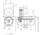
図1は、本発明の実施の態様を示した正面図であり、図2は一部を断面として示したその平面図である。1は、ディスクへの信号記録装置の全体である。信号記録装置1は、全体として右側部分、中央部分及び左側部分の3つの部分からなっている。図1及び図2において、未記録のディスクは、図面の右側の部分から供給され、中央の部分で信号が記録され、最後に左側部分に向けて排出される。2は、信号記録装置1の右側部分に配置された未記録ディスク保持手段である。未記録ディスク保持手段2は、未記録のディスクを積み重ねて保持する。3は、信号記録装置1の中央部分に配置された記録手段である。記録手段3は、未記録のディスクに信号を記録して記録済みのディスクとする。4は、信号記録装置1の左側部分に配置された記録済みディスク保持手段である。記録済みディスク保持手段4は、記録済みディスクを積み重ねて保持する。5は、第1の移送手段である。第1の移送手段は、未記録ディスク保持手段2から未記録のディスクを1枚取り出し、記録手段3まで移送する。6は、第2の移送手段である。第2の移送手段6は、記録手段3から記録済みのディスクを取り出して、記録済みディスク保持手段4まで移送する。7は、廃棄手段である。廃棄手段7は、未記録のディスクで規格に適合しないものがあった場合や、記録手段3によって信号を記録した場合に、規格に適合しないディスクを廃棄するためのものである。
【0011】
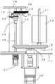
図3は、未記録ディスク保持手段2の構成を示した部分拡大図である。未記録ディスク保持手段2は、ターンテーブル9と、シャフト10、11と、エレベータ12から構成されている。ターンテーブル9は、シャフト10、11などに積み重ねた未記録のディスクを切り替える。シャフト10、11などは、未記録のディスクを積み重ねて供給する場合の案内シャフトである。エレベータ12は、シャフト10に積み重ねられた未記録のディスクの最上部を第1の移送手段5に対して位置決めする。未記録のディスク13は、直径が12センチメートル程度の合成樹脂性の薄い円盤であり中心に円形の穴があいている。
【0012】
シャフト10は、そのディスク13の中心の穴に挿入されている。ディスク13は、シャフト10を軸として積み重ねられている。ターンテーブル9は、4つのシャフト受け15を備えており、回転軸14を中心に90度ずつ回転可能である。図3では、シャフトは10、11の2本のみを示すが、ターンテーブル9は、実際には4本のシャフトを支持することができる。図3において16はモータである。モータ16は、回転軸14を介してターンテーブル9を回転駆動する。エレベータ12は、下側パネルベース17と上側パネルベース18の間に垂直に立てられたエレベータシャフト19に沿って上下に移動可能である。エレベータパネル22は、エレベータ12全体を支えるパネルであり、送りネジ23を介してエレベータシャフト19に移動可能に取り付けられている。エレベータシャフト19の外周は、全長にわたって螺旋が設けてあり、エレベータシャフト19が回転すれば、送りネジ23は上下に移動する。21は、エレベータモータである。エレベータモータ21は、下側パネルベース17を挟んでエレベータシャフト19に接続されており、エレベータシャフト19を回転駆動させる。
【0013】
図4は、図3に示した部分拡大図の平面図であり、図2に示した第1の移送手段5を取り外して示したものである。24は、案内シャフトである。案内シャフト24、24は、エレベータシャフト19と並行して設けられ、エレベータパネル22の上下移動を案内する。25は、ディスク支持アームである。ディスク支持アーム25は、回転軸26を中心に回転動作可能になっている。27は、空気シリンダである。空気シリンダ27の一端はエレベータパネル22に取り付けられ、他の一端はリンク28を介してディスク支持アーム25に結合されている。空気シリンダ27が伸縮動作をすれば、ディスク支持アーム25は、シャフト10に対して接近動作、又は離間動作をする。ディスク支持アーム25には、湾曲部29がある。湾曲部29は、シャフト10を囲む位置にあるとき、シャフト10に積み重ねられたディスクの下側に入り込む。湾曲部29がシャフト10を囲む位置にあるときに、エレベータパネル22が図3に示す上に向かって移動すれば、シャフト10に沿って積み重ねられたディスクも上に移動する。図1は、エレベータ12が下降した位置にある状態を示し、図3は、エレベータ12が上昇した位置にある状態を示している。エレベータ12は、シャフト10に沿って積み重ねられた未記録のディスクの最上部30が、上側パネルベース18に対して常に一定の高さ方向の位置にあるように位置決めする。すなわち、図3のシャフト11が示すように、エレベータ12は、未記録のディスク13がほぼ全量あるときは、ターンテーブル9に接近した位置にあり、ディスクが1枚ずつとりだされるにつれて徐々に上昇し、上側パネルベース18に対する最上部30の位置が常に一定となるように維持する。
【0014】
図5及び図6は、第1の移送手段5及び記録手段3の構成を示した平面図及び正面図である。いずれも、未記録ディスク保持手段2付近の構成を省略して示している。図6において、32、33、34、35は記録ユニットである。それぞれの記録ユニットは、独立したユニットであり、未記録のディスクに信号を記録メカニズムの殆どを含んでいる。記録手段3は、複数の記録ユニットを垂直に等間隔に積み重ねたものである。記録ユニット32、33、34、35自体は、ディスクの仕様に応じて専門の製造業者から購入可能である。図5は、記録ユニット33の平面図を示している。記録ユニット33は、記録ユニット33に出入り可能なトレイ36を供えている。記録ユニット33によって未記録のディスク13に信号を記録するには、まず、トレイ36を記録ユニット33の外部に引き出す。次にトレイ36に未記録のディスク13を1枚載せる。その後トレイ36を記録ユニット33の内部に引き込む。37は、記録ユニット33の内部に引き込んだトレイ36の位置を示している。そして、記録ユニット33に記録すべき信号を供給すれば、未記録ディスクへの信号の記録が行われる。
【0015】
記録ユニット33の内部で信号の記録が終わったディスクは、再度トレイ36を37に示す位置から36に示す位置まで引き出す。そうすると、記録が終わったディスクをトレイ36から取り外すことができる。第1の移送手段5は、キャリッジ71とキャリッジ71に取り付けられたハンドラ38から構成されている。キャリッジ71は、垂直に延長されたシャフト39及び送りネジ40に支えられ、シャフト39の延長方向に沿って上下に移動可能である。図6において、41は、キャリッジモータである。キャリッジモータ41は、送りネジ40を時計方向又は反時計方向に回転させる。キャリッジ71は、キャリッジモータ41によって回転する送りネジ40によって、図6に示すように上下に移動する。図5に示すように、ハンドラ38は、レール42の一端に取り付けられており、レール42は、キャリッジ71に固定されたレールベース43に支えられている。44は空気シリンダである。空気シリンダ44は、キャリッジ71に固定されており、そのピストンの先端はハンドラ38に取り付けられている。レール42とレールベース43は、レール42の長手方向に沿って自由にスライド可能である。その結果、空気シリンダ44が動作すると、ハンドラ38は、図5及び図6において左右に移動可能である。
【0016】
図6において、71に示す位置は、キャリッジ71及びハンドラ38の待機位置である。この状態から、第1の移送手段5が未記録のディスク13を記録ユニット33のトレイ36に移送する動作を説明する。まず、キャリッジ71は、キャリッジモータ41が動作することによって、Y軸に沿って下降する。そうすると、ハンドラ38は、未記録のディスク13の上面に接触する。ハンドラ38は、図示しない負圧源に接続されており、その先端で未記録のディスク13の最上面にあるディスクを吸引保持する。次にキャリッジ71は、ハンドラ38がディスクを保持したまま、Y軸に沿って、44に示す位置まで上昇する。その後、空気シリンダ44が動作することによって、ハンドラ38は、X軸に沿って46に示す位置まで移動する。最後にハンドラ38が保持しているディスクを解放すれば、ディスクはトレイ36の上に載る。図1、図2に示す第2の移送手段6の構成は、第1の移送手段5とほぼ同一の構成で実現可能である。
【0017】
記録済みディスク保持手段4において、51はシャフトである。シャフト51は、第2の移送手段6から信号を記録したディスクを受け取るためのシャフトであり、未記録ディスク保持手段2のシャフト10に対応する。図2に示す53は、ディスク支持アームである。ディスク支持アーム53は、ディスク支持アーム25と同等の構成であるが、シャフト51に積み重ねられる記録済みのディスクを支持する。54は、エレベータである。エレベータ54は、ディスク支持アーム53をシャフト51に沿って上下させる。図1における55は、エレベータモータである。エレベータモータ55は、エレベータモータ21に対応するもので、図2に示したエレベータ54を上下駆動する。図1において、未記録保持手段2のエレベータ12と、記録済ディスク保持手段4のエレベータ54は、構成は殆ど同一であるが、動作は異なる。すなわち、エレベータ12もエレベータ54も、シャフト10及びシャフト51に積み重ねられたディスクの最上部が常に一定になるようにする動作は同一であるが、工程の進行に従って、エレベータ12は、徐々に上昇し、エレベータ54は、徐々に下降する。初期の状態では、シャフト10には、多数の未記録のディスクが積み重ねられているのであるから、エレベータ12は、下降した位置にある。一方、そのときにシャフト51には、記録済みのディスクは、1枚もないのであるから、エレベータ54は上昇した位置にある。ただし、エレベータ12とエレベータ54は連動して動作するわけではなく、それぞれの高さ方向の位置は、シャフト10又はシャフト51に積み重ねられたディスクの厚さに依存する。
【0018】
図1において、第2の移送手段6の構成は、第1の移送手段5の構成と対応する。キャリッジモータ57は、キャリッジモータ41に対応し、キャリッジモータ57は、図2に示す送りネジ58を回転駆動することにより、キャリッジ56を上下に移動させる。また、空気シリンダ59は、空気シリンダ44に対応し、空気シリンダ59は、ハンドラ60を左右に移動させる。以上のような構成で、図7によって第1の移送手段5及び第2の移送手段6の動作を説明する。初期状態では、記録ユニット33のトレイ36にはディスクが入っていない。この状態で、まず、ハンドラ38は、図1に示す未記録ディスク保持手段2のシャフト10に積み重ねられた未記録のディスク13の最上面から1枚の未記録ディスク13を保持し、図7に示すように、トレイ36よりわずかに高い位置まで持ってくる。次に、トレイ36が前面に出てくる。ハンドラ38は、X軸に沿って未記録のディスク13を移動させ、トレイ36に未記録のディスク13を載せる。その後ハンドラ38は、再度X軸に沿って図7に示す位置まで戻り、次の未記録ディスク13を取得しにいく。キャリッジ56は、記録ユニット33のトレイ36から記録済みのディスクを取得する位置で待機している。
【0019】
記録ユニット33でディスクに対する信号の記録が終了しようとする直前になると、再度ハンドラ38がトレイ36の近傍で、未記録のディスクを保持したまま待機している。記録ユニット33における信号の記録が完了すると、再度トレイ36が前面に出てくる。直ちにハンドラ60は、トレイ36から記録済みのディスクを取得する。さらに、直ちにハンドラ38は、未記録のディスクをトレイ36に供給する。このように、ハンドラ60とハンドラ38は、記録ユニット33の非動作状態を最小にするように動作する。また、図1において、65はモータである。モータ65は、モータ16と同様に、ターンテーブル66を決まった角度で停止するように回転駆動する。すなわち、図2に示すターンテーブル9、ターンテーブル66は、シャフト10、シャフト51に相当するシャフトをそれぞれ4本収容可能であり、必要に応じて第1の移送手段5及び第2の移送手段6の真下に位置決め可能になっている。
【0020】
また、廃棄手段7は、固定されたシャフト67を備えている。記録手段3のトレイが、各記録ユニットの内部に収容されているときには、第1の移送手段5と第2の移送手段6の両方が保持しているディスクをシャフト67に積み重ねることができる。廃棄手段7は、異常があった未記録ディスク又は記録済みディスクを排出するものであり、異常のあるディスクを振り分けて、異常のあるディスクによってディスクへの信号記録装置1の動作が停止しないようにする。上記のように制御は、コンピュータによって、未記録ディスク保持手段2、第1の移送手段5、記録手段3、第2の移送手段6、記録済みディスクの保持手段4の位置や状態の情報を収集することにより、制御可能である。以上のように、第1の移送手段5と第2の移送手段6は、第2の移送手段6が記録ユニット33のトレイ36から記録済みのディスクを取り出した直後に、第1の移送手段5が未記録のディスク13を記録ユニット33のトレイ36に供給するようにすることにより、記録手段3がディスクに信号を記録しない時間を最小にするように連携して動作する。
【0021】
【効果】
以上のように、従来のディスクへの信号記録装置は、ディスク1枚に対する信号の記録に要する時間が長い場合には特に問題はないが、記録に要する時間が短くなってくると短くなるほど能率が悪くなるという問題があったが、本発明を実施することにより、ディスク1枚に対する信号の記録に要する時間が短い場合に、能率が低下しないディスクへの信号記録装置を得ることができるという効果がある。
【図面の簡単な説明】
【図1】 実施の態様の正面図
【図2】 実施の態様の平面図
【図3】 実施の態様の正面図の右側部分の拡大図
【図4】 実施の態様の平面図の右側部分の拡大図
【図5】 実施の態様の平面図の中央部分の拡大図
【図6】 実施の態様の正面図の中央部分の拡大図
【図7】 動作説明図
【符号の説明】
1 ディスクへの信号記録装置
2 未記録ディスク保持手段
3 記録手段
4 記録済みディスク保持手段
5 第1の移送手段
6 第2の移送手段[0001]
BACKGROUND OF THE INVENTION
The present invention belongs to the technical field of a signal recording apparatus for recording a control signal or the like on an optical disk or the like.
[0002]
[Prior art]
Various media such as tapes and disks are provided as information recording media. They can be classified into a number of types according to the form and recording principle, each having its own characteristics. Among these many types of recording media, an optical disk device using an optical recording system is recently used as a replaceable large-capacity recording medium. Optical discs can be classified into several categories according to the recording principle, and each has been put to practical use in accordance with industry standards. Optical discs are generally suitable for mass production, so the price is low and the recording reliability is high. Furthermore, since it is easier to copy information than tape, it is expected that the field of use will be expanded in the future.
[0003]
By the way, some types of optical discs need to record identification information and control signals used for control in the disc manufacturing process. This control signal is recorded on the disk one by one while rotating the disk. The process of recording the control signal is incorporated as one process in the process of producing the optical disc and is called a control signal recording process. The control signal recording process uses a signal recording device on a disc specially designed for recording the control signal. In order to record a control signal on one disc, a time of about 3 seconds to 120 seconds is required. This time requires a longer time in the disk manufacturing process than in other processes. When an optical disk is mass-produced, it is necessary to prevent a bottleneck from occurring in all the processes. For this purpose, the process of recording this control signal needs to match the speed of other processes.
[0004]
One solution is to eliminate a speed difference from other processes by arranging a plurality of devices in charge of the process in parallel and operating them in parallel at the same time. Various conventional signal recording apparatuses for discs are known, but the mechanisms described in JP-A-10-269679 (G11B19 / 02), USP 5291456, and the like can be used. The techniques disclosed in these documents are not for recording control signals but for recording signals on the entire surface of the disk. The apparatus shown here has a recording part for recording signals on the disc, a supply part for automatically supplying an unrecorded disc to the recording part, and a discharge part for automatically taking out the recorded disc from the recording part. And all the elements necessary for a signal recording apparatus for recording a disc that automatically incorporates a control signal into the disc manufacturing process.
[0005]
The devices shown in these documents are reasonable when the time required for recording a signal on one disc takes from 240 seconds to 600 seconds or more. In other words, the disk can be automatically acquired, a signal can be recorded on the disk, and the recorded disk can be automatically ejected, so that it can be easily incorporated into the disk production process. If it is necessary to shorten the time required in this process, the number of devices may be increased and simultaneous operation may be performed. However, when the time required for recording a signal on one disk is short, the efficiency of the apparatus exemplified here is not good. Certainly, if the number of devices is increased, the time in this process can be shortened, but the efficiency is not improved for the time of actually recording signals on the disc.
[0006]
The inventor investigated and examined the cause from various viewpoints. As a result, if the time required for recording is short when recording a signal on the disc, the ratio of the time required to automatically acquire the disc and the time required to eject the disc is larger than expected and cannot be ignored. The conclusion was reached. In addition, it was concluded that a significant improvement in efficiency could not be expected by an improvement that merely increased the operating speed of the supply section. Further examination of this main cause, the shorter the time in the recording part that records the signal on the disc, the higher the ratio of the time required to eject the recorded disc and supply the unrecorded disc, It turns out that the ratio of waiting time of the recording part increases. Specifically, when the supply takes 15 seconds, the recording takes 270 seconds, and the discharge takes 15 seconds, the ratio of the supply and discharge time in the signal recording process 300 seconds is 10%. However, when recording takes 30 seconds, the ratio of the time required for supply and discharge in the signal recording process 60 seconds is 50%. Furthermore, when the recording time is 10 seconds, 75% of the signal recording process is occupied by supply and discharge of the disc. In this case, in order to prevent the recording process from becoming a bottleneck, it is necessary to run a large number of recording devices in parallel. It is inevitable to install a simple control mechanism.
[0007]
[Problems to be solved by the invention]
The conventional signal recording apparatus for a disc has no particular problem when the time required for recording a signal on one disc is long, but the efficiency becomes worse as the time required for recording becomes shorter. there were. It is an object of the present invention to obtain a signal recording device for a disk whose efficiency is not lowered when the time required for recording a signal on one disk is short.
[0008]
[Means for Solving the Problems]
In order to solve this problem, the present invention provides a signal recording apparatus for recording a signal on an unrecorded disc and producing the recorded disc in the unrecorded disc. An unrecorded disc holding means for holding the disc at a predetermined position, a recording means for holding the unrecorded disc, recording a signal on the unrecorded disc, and making the recorded disc, and the recorded disc Recorded disk holding means for holding the unrecorded disk at a predetermined position, first transfer means for receiving the unrecorded disk from the unrecorded disk holding means and attaching it to the recording means, and removing the recorded disk from the recording means Te is composed of a second transport means to pass to the recorded disc holding means, the first transfer means and the second transfer means and the separate A stage are separately driven, before said second transfer means removing the recorded disc from the recording means, holding the blank disc in which the first transport means has received from the unrecorded disc holding means Thus, the apparatus is a signal recording apparatus for recording on a disc characterized by being on standby.
[0009]
According to a second aspect of the present invention, there is provided the signal to the disc according to the first aspect, wherein the recording means includes a plurality of recording units for recording signals on an unrecorded disc. This is a recording apparatus.
[0010]
Embodiment
FIG. 1 is a front view showing an embodiment of the present invention, and FIG. 2 is a plan view partially showing a cross section.
[0011]
FIG. 3 is a partially enlarged view showing the configuration of the unrecorded disk holding means 2 . The unrecorded disk holding means 2 includes a
[0012]
The
[0013]
4 is a plan view of the partially enlarged view shown in FIG. 3, in which the first transfer means 5 shown in FIG. 2 is removed. Reference numeral 24 denotes a guide shaft. The guide shafts 24 and 24 are provided in parallel with the
[0014]
5 and 6 are a plan view and a front view showing the configuration of the first transfer means 5 and the recording means 3, respectively. In either case, the configuration in the vicinity of the unrecorded disk holding means 2 is omitted. In FIG. 6,
[0015]
The disc on which the signal has been recorded inside the recording unit 33 is pulled out again from the position indicated by 37 to the position indicated by 36. Then, the recorded disc can be removed from the tray 36. The
[0016]
In FIG. 6, a position indicated by 71 is a standby position for the
[0017]
In the recorded disk holding means 4, 51 is a shaft. The shaft 51 is a shaft for receiving a disc on which a signal is recorded from the
[0018]
In FIG. 1, the configuration of the second transfer means 6 corresponds to the configuration of the first transfer means 5. The
[0019]
Immediately before the recording of the signal to the disk by the recording unit 33 is completed, the
[0020]
The discarding means 7 is provided with a fixed shaft 67. When the tray of the
[0021]
【effect】
As described above, the conventional signal recording apparatus for a disc is not particularly problematic when the time required for recording a signal on one disc is long, but the efficiency decreases as the time required for recording becomes shorter. Although there is a problem of deterioration, by implementing the present invention, there is an effect that it is possible to obtain a signal recording device for a disk whose efficiency is not lowered when the time required for recording a signal on one disk is short. is there.
[Brief description of the drawings]
FIG. 1 is a front view of an embodiment. FIG. 2 is a plan view of the embodiment. FIG. 3 is an enlarged view of a right portion of the front view of the embodiment. Enlarged view [Fig. 5] Enlarged view of the central portion of the plan view of the embodiment. [Fig. 6] Enlarged view of the central portion of the front view of the embodiment. [Fig.
DESCRIPTION OF
Claims (2)
前記第1の移送手段と前記第2の移送手段とが別個の手段であり、別個に駆動され、前記第2の移送手段が前記記録手段から前記記録済みディスクを取り外す前に、前記第1の移送手段が前記未記録ディスク保持手段から受け取った未記録ディスクを保持して待機していることを特徴とするディスクへの信号記録装置。In a signal recording apparatus for recording a signal on an unrecorded disk and producing a recorded disk, an unrecorded disk holding means for holding the unrecorded disk at a predetermined position; and Recording means for holding a disk, recording a signal on the unrecorded disk, and making the recorded disk; recorded disk holding means for holding the recorded disk in a predetermined position; and A first transfer unit that receives from the unrecorded disc holding unit and attaches to the recording unit; and a second transfer unit that removes the recorded disc from the recording unit and delivers it to the recorded disc holding unit,
The first transfer means and the second transfer means are separate means and are driven separately, and before the second transfer means removes the recorded disk from the recording means, the first transfer means An apparatus for recording a signal on a disk, wherein the transfer means holds the unrecorded disk received from the unrecorded disk holding means and stands by.
Priority Applications (1)
| Application Number | Priority Date | Filing Date | Title |
|---|---|---|---|
| JP2002077306A JP3989757B2 (en) | 2002-02-13 | 2002-02-13 | Signal recording device for disc |
Applications Claiming Priority (1)
| Application Number | Priority Date | Filing Date | Title |
|---|---|---|---|
| JP2002077306A JP3989757B2 (en) | 2002-02-13 | 2002-02-13 | Signal recording device for disc |
Publications (2)
| Publication Number | Publication Date |
|---|---|
| JP2003242691A JP2003242691A (en) | 2003-08-29 |
| JP3989757B2 true JP3989757B2 (en) | 2007-10-10 |
Family
ID=27785278
Family Applications (1)
| Application Number | Title | Priority Date | Filing Date |
|---|---|---|---|
| JP2002077306A Expired - Fee Related JP3989757B2 (en) | 2002-02-13 | 2002-02-13 | Signal recording device for disc |
Country Status (1)
| Country | Link |
|---|---|
| JP (1) | JP3989757B2 (en) |
-
2002
- 2002-02-13 JP JP2002077306A patent/JP3989757B2/en not_active Expired - Fee Related
Also Published As
| Publication number | Publication date |
|---|---|
| JP2003242691A (en) | 2003-08-29 |
Similar Documents
| Publication | Publication Date | Title |
|---|---|---|
| JP3551815B2 (en) | Disk manufacturing equipment | |
| JPS62136405A (en) | Device for loading and unloading magnetic disc cartridge | |
| JPH11273208A (en) | Disk reproducing device | |
| JP4292695B2 (en) | Disc receiving plate and disc recording and / or reproducing apparatus | |
| WO2008008851A2 (en) | Disk elevator system | |
| JP3989757B2 (en) | Signal recording device for disc | |
| JP2006228398A (en) | Disk changer | |
| KR100300378B1 (en) | Disk apparatus | |
| CN100587823C (en) | Disk supporting plate, disk changing mechanism, and disk recording and/or reproducing device | |
| KR100461296B1 (en) | Disk roading apparatus for optical disk drive | |
| CN101169961B (en) | disc set drive | |
| JP2004095064A (en) | Optical disk processing system | |
| KR100427175B1 (en) | Driving device of compact disk player for automobiles | |
| JPS61180160A (en) | Inspecting device for floppy recording medium | |
| CN113160856B (en) | Optical disc library with transverse automatic loading and unloading CD driver and optical disc carrying method | |
| KR200304407Y1 (en) | Vending Machine for Compact Disks | |
| JP4031183B2 (en) | Optical disc transfer method and optical disc transfer device | |
| JP2005182901A (en) | Processor of recording medium | |
| JPH0737043A (en) | Optical card recording / reproducing device | |
| JP2002184074A (en) | Disk write device | |
| JPH07153219A (en) | Flexible disk inspection device | |
| CN113013699A (en) | Quick high-temperature adhesive tape pasting device for memory strip connector | |
| JP2000076712A (en) | Optical disk-continuous initialization device | |
| JPH0341314Y2 (en) | ||
| JPS6331080A (en) | Recording medium inspecting device |
Legal Events
| Date | Code | Title | Description |
|---|---|---|---|
| A975 | Report on accelerated examination |
Free format text: JAPANESE INTERMEDIATE CODE: A971005 Effective date: 20040121 |
|
| A131 | Notification of reasons for refusal |
Free format text: JAPANESE INTERMEDIATE CODE: A131 Effective date: 20040210 |
|
| A521 | Written amendment |
Free format text: JAPANESE INTERMEDIATE CODE: A523 Effective date: 20040407 |
|
| A02 | Decision of refusal |
Free format text: JAPANESE INTERMEDIATE CODE: A02 Effective date: 20040928 |
|
| A521 | Written amendment |
Free format text: JAPANESE INTERMEDIATE CODE: A523 Effective date: 20041129 |
|
| A911 | Transfer of reconsideration by examiner before appeal (zenchi) |
Free format text: JAPANESE INTERMEDIATE CODE: A911 Effective date: 20041210 |
|
| A912 | Removal of reconsideration by examiner before appeal (zenchi) |
Free format text: JAPANESE INTERMEDIATE CODE: A912 Effective date: 20050107 |
|
| A61 | First payment of annual fees (during grant procedure) |
Free format text: JAPANESE INTERMEDIATE CODE: A61 Effective date: 20070718 |
|
| FPAY | Renewal fee payment (event date is renewal date of database) |
Free format text: PAYMENT UNTIL: 20100727 Year of fee payment: 3 |
|
| R150 | Certificate of patent or registration of utility model |
Free format text: JAPANESE INTERMEDIATE CODE: R150 |
|
| FPAY | Renewal fee payment (event date is renewal date of database) |
Free format text: PAYMENT UNTIL: 20100727 Year of fee payment: 3 |
|
| FPAY | Renewal fee payment (event date is renewal date of database) |
Free format text: PAYMENT UNTIL: 20110727 Year of fee payment: 4 |
|
| S531 | Written request for registration of change of domicile |
Free format text: JAPANESE INTERMEDIATE CODE: R313531 |
|
| FPAY | Renewal fee payment (event date is renewal date of database) |
Free format text: PAYMENT UNTIL: 20110727 Year of fee payment: 4 |
|
| R350 | Written notification of registration of transfer |
Free format text: JAPANESE INTERMEDIATE CODE: R350 |
|
| LAPS | Cancellation because of no payment of annual fees |