JP3989619B2 - Remote control device, device control device, remote control system, and remote control system control method - Google Patents
Remote control device, device control device, remote control system, and remote control system control method Download PDFInfo
- Publication number
- JP3989619B2 JP3989619B2 JP11795098A JP11795098A JP3989619B2 JP 3989619 B2 JP3989619 B2 JP 3989619B2 JP 11795098 A JP11795098 A JP 11795098A JP 11795098 A JP11795098 A JP 11795098A JP 3989619 B2 JP3989619 B2 JP 3989619B2
- Authority
- JP
- Japan
- Prior art keywords
- visible light
- device control
- signal
- receiving
- transmitting
- Prior art date
- Legal status (The legal status is an assumption and is not a legal conclusion. Google has not performed a legal analysis and makes no representation as to the accuracy of the status listed.)
- Expired - Fee Related
Links
Images


Landscapes
- Details Of Television Systems (AREA)
- Optical Communication System (AREA)
Description
【0001】
【発明の属する技術分野】
本発明は、テレビジョン受像機およびその周辺映像機器などのAVシステム、および、パーソナルコンピュータおよびその周辺機器、空調機器・照明機器などの遠隔操作を必要とする家電製品のリモコン装置、機器制御装置、リモコンシステム、及びリモコンシステム制御方法に関する。
【0002】
【従来の技術】
近年、テレビジョン受像機およびその周辺映像機器などのAVシステム、および、パーソナルコンピュータおよびその周辺機器、空調機器・照明機器が普及しており、これらの機器は、操作の簡便化・遠隔操作のためにリモコン送信機を具備し、操作性向上に役立っている。ところが、これらのリモコンはそれぞれ別々のリモコン送信機を使用しなければならず、これらが増加すると置き場所に困ったり、必要な時に探し回ったり、どのリモコンがどの機器のものか分からなくなったり、種々の不具合が出てきた。別々のリモコンを使わなければならないのは、同じリモコンで操作できると、片方を動かしたい時に両方とも動いてしまうためにわざとリモコンコードを変えているためである。しかし、このために前述の不具合が生じている。
【0003】
この不具合を解決するためにひとつのリモコン送信器に複数の機器の操作ボタンを取り付けたものがある。これらにはテレビとビデオを稼動できるものがあり、さらにステレオまで稼動できるものもある。しかし、これらのリモコンは稼動できる機器の種類が多くなるとボタンの数が増えてリモコン送信器が大きくなったり、またボタンの数が多すぎてどれを押してよいのか迷ったりするような、別の使いにくさがある。
【0004】
一方、ボタンの数を増やさずに操作できる機能を増やすには、画面に操作したい機能を一覧表示しカーソルをそれに合わせて決定ボタンを押すという方法がある。その例として特開昭62−21379号公報がある。この先願は、テレビジョン受像機の画面上に操作に必要な種々の機能を表示し、カーソルをその位置に移動させ、操作指示するとカーソルが示した機能が動作するというものである。ただこの先願は一つの機器の多くの機能を少ないボタンで操作するものであって、複数の機器を組み合わせた場合に操作ボタン数を削減することを削減することを開示するものではなかった。
【0005】
また、複数のAV機器を制御する目的のリモコンにおいて、複数のAV機器などを単一のリモコンでコントロールする際、複数のAV機器が隣接することを考慮し、リモコン側に対象とする候補の機器を表示し、ユーザーが対象機器を選択しなければならなかったり、あらかじめリモコンに制御したい機器を選択するボタンなどを具備しなければならなかった。また、同一リモコンコードを持つ機器に対しては個別に制御することができず、新規に追加された機器に対して、リモコン側に登録作業を行わなくてはならなかった。
【0006】
【発明が解決しようとする課題】
従来技術では、IRリモコンなどを主に用い、比較的大きな範囲を対象とし、その範囲内の機器を不可視の光線や無線等によって制御を行っている。このため、機器が隣接した範囲に複数ある場合、ユーザーが制御したい機器を特定することが難しく、制御したくない機器まで動作してしまう可能性がある。
【0007】
また、対象機器が複数存在する場合は、リモコンに付属する表示部もしくはテレビなどの表示装置に、対象機器が複数あることを表示し、ユーザーがその対象候補機器から対象機器を選択する必要があり手間がかかる。
【0008】
本発明の上記問題を解決するもので、一つの共通リモコンを用いて、確実・簡単・短時間にユーザーが本当に対象としたい機器を特定し、特定機器に対してのみ確実に制御を行うことができるリモコンシステムの提供を目的とする。
【0009】
【課題を解決するための手段】
本発明に係るリモコン装置は、複数の機器を制御するために機器ごとに設けられた機器制御装置を複数遠隔操作するリモコン装置であって、前記機器制御装置を、機器を制御するための機器制御用信号を解読可能な状態にする可視光の指向性信号を前記機器制御装置に送信する手段と、前記機器制御用信号を前記機器制御装置に送信する手段とを備えるとともに、前記可視光の出力範囲を変更する絞りを備え、前記可視光の指向性信号を送信する手段は、前記機器制御用信号を送信する手段が前記機器制御用信号を送信する前に前記可視光の発光を開始し、前記機器制御用信号を送信する手段が前記機器制御用信号の送信を終了した後で、前記可視光の発光を終了することを特徴としている。
【0010】
本発明に係る機器制御装置は、上述のリモコン装置によって遠隔操作される機器制御装置であって、前記可視光の指向性信号を受信する手段と、前記受信する手段によって可視光の指向性信号を受信したことを判別する手段と、前記機器制御用信号を受信する手段と、前記判別する手段の判別の結果、前記可視光を受信しなければ、前記可視光の受信を待ち、前記可視光を受信していれば、前記機器制御用信号を解読する手段と、該解読する手段によって解読した前記機器制御用信号に基づいて機器の制御を行う手段と、を備えてなることを特徴としている。
【0011】
本発明に係るリモコンシステムは、複数の機器を制御するために機器ごとに設けられた機器制御装置と、複数の上記機器制御装置の遠隔操作を行うリモコン装置とを備えたリモコンシステムであって、前記リモコン装置は、少なくとも、前記機器制御装置を、機器を制御するための機器制御用信号を解読可能な状態にする可視光の指向性信号を前記機器制御装置に送信する手段と、前記機器制御用信号を前記機器制御装置に送信する手段と、前記可視光の出力範囲を変更する絞りとを備え、前記可視光の指向性信号を送信する手段は、前記機器制御用信号を送信する手段が前記機器制御用信号を送信する前に前記可視光の発光を開始し、前記機器制御用信号を送信する手段が前記機器制御用信号の送信を終了した後で、前記可視光の発光を終了し、前記機器制御装置は、少なくとも、前記可視光の指向性信号を受信する手段と、前記受信する手段によって可視光の指向性信号を受信したことを判別する手段と、前記機器制御用信号を受信する手段と、前記判別する手段の判別の結果、前記可視光を受信しなければ、前記可視光の受信を待ち、前記可視光を受信していれば、前記機器制御用信号を解読する手段と、該解読する手段によって解読した前記機器制御用信号に基づいて機器の制御を行う手段と、を備えてなることを特徴としている。
【0012】
本発明に係るリモコンシステム制御方法は、複数の機器を制御するために機器ごとに設けられた機器制御装置と、複数の上記機器制御装置の遠隔操作を行うリモコン装置とを制御するリモコンシステム制御方法であって、前記リモコン装置を制御するプロセスは、少なくとも、前記機器制御装置を、機器を制御するための機器制御用信号を解読可能な状態にする信号である、前記リモコン装置が備える絞りによって出力範囲が制限された可視光の指向性信号を前記機器制御装置に送信するステップと、前記機器制御用信号を前記機器制御装置に送信するステップと、を備えてなり、前記可視光の指向性信号を送信するステップでは、前記機器制御用信号を送信するステップより前に前記可視光の発光を開始し、前記機器制御用信号を送信するステップが終了した後で前記可視光の発光を終了し、前記機器制御装置を制御するプロセスは、少なくとも、前記可視光の指向性信号を受信するステップと、前記受信するステップによって可視光の指向性信号を受信したことを判別するステップと、前記機器制御用信号を受信するステップと、前記判別するステップでの判別の結果、前記可視光を受信しなければ、前記可視光の受信を待ち、前記可視光を受信していれば、前記機器制御用信号を解読するステップと、該解読するステップによって解読した前記機器制御用信号に基づいて機器の制御を行うステップと、を備えてなることを特徴としている。
【0013】
本発明に係るリモコン装置は、複数の機器を制御するために機器ごとに設けられた機器制御装置を複数遠隔操作するリモコン装置であって、前記機器制御装置を、機器を制御するための機器制御用信号を解読可能な状態にする可視光の指向性信号を前記機器制御装置に送信する手段と、前記機器制御用信号を前記機器制御装置に送信する手段と、前記機器制御装置から、該機器制御装置が前記可視光の指向性信号を受信したことを示す情報を受信する手段とを備えるとともに、前記情報を受信する手段が受信した情報を表示する表示部を備え、前記可視光の指向性信号を送信する手段は、前記機器制御用信号を送信する手段が前記機器制御用信号を送信する前に前記可視光の発光を開始し、前記機器制御用信号を送信する手段が前記機器制御用信号の送信を終了した後で、前記可視光の発光を終了することを特徴としている。
【0014】
本発明に係る機器制御装置は、上述のリモコン装置によって遠隔操作される機器制御装置であって、前記可視光の指向性信号を受信する手段と、前記受信する手段によって可視光の指向性信号を受信したことを判別する手段と、前記判別する手段が前記可視光の指向性信号を受信したと判別したときに、前記可視光の指向性信号を受信したことを示す情報を前記リモコン装置に送信する手段と、前記機器制御用信号を受信する手段と、前記判別する手段の判別の結果、前記可視光を受信しなければ、前記可視光の受信を待ち、前記可視光を受信していれば、前記機器制御用信号を解読する手段と、該解読する手段によって解読した前記機器制御用信号に基づいて機器の制御を行う手段と、を備えてなることを特徴としている。
【0015】
本発明に係るリモコンシステムは、複数の機器を制御するために機器ごとに設けられた機器制御装置と、複数の上記機器制御装置の遠隔操作を行うリモコン装置とを備えたリモコンシステムであって、前記リモコン装置は、少なくとも、前記機器制御装置を、機器を制御するための機器制御用信号を解読可能な状態にする可視光の指向性信号を前記機器制御装置に送信する手段と、前記機器制御用信号を前記機器制御装置に送信する手段と、前記機器制御装置から、該機器制御装置が前記可視光の指向性信号を受信したことを示す情報を受信する手段と、前記情報を受信する手段が受信した情報を表示する表示部とを備えてなり、前記可視光の指向性信号を送信する手段は、前記機器制御用信号を送信する手段が前記機器制御用信号を送信する前に前記可視光の発光を開始し、前記機器制御用信号を送信する手段が前記機器制御用信号の送信を終了した後で、前記可視光の発光を終了し、前記機器制御装置は、少なくとも、前記可視光の指向性信号を受信する手段と、前記受信する手段によって可視光の指向性信号を受信したことを判別する手段と、前記判別する手段が前記可視光の指向性信号を受信したと判別したときに、前記可視光の指向性信号を受信したことを示す情報を前記リモコン装置に送信する手段と、前記機器制御用信号を受信する手段と、前記判別する手段の判別の結果、前記可視光を受信しなければ、前記可視光の受信を待ち、前記可視光を受信していれば、前記機器制御用信号を解読する手段と、該解読する手段によって解読した前記機器制御用信号に基づいて機器の制御を行う手段と、を備えてなることを特徴としている。
【0016】
本発明に係るリモコンシステム制御方法は、複数の機器を制御するために機器ごとに設けられた機器制御装置と、複数の上記機器制御装置の遠隔操作を行うリモコン装置とを制御するリモコンシステム制御方法であって、前記リモコン装置を制御するプロセスは、少なくとも、前記機器制御装置を、機器を制御するための機器制御用信号を解読可能な状態にする可視光の指向性信号を前記機器制御装置に送信するステップと、前記機器制御用信号を前記機器制御装置に送信するステップと、前記機器制御装置から、該機器制御装置が前記可視光の指向性信号を受信したことを示す情報を受信するステップと、前記情報を受信するステップによって受信された情報を表示するステップとを備えてなり、前記可視光の指向性信号を送信するステップでは、前記機器制御用信号を送信するステップより前に前記可視光の発光を開始し、前記機器制御用信号を送信するステップが終了した後で前記可視光の発光を終了し、前記機器制御装置を制御するプロセスは、少なくとも、前記可視光の指向性信号を受信するステップと、前記受信するステップによって可視光の指向性信号を受信したことを判別するステップと、前記判別するステップで前記可視光の指向性信号を受信したと判別したときに、前記可視光の指向性信号を受信したことを示す情報を前記リモコン装置に送信するステップと、前記機器制御用信号を受信するステップと、前記判別するステップでの判別の結果、前記可視光を受信しなければ、前記可視光の受信を待ち、前記可視光を受信していれば、前記機器制御用信号を解読するステップと、該解読するステップによって解読した前記機器制御用信号に基づいて機器の制御を行うステップと、を備えてなることを特徴としている。
【0017】
以下、本発明の作用を記載する。
【0018】
リモコンに指向性のある可視光線を追加することによって、複数の機器から制御を行いたい特定の機器をユーザーが視覚的に選択可能にする作用がある。
【0019】
【発明の実施の形態】
(実施例1)
以下、本発明の請求項1から4に対応する実施例を図面により詳細に説明する。
【0020】
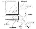
本発明の一実施例の構成を図1に示す。本実施例は、複数のAV機器における片方向リモコンシステムの例であり、AV機器であるテレビとビデオが隣接した場所にある場合の制御例である。リモコン装置からは、機器特定用の信号として可視光線を発光し、機器制御用の信号として赤外線を発光している。
【0021】
本実施例では、機器特定用の信号として可視光線を用いたが、可視のレーザー光等のユーザーが視覚的に認識可能なものを使ってもよい。また、機器制御用の信号として赤外線のほか無線などの不可視の信号を使ってもよい。なお、本実施例では、機器制御装置はテレビ・ビデオの機器内に設置されているが、機器制御装置は機器の外部にあってもよい。さらに、可視光線の出力装置には絞りがついていて、出力範囲が可変であってもよい。また、機器制御装置の受信判定部が可視光線を受信したことを、ユーザーに知らせるための表示や音声があってもよい。
【0022】
次に、上記構成によるリモコンシステムが実現されるハードウェアブロック回路について、図3と共に説明する。
【0023】
まず、ユーザーはユーザーインターフェース部11より可視光線の発光要求をする。入力された情報は、演算部12aにて解析を行い、機器特定用信号送信部13aに対して、可視光線の発光要求を行う。機器特定用信号発光部13aは、可視光線の発光を行う。
【0024】
次に、ユーザーは、制御を行いたい機器に対して、リモコン装置10から発光する可視光線が機器制御装置20の機器特定用信号受光部21aに当たるようにリモコン装置10を向ける。機器特定用信号受光部21aで可視光線を受信したか否かは、受信判定部22aにて判定され、演算部22cにおいて、機器制御用信号の受信待ち状態となる。
【0025】
次に、ユーザーは、機器に対して制御を行いたい内容をユーザーインターフェース部11より入力する。ユーザーインターフェース部11にて入力された情報は、演算部12aにて解析され、通信制御部12bに通信制御依頼を要求する。通信制御部12bでは、通信の制御を調停しながら、機器制御用信号送信部13bに赤外線の発光要求を行う。機器制御用信号送信部13bから発光された赤外線は、機器制御用信号受信部21bにて受信される。このとき、可視光線の出力範囲より赤外線の出力範囲の方が十分に大きいものとし、可視光線を受光している機器は、赤外線も必ず受光するものとする。機器制御用信号受信部21bで、受信された赤外線は通信制御部22bにて制御の調停を行い、演算部22cにて解析される。解析された結果、ユーザーが行いたい制御内容に基づき、機器制御部22dより機器の制御を行う。
【0026】
次に、上記のような構成の本リモコン装置10と本機器制御装置20の動作を図5・6に示すフローチャートに従って説明する。
【0027】
まず、リモコン装置10について説明を行う。最初に、ユーザーがユーザーインターフェース部11に対して処理要求を行うのを待つ(ステップS11)。ステップS11によって入力された要求が可視光線の発光要求であるかどうかを判定し、可視光線の発光要求でなければ、ステップ11に戻る(ステップS12)。可視光線の発光要求であれば、機器特定用信号送信部13aより可視光線の発光を行う(ステップS13)。ユーザーはここで、可視光線を制御したい機器制御装置20の機器特定用信号受信部21aに向ける。次に、リモコン装置10は、ユーザーがユーザーインターフェース部11に入力するのを待つ(ステップS14)。ユーザーから入力された情報が機器制御の要求であるかを判定し、機器制御の要求でなければステップS14に戻る(ステップS15)。もし、機器制御の要求であれば、制御内容を演算部22cにて解析を行い、機器制御部22dより機器の制御を行う(ステップS16)。次に、続けて機器の制御があるかどうかを判別し、続けて機器の制御を行う場合はステップS14に戻る(ステップS17)。続けて機器の制御がない場合は可視光線の発光処理を停止する(ステップS18)。
【0028】
次に、機器制御装置20について説明を行う。最初に、機器特定用信号受信部21aにて可視光線の受信待ちを行う(ステップS21)。受信判定部22aにて、可視光線を受信したか否かを判定し、可視光線を受信していなければ、ステップS21に戻る(ステップS22)。可視光線を受信していれば、機器制御用信号受信部21bに赤外線を受信しているか否かを判定し、赤外線を受信していなければステップS21へ戻る(ステップS23)。もし、赤外線を受信していれば、通信制御部22bのデータを演算部22cにて解析を行う(ステップS24)。演算部22cにて解析を行った結果に基づき、機器制御部22dより機器の制御を行う(ステップS25)。
【0029】
従って、請求項1から4の本実施例において、視覚的な遠隔操作が可能となり、特に、複数の遠隔操作が必要な機器が存在するAV機器に利用することができ、他の空調・照明機器などの遠隔操作を必要とする家電製品に広く応用することができる。
【0030】
(実施例2)
以下、本発明の請求項5から8に対応する実施例を図面により詳細に説明する。
【0031】
本発明の一実施例の構成を図2に示す。本実施例は、複数のAV機器における双方向リモコンシステムの例であり、AV機器であるテレビとビデオが隣接した場所にある場合の制御例である。リモコン装置からは、機器特定用の信号として可視光線を発光し、機器制御用の信号として赤外線を発光している。
【0032】
本実施例では、機器特定用の信号として可視光線を用いたが、可視のレーザー光等のユーザーが視覚的に認識可能なものを使ってもよい。また、機器制御用の信号として赤外線のほか無線などの不可視の信号を使ってもよい。なお、本実施例では、機器制御装置はテレビ・ビデオの機器内に設置されているが、機器制御装置は機器の外部にあってもよい。さらに、可視光線の出力装置には絞りがついていて、出力範囲が可変であってもよい。また、機器制御装置の受信判定部が可視光線を受信したことを、ユーザーに知らせるための表示や音声があってもよい。
【0033】
次に、上記構成によるリモコンシステムが実現されるハードウェアブロック回路について、図4と共に説明する。
【0034】
まず、ユーザーはユーザーインターフェース部31aより可視光線の発光要求をする。入力された情報は、演算部32aにて解析を行い、機器特定用信号送信部33aに対して、可視光線の発光要求を行う。機器特定用信号発光部33aは、可視光線の発光を行う。
【0035】
次に、ユーザーは、制御を行いたい機器に対して、リモコン装置30から発光する可視光線が機器制御装置40の機器特定用信号受光部41aに当たるようにリモコン装置40を向ける。機器特定用信号受光部41aで可視光線を受信したか否かは、受信判定部42aにて判定され、演算部42cにおいて、機器制御用信号の受信待ち状態となる。
【0036】
次に、ユーザーは、機器に対して制御を行いたい内容をユーザーインターフェース部31より入力する。ユーザーインターフェース部31にて入力された情報は、演算部32aにて解析され、通信制御部32bに通信制御依頼を要求する。通信制御部32bでは、通信の制御を調停しながら、機器制御用信号送信部33bに赤外線の発光要求を行う。機器制御用信号送信部33bから発光された赤外線は、機器制御用信号受信部41cにて受信される。このとき、可視光線の出力範囲より赤外線の出力範囲の方が十分に大きいものとし、可視光線を受光している機器は、赤外線も必ず受光するものとする。機器制御用信号受信部41cで、受信された赤外線は通信制御部42bにて制御の調停を行い、演算部42cにて解析される。解析された結果、ユーザーが行いたい制御内容に基づき、機器制御部42dより機器の制御を行う。この時、機器の状態や通信状況をリモコン装置31の表示部31bに行うために、機器制御用信号送信部41bから機器制御用信号受信部33cに赤外線を送信する。
【0037】
次に、上記のような構成の本リモコン装置30と本機器制御装置40の動作を図7・8に示すフローチャートに従って説明する。
【0038】
まず、リモコン装置30について説明を行う。最初に、ユーザーがユーザーインターフェース部31aに対して処理要求を行うのを待つ(ステップS31)。ステップS31によって入力された要求が可視光線の発光要求であるかどうかを判定し、可視光線の発光要求でなければ、ステップ31に戻る(ステップS32)。可視光線の発光要求であれば、機器特定用信号送信部33aより可視光線の発光を行う(ステップS33)。ユーザーはここで、可視光線を制御したい機器制御装置40の機器特定用信号受信部41aに向ける。次に、リモコン装置30は、ユーザーがユーザーインターフェース部31aに入力するか赤外線を受信するのを待つ(ステップS34)。ユーザーから入力された情報もしくは受信した赤外線が機器制御の要求であるかを判定し、機器制御の要求でなければステップS34に戻る(ステップS35)。もし、機器制御の要求であれば、表示部31bに制御内容を表示し、制御内容を演算部42cにて解析を行い、機器制御部42dより機器の制御を行う(ステップS36)。次に、続けて機器の制御があるかどうかを判別し、続けて機器の制御を行う場合はステップS34に戻る(ステップS37)。続けて機器の制御がない場合は可視光線の発光処理を停止する(ステップS38)。
【0039】
次に、機器制御装置40について説明を行う。最初に、機器特定用信号受信部41aにて可視光線の受信待ちを行う(ステップS41)。受信判定部42aにて、可視光線を受信したか否かを判定し、可視光線を受信していなければ、ステップS41に戻る(ステップS42)。可視光線を受信していれば、機器制御用信号受信部41cに赤外線を受信しているか否かを判定し、赤外線を受信していなければステップS46へ進む(ステップS43)。もし、赤外線を受信していれば、通信制御部42bのデータを演算部42cにて解析を行う(ステップS44)。演算部42cにて解析を行った結果に基づき、機器制御部42dより機器の制御を行う(ステップS45)。また、機器制御用信号受信部41bに赤外線を受信していない時、通信制御部42bに送信用データがあるかどうか判定し、送信データがなければ終了処理をする(ステップS46)。送信用データがあれば、機器制御用信号送信部41bより赤外線を発光し、送信用データがリモコン装置30へ送る(ステップS47)。
【0040】
従って、請求項1から4の本実施例において、視覚的な遠隔操作が可能となり、特に、複数の遠隔操作が必要な機器が存在するAV機器に利用することができ、他の空調・照明機器などの遠隔操作を必要とする家電製品に広く応用することができる。
【0041】
この発明に係るリモコン装置は、複数の機器を特定し、制御するリモコン装置であって、機器特定する指向性信号を送信する手段と、機器制御用信号を送信する手段と、を備えてなることによって、上記の目的を達成する。
【0042】
この発明に係る機器制御装置は 上述のリモコン装置によって遠隔操作される機器制御装置であって、前記指向性信号を受信する手段と、前記受信する手段によって指向性信号を受信したことを判別する手段と、前記機器制御用信号を受信する手段と、前記判別する手段で指向性信号を受信したことを判別したときに、前記機器制御用信号を解読する手段と、該解読する手段によって解読した前記機器制御用信号に基づいて機器の制御を行う手段と、を備えてなることによって上記の目的を達成する。
【0043】
この発明に係るリモコンシステムは、複数の機器制御装置と、これらの機器制御装置の遠隔操作を行うリモコン装置とを備えたリモコンシステムであって、前記リモコン装置が、少なくとも、機器特定する指向性信号を送信する手段と、機器制御用信号を送信する手段と、を備えてなり、前記機器制御装置が、少なくとも、前記指向性信号を受信する手段と、前記受信する手段によって指向性信号を受信したことを判別する手段と、前記機器制御用信号を受信する手段と、前記判別する手段で指向性信号を受信したことを判別したときに、前記機器制御用信号を解読する手段と、該解読する手段によって解読した前記機器制御用信号に基づいて機器の制御を行う手段と、を備えてなることによって上記の目的を達成する。
【0044】
この発明に係るリモコンシステム制御方法は、複数の機器制御装置と、これらの機器制御装置の遠隔操作を行うリモコン装置とを制御するリモコンシステム制御方法であって、前記リモコン装置を制御するプロセスが、少なくとも、機器特定する指向性信号を送信するステップと、機器制御用信号を送信するステップと、を備えてなり、前記機器制御装置を制御するプロセスが、少なくとも、前記指向性信号を受信するステップと、前記受信するステップによって指向性信号を受信したことを判別するステップと、前記機器制御用信号を受信するステップと、前記判別するステップで指向性信号を受信したことを判別したときに、前記機器制御用信号を解読するステップと、該解読するステップによって解読した前記機器制御用信号に基づいて機器の制御を行うステップと、を備えてなることによって、上記の目的を達成する。
【0045】
この発明に係るリモコン装置は、複数の機器を特定し、制御するリモコン装置であって、機器特定する指向性信号を送信する手段と、機器制御用信号を送受信する手段と、を備えてなることによって、上記の目的を達成する。
【0046】
この発明に係る機器制御装置は、上述のリモコン装置によって遠隔操作される機器制御装置であって、前記指向性信号を受信する手段と、前記受信する手段によって指向性信号を受信したことを判別する手段と、前記機器制御用信号を送受信する手段と、前記判別する手段で指向性信号を受信したことを判別したときに、前記機器制御用信号を解読する手段と、該解読する手段によって解読した前記機器制御用信号に基づいて機器の制御を行う手段と、を備えてなることによって上記の目的を達成する。
【0047】
この発明に係るリモコンシステムは、複数の機器制御装置とこれらの機器制御装置の遠隔操作を行うリモコン装置とを備えたリモコンシステムであって、前記リモコン装置が、少なくとも、機器特定する指向性信号を送信する手段と、機器制御用信号を送受信する手段と、を備えてなり、前記機器制御装置が、少なくとも、前記指向性信号を受信する手段と、前記受信する手段によって指向性信号を受信したことを判別する手段と、前記機器制御用信号を送受信する手段と、前記判別する手段で指向性信号を受信したことを判別したときに、前記機器制御用信号を解読する手段と、該解読する手段によって解読した前記機器制御用信号に基づいて機器の制御を行う手段と、を備えてなることによって上記の目的を達成する。
【0048】
この発明に係るリモコンシステム制御方法は、複数の機器制御装置と、これらの機器制御装置の遠隔操作を行うリモコン装置とを制御するリモコンシステム制御方法であって、前記リモコン装置を制御するプロセスが、少なくとも、機器特定する指向性信号を送信するステップと、機器制御用信号を送受信するステップと、を備えてなり、前記機器制御装置を制御するプロセスが、少なくとも、前記指向性信号を受信するステップと、前記受信するステップによって指向性信号を受信したことを判別するステップと、前記機器制御用信号を送受信するステップと、前記判別するステップで指向性信号を受信したことを判別したときに、前記機器制御用信号を解読するステップと、該解読するステップによって解読した前記機器制御用信号に基づいて機器の制御を行うステップと、を備えてなることによって、上記の目的を達成する。
【0049】
【発明の効果】
以上のように、本発明によれば、一つの共通リモコン操作にもかかわらず、確実・簡単・短時間にユーザーが本当に対象としたい機器を特定し、特定機器に対して確実に制御を行うことができるリモコンシステムを提供することができる。
【0050】
また、ユーザーが対象としたい機器を確実に特定できるので、リモコンに付属する表示部もしくはテレビなどの表示装置を必ずしも必要とせず、機器選択用の制御用ボタンを必要としないため、安価にリモコンシステムを構成することができる。
【0051】
さらに、従来、リモコン部にある複数の制御用ボタンから機器の特定を行なったり、リモコン表示部に表示されている機器からユーザーが操作したい機器を選択してから制御を行ったりしていたが、機器の方にリモコンを向けるだけで機器を特定することができるので、入力時の手間が省け簡単に短時間に操作することができるようになる。
【0052】
複数の機器から特定の機器の制御を行いたい場合、ユーザーが制御したい機器をいくつかの候補から選択するのでなく、リモコンを機器の方向にむけるだけで機器の制御が可能になる。直感的な機器指定をすることができるようになる。これに伴い、リモコン機器の操作手順の簡略化が可能になり、さらに、リモコン部の制御用ボタン数などを減少することができる。
【図面の簡単な説明】
【図1】 本発明の実施例1を示す構成図である。
【図2】 本発明の実施例2を示す構成図である。
【図3】 本発明における実施例1のハードウェアブロック回路図である。
【図4】 本発明における実施例2のハードウェアブロック回路図である。
【図5】 リモコン装置の実施例1の動作を示すフローチャートである。
【図6】 受信装置の実施例1の動作を示すフローチャートである。
【図7】 リモコン装置の実施例2の動作を示すフローチャートである。
【図8】 受信装置の実施例2の動作を示すフローチャートである。
【符号の説明】
10 リモコン装置
11 ユーザーインターフェース部
12 処理装置
13 送信部
20 受信装置
21 受信部
22 処理装置[0001]
BACKGROUND OF THE INVENTION
The present invention relates to an AV system such as a television receiver and its peripheral video equipment, and a remote control device, equipment control device for home appliances that require remote control such as a personal computer and its peripheral equipment, air conditioning equipment and lighting equipment, The present invention relates to a remote control system and a remote control system control method.
[0002]
[Prior art]
In recent years, AV systems such as television receivers and peripheral video equipment, personal computers and peripheral equipment, air conditioning equipment, and lighting equipment have become widespread, and these equipment are used for easy operation and remote operation. Is equipped with a remote control transmitter to help improve operability. However, these remote controls have to use separate remote control transmitters. If they increase, the remote location is troubled, you can search around when necessary, you do not know which remote control belongs to which device, A bug came out. The reason why you need to use separate remote controls is that if you can operate with the same remote control, both will move when you want to move one, so the remote control code is changed on purpose. However, this causes the aforementioned problems.
[0003]
In order to solve this problem, some remote control transmitters are provided with operation buttons of a plurality of devices. Some of these can run television and video, and some can even run to stereo. However, these remote controls can be used in different ways, such as when the number of devices that can be operated increases, the number of buttons increases and the remote control transmitter becomes larger, or there are too many buttons and you are wondering which button to press. There is bitterness.
[0004]
On the other hand, in order to increase the functions that can be operated without increasing the number of buttons, there is a method of displaying a list of functions to be operated on the screen and pressing the enter button in accordance with the cursor. An example is Japanese Patent Application Laid-Open No. 62-21379. In this prior application, various functions necessary for operation are displayed on the screen of the television receiver, the cursor is moved to that position, and when the operation is instructed, the function indicated by the cursor operates. However, this prior application operates many functions of one device with few buttons, and does not disclose reducing the number of operation buttons when a plurality of devices are combined.
[0005]
In addition, in a remote controller for controlling a plurality of AV devices, when a plurality of AV devices are controlled by a single remote controller, considering that the plurality of AV devices are adjacent to each other, a candidate device targeted on the remote control side And the user had to select the target device or had a button for selecting a device to be controlled in advance on the remote control. In addition, devices having the same remote control code cannot be individually controlled, and the newly added device has to be registered on the remote control side.
[0006]
[Problems to be solved by the invention]
In the prior art, an IR remote controller or the like is mainly used, and a relatively large range is targeted, and devices within the range are controlled by invisible light, radio, or the like. For this reason, when there are a plurality of devices in adjacent ranges, it is difficult for the user to specify the device that the user wants to control, and there is a possibility that the device that does not want to be controlled will operate.
[0007]
In addition, if there are multiple target devices, the display unit attached to the remote control or a display device such as a television must indicate that there are multiple target devices, and the user must select the target device from the target candidate devices. It takes time and effort.
[0008]
In order to solve the above-mentioned problems of the present invention, a single remote controller can be used to identify a device that a user really wants to be surely, easily, and in a short time, and to control only a specific device with certainty. The purpose is to provide a remote control system.
[0009]
[Means for Solving the Problems]
A remote control device according to the present invention is a remote control device for remotely operating a plurality of device control devices provided for each device in order to control a plurality of devices, The device control device is set in a state in which a device control signal for controlling the device can be decoded. Means for transmitting a directivity signal of visible light to the device control device; Said A device for transmitting a device control signal to the device control device, and a diaphragm for changing the output range of the visible light. The means for transmitting the visible light directivity signal starts emitting the visible light before the means for transmitting the device control signal transmits the device control signal, and transmits the device control signal. After the means for performing the transmission of the device control signal ends, the visible light emission ends. It is characterized by that.
[0010]
An apparatus control apparatus according to the present invention is an apparatus control apparatus remotely operated by the above-described remote control apparatus, Visible light Means for receiving a directional signal and said means for receiving Visible light Means for determining that a directional signal has been received; means for receiving the device control signal; and means for determining As a result of the determination, if the visible light is not received, waiting for the visible light is received, and if the visible light is received, It is characterized by comprising means for decoding the device control signal and means for controlling the device based on the device control signal decoded by the decoding means.
[0011]
A remote control system according to the present invention is a remote control system including a device control device provided for each device to control a plurality of devices, and a remote control device that performs remote control of the plurality of device control devices, The remote control device is at least: The device control device is set in a state in which a device control signal for controlling the device can be decoded. Means for transmitting a directivity signal of visible light to the device control device; Said Means for transmitting a device control signal to the device control device, and a diaphragm for changing the output range of the visible light, The means for transmitting the visible light directivity signal starts the emission of the visible light before the means for transmitting the device control signal transmits the device control signal, and transmits the device control signal. After the means finishes transmitting the device control signal, the visible light emission ends, The device control device is at least the Visible light Means for receiving a directional signal and said means for receiving Visible light Means for determining that a directional signal has been received; means for receiving the device control signal; and means for determining As a result of the determination, if the visible light is not received, waiting for the visible light is received, and if the visible light is received, It is characterized by comprising means for decoding the device control signal and means for controlling the device based on the device control signal decoded by the decoding means.
[0012]
A remote control system control method according to the present invention is a remote control system control method for controlling a device control device provided for each device to control a plurality of devices and a remote control device that performs a remote operation of the plurality of device control devices. And the process of controlling the remote control device is at least: The device control device is set in a state in which a device control signal for controlling the device can be decoded. Transmitting a directivity signal of visible light whose output range is limited by a diaphragm included in the remote control device, which is a signal, to the device control device; Said Transmitting a device control signal to the device control device, and In the step of transmitting the visible light directivity signal, the visible light emission is started before the step of transmitting the device control signal, and the step of transmitting the device control signal is completed. Stop emitting light, The process of controlling the device control device is at least the above Visible light Receiving a directional signal; and receiving the directional signal Visible light A step of determining that a directional signal has been received; a step of receiving the device control signal; and a step of determining. As a result of the determination, if the visible light is not received, waiting for the visible light is received, and if the visible light is received, A step of decoding the device control signal; and a step of controlling the device based on the device control signal decoded by the step of decoding.
[0013]
A remote control device according to the present invention is a remote control device for remotely operating a plurality of device control devices provided for each device in order to control a plurality of devices, The device control device is set in a state in which a device control signal for controlling the device can be decoded. Means for transmitting a directivity signal of visible light to the device control device; Said Means for transmitting a device control signal to the device control device, and means for receiving from the device control device information indicating that the device control device has received the directivity signal of visible light, and A means for receiving information includes a display unit for displaying the received information. The means for transmitting the visible light directivity signal starts emitting the visible light before the means for transmitting the device control signal transmits the device control signal, and transmits the device control signal. After the means for performing the transmission of the device control signal ends, the visible light emission ends. It is characterized by that.
[0014]
An apparatus control apparatus according to the present invention is an apparatus control apparatus remotely operated by the above-described remote control apparatus, Visible light Means for receiving a directional signal and said means for receiving Visible light Means for determining that a directional signal has been received, and information indicating that the visible light directional signal has been received when the determining means determines that the visible light directional signal has been received; Means for transmitting to the remote control device, means for receiving the device control signal, and means for determining As a result of the determination, if the visible light is not received, waiting for the visible light is received, and if the visible light is received, It is characterized by comprising means for decoding the device control signal and means for controlling the device based on the device control signal decoded by the decoding means.
[0015]
A remote control system according to the present invention is a remote control system including a device control device provided for each device to control a plurality of devices, and a remote control device that performs remote control of the plurality of device control devices, The remote control device is at least: The device control device is set in a state in which a device control signal for controlling the device can be decoded. Means for transmitting a directivity signal of visible light to the device control device; Said Means for transmitting a device control signal to the device control device; means for receiving from the device control device information indicating that the device control device has received the directivity signal of visible light; and receiving the information. And a display unit for displaying the received information. The means for transmitting the visible light directivity signal starts the emission of the visible light before the means for transmitting the device control signal transmits the device control signal, and transmits the device control signal. After the means finishes transmitting the device control signal, the visible light emission ends, The device control device is at least the Visible light Means for receiving a directional signal and said means for receiving Visible light Means for determining that a directional signal has been received, and information indicating that the visible light directional signal has been received when the determining means determines that the visible light directional signal has been received; Means for transmitting to the remote control device, means for receiving the device control signal, and means for determining As a result of the determination, if the visible light is not received, waiting for the visible light is received, and if the visible light is received, It is characterized by comprising means for decoding the device control signal and means for controlling the device based on the device control signal decoded by the decoding means.
[0016]
A remote control system control method according to the present invention is a remote control system control method for controlling a device control device provided for each device to control a plurality of devices and a remote control device that performs a remote operation of the plurality of device control devices. And the process of controlling the remote control device is at least: The device control device is set in a state in which a device control signal for controlling the device can be decoded. Transmitting a visible light directivity signal to the device control device; Said Transmitting a device control signal to the device control device; receiving from the device control device information indicating that the device control device has received the directivity signal of visible light; and receiving the information. Displaying the information received by the step of performing, In the step of transmitting the visible light directivity signal, the visible light emission is started before the step of transmitting the device control signal, and the step of transmitting the device control signal is completed. Stop emitting light, The process of controlling the device control device is at least the above Visible light Receiving a directional signal; and receiving the directional signal Visible light A step of determining that a directional signal has been received, and the determination In steps Transmitting the information indicating that the visible light directivity signal has been received to the remote control device when determining that the visible light directivity signal has been received; and receiving the device control signal; In the step of determining As a result of the determination, if the visible light is not received, waiting for the visible light is received, and if the visible light is received, A step of decoding the device control signal; and a step of controlling the device based on the device control signal decoded by the step of decoding.
[0017]
The operation of the present invention will be described below.
[0018]
By adding directional visible light to the remote control, the user can visually select a specific device to be controlled from a plurality of devices.
[0019]
DETAILED DESCRIPTION OF THE INVENTION
Example 1
Hereinafter, embodiments corresponding to claims 1 to 4 of the present invention will be described in detail with reference to the drawings.
[0020]
The configuration of one embodiment of the present invention is shown in FIG. The present embodiment is an example of a one-way remote control system in a plurality of AV devices, and is a control example in the case where a television as a AV device and a video are in adjacent locations. The remote controller emits visible light as a device specifying signal and emits infrared light as a device control signal.
[0021]
In this embodiment, visible light is used as the device specifying signal. However, visible laser light or the like that can be visually recognized by the user may be used. In addition to infrared, invisible signals such as wireless may be used as device control signals. In this embodiment, the device control device is installed in a television / video device, but the device control device may be provided outside the device. Further, the output device for visible light may have a diaphragm and the output range may be variable. Further, there may be a display or a sound for notifying the user that the reception determining unit of the device control apparatus has received visible light.
[0022]
Next, a hardware block circuit for realizing the remote control system having the above configuration will be described with reference to FIG.
[0023]
First, the user requests the
[0024]
Next, the user points the
[0025]
Next, the user inputs contents to be controlled with respect to the device from the
[0026]
Next, the operations of the
[0027]
First, the
[0028]
Next, the
[0029]
Therefore, in this embodiment of claims 1 to 4, visual remote operation is possible, and in particular, it can be used for AV equipment having a plurality of devices that require remote operation, and other air conditioning / lighting equipment. It can be widely applied to household appliances that require remote control.
[0030]
(Example 2)
Embodiments corresponding to claims 5 to 8 of the present invention will be described below in detail with reference to the drawings.
[0031]
The configuration of one embodiment of the present invention is shown in FIG. The present embodiment is an example of a bidirectional remote control system in a plurality of AV devices, and is a control example in the case where a television as a AV device and a video are in adjacent locations. The remote controller emits visible light as a device specifying signal and emits infrared light as a device control signal.
[0032]
In this embodiment, visible light is used as the device specifying signal. However, visible laser light or the like that can be visually recognized by the user may be used. In addition to infrared, invisible signals such as wireless may be used as device control signals. In this embodiment, the device control device is installed in a television / video device, but the device control device may be provided outside the device. Further, the output device for visible light may have a diaphragm and the output range may be variable. Further, there may be a display or a sound for notifying the user that the reception determining unit of the device control apparatus has received visible light.
[0033]
Next, a hardware block circuit for realizing the remote control system having the above configuration will be described with reference to FIG.
[0034]
First, the user issues a visible light emission request from the
[0035]
Next, the user directs the
[0036]
Next, the user inputs contents to be controlled with respect to the device from the
[0037]
Next, operations of the
[0038]
First, the
[0039]
Next, the
[0040]
Therefore, in this embodiment of claims 1 to 4, visual remote operation is possible, and in particular, it can be used for AV equipment having a plurality of devices that require remote operation, and other air conditioning / lighting equipment. It can be widely applied to household appliances that require remote control.
[0041]
A remote control device according to the present invention is a remote control device that specifies and controls a plurality of devices, and includes means for transmitting a directional signal for specifying devices and means for transmitting a device control signal. To achieve the above object.
[0042]
An apparatus control apparatus according to the present invention is an apparatus control apparatus that is remotely operated by the remote control device described above, and means for receiving the directional signal and means for determining that the directional signal has been received by the receiving means. And means for receiving the device control signal, and means for decoding the device control signal when it is determined that the directivity signal has been received by the means for determining, The above object is achieved by comprising means for controlling the equipment based on the equipment control signal.
[0043]
A remote control system according to the present invention is a remote control system comprising a plurality of device control devices and a remote control device that performs remote operation of these device control devices, wherein the remote control device at least specifies a device. And a means for transmitting a device control signal, wherein the device control apparatus receives at least the directivity signal by the means for receiving the directivity signal and the means for receiving. Means for determining, means for receiving the device control signal, means for decoding the device control signal when the determining means determines that a directional signal has been received, and the decoding The above object is achieved by comprising means for controlling the equipment based on the equipment control signal decoded by the means.
[0044]
A remote control system control method according to the present invention is a remote control system control method for controlling a plurality of device control devices and a remote control device that performs remote operation of these device control devices, and the process of controlling the remote control device includes: At least a step of transmitting a directional signal for specifying a device and a step of transmitting a device control signal, wherein the process of controlling the device control apparatus receives at least the directional signal; Determining that the directional signal has been received by the receiving step, receiving the device control signal, and determining that the directional signal has been received in the determining step; A step of decoding the control signal, and based on the device control signal decoded by the decoding step And performing control of the device, by becoming comprise, to achieve the above object.
[0045]
A remote control device according to the present invention is a remote control device that specifies and controls a plurality of devices, and includes means for transmitting a directional signal for specifying devices and means for transmitting and receiving a device control signal. To achieve the above object.
[0046]
A device control device according to the present invention is a device control device that is remotely operated by the remote control device described above, and determines that the directional signal is received by the means for receiving the directional signal and the means for receiving. Means, means for transmitting / receiving the device control signal, and means for decoding the device control signal when it is determined that the directional signal is received by the means for determining, The above object is achieved by comprising means for controlling the device based on the device control signal.
[0047]
A remote control system according to the present invention is a remote control system including a plurality of device control devices and a remote control device that performs remote control of these device control devices, wherein the remote control device transmits at least a directional signal that identifies a device. Means for transmitting, and means for transmitting and receiving a device control signal, wherein the device control apparatus has received the directional signal by at least the means for receiving the directional signal and the means for receiving. Means for transmitting / receiving the device control signal, means for decoding the device control signal when the determining means determines that a directional signal has been received, and means for decoding Means for controlling the device based on the device control signal decoded in step (1).
[0048]
A remote control system control method according to the present invention is a remote control system control method for controlling a plurality of device control devices and a remote control device that performs remote operation of these device control devices, and the process of controlling the remote control device includes: At least a step of transmitting a directional signal for specifying a device and a step of transmitting and receiving a device control signal, wherein the process of controlling the device control device receives at least the directional signal; Determining that the directivity signal has been received by the receiving step, transmitting / receiving the device control signal, and determining that the directivity signal has been received in the determining step; A step of decoding the control signal, and based on the device control signal decoded by the decoding step. And performing control of equipment have, by becoming comprise, to achieve the above object.
[0049]
【The invention's effect】
As described above, according to the present invention, it is possible to identify a device that a user really wants to target in a reliable, simple and short time regardless of one common remote control operation, and to control the specified device with certainty. It is possible to provide a remote control system that can
[0050]
In addition, since the device that the user wants to target can be reliably identified, a display unit attached to the remote control or a display device such as a television is not necessarily required, and a control button for device selection is not required, so the remote control system is inexpensive. Can be configured.
[0051]
Furthermore, in the past, devices were identified from a plurality of control buttons on the remote control unit, or control was performed after selecting a device that the user wanted to operate from the devices displayed on the remote control display unit, Since the device can be specified simply by pointing the remote control at the device, it is possible to easily perform the operation in a short time without the trouble of inputting.
[0052]
When it is desired to control a specific device from a plurality of devices, the user can control the device only by pointing the remote control in the direction of the device, rather than selecting a device to be controlled from several candidates. Intuitive device designation will be possible. Accordingly, the operation procedure of the remote control device can be simplified, and the number of control buttons on the remote control unit can be reduced.
[Brief description of the drawings]
FIG. 1 is a configuration diagram showing Embodiment 1 of the present invention.
FIG. 2 is a configuration diagram showing Embodiment 2 of the present invention.
FIG. 3 is a hardware block circuit diagram according to the first embodiment of the present invention.
FIG. 4 is a hardware block circuit diagram of Embodiment 2 of the present invention.
FIG. 5 is a flowchart showing the operation of the first embodiment of the remote control device.
FIG. 6 is a flowchart illustrating the operation of the receiving apparatus according to the first exemplary embodiment.
FIG. 7 is a flowchart showing the operation of the second embodiment of the remote control device.
FIG. 8 is a flowchart illustrating an operation of the receiving apparatus according to the second exemplary embodiment.
[Explanation of symbols]
10 Remote control device
11 User interface
12 Processing equipment
13 Transmitter
20 Receiver
21 Receiver
22 Processing equipment
Claims (8)
前記機器制御装置を、機器を制御するための機器制御用信号を解読可能な状態にする可視光の指向性信号を前記機器制御装置に送信する手段と、
前記機器制御用信号を前記機器制御装置に送信する手段とを備えるとともに、
前記可視光の出力範囲を変更する絞りを備え、
前記可視光の指向性信号を送信する手段は、前記機器制御用信号を送信する手段が前記機器制御用信号を送信する前に前記可視光の発光を開始し、前記機器制御用信号を送信する手段が前記機器制御用信号の送信を終了した後で、前記可視光の発光を終了することを特徴とするリモコン装置。A remote control device for remotely operating a plurality of device control devices provided for each device in order to control a plurality of devices,
Means for transmitting to the device control device a directional signal of visible light that makes the device control device decodable a device control signal for controlling the device;
Provided with a means for transmitting the device control signal to the device control apparatus,
A diaphragm for changing the output range of the visible light ,
The means for transmitting the visible light directivity signal starts the emission of the visible light before the means for transmitting the device control signal transmits the device control signal, and transmits the device control signal. A remote control device characterized in that after the means finishes transmitting the device control signal, the visible light emission ends .
前記可視光の指向性信号を受信する手段と、
前記受信する手段によって可視光の指向性信号を受信したことを判別する手段と、
前記機器制御用信号を受信する手段と、
前記判別する手段の判別の結果、前記可視光を受信しなければ、前記可視光の受信を待ち、前記可視光を受信していれば、前記機器制御用信号を解読する手段と、
該解読する手段によって解読した前記機器制御用信号に基づいて機器の制御を行う手段と、を備えてなることを特徴とする機器制御装置。A device control device remotely operated by the remote control device according to claim 1,
Means for receiving the visible light directivity signal;
Means for determining that a directional signal of visible light has been received by the means for receiving;
Means for receiving the device control signal;
If it is determined in the means for the determination, if receiving the visible light, waits for reception of the visible light, if receiving the visible light, and means for decrypting the device control signals,
And a device for controlling the device based on the device control signal decoded by the decoding means.
前記リモコン装置は、少なくとも、
前記機器制御装置を、機器を制御するための機器制御用信号を解読可能な状態にする可視光の指向性信号を前記機器制御装置に送信する手段と、
前記機器制御用信号を前記機器制御装置に送信する手段と、
前記可視光の出力範囲を変更する絞りとを備え、
前記可視光の指向性信号を送信する手段は、前記機器制御用信号を送信する手段が前記機器制御用信号を送信する前に前記可視光の発光を開始し、前記機器制御用信号を送信する手段が前記機器制御用信号の送信を終了した後で、前記可視光の発光を終了し、
前記機器制御装置は、少なくとも、
前記可視光の指向性信号を受信する手段と、
前記受信する手段によって可視光の指向性信号を受信したことを判別する手段と、
前記機器制御用信号を受信する手段と、
前記判別する手段の判別の結果、前記可視光を受信しなければ、前記可視光の受信を待ち、前記可視光を受信していれば、前記機器制御用信号を解読する手段と、
該解読する手段によって解読した前記機器制御用信号に基づいて機器の制御を行う手段と、を備えてなることを特徴とするリモコンシステム。A remote control system comprising a device control device provided for each device to control a plurality of devices, and a remote control device that performs remote control of the plurality of device control devices,
The remote control device is at least:
Means for transmitting to the device control device a directional signal of visible light that makes the device control device decodable a device control signal for controlling the device;
Means for transmitting the device control signal to the device control apparatus,
A diaphragm for changing the output range of the visible light,
The means for transmitting the visible light directivity signal starts the emission of the visible light before the means for transmitting the device control signal transmits the device control signal, and transmits the device control signal. After the means finishes transmitting the device control signal, the visible light emission ends,
The device control device is at least
Means for receiving the visible light directivity signal;
Means for determining that a directional signal of visible light has been received by the means for receiving;
Means for receiving the device control signal;
If it is determined in the means for the determination, if receiving the visible light, waits for reception of the visible light, if receiving the visible light, and means for decrypting the device control signals,
Means for controlling a device based on the device control signal decoded by the decoding means.
前記リモコン装置を制御するプロセスは、少なくとも、
前記機器制御装置を、機器を制御するための機器制御用信号を解読可能な状態にする信号である、前記リモコン装置が備える絞りによって出力範囲が制限された可視光の指向性信号を前記機器制御装置に送信するステップと、
前記機器制御用信号を前記機器制御装置に送信するステップと、を備えてなり、
前記可視光の指向性信号を送信するステップでは、前記機器制御用信号を送信するステップより前に前記可視光の発光を開始し、前記機器制御用信号を送信するステップが終了した後で前記可視光の発光を終了し、
前記機器制御装置を制御するプロセスは、少なくとも、
前記可視光の指向性信号を受信するステップと、
前記受信するステップによって可視光の指向性信号を受信したことを判別するステップと、
前記機器制御用信号を受信するステップと、
前記判別するステップでの判別の結果、前記可視光を受信しなければ、前記可視光の受信を待ち、前記可視光を受信していれば、前記機器制御用信号を解読するステップと、
該解読するステップによって解読した前記機器制御用信号に基づいて機器の制御を行うステップと、を備えてなることを特徴とするリモコンシステム制御方法。A remote control system control method for controlling a device control device provided for each device to control a plurality of devices, and a remote control device for performing remote operation of the plurality of device control devices,
The process of controlling the remote control device is at least:
The device control device controls a device for controlling a visible light directivity signal whose output range is limited by a diaphragm included in the remote control device, which is a signal for enabling a device control signal for controlling the device to be decoded. Transmitting to the device;
Be provided with, and transmitting the device control signal to the device control apparatus,
In the step of transmitting the visible light directivity signal, the visible light emission is started before the step of transmitting the device control signal, and the step of transmitting the device control signal is completed. Stop emitting light,
The process of controlling the device control device is at least:
Receiving the visible light directional signal;
Determining that a directional signal of visible light has been received by the receiving step;
Receiving the device control signal;
As a result of determination in the determining step, if the visible light is not received, waiting for reception of the visible light; if receiving the visible light, decoding the device control signal; and
A remote control system control method comprising: controlling the device based on the device control signal decoded in the decoding step.
前記機器制御装置を、機器を制御するための機器制御用信号を解読可能な状態にする可視光の指向性信号を前記機器制御装置に送信する手段と、
前記機器制御用信号を前記機器制御装置に送信する手段と、
前記機器制御装置から、該機器制御装置が前記可視光の指向性信号を受信したことを示す情報を受信する手段とを備えるとともに、
前記情報を受信する手段が受信した情報を表示する表示部を備え、
前記可視光の指向性信号を送信する手段は、前記機器制御用信号を送信する手段が前記機器制御用信号を送信する前に前記可視光の発光を開始し、前記機器制御用信号を送信する手段が前記機器制御用信号の送信を終了した後で、前記可視光の発光を終了することを特徴とするリモコン装置。A remote control device for remotely operating a plurality of device control devices provided for each device in order to control a plurality of devices,
Means for transmitting to the device control device a directional signal of visible light that makes the device control device decodable a device control signal for controlling the device;
Means for transmitting the device control signal to the device control apparatus,
Means for receiving from the device control device information indicating that the device control device has received the directional signal of visible light, and
A display unit for displaying the information received by the means for receiving the information ;
The means for transmitting the visible light directivity signal starts the emission of the visible light before the means for transmitting the device control signal transmits the device control signal, and transmits the device control signal. A remote control device characterized in that after the means finishes transmitting the device control signal, the visible light emission ends .
前記可視光の指向性信号を受信する手段と、
前記受信する手段によって可視光の指向性信号を受信したことを判別する手段と、
前記判別する手段が前記可視光の指向性信号を受信したと判別したときに、前記可視光の指向性信号を受信したことを示す情報を前記リモコン装置に送信する手段と、
前記機器制御用信号を受信する手段と、
前記判別する手段の判別の結果、前記可視光を受信しなければ、前記可視光の受信を待ち、前記可視光を受信していれば、前記機器制御用信号を解読する手段と、
該解読する手段によって解読した前記機器制御用信号に基づいて機器の制御を行う手段と、を備えてなることを特徴とする機器制御装置。A device control device remotely operated by the remote control device according to claim 5,
Means for receiving the visible light directivity signal;
Means for determining that a directional signal of visible light has been received by the means for receiving;
Means for transmitting to the remote control device information indicating that the visible light directivity signal has been received when the determining means determines that the visible light directivity signal has been received;
Means for receiving the device control signal;
If it is determined in the means for the determination, if receiving the visible light, waits for reception of the visible light, if receiving the visible light, and means for decrypting the device control signals,
And a device for controlling the device based on the device control signal decoded by the decoding means.
前記リモコン装置は、少なくとも、
前記機器制御装置を、機器を制御するための機器制御用信号を解読可能な状態にする可視光の指向性信号を前記機器制御装置に送信する手段と、
前記機器制御用信号を前記機器制御装置に送信する手段と、
前記機器制御装置から、該機器制御装置が前記可視光の指向性信号を受信したことを示す情報を受信する手段と、
前記情報を受信する手段が受信した情報を表示する表示部とを備えてなり、
前記可視光の指向性信号を送信する手段は、前記機器制御用信号を送信する手段が前記機器制御用信号を送信する前に前記可視光の発光を開始し、前記機器制御用信号を送信する手段が前記機器制御用信号の送信を終了した後で、前記可視光の発光を終了し、
前記機器制御装置は、少なくとも、
前記可視光の指向性信号を受信する手段と、
前記受信する手段によって可視光の指向性信号を受信したことを判別する手段と、
前記判別する手段が前記可視光の指向性信号を受信したと判別したときに、前記可視光の指向性信号を受信したことを示す情報を前記リモコン装置に送信する手段と、
前記機器制御用信号を受信する手段と、
前記判別する手段の判別の結果、前記可視光を受信しなければ、前記可視光の受信を待ち、前記可視光を受信していれば、前記機器制御用信号を解読する手段と、
該解読する手段によって解読した前記機器制御用信号に基づいて機器の制御を行う手段と、を備えてなることを特徴とするリモコンシステム。A remote control system comprising a device control device provided for each device to control a plurality of devices, and a remote control device that performs remote control of the plurality of device control devices,
The remote control device is at least:
Means for transmitting to the device control device a directional signal of visible light that makes the device control device decodable a device control signal for controlling the device;
Means for transmitting the device control signal to the device control apparatus,
Means for receiving from the device control device information indicating that the device control device has received the directional signal of visible light;
A means for receiving the information comprises a display unit for displaying the received information,
The means for transmitting the visible light directivity signal starts the emission of the visible light before the means for transmitting the device control signal transmits the device control signal, and transmits the device control signal. After the means finishes transmitting the device control signal, the visible light emission ends,
The device control device is at least
Means for receiving the visible light directivity signal;
Means for determining that a directional signal of visible light has been received by the means for receiving;
Means for transmitting to the remote control device information indicating that the visible light directivity signal has been received when the determining means determines that the visible light directivity signal has been received;
Means for receiving the device control signal;
If it is determined in the means for the determination, if receiving the visible light, waits for reception of the visible light, if receiving the visible light, and means for decrypting the device control signals,
Means for controlling a device based on the device control signal decoded by the decoding means.
前記リモコン装置を制御するプロセスは、少なくとも、
前記機器制御装置を、機器を制御するための機器制御用信号を解読可能な状態にする可視光の指向性信号を前記機器制御装置に送信するステップと、
前記機器制御用信号を前記機器制御装置に送信するステップと、
前記機器制御装置から、該機器制御装置が前記可視光の指向性信号を受信したことを示す情報を受信するステップと、
前記情報を受信するステップによって受信された情報を表示するステップとを備えてなり、
前記可視光の指向性信号を送信するステップでは、前記機器制御用信号を送信するステップより前に前記可視光の発光を開始し、前記機器制御用信号を送信するステップが終了した後で前記可視光の発光を終了し、
前記機器制御装置を制御するプロセスは、少なくとも、
前記可視光の指向性信号を受信するステップと、
前記受信するステップによって可視光の指向性信号を受信したことを判別するステップと、
前記判別するステップで前記可視光の指向性信号を受信したと判別したときに、前記可視光の指向性信号を受信したことを示す情報を前記リモコン装置に送信するステップと、
前記機器制御用信号を受信するステップと、
前記判別するステップでの判別の結果、前記可視光を受信しなければ、前記可視光の受信を待ち、前記可視光を受信していれば、前記機器制御用信号を解読するステップと、
該解読するステップによって解読した前記機器制御用信号に基づいて機器の制御を行うステップと、を備えてなることを特徴とするリモコンシステム制御方法。A remote control system control method for controlling a device control device provided for each device to control a plurality of devices, and a remote control device for performing remote operation of the plurality of device control devices,
The process of controlling the remote control device is at least:
Transmitting the directional signal of visible light to the device control device to make the device control device readable the device control signal for controlling the device; and
Transmitting the device control signal to the device control apparatus,
Receiving from the device control device information indicating that the device control device has received the directional signal of visible light;
Displaying the information received by the step of receiving the information,
In the step of transmitting the visible light directivity signal, the visible light emission is started before the step of transmitting the device control signal, and the step of transmitting the device control signal is completed. Stop emitting light,
The process of controlling the device control device is at least:
Receiving the visible light directional signal;
Determining that a directional signal of visible light has been received by the receiving step;
Sending When it is determined that it has received the directional signal of the visible light in the step, the information indicating reception of the directional signal in the visible light to the remote controller to the determination,
Receiving the device control signal;
As a result of determination in the determining step, if the visible light is not received, waiting for reception of the visible light; if receiving the visible light, decoding the device control signal; and
A remote control system control method comprising: controlling the device based on the device control signal decoded in the decoding step.
Priority Applications (1)
| Application Number | Priority Date | Filing Date | Title |
|---|---|---|---|
| JP11795098A JP3989619B2 (en) | 1998-04-28 | 1998-04-28 | Remote control device, device control device, remote control system, and remote control system control method |
Applications Claiming Priority (1)
| Application Number | Priority Date | Filing Date | Title |
|---|---|---|---|
| JP11795098A JP3989619B2 (en) | 1998-04-28 | 1998-04-28 | Remote control device, device control device, remote control system, and remote control system control method |
Publications (2)
| Publication Number | Publication Date |
|---|---|
| JPH11312009A JPH11312009A (en) | 1999-11-09 |
| JP3989619B2 true JP3989619B2 (en) | 2007-10-10 |
Family
ID=14724258
Family Applications (1)
| Application Number | Title | Priority Date | Filing Date |
|---|---|---|---|
| JP11795098A Expired - Fee Related JP3989619B2 (en) | 1998-04-28 | 1998-04-28 | Remote control device, device control device, remote control system, and remote control system control method |
Country Status (1)
| Country | Link |
|---|---|
| JP (1) | JP3989619B2 (en) |
Families Citing this family (3)
| Publication number | Priority date | Publication date | Assignee | Title |
|---|---|---|---|---|
| JP5399883B2 (en) * | 2009-12-21 | 2014-01-29 | パナソニック株式会社 | Lighting system |
| JP5286310B2 (en) * | 2010-03-15 | 2013-09-11 | 株式会社カスト | Lighting device adjustment device |
| WO2014188582A1 (en) * | 2013-05-24 | 2014-11-27 | Necディスプレイソリューションズ株式会社 | Display apparatus, remote control apparatus, remote operation system, control method, and remote operation method |
-
1998
- 1998-04-28 JP JP11795098A patent/JP3989619B2/en not_active Expired - Fee Related
Also Published As
| Publication number | Publication date |
|---|---|
| JPH11312009A (en) | 1999-11-09 |
Similar Documents
| Publication | Publication Date | Title |
|---|---|---|
| US5949351A (en) | System and method for bi-directional transmission of information between a remote controller and target systems | |
| US9866892B2 (en) | IR pairing for RF4CE remote controls | |
| US9355557B2 (en) | Universal remote controller and remote control method thereof | |
| EP3192218B1 (en) | Terminal for internet of things and operation method of the same | |
| US8643791B2 (en) | Information communication system, information processing apparatus, information communication program, and information communication method | |
| KR20110024435A (en) | Controlling device, controlled device, control system, and control authority providing method | |
| KR101588595B1 (en) | AN INTEGRATED REMOTE CONTROLLER SUPPORTING INTERNET OF THINGS(IoT) AND THE CONTROL METHOD THEREOF | |
| KR20120131765A (en) | Display device, method for remotely controlling display device | |
| KR101143601B1 (en) | System and method for a way to exchange digital contents among heterogeneous devices | |
| US20050185102A1 (en) | Single touch launch of remote applications over video | |
| US20120026409A1 (en) | Electronic Device and Remote-Control Method | |
| JP2009010486A (en) | Apparatus controller, apparatus control system, apparatus control method and program | |
| WO2009026310A1 (en) | Method and apparatus for controlled device selection by a portable electronic device | |
| JP3989619B2 (en) | Remote control device, device control device, remote control system, and remote control system control method | |
| US20040075777A1 (en) | Function control apparatus using remote control and method of controlling the same | |
| JP2999678B2 (en) | Remote control method, remote control system, remote control, and controlled device | |
| JP2008311958A (en) | Cellular phone | |
| US20060279584A1 (en) | AV network system and display device-side subsystem included in the same system | |
| JP2002538706A (en) | Remote control unit and system | |
| JP2000315959A (en) | Information receiver and information terminal | |
| JP2001100871A5 (en) | Computer equipment | |
| KR101833789B1 (en) | Image processing apparatus and external device controlling method using the same | |
| JP2007221466A (en) | Reservation system, method and program, and portable terminal device | |
| KR101214294B1 (en) | Home networking method using light signal and system thereof | |
| KR100714552B1 (en) | A method for positioning remote controller |
Legal Events
| Date | Code | Title | Description |
|---|---|---|---|
| A131 | Notification of reasons for refusal |
Free format text: JAPANESE INTERMEDIATE CODE: A131 Effective date: 20070123 |
|
| A521 | Written amendment |
Free format text: JAPANESE INTERMEDIATE CODE: A523 Effective date: 20070315 |
|
| RD02 | Notification of acceptance of power of attorney |
Free format text: JAPANESE INTERMEDIATE CODE: A7422 Effective date: 20070315 |
|
| A131 | Notification of reasons for refusal |
Free format text: JAPANESE INTERMEDIATE CODE: A131 Effective date: 20070508 |
|
| A521 | Written amendment |
Free format text: JAPANESE INTERMEDIATE CODE: A523 Effective date: 20070618 |
|
| TRDD | Decision of grant or rejection written | ||
| A01 | Written decision to grant a patent or to grant a registration (utility model) |
Free format text: JAPANESE INTERMEDIATE CODE: A01 Effective date: 20070717 |
|
| A61 | First payment of annual fees (during grant procedure) |
Free format text: JAPANESE INTERMEDIATE CODE: A61 Effective date: 20070718 |
|
| FPAY | Renewal fee payment (event date is renewal date of database) |
Free format text: PAYMENT UNTIL: 20100727 Year of fee payment: 3 |
|
| R150 | Certificate of patent or registration of utility model |
Free format text: JAPANESE INTERMEDIATE CODE: R150 |
|
| LAPS | Cancellation because of no payment of annual fees |