JP3985147B2 - Image processing apparatus, image processing method, and medium on which image processing program is recorded - Google Patents
Image processing apparatus, image processing method, and medium on which image processing program is recorded Download PDFInfo
- Publication number
- JP3985147B2 JP3985147B2 JP2002178178A JP2002178178A JP3985147B2 JP 3985147 B2 JP3985147 B2 JP 3985147B2 JP 2002178178 A JP2002178178 A JP 2002178178A JP 2002178178 A JP2002178178 A JP 2002178178A JP 3985147 B2 JP3985147 B2 JP 3985147B2
- Authority
- JP
- Japan
- Prior art keywords
- luminance
- image processing
- conversion
- distribution
- image
- Prior art date
- Legal status (The legal status is an assumption and is not a legal conclusion. Google has not performed a legal analysis and makes no representation as to the accuracy of the status listed.)
- Expired - Fee Related
Links
- 238000012545 processing Methods 0.000 title claims description 90
- 238000003672 processing method Methods 0.000 title claims description 8
- 238000009826 distribution Methods 0.000 claims description 229
- 238000006243 chemical reaction Methods 0.000 claims description 119
- 230000003595 spectral effect Effects 0.000 claims 1
- 235000019557 luminance Nutrition 0.000 description 274
- 238000000034 method Methods 0.000 description 36
- 230000008569 process Effects 0.000 description 24
- 238000010586 diagram Methods 0.000 description 21
- 238000012937 correction Methods 0.000 description 14
- 238000000605 extraction Methods 0.000 description 14
- 238000005070 sampling Methods 0.000 description 11
- 239000003086 colorant Substances 0.000 description 10
- 238000001228 spectrum Methods 0.000 description 9
- 238000007792 addition Methods 0.000 description 5
- 230000008859 change Effects 0.000 description 5
- 238000001514 detection method Methods 0.000 description 5
- 239000011159 matrix material Substances 0.000 description 4
- 230000002708 enhancing effect Effects 0.000 description 3
- 238000004891 communication Methods 0.000 description 2
- 230000000694 effects Effects 0.000 description 2
- 238000010422 painting Methods 0.000 description 2
- 230000009466 transformation Effects 0.000 description 2
- 206010001854 Altered state of consciousness Diseases 0.000 description 1
- 241000519995 Stachys sylvatica Species 0.000 description 1
- 230000002411 adverse Effects 0.000 description 1
- 230000008901 benefit Effects 0.000 description 1
- 238000005282 brightening Methods 0.000 description 1
- 230000006835 compression Effects 0.000 description 1
- 238000007906 compression Methods 0.000 description 1
- 239000012141 concentrate Substances 0.000 description 1
- 238000005520 cutting process Methods 0.000 description 1
- 238000002474 experimental method Methods 0.000 description 1
- 239000000284 extract Substances 0.000 description 1
- 239000004065 semiconductor Substances 0.000 description 1
- 238000003860 storage Methods 0.000 description 1
- 230000008685 targeting Effects 0.000 description 1
- 238000009966 trimming Methods 0.000 description 1
Images


Description
【0001】
【発明の属する技術分野】
本発明は、画像処理装置、画像処理方法および画像処理プログラムを記録した媒体に関し、特に、画像データのコントラストを処理する画像処理装置、画像処理方法および画像処理プログラムを記録した媒体に関する。
【0002】
【従来の技術】
従来、この種の画像処理装置として、特公平7−66318号公報に開示されたものが知られている。
【0003】
同公報に示す画像処理装置では、変換元の輝度yに対して変換後の輝度y’の関係を(1)式のように対応付け、操作者が選択したパラメータaあるいはパラメータbに基づいて画像データの輝度を変換している。これにより、コントラストの弱い画像データについてコントラストを強調した画像が得られる。
【0004】
y’=ay+b …(1)
【0005】
【発明が解決しようとする課題】
上述した従来の画像処理装置においては、予めコントラストの強弱の程度を変えた複数の設定を用意しておき、これを切り換えている。従って、現実の画像データに対応した最も好適なものを自動的に適用するということはできなかった。特に、(1)式に基づいて変化させる場合には全体が明るい画像であれば明るさが強調されるだけの結果となったり、全体が暗い画像であれば暗さが強調されるだけの結果となったりすることもあった。
【0006】
また、コントラストの強弱はテレビジョンなどでも操作可能なものでありながら、各画像において最適な強調を実行するといった自動化ができなかった。
【0007】
本発明は、上記課題にかんがみてなされたもので、コントラストの自動調整が可能な画像処理装置、画像処理方法および画像処理プログラムを記録した媒体の提供を目的とする。
【0008】
【課題を解決するための手段】
上記目的を達成するため、複数の画素からなる画像の画像データに対して所定の画像処理を行う画像処理装置であって、各画素での輝度に基づいて全体としての輝度分布を集計し、集計された輝度分布における実際の端部から所定分布割合だけ内側部分を端部とみなした輝度分布が当該画像データの取りうる有効な輝度範囲に広く分散するように上記画像データにおける各画素の輝度の情報を変換する構成としてもよい。
【0009】
上記構成においては、各画素での輝度に基づいて全体としての輝度分布を集計し、集計された輝度分布における実際の端部から所定分布割合だけ内側部分を端部とみなした輝度分布が当該画像データの取りうる有効な輝度範囲に広く分散するように上記画像データにおける各画素の輝度の情報を変換する。すなわち、画像データが画像をドットマトリクス状の画素に分解して各画素の情報を表している場合に、同画像データにおける輝度分布を求めることにより、画像データにおけるコントラストの幅というようなものをある程度数値化でき、数値化できた上で再現可能な範囲に対応して当該分布を拡大させる。
【0010】
むろん数値化といっても必ずしも具体的な数値が必要なわけではなく、その処理過程において数値として扱っても良いし、信号の大きさとして扱うようなことも可能である。
請求項1にかかる発明は、複数の画素からなる画像の画像データに対して所定の画像処理を行う画像処理装置であって、各画素での輝度に基づいて全体としての輝度分布を集計し、集計された輝度分布における実際の端部から所定分布割合だけ内側部分を端部とみなした輝度分布を検出する輝度分布検出手段と、上記検出された上記輝度分布を上記画像データの取りうる有効な輝度範囲において拡大する拡大率を検出し、同拡大率を利用して上記画像データにおける各画素の輝度の情報を変換する画像データ変換手段とを具備する構成としてある。
【0011】
所定画像の画像データを扱う上でその輝度分布を求めるため、輝度分布検出手段は各画素での輝度に基づいて全体としての輝度分布を集計し、集計された輝度分布における実際の端部から所定分布割合だけ内側部分を端部とみなした輝度分布を検出する。そして、この検出された輝度分布を利用して画像データ変換手段は、当該画像データの取りうる有効な輝度範囲において輝度分布を拡大する拡大率を検出し、同拡大率を利用して上記画像データにおける各画素の輝度の情報を変換する。
【0012】
すなわち、画素単位での画像データの輝度分布を求めれば最も明るい輝度から最も暗い輝度までのいわゆるコントラストの幅が判別でき、再現可能な輝度の幅の範囲と対比すればコントラストの拡大率が判定できるので、後はその拡大率となるようにして輝度分布を拡大させれば良くなる。例えば、各画素での輝度に基づいて全体としての輝度分布を集計した後、集計された輝度分布が当該画像データの取りうる有効な輝度範囲に広く分散していない場合に、上記輝度分布が同輝度範囲に広く分散するように上記画像データにおける各画素の輝度の情報を変換する。
【0013】
輝度分布を拡大する手法はいくつが可能であり、画像データの輝度分布が可能な範囲内で拡大されるようにすればよい。その要点を説明すれば、検出された輝度分布の統計的な幅と再現可能な輝度範囲の幅とを比較して拡大可能な程度を拡大率として求めるとともに、拡大された輝度分布の上端と下端がこの輝度範囲内に収まるようにするための調整値を求め、各画素の輝度を個別に修正するということである。この具体的な一例として、請求項2にかかる発明は、請求項1に記載の画像処理装置において、上記画像データ変換手段は、再現可能な輝度の範囲をyrange としたときに、変換前の輝度yと輝度の分布範囲の最大値ymax と最小値ymin から変換先の輝度Yを次式に基づいて求める構成としてある。
【0014】
Y=ay+b …(2)
ただし
a=yrange/(ymax−ymin) …(3)
b=−a・ymin …(4)
また、上記変換式にてY<0ならばY=0とし、Y>yrangeならばY=yrangeとする。
【0015】
この変換はいわゆる線形の拡大であり、変換式自体は従来のものと同様であるものの、そのパラメータが画像データ変換手段によって選定されることに意義がある。bの選択に関わらず、y=yminの場合にY=0となり、y=ymaxの場合にY=yrangeとなる。そして、再現可能な輝度の範囲であるyrangeの範囲内で輝度分布が一様に広がることになる。なお、この例においては、いわゆる狭義の線形変換であり、むろんこれに限られる必要はなく、広義の非線形変換を実施することも可能である。また、当該変換式は一例に過ぎず同意義の変換式であっても適用可能であることはいうまでもない。
【0016】
また、コントラストを広げただけでは全体に明るかったり暗かったりするというような場合に対応できないこともあり、画像データ変換手段は、変換元の輝度yの最大分布輝度を求めるとともに、同最大分布輝度の所属範囲に基づくγ補正で変換先の輝度Yを求める構成としてもよい。
【0017】
画像データが全体的に明るいか否かを判定する手法として、変換元の輝度yの最大分布輝度を利用し、この最大分布輝度が明るい側にあればγ補正で全体的に暗めにし、最大分布輝度が暗い側にあればγ補正で全体的に明るめにするといったことでコントラストの強調だけでは得られない全体の明るさの自動補正が行われる。ここにおいて、変換元の輝度yの最大分布輝度はメジアンで求めても良いし、平均値で求めても良い。
【0018】
各種の手法で輝度を変換するにあたり、請求項3にかかる発明は、変換元の輝度yの取りうる範囲内の各輝度yについて変換先の輝度Yを演算して、変換元の各輝度yと変換先の各輝度Yとの対応関係を保存しておき、変換時には当該対応関係を参照して変換する構成としてある。
【0019】
変換式に基づいて輝度を毎回計算することも不可能ではないが、輝度分布のとりうる値の範囲は決まっている。このため、あらかじめ変換元の輝度yに基づいて変換先の輝度Yを演算して記憶しておけば、変換時に対応関係を呼び起こすだけで変換することが可能となる。
【0020】
輝度を変換するにあたっては画像データが輝度のデータとして含んでいる場合もあるし、間接的でしか輝度のデータを含んでいない場合もある。むろん、直接の輝度のデータを含んでいればそれを変換すればよいし、間接的な輝度のデータである場合でも輝度のデータに変換してから所定の輝度変換を行えばよい。しかしながら、輝度の変換は極めて正確でなければならないわけではなく、大まかに分かれば良いともいえる。
【0021】
その意味では厳格な正確さが要求されるわけではないので、請求項4にかかる発明は、請求項1〜請求項3のいずれかに記載の画像処理装置において、画像データが輝度に対応した複数の成分値で表される場合において、輝度の演算を同成分値の線形加算で求める構成としてある。
【0022】
画像データがいわゆるRGB(赤緑青)の階調データで表されている場合、赤緑青についての各成分値はそれぞれが輝度に対応しているといえる。このため、同成分値の線形加算は十分に輝度を表すものといえ、極めて容易な変換方法となりうる。
【0023】
各画素についての輝度が求められるものとして、画像としての輝度分布は必ずしも画像データの全画素について求める必要がなく、例えば、画像データについて所定の抽出率に対応した間引きを行って輝度分布を求める構成としてもよい。
【0024】
分布を求めることを目的とすれば、全画素に対して輝度を求めることなく、所定の抽出率で間引きを行なったとしても抽出率に応じた程度の確かさの輝度分布を得ることができる。
【0025】
ここにおいて、間引く手法も様々であるものの、縦方向と横方向の範囲での短い側において所定の抽出数が確保されるようにする構成としてもよい。
【0026】
画像は平面的であるが故、自ずからその画像データも縦方向と横方向とに分布するが、ある抽出率を決定するにあたっては、少なくとも短い側においてある抽出数を確保することにより、抽出率に応じた確かさを保持することになる。
【0027】
さらに、輝度分布を求める際に実際の端部から所定分布割合だけ内側部分を端部としてみなす構成としてもよい。
【0028】
画像データの輝度分布を統計的に考慮すれば、極めて少ないながらも再現可能な輝度の範囲での両端部位まで分布すると考えるのが妥当である。従って、現実の輝度分布の両端は常に再現可能な輝度の範囲での両端にあることになる。この両端を採用したとすれば拡大率は実質的に「1」となってしまうので、本来の効果を果たし得ない。
【0029】
しかしながら、両端における所定分布割合を除いて考えれば極めて分布の少ない裾野の部分を統計的に見て適度に無視することになる。このため、この範囲をもって拡大の程度を判断する基準とする。
【0030】
所定分布割合は、極めて分布の少ない裾野の部分を無視することができるものであればよく、総画素数の一定割合の画素数というものであっても良いし、一定数以下の分布となったときに端部と見なすようなものでも構わない。
【0031】
さらに、請求項5にかかる発明は、請求項1〜請求項4のいずれかに記載の画像処理装置において、拡大される輝度分布の範囲を実際の再現可能な範囲の端部よりも所定量だけ内側に設定する構成としてある。
【0032】
実際の画像においてはハイライト部分とハイシャドウ部分とがあり、これらの部分について人間の目が微妙な違いを悟りやすい。従って、いわゆる再現可能な輝度範囲の端部にかかる作為的な拡大を行うとハイライト部分では白く抜けた感じとなるし、ハイシャドウ部分では黒くつぶれた感じで表れてしまう。
【0033】
しかるに、拡大される輝度分布の範囲を実際の再現可能な範囲の端部よりも所定量だけ内側に設定することにより、両端部分で作為的な拡大が行なわれなくなる。
【0034】
さらに、請求項1にかかる発明は、上記画像データ変換手段は、上記拡大率に制限を設けている。
【0035】
コントラストが狭いことが当然の場合がある。例えば、夕方の風景であれば輝度分布の幅が狭いのは自然であり、これを必要以上に拡大してしまうと昼の風景となってしまう。同様の例は他の場合においてもあり得ることで、輝度分布の拡大範囲に制限を設定することにより、かかる現象を回避する。
【0036】
さらに、再現可能な範囲内での変換前の輝度分布範囲の対応位置と変換後の輝度分布範囲の対応位置とが保持される構成としてもよい。
【0037】
輝度分布を再現可能な範囲内で最大限に使用するとすれば輝度分布を拡大可能な残余の範囲はなくなる。しかしながら、拡大範囲に制限を加えるとすれば、輝度分布を拡大可能な残余の範囲が残る。言い換えればどの範囲を中心に拡大するかの自由度が残ることになり、その中心によっては画像の雰囲気が変わりかねない。従って、再現可能な範囲内での変換前の輝度分布範囲の対応位置と変換後の輝度分布範囲の対応位置とを保持し、その中心が変わらないようにする。
【0038】
かかる意味での画像の輝度分布の中心については各種の捉え方が可能である。請求項1にかかる発明は、上記画像データ変換手段は、変換前に上記有効な輝度範囲内において輝度分布の上端側に残存していた残余領域と下端側に残存していた残余領域との比と、上記有効な範囲内において変換後に輝度分布の上端側に残存する残余領域と下端側に残存する残余領域との比とが、一致するように変換を行う構成としてある。
【0039】
すなわち、実質的に中心が保持されればよいので、必ずしも同中心を直接的にとらえて保持する必要はないといえ、逆に変換前に輝度分布範囲の上端と下端とに残存していた拡大可能な範囲をとらえ、この範囲の割合が変換後にも保持されるように輝度分布を拡大して実質的に中心を保持する。
【0040】
さらに、請求項6にかかる発明は、請求項1〜請求項5のいずれかに記載の画像処理装置において、輝度分布に基づいて二値画像データを判定するとともに、二値画像データであれば輝度分布の拡大を行わない構成としてある。
【0041】
二値画像については実質的な意味での輝度分布はないといえるので、輝度分布から二値画像データを判定したら輝度分布の拡大は行わないようにしている。
【0042】
二値画像データはある色を持ったものでもあり得るため、その色の有りと無しに対応する二つの輝度となりうる。その色の輝度か否かを判定することも可能であるが、それを示唆する情報がない場合においては、請求項7にかかる発明は、請求項6に記載の画像処理装置において、再現可能な範囲内の両端に輝度分布が集中しているときに白黒の二値画像データであると判断する構成としてある。
【0043】
すなわち、白黒画像については再現可能な範囲内の両端に輝度分布が集中しているといえ、判断可能となる。
【0044】
さらに、突出する輝度分布に基づいて画像データの枠部を判定するとともに、枠部があれば枠部のデータについて輝度分布の拡大に利用しない構成としてもよい。
【0045】
画像を処理する場合に頻繁に起こり得るのは枠を持っていることであり、単色の枠として存在すれば当然にその色に対応する輝度分布だけが突出する。従って、かかる突出した輝度分布をもってして拡大の判断の基準とすれば有効な判断ができなくなり得るから、枠部と判断して輝度分布の拡大に利用しない。
【0046】
さらに、その一例として、再現可能な範囲内での端部に集中している輝度分布が枠部であると判定する構成としてもよい。
【0047】
白枠あるいは黒枠は頻繁にあり採用されるし、トリミングの結果によっても生じ得るものであり、再現可能な範囲内での端部に該当する。従って、この端部に集中している輝度分布を枠部と判定する。
【0048】
ところで、請求項8にかかる発明は、請求項1〜請求項7のいずれかに記載の画像処理装置において、画像データが自然画でない場合に輝度分布の拡大を行わないように構成してある。
【0049】
コントラストの幅の狭さが問題となりやすいのは写真のような自然画であり、ビジネスグラフのようなものでは殆ど必要が無いとも言える。逆に、ビジネスグラフのようなものについて手を加えることが作り手のイメージと異ならせる結果になりかねない。従って、このような自然画の場合にだけ輝度分布を拡大するようにしている。
【0050】
自然画か否かの判断の一例として、請求項9にかかる発明は、請求項8に記載の画像処理装置において、輝度分布が線スペクトル状に存在する場合に上記画像データが自然画でないと判定する自然画判定手段を備えた構成としてある。
【0051】
自然画の特徴として輝度分布が滑らかに幅を持つことが言える。従って、輝度分布が線スペクトル状に表れていれば自然画でないと判断して概ね差し支えない。上記のように構成した請求項9にかかる発明においては、自然画判定手段が輝度分布の状態を判定し、線スペクトル状に存在する場合に画像データが自然画でないと判定し、これにより輝度分布の拡大が行われなくなる。
【0052】
上述したようにして、画像データにおける輝度分布を求めて再現可能な範囲に対応して当該分布を拡大させるように画像データを変換する手法は、実体のある装置に限定される必要はなく、その方法としても機能することは容易に理解できる。このため、請求項10にかかる発明は、複数の画素からなる画像の画像データに対して所定の画像処理を行う画像処理方法であって、各画素での輝度に基づいて全体としての輝度分布を集計し、集計された輝度分布における実際の端部から所定分布割合だけ内側部分を端部とみなした輝度分布を検出し、上記検出された上記輝度分布を上記画像データの取りうる有効な輝度範囲において拡大する拡大率を所定の制限内で検出し、同拡大率を利用して上記画像データにおける各画素の輝度の情報を変換し、かつ当該変換の際には、変換前に上記有効な輝度範囲内において輝度分布の上端側に残存していた残余領域と下端側に残存していた残余領域との比と、上記有効な範囲内において変換後に輝度分布の上端側に残存する残余領域と下端側に残存する残余領域との比とが、一致するように変換を行う構成としてある。
【0053】
すなわち、必ずしも実体のある装置に限らず、その方法としても有効であることに相違はない。
【0054】
ところで、このような画像処理装置は単独で存在する場合もあるし、ある機器に組み込まれた状態で利用されることもあるなど、発明の思想としてはこれに限らず、各種の態様を含むものである。従って、ソフトウェアであったりハードウェアであったりするなど、適宜、変更可能である。
【0055】
その一例として、入力される画像データに基づいて印刷インクに対応した画像データに変換し、所定のカラープリンタに印刷せしめるプリンタドライバにおいても、画像データにおける輝度分布を求めて再現可能な範囲に対応して当該分布を拡大させるように画像データを変換するように構成することができる。
【0056】
すなわち、プリンタドライバは印刷インクに対応して入力された画像データを変換するが、このときに同入力画像データの輝度分布を求め、再現可能な範囲に対応して当該分布を拡大させ、拡大された分布となるように入力画像を変換し、印刷させる。
【0057】
発明の思想の具現化例として画像処理装置のソフトウェアとなる場合には、かかるソフトウェアを記録した記録媒体上においても当然に存在し、利用されるといわざるをえない。その一例として、請求項11にかかる発明は、複数の画素からなる画像の画像データをコンピュータにて入力し、所定の画像処理を行う画像処理プログラムを記録した媒体であって、各画素での輝度に基づいて全体としての輝度分布を集計し、集計された輝度分布における実際の端部から所定分布割合だけ内側部分を端部とみなした輝度分布を検出するステップと、上記検出された上記輝度分布を上記画像データの取りうる有効な輝度範囲において拡大する拡大率を所定の制限内で検出し、同拡大率を利用して上記画像データにおける各画素の輝度の情報を変換するステップであって、変換前に上記有効な輝度範囲内において輝度分布の上端側に残存していた残余領域と下端側に残存していた残余領域との比と、上記有効な範囲内において変換後に輝度分布の上端側に残存する残余領域と下端側に残存する残余領域との比とが、一致するように変換を行うステップとを具備する構成としてある。
【0058】
むろん、その記録媒体は、磁気記録媒体であってもよいし光磁気記録媒体であってもよいし、今後開発されるいかなるソフトウェア記録媒体においても全く同様に考えることができる。また、一次複製品、二次複製品などの複製段階については全く問う余地無く同等である。その他、供給方法として通信回線を利用して行う場合でも本発明が利用されていることには変わりないし、半導体チップに書き込まれたようなものであっても同様である。
【0059】
さらに、一部がソフトウェアであって、一部がハードウェアで実現されている場合においても発明の思想において全く異なるものはなく、一部を記録媒体上に記憶しておいて必要に応じて適宜読み込まれるような形態のものとしてあってもよい。さらには、カラーファクシミリ機、カラーコピー機、カラースキャナやディジタルカメラ、ディジタルビデオなどに内蔵する画像処理装置においても適用可能であることはいうまでもない。
【0060】
【発明の効果】
以上説明したように本発明は、輝度分布を求めることにより、その画像のコントラストの幅のようなものを定量的に扱うことが可能となり、再現可能な範囲内での拡大程度を求めることができるので、コントラストの強調を自動化することが可能な画像処理装置を提供することができる。
【0061】
また、請求項2にかかる発明によれば、所定の範囲の階調内で有効に輝度分布を拡大することができる。
【0062】
さらに、コントラストの強調だけでは直せない明るさの程度をも調整することができる。
【0063】
さらに、請求項3にかかる発明によれば、変換を容易にすることができる。
【0064】
さらに、請求項4にかかる発明によれば、必要十分な程度の正確さで輝度を容易に求めることができるようになる。
【0065】
さらに、処理量を減らすことができる。
【0066】
さらに、画像の抽出点の偏りを無くして輝度分布が正確になりやすくなる。
【0067】
さらに、より判断に有効な輝度分布を得ることができる。
【0068】
さらに、請求項5にかかる発明によれば、ハイライト部分やハイシャドウ部分をつぶさないようにすることができる。
【0069】
さらに、請求項1にかかる発明によれば、コントラストを強調しすぎて画像の雰囲気を変えてしまわないようにすることができる。
【0070】
さらに、請求項1によれば、画像の明るさに表される雰囲気を保持することができ、それを容易に実行することができる。
【0071】
さらに、請求項6にかかる発明によれば、輝度分布の拡大の不要な条件を容易に判定して拡大を行わないようにすることができるし、さらに、請求項7にかかる発明によれば、頻度の多い白黒画像を効率よく判定することができる。
【0072】
さらに、画像に表れがちな枠部の輝度によって処理が不正確になるのを防止することができ、頻度の多い白黒の枠部を容易に判定することができる。
【0073】
さらに、請求項8にかかる発明によれば、輝度分布の拡大が必要な自然画の場合にだけ行うようにすることができ、さらに、請求項9にかかる発明によれば、自然画か否かを容易に判定することができる。
【0074】
そして、請求項10にかかる発明によれば、輝度分布を求めて画像のコントラストの幅のようなものを定量的に扱うことができ、コントラストの強調を自動化する画像処理方法を提供することができ、請求項11にかかる発明によれば、同様にしてコントラストの強調を自動化する画像処理プログラムを記録した媒体を提供することが可能となる。
【0075】
【発明の実施の形態】
以下、図面にもとづいて本発明の実施形態を説明する。
【0076】
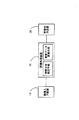
図1は、本発明の一実施形態にかかる画像処理システムをブロック図により示しており、図2は具体的ハードウェア構成例をブロック図により示している。
【0077】
同図において、画像入力装置10は画像を撮像するなどして画像データを画像処理装置20へ出力し、同画像処理装置20は所定のコントラスト強調などの画像処理を行なって画像出力装置30に出力し、同画像出力装置30はコントラストを強調された画像を表示する。
【0078】
ここにおいて、画像入力装置10の具体例はスキャナ11やデジタルスチルカメラ12あるいはビデオカメラ14などが該当し、画像処理装置20の具体例はコンピュータ21とハードディスク22などからなるコンピュータシステムが該当し、画像出力装置30の具体例はプリンタ31やディスプレイ32等が該当する。
【0079】
本画像処理システムにおいては、コントラストの弱い画像に対して最適なコントラストを与えようとしているものであるから、画像入力装置10としてのスキャナ11で写真を撮像した画像データであるとか、デジタルスチルカメラ12で撮影したコントラストの弱い画像データなどが処理の対象となり、画像処理装置20としてのコンピュータシステムに入力される。
【0080】
本画像処理装置20は、少なくとも、輝度の分布を抽出する輝度分布検出手段と、この検出された輝度分布に基づいて再現可能な範囲内での同輝度分布の拡大可能な程度を判別して画像データを変換する画像データ変換手段を構成する。むろん、本画像処理装置20は、この他にも機種毎による色の違いを補正する色変換手段であったり、機種毎に対応した解像度を変換する解像度変換手段などを構成していても構わない。この例では、コンピュータ21はRAMなどを使用しながら、内部のROMやハードディスク22に保存されている各画像処理のプログラムを実行していく。なお、このような画像処理のプログラムは、CD−ROM、フロッピーディスク、MOなどの各種の記録媒体を介して供給される他、モデムなどによって公衆通信回線を介して外部のネットワークに接続し、ソフトウェアやデータをダウンロードして導入することも行われている。
【0081】
この画像処理のプログラムの実行結果は後述するようにコントラストを強調した画像データとして得られ、得られた画像データに基づいて画像出力装置30であるプリンタ31で印刷したり、同じ画像出力装置30であるディスプレイ32に表示する。なお、この画像データは、より具体的にはRGB(緑、青、赤)の階調データとなっており、また、画像は縦方向(height)と横方向(wideth)に格子状に並ぶドットマトリクスデータとして構成されている。すなわち、当該画像データは画像をドットマトリクス状の画素に分解して各画素の情報を表したものとなっている。
【0082】
本実施形態においては、画像の入出力装置の間にコンピュータシステムを組み込んで画像処理を行うようにしているが、必ずしもかかるコンピュータシステムを必要とする訳ではなく、図3に示すようにデジタルスチルカメラ12a内にコントラストを強調する意味での画像処理装置を組み込み、変換した画像データを用いてディスプレイ32aに表示させたりプリンタ31aに印字させるようなシステムであっても良い。また、図4に示すように、コンピュータシステムを介することなく画像データを入力して印刷するプリンタ31bにおいては、スキャナ11bやデジタルスチルカメラ12bあるいはモデム13b等を介して入力される画像データを自動的にコントラスト強調するように構成することも可能である。
【0083】
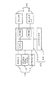
コンピュータ21にて実行する画像処理の内、輝度分布検出手段に相当する輝度の分布検出処理と画像データ変換手段に相当する輝度変換処理とをそれぞれ図5及び図6に示している。
【0084】
図5は主に輝度の分布検出処理に該当しており、まず、この輝度の分布検出処理について説明する。
【0085】
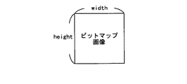
輝度をいかにして表すかについて説明する前に、分布対象となる画素について説明する。図5のステップS102で示すように対象となる画素を間引く間引き処理を実行する。図7に示すように、ビットマップの画像であれば、縦方向に所定ドットと横方向に所定ドットからなる二次元のドットマトリクスとして成り立っており、正確な輝度の分布を求めるのであれば全画素について輝度を調べる必要がある。しかしながら、この分布抽出処理は分布の幅を求めることを目的としており、必ずしも正確である必要はない。従って、ある誤差の範囲内となる程度に間引きを行うことが可能である。統計的誤差によれば、サンプル数Nに対する誤差は概ね1/(N**(1/2))と表せる。ただし、**は累乗を表している。従って、1%程度の誤差で処理を行うためにはN=10000となる。
【0086】
ここにおいて、図7に示すビットマップ画面は(width)×(height)の画素数となり、サンプリング周期ratioは、
ratio=min(width,height)/A+1 …(5)
とする。ここにおいて、min(width,height)はwidthとheightのいずれか小さい方であり、Aは定数とする。また、ここでいうサンプリング周期ratioは何画素ごとにサンプリングするかを表しており、図8の○印の画素はサンプリング周期ratio=2の場合を示している。すなわち、縦方向及び横方向に二画素ごとに一画素のサンプリングであり、一画素おきにサンプリングしている。A=200としたときの1ライン中のサンプリング画素数は図9に示すようになる。
【0087】
同図から明らかなように、サンプリングしないことになるサンプリング周期ratio=1の場合を除いて、200画素以上の幅があるときには最低でもサンプル数は100画素以上となることが分かる。従って、縦方向と横方向について200画素以上の場合には(100画素)×(100画素)=(10000画素)が確保され、誤差を1%以下にできる。
【0088】
ここにおいてmin(width,height)を基準としているのは次のような理由による。例えば、図10(a)に示すビットマップ画像のように、width>>heightであるとすると、長い方のwidthでサンプリング周期ratioを決めてしまった場合には、同図(b)に示すように、縦方向には上端と下端の2ラインしか画素を抽出されないといったことが起こりかねない。しかしながら、min(width,height)として、小さい方に基づいてサンプリング周期ratioを決めるようにすれば同図(c)に示すように少ない方の縦方向においても中間部を含むような間引きを行うことができるようになる。
【0089】
なお、この例では、縦方向と横方向の画素について正確なサンプリング周期で間引きを行うようにしている。これは、逐次入力される画素について間引きしながら処理する場合に好適である。しかし、全画素が入力されている場合には縦方向や横方向についてランダムに座標を指定して画素を選択するようにしても良い。このようにすれば、10000画素というような必要最低限の画素数が決まっている場合に10000画素となるまでランダムに抽出する処理を繰り返し、10000画素となった時点で抽出を止めればよくなる。
【0090】
このように選択した画素についての画素データがその成分要素として輝度を持っていればその輝度値を用いて分布を求めることが可能である。しかしながら、輝度値が直接の成分値となっていない画像データの場合でも、間接的には輝度を表す成分値を備えている。従って、輝度値が直接の成分値となっていない表色空間から輝度値が直接の成分値となっている表色空間への変換を行えば輝度値を得ることができる。
【0091】
このような異なる表色空間の間での色変換は変換式によって一義的に定まるものではなく、それぞれの成分値を座標とする色空間について相互に対応関係を求めておき、この対応関係を記憶した色変換テーブルを参照して逐次変換する必要がある。テーブルとする関係上、成分値は階調値として表され、三次元の座標軸を備えている256階調の場合には、約1670万個(256×256×256)の要素の色変換テーブルを持たなければならない。効率的な記憶資源の利用を考えた結果、すべての座標値についての対応関係を用意しておくのではなく、通常は適当なとびとびの格子点について対応関係を用意しておき、補間演算を併用するようにしている。この補間演算はいくつかの乗算や加算を経て可能となるものであるため、演算処理量は膨大となってくる。
【0092】
すなわち、フルサイズの色変換テーブルを使用するのであれば処理量としては少なくなるもののテーブルサイズが非現実的となり、テーブルサイズを現実的なサイズにすれば演算処理量が非現実的となることが多い。
【0093】
このような状況に鑑み、本実施形態においては、テレビジョンなどの場合に利用されているように、RGBの三原色から輝度を求める次式の変換式を採用している。すなわち、P点での輝度yp についてはRGBの成分値(Rp,Gp,Bp )から、
yp=0.30Rp+0.59Gp+0.11Bp …(6)
とする。このようにすれば、三回の乗算と二回の加算だけで輝度値を求めることができるようになる。
【0094】
本実施形態においては、RGBの表色空間を対象としている結果、このような変換式を採用しているが、その背景には各成分値が色の明るさを示しているので、それぞれの成分値を単独で見た場合に輝度に線形に対応しているという性質がある。従って、よりおおざっぱに言えばそれぞれの加算割合を考慮することなく単に
yp=(Rp+Gp+Bp)/3 …(7)
というように簡略化することも不可能ではないし、さらには、
yp=Gp …(7)’
というように、(6)式においても最も割合の大きい緑の成分値を輝度値としてしまうことも可能である。
【0095】
間引き処理では、選択した画素についてRGBの画像データから同時に輝度を求めて分布をとる。最終的にはステップS116にてこの分布の幅を求めることになるが、その前に考慮しておく事項がある。
【0096】
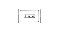
一つ目は画像が白黒画像のような二値画像である場合である。白黒画像を含めて二値画像であればコントラストの強調という概念は不適切である。図11に示すような白黒画像があったとすると、この画像に対する輝度分布は図12に示すように再現可能な範囲における両端に集中する。それも、基本的には階調「0」と階調「255」に集中する。
【0097】
従って、ステップS104で白黒チェックを行う場合には、階調「0」と階調「255」の画素数の和が、間引いて選択した画素数と一致するか否かで判断できる。そして、白黒画像の場合であれば以下の処理を実行することなく処理を中断するためにステップS106にて非拡大処理を実行する。本実施形態においては分布抽出処理と輝度変換処理とを大きく分けているので、この非拡大処理では後段の輝度変換処理も実行しないようなフラグを立てて当該分布抽出処理を終了している。
【0098】
二値データは白黒だけに限らず、色の付いた二値データもあり得る。このような場合も同様にコントラストの強調を図る処理は不要であり、分布状態を調べて二つの値(一方は概ね「0」)にしか分布が集中していなければ二値データとして処理の中断を図ればよい。
【0099】
二つ目は画像がビジネスグラフのようなものか写真のような自然画であるか否かを考慮する。自然画においてはコントラストの強調という処理が要求される場合があるものの、ビジネスグラフであるとか絵画のようなものではコントラストの強調を図らない方が好まれる場合が多い。従って、ステップS108では自然画か否かのチェックを行う。
【0100】
自然画では陰影を含めて色数が極めて多いがビジネスグラフやある種の絵画では色数が限られていることが多い。従って、色数が少なければ自然画ではないと判断することが可能である。色数を正確に判断しようとすれば上述したように1670万色のうちの何色を使用しているかを判別する必要があるが、現実的ではない。一方、ビジネスグラフのような極めて色数が少ない場合には異なる色であって同じ輝度になる確率は低い。すなわち、輝度によって概ねの色数を判断できる。色数が少なければ輝度の分布もまばらであり、ビジネスグラフのようなものでは線スペクトル状に表れる。このようなことから、ステップS108では256階調の輝度のうち分布数が「0」でない輝度値がいくつ表れているかカウントする。そして、概ね一割となる「25」以下であれば自然画でないと判断し、二値データの場合と同様、ステップS106にて非拡大処理を実行する。むろん、しきい値となる「25」色以下か否かについては適宜変更可能である。
【0101】
また、分布が線スペクトル状か否かは分布数が「0」でない輝度値の隣接割合で判断することも可能である。すなわち、分布数が「0」でない輝度値であって隣接する輝度値に分布数があるか否かを判断する。隣接する二つの輝度値のうち少なくとも一方で隣接していれば何もせず、両方で隣接していない場合にカウントを行い、その結果、「0」でない輝度値の数とカウント値との割合で判断すればよい。例えば、「0」でない輝度値の数が「20」であって、隣接しないものの数が「20」であれば線スペクトル状に分布していることが分かる。
【0102】
さらに、オペレーティングシステムを介して画像処理プログラムが実行されているような場合には、画像ファイルの拡張子で判断することも可能である。ビットマップファイルのうち、特に写真画像などではファイル圧縮がなされ、その圧縮方法を表すために暗示の拡張子が利用されることが多い。例えば、「JPG」という拡張子であれば、JPEGフォーマットで圧縮されていることが分かる。オペレーティングシステムがファイル名を管理していることから、プリンタドライバなどの側からオペレーティングシステムに問い合わせを出せば、同ファイルの拡張子が回答されることになるため、その拡張子に基づいて自然画であると判断してコントラストの強調を行うようにすればよい。また、「XLS」というようなビジネスグラフに特有の拡張子であればコントラストの強調を行わないと判断することもできる。
【0103】
三つ目に考慮することは、図13に示すように画像の周りに枠部があるか否かである。このような枠部が白色または黒色であれば、その輝度分布は図14に示すように、その影響が再現可能な範囲における両端に線スペクトル状に表れるとともに、内部の自然画に対応して両端以外の内側に滑らかな輝度分布としても表れる。
【0104】
むろん、枠部を輝度分布の考慮に入れない方が適切であるため、ステップS108の枠部のチェックでは階調「0」と階調「255」の画素数の和が十分に大きく、かつ、間引いて選択した画素数とは一致しないかを判断し、肯定的ならば枠部があると判定してステップS112にて枠処理を実施する。この枠処理では、枠部を無視するために輝度分布のうち階調「0」と階調「255」の画素数を「0」にセットする。これにより、以下の処理では枠部がないものと同様に扱うことができる。
【0105】
この例では白色または黒色の枠部を対象としているが、特定の色の枠がある場合も考えられる。このような場合、輝度分布が描く本来の滑らかなカーブの中で突出する線スペクトル状のものが表れる。従って、隣接する輝度値の間で大きく差が生じている線スペクトル状のものについては枠部として考えて輝度分布の対象としないようにすればよい。この場合、枠部以外でその色を使用していることがあり得るので、両隣の輝度値の平均を割り当てるようにしても良い。
【0106】
以上のような考慮を経た上で、輝度分布の拡大を行う場合にはステップS116で輝度分布の両端を求める。自然画における輝度分布は図15に示すように概ね山形に表れる。むろん、その位置、形状についてはさまざまである。輝度分布の幅はこの両端をどこに決めるかによって決定されるが、単に裾野が延びて分布数が「0」となる点を両端とすることはできない。裾野部分では分布数が「0」付近で変移する場合があるし、統計的に見れば限りなく「0」に近づきながら推移していくからである。
【0107】
このため、分布範囲において最も輝度の大きい側と小さい側からある分布割合だけ内側に経た部分を分布の両端とする。本実施形態においては、図15に示すように、この分布割合を0.5%に設定している。むろん、この割合については、適宜、変更することが可能である。このように、ある分布割合だけ上端と下端をカットすることにより、ノイズなどに起因して生じている白点や黒点を無視することもできる。すなわち、このような処理をしなければ一点でも白点や黒点があればそれが輝度分布の両端となってしまうので、多くの場合において最下端は階調「0」であるし、最上端は階調「255」となってしまうが、上端部分から0.5%の画素数だけ内側に入った部分を端部とすることにより、このようなことが無くなる。
【0108】
実際の処理では処理対象となる画素数(間引き処理において選択した画素の総数、あるいは枠部に対応する画素数を削除した総数)に対する0.5%を演算し、再現可能な輝度分布における上端の輝度値及び下端の輝度値から順番に内側に向かいながらそれぞれの分布数を累積し、0.5%の値となった輝度値を求める。以後、この上端側をymaxと呼び、下端側をyminと呼ぶ。
【0109】
本実施形態においては、輝度分布に対してこのような処理を経て上端と下端とを求めているが、統計的処理のもとで両端を求めることも可能である。例えば、輝度値の平均値に対して何%以下となったところを端部とするといった手法を採用することも可能である。
【0110】
以上の処理が分布検出処理に該当し、次に、このようにして求めた輝度値ymax,yminに基づいて画像データの変換を行なう輝度変換処理について説明する。なお、上述したようにステップS106にて非拡大処理を実行した場合には、ステップS202にて所定のフラグを参照してそれを検知し、以下の処理を行うことなく当該画像処理を終了する。
【0111】
輝度の基本的な変換は、再現可能な輝度の範囲を「0」〜「255」としたときに、変換前の輝度yと輝度の分布範囲の最大値ymax と最小値ymin から変換先の輝度Yを次式に基づいて求める。
【0112】
Y=ay+b …(2)
ただし
a=255/(ymax−ymin) …(3)’
b=−a・ymin …(4)’
また、上記変換式にてY<0ならばY=0とし、Y>255ならばY=255とする。ここにおける、aは傾きであり、bはオフセットといえる。この変換式によれば、図16に示すように、あるせまい幅を持った輝度分布を再現可能な範囲まで広げることができる。なお、基本的に輝度の分布範囲の拡大においては、画素数が変化するわけではないので、ヒストグラムの面積は一致する。
【0113】
ところで、このように再現可能な範囲を最大限に利用して輝度分布の拡大を図った場合、ハイライト部分が白く抜けてしまったり、ハイシャドウ部分が黒くつぶれてしまうことが起こる。これを防止するため本実施形態においては、再現可能な範囲を制限している。すなわち、再現可能な範囲の上端と下端に拡大しない範囲として輝度値で「5」だけ残している。この結果、変換式のパラメータは次式のようになる。
【0114】
a=245/(ymax−ymin) …(8)
b=5−a・ymin …(9)
そして、この場合にはy<yminと、y>ymaxの範囲においては変換を行わないようにする。
【0115】
なお、本実施形態においては、ハイライト部分とハイシャドウ部分とを保持するために一律に端部から輝度値にして「5」の範囲を非拡大領域としているが、ハイライト部分やハイシャドウ部分を比較的再現しやすいような画像出力装置であればその範囲を狭くしても良いし、再現力がさらに弱い場合にはより範囲を大きくするようにしても良い。また、一律に拡大しないのではなく、ボーダー領域で徐々に拡大率を制限するようにしていっても良い。
【0116】
また、図17(a)には画像の輝度分布が狭い場合を示しているが、これまで述べたようにして輝度分布の拡大率(aに対応)を適用してしまうと、再現可能な範囲に合わせて非常に大きな拡大率が得られる場合も生じてくる。すると、夕方のような薄暮の状態では最も明るい部分から暗い部分までのコントラストの幅が狭くて当然であるのに、この画像についてコントラストを大きく拡大しようとする結果、昼間の画像のように変換されてしまいかねない。このような変換は希望されないので、拡大率には制限を設けておき、aが1.5(〜2)以上とはならないように制限する。これにより、薄暮は薄暮なりに表現されるようになる。
【0117】
拡大率に制限を設けない場合を図17(a)の一点鎖線に示しており、変換後には再現可能な範囲で余分な部分は残っていない。しかしながら、拡大範囲を制限する場合には、同図(b)の二点鎖線で示すように、変換後の分布をどこに持ってくるかの自由度が生じてしまい、場合によっては全体的に明るくなりすぎたり、暗くなり過ぎたりしかねない。
【0118】
このため、本実施形態においては、変換前における輝度分布が再現可能な範囲内において上端側と下端側に残っている残余の領域の割合(m1:m2)が、変換後において上端側と下端側に残っている残余の領域の割合(n1:n2)と一致するように変換する。以下、このようにする場合のパラメータbの求め方について説明する。
【0119】
変換前の画像の輝度分布において、
m1=ymin
m2=255−ymax
ここで、
m1+m2=255−(ymax−ymin)
従って、ydif=ymax−yminとすると、
m1+m2=255−ydif
変換後の画像の輝度分布において、
n1=Ymin
n2=255−Ymax
同様に、

【0120】
m1:m2=n1:n2であるから、
n1=m1(n1+n2)/(m1+m2)
=ymin(255−a・ydif)/(255−ydif)
一方、Y=ay+bであるから、b=Y−ayとなり、よって、
b=Ymin−a・ymin
=ymin{(255−a・ydif)/(255−ydif)−a} …(10)
となる。また、Ymax を用いて求めると、
b=Ymax−a・ymax
=255−(255−ymax)(255−a・ydif)/(255−ydif)−a・ymax …(11)
以上のようにしてパラメータbを得ることができ、ステップS204を終了する。
【0121】
ところで、輝度の変換時に、毎回、上記変換式(Y=ay+b)を実行するのは非合理的である。というのは、輝度yの取りうる範囲が「0」〜「255」でしかあり得ないため、予め輝度yが取りうる全ての値に対応して変換後の輝度Yを求めておくことも可能である。従って、ステップS206にてこの対応関係を求め、図18に示すようなテーブルとして記憶しておく。
【0122】
このような変換テーブルが形成されたところで画像データを変更することが可能になる。しかし、このような輝度の範囲の拡大によってコントラストを強調するだけでなく、合わせて明るさを調整することも極めて有効である。例えば、図19にて実線で示すように輝度分布の山が全体的に暗い側に寄っている場合には鎖線で示すように全体的に明るい側に山を移動させると良いし、逆に、図20にて実線で示すように輝度分布の山が全体的に明るい側に寄っている場合には鎖線で示すように全体的に暗い側に山を移動させると良い。
【0123】
各種の実験を行った結果、本実施形態においては、輝度分布におけるメジアンymedを求め、同メジアンymedが「85」未満である場合に暗い画像と判断して以下のγ値に対応するγ補正で明るくする。
【0124】
γ=ymed/85 …(12)
あるいは、
γ=(ymed/85)**(1/2) …(13)
とする。
【0125】
この場合、γ<0.7となっても、γ=0.7とする。このような限界を設けておかないと夜の画像が昼間のようになってしまうからである。なお、明るくしすぎると全体的に白っぽい画像になってコントラストが弱い画像になりやすいため、彩度を合わせて強調するなどの処理が好適である。
【0126】
一方、メジアンymedが「128」より大きい場合に明るい画像と判断して以下のγ値に対応するγ補正で暗くする。
【0127】
γ=ymed/128 …(14)
あるいは、
γ=(ymed/128)**(1/2) …(15)
とする。この場合、γ>1.3となっても、γ=1.3として暗くなり過ぎないように限界を設けておく。なお、暗くしすぎると色が乗りすぎて濃い画像になるので、合わせて彩度強調を弱くするなどの処理が好適である。ただし、明るい背景の中の被写体に対してはこのような暗くする処理はかえって悪影響を及ぼす場合もある。例えば、空が画像の半分をしめるような風景画像や晴れた日の記念写真などでは、ただでさえ逆光で顔が暗くつぶれ気味であることが多いからである。これらの画像の場合は暗い部分と明るい部分とが混じっているので輝度の標準偏差ystdを求めると比較的高い値となっていることが多い。従って、輝度の標準偏差ystd>70の場合には暗くするためのγ補正を行わないようにする。
【0128】
なお、このγ補正は変換前の輝度分布に対して行っても良いし、変換後の輝度分布に対して行っても良い。γ補正をした場合における対応関係を図21に示しており、γ<1であれば上方に膨らむカーブとなり、γ>1であれば下方に膨らむカーブとなる。むろん、かかるγ補正の結果も図18に示すテーブル内に反映させておけばよく、ステップS208にてテーブルデータに対して同補正を行っておく。
【0129】
最後に、ステップS210にて画像データの変換を行う。ここまでは輝度を変換するための対応関係を求めてきており、例えば、RGB座標軸における成分値(Rp,Gp,Bp )についての変換関係ではなかった。しかしながら、(2)式の変換式は、このRGBの成分値(Rp,Gp,Bp )との対応関係においても当てはめることができる。すなわち、変換前の成分値(r,g,b)に対して変換後の成分値(R,G,B)は、
R=a・r+b …(16)
G=a・g+b …(17)
B=a・b+b …(18)
として求めることもできる。これは(2)式と(4)式とがともに線形の対応関係を示していることから明らかである。また、輝度y,Yが階調「0」〜階調「255」であるのに対応してRGBの各成分値(r,g,b),(R,G,B )も同じ範囲となっており、上述した輝度y,Yの変換テーブルをそのまま利用すればよいといえる。
【0130】
従って、ステップS210では全画素の画像データ(r,g,b)について(16)〜(18)式に対応する変換テーブルを参照し、変換後の画像データ(R,G,B )を得るという処理を繰り返すことになる。
【0131】
次に、上記構成からなる本実施形態の動作を順を追って説明する。
【0132】
スキャナ11などで写真を撮像したとすると、同写真をRGBの階調データで表した画像データがコンピュータ21に取り込まれ、CPUは図5及び図6に示す画像処理のプログラムを実行して画像データのコントラストを強調する処理を実行する。
【0133】
まず、ステップS102では画像データを所定の誤差内となる範囲で間引き、選択した画素についての輝度yを求めて分布を取る。このままの分布を使用することはできず、まず、画像が白黒のような二値画像でないかステップS104にて判断するとともに、ステップS108では自然画か否かを判断する。二値画像である場合や自然画でない場合などを除き、ステップS110では画像データに枠部がないか判断し、枠部があれば除いて得られた輝度分布について上端と下端の0.5%の範囲を除去して分布の両端ymax ,ymin を取得する。
【0134】
輝度分布の両端ymax ,ymin が得られたら、
Y=ay+b …(2)
a=245/(ymax−ymin) …(8)
bについては、以下のいずれか
b=5−a・ymin …(9)
b=ymin{(255−a・ydif)/(255−ydif)−a} …(10)
b=255−(255−ymax)(255−a・ydif)/(255−ydif)−a・ymax …(11)
なる関係式より、ステップS204にてパラメータa,bを求めるとともに、ステップS206では輝度yから輝度Yへの変換関係をテーブルに記憶する。ステップS208では必要に応じてγ補正を実行し、完成した変換テーブルを参照してステップS210では全画素についての画像データを変換する。
【0135】
むろん、上述したように二値画像や自然画でない場合においてはかかる画像処理は行われないが、本発明の画像処理が行われた場合には、写真の状態では非常にコントラストが弱かったにもかかわらず、輝度の範囲を広げるように補正することにより、明暗がはっきりして鮮明な画像を得られるようになる。
【0136】
なお、上述した実施形態においては、拡大率の制限などを一定としているが、コンピュータ21上では所定のGUIを介してユーザーが選択できるようにしても良い。また、ユーザーが画像データの一部を指定して当該範囲内でのみかかるコントラストの強調処理を実行するようにすることも可能である。
【0137】
このように、ステップS102で間引きするなどしながら画像データの画素について輝度yを求めた後、上端と下端において所定の分布割合だけ内側に入った端部を当該輝度分布の端部をみなすことにより(ステップS116)、輝度の再現可能な範囲内での拡大率に対応するパラメータaと、オフセット量に対応するパラメータbとを得ることができるようになるため、変換元の輝度yに対して変換先輝度YをY=ay+bなる関係式などを利用して自動的に変換可能となる。
【0138】
なお、ビデオカメラ14の入力画像については、演算速度が間に合わないこともあり得る。従って、そのような場合には撮影のシーンごとに輝度の検出を行って輝度の分布を検知し、そのシーンにおいては同様の傾向であるものと想定して輝度の拡大テーブルを作成しておくとともに、フレームごとに同拡大テーブルに対応して輝度分布を拡大するようにすればよい。むろん、十分な演算速度があれば各フレームごとに変換するようにしても良い。むろん、同様の変換は受像機の側で行うことも可能である。
【図面の簡単な説明】
【図1】本発明の一実施形態にかかる画像処理装置が適用される画像処理システムのブロック図である。
【図2】同画像処理装置の具体的ハードウェア構成例を示すブロック図である。
【図3】本発明の画像処理装置の他の適用例を示す概略ブロック図である。
【図4】本発明の画像処理装置の他の適用例を示す概略ブロック図である。
【図5】本発明の画像処理装置における輝度の分布抽出処理部分を示すフローチャートである。
【図6】本発明の画像処理装置における輝度変換処理部分を示すフローチャートである。
【図7】変換元の画像における座標を示す図である。
【図8】サンプリング周期を示す図である。
【図9】サンプリング画素数を示す図である。
【図10】変換元の画像とサンプリングされる画素の関係を示す図である。
【図11】白黒の画像を示す図である。
【図12】白黒の画像の輝度分布を示す図である。
【図13】枠部のある画像を示す図である。
【図14】枠部のある画像の輝度分布を示す図である。
【図15】輝度分布の端部処理と端部処理にて得られる端部を示す図である。
【図16】輝度分布の拡大と再現可能な範囲を輝度の範囲を示す図である。
【図17】輝度分布の拡大率に制限を与える場合を示す図である。
【図18】輝度分布を拡大する際の変換テーブルを示す図である。
【図19】γ補正で明るくする概念を示す図である。
【図20】γ補正で暗くする概念を示す図である。
【図21】γ補正で変更される輝度の対応関係を示す図である。
【符号の説明】
10…画像入力装置
11…スキャナ
11b…スキャナ
12…デジタルスチルカメラ
12a…デジタルスチルカメラ
12b…デジタルスチルカメラ
13b…モデム
20…画像処理装置
21…コンピュータ
22…ハードディスク
30…画像出力装置
31…プリンタ
31a…プリンタ
31b…プリンタ
32…ディスプレイ
32a…ディスプレイ[0001]
BACKGROUND OF THE INVENTION
The present invention relates to an image processing apparatus, an image processing method, and a medium on which an image processing program is recorded, and more particularly to an image processing apparatus, an image processing method, and a medium on which an image processing program is recorded.
[0002]
[Prior art]
Conventionally, as this type of image processing apparatus, an apparatus disclosed in Japanese Patent Publication No. 7-66318 is known.
[0003]
In the image processing apparatus shown in the same publication, the relationship between the luminance y ′ after conversion and the luminance y ′ after conversion as shown in equation (1), and the image is based on the parameter a or parameter b selected by the operator. The brightness of the data is converted. As a result, an image in which the contrast is enhanced for image data having a low contrast is obtained.
[0004]
y ′ = ay + b (1)
[0005]
[Problems to be solved by the invention]
In the above-described conventional image processing apparatus, a plurality of settings with different levels of contrast strength are prepared in advance and switched. Therefore, the most suitable one corresponding to actual image data cannot be automatically applied. In particular, in the case of changing based on the expression (1), if the whole image is bright, only the brightness is emphasized. If the whole image is dark, the darkness is only emphasized. Sometimes.
[0006]
Further, although the contrast strength can be operated on a television or the like, it has not been possible to automate the execution of optimum enhancement on each image.
[0007]
SUMMARY An advantage of some aspects of the invention is that it provides an image processing apparatus capable of automatically adjusting contrast, an image processing method, and a medium on which an image processing program is recorded.
[0008]
[Means for Solving the Problems]
In order to achieve the above object, an image processing apparatus that performs predetermined image processing on image data of an image composed of a plurality of pixels, totals the luminance distribution based on the luminance at each pixel, and totals The luminance distribution of each pixel in the image data is widely dispersed in an effective luminance range that can be taken by the image data, with the luminance distribution in which the inner portion is regarded as an end portion by a predetermined distribution ratio from the actual edge portion in the obtained luminance distribution. It is good also as a structure which converts information.
[0009]
In the above configuration, the luminance distribution as a whole is totaled based on the luminance at each pixel, and the luminance distribution in which the inner portion is regarded as the end portion by a predetermined distribution ratio from the actual end portion in the totaled luminance distribution is the image. The luminance information of each pixel in the image data is converted so as to be widely distributed in an effective luminance range that the data can take. That is, when the image data represents the information of each pixel by decomposing the image into dot matrix pixels, the brightness distribution in the image data is obtained, so that the width of the contrast in the image data is to some extent The distribution can be quantified, and the distribution can be expanded corresponding to the reproducible range.
[0010]
Needless to say, the numerical value is not necessarily a specific numerical value, and may be handled as a numerical value in the process, or may be handled as a signal magnitude.
The invention according to
[0011]
In order to obtain the luminance distribution in handling the image data of the predetermined image, the luminance distribution detecting means adds up the luminance distribution as a whole based on the luminance at each pixel, and determines the predetermined luminance from the actual end of the tabulated luminance distribution. A luminance distribution in which the inner portion is regarded as an end portion by the distribution ratio is detected. Then, using the detected luminance distribution, the image data conversion means detects an enlargement ratio for expanding the luminance distribution in an effective luminance range that can be taken by the image data, and uses the enlargement ratio to detect the image data. The luminance information of each pixel is converted.
[0012]
That is, the so-called contrast width from the brightest brightness to the darkest brightness can be determined by obtaining the brightness distribution of the image data in pixel units, and the contrast magnification can be determined by comparing with the reproducible brightness width range. Therefore, after that, it is sufficient to enlarge the luminance distribution so that the enlargement ratio is obtained. For example, after the luminance distribution as a whole is aggregated based on the luminance at each pixel, the luminance distribution is the same when the aggregated luminance distribution is not widely dispersed in the effective luminance range that the image data can take. The luminance information of each pixel in the image data is converted so as to be widely distributed in the luminance range.
[0013]
Any number of methods are possible for enlarging the luminance distribution, and the luminance distribution of the image data may be enlarged within a possible range. To explain the main point, the statistical width of the detected luminance distribution is compared with the width of the reproducible luminance range to obtain the degree of enlargement as the enlargement ratio, and the upper and lower ends of the enlarged luminance distribution. Is to obtain an adjustment value so as to be within the luminance range, and to individually correct the luminance of each pixel. As a specific example, the invention according to
[0014]
Y = ay + b (2)
However,
a = yrange / (ymax−ymin) (3)
b = −a · ymin (4)
In the above conversion equation, if Y <0, Y = 0, and if Y> yrange, Y = yrange.
[0015]
This conversion is so-called linear expansion, and although the conversion formula itself is the same as the conventional one, it is significant that the parameters are selected by the image data conversion means. Regardless of the selection of b, Y = 0 when y = ymin, and Y = yrange when y = ymax. Then, the luminance distribution is uniformly spread within a range of yrange which is a reproducible luminance range. In this example, it is a so-called narrow-sense linear transformation, and of course, it is not necessary to be limited to this, and a broad-sense nonlinear transformation can also be implemented. Further, it goes without saying that the conversion formula is merely an example and can be applied even if the conversion formula has the same meaning.
[0016]
Further, it may not be possible to deal with a case where the entire image is bright or dark just by increasing the contrast, and the image data conversion means obtains the maximum distribution luminance of the conversion source luminance y, and the maximum distribution luminance of the same. A configuration may be adopted in which the luminance Y of the conversion destination is obtained by γ correction based on the affiliation range.
[0017]
As a method for determining whether or not the image data is generally bright, the maximum distribution luminance of the conversion source luminance y is used, and if this maximum distribution luminance is on the bright side, the entire distribution is darkened by γ correction. If the brightness is on the dark side, the entire brightness is automatically corrected, which cannot be obtained only by contrast enhancement, by making the entire screen brighter by γ correction. Here, the maximum distribution luminance of the luminance y of the conversion source may be obtained by median or may be obtained by an average value.
[0018]
When converting the luminance by various methods, the invention according to
[0019]
Although it is not impossible to calculate the luminance every time based on the conversion formula, the range of values that the luminance distribution can take is determined. For this reason, if the conversion destination luminance Y is calculated and stored in advance based on the conversion source luminance y, it is possible to perform conversion only by invoking the correspondence at the time of conversion.
[0020]
In converting the luminance, the image data may be included as luminance data, or may be indirect only including luminance data. Of course, if direct luminance data is included, it may be converted, and even if it is indirect luminance data, it may be converted into luminance data before performing predetermined luminance conversion. However, the luminance conversion does not have to be very accurate, and it can be said that it is sufficient to know roughly.
[0021]
In that sense, since strict accuracy is not required, the invention according to claim 4 is the image processing apparatus according to any one of
[0022]
When the image data is represented by so-called RGB (red, green, and blue) gradation data, it can be said that each component value for red, green, and blue corresponds to the luminance. For this reason, it can be said that linear addition of the same component values sufficiently represents luminance, and can be an extremely easy conversion method.
[0023]
The luminance distribution as an image does not necessarily have to be obtained for all the pixels of the image data as the luminance for each pixel is obtained. For example, the luminance distribution is obtained by thinning out the image data corresponding to a predetermined extraction rate. It is good.
[0024]
For the purpose of obtaining the distribution, it is possible to obtain a luminance distribution with a certain degree of certainty according to the extraction rate even if thinning is performed at a predetermined extraction rate without obtaining luminance for all pixels.
[0025]
Here, although there are various thinning methods, a predetermined number of extractions may be secured on the short side in the vertical and horizontal ranges.
[0026]
Since the image is flat, the image data is also naturally distributed in the vertical and horizontal directions, but in determining a certain extraction rate, by ensuring a certain number of extractions at least on the short side, the extraction rate is reduced. The certainty corresponding to it is held.
[0027]
Furthermore, when obtaining the luminance distribution, a configuration may be adopted in which the inner portion is regarded as the end portion by a predetermined distribution ratio from the actual end portion.
[0028]
Considering the luminance distribution of the image data statistically, it is reasonable to consider that the distribution is up to both end portions within a reproducible luminance range although it is extremely small. Therefore, both ends of the actual luminance distribution are always at both ends in a reproducible luminance range. If these both ends are employed, the enlargement ratio is substantially “1”, and thus the original effect cannot be achieved.
[0029]
However, if the predetermined distribution ratios at both ends are excluded, the bottom portion having a very small distribution is statistically ignored and appropriately ignored. For this reason, this range is used as a reference for determining the degree of enlargement.
[0030]
The predetermined distribution ratio only needs to be capable of ignoring the bottom part with extremely small distribution, and may be a certain number of pixels of the total number of pixels, or the distribution is less than a certain number. Sometimes it can be considered as an end.
[0031]
Furthermore, the invention according to
[0032]
In an actual image, there are a highlight portion and a high shadow portion, and the human eye is likely to realize a subtle difference in these portions. Therefore, if the enlargement is applied to the end of the so-called reproducible luminance range, the highlight portion will appear white and the high shadow portion will appear black.
[0033]
However, by setting the range of the luminance distribution to be enlarged inward by a predetermined amount from the end part of the actual reproducible range, no intentional enlargement is performed at both end parts.
[0034]
Furthermore, in the invention according to
[0035]
It may be natural that the contrast is narrow. For example, in the evening scenery, it is natural that the width of the luminance distribution is narrow, and if it is enlarged more than necessary, it becomes a daytime scenery. A similar example is possible in other cases, and this phenomenon is avoided by setting a limit on the expansion range of the luminance distribution.
[0036]
Furthermore, a configuration in which the corresponding position of the luminance distribution range before conversion within the reproducible range and the corresponding position of the luminance distribution range after conversion may be held.
[0037]
If the luminance distribution is used as much as possible within a reproducible range, there is no remaining range in which the luminance distribution can be expanded. However, if the expansion range is limited, there remains a remaining range in which the luminance distribution can be expanded. In other words, there remains a degree of freedom in which range is enlarged around, and the atmosphere of the image may change depending on the center. Therefore, the corresponding position of the luminance distribution range before conversion within the reproducible range and the corresponding position of the luminance distribution range after conversion are held so that the center does not change.
[0038]
Various ways of capturing the center of the luminance distribution of the image in this sense are possible. The invention according to
[0039]
That is, since it is only necessary to hold the center substantially, it is not always necessary to directly hold and hold the same center, but conversely, the enlargement remaining at the upper and lower ends of the luminance distribution range before conversion A possible range is captured, and the luminance distribution is expanded so that the ratio of this range is maintained even after conversion, so that the center is substantially maintained.
[0040]
Further, the invention according to claim 6 is the image processing apparatus according to any one of
[0041]
Since it can be said that there is no substantial luminance distribution for the binary image, if the binary image data is determined from the luminance distribution, the luminance distribution is not expanded.
[0042]
Since the binary image data can also have a certain color, it can have two luminance levels corresponding to the presence or absence of the color. Although it is possible to determine whether or not the brightness of the color, if there is no information suggesting it, the invention according to claim 7 can be reproduced in the image processing apparatus according to claim 6. It is configured to determine that the binary image data is black and white when the luminance distribution is concentrated at both ends in the range.
[0043]
That is, for a black and white image, it can be determined that the luminance distribution is concentrated at both ends within the reproducible range.
[0044]
Further, the frame portion of the image data may be determined based on the protruding luminance distribution, and if there is a frame portion, the frame data may not be used for expanding the luminance distribution.
[0045]
When an image is processed, it can frequently occur that it has a frame. If it exists as a single-color frame, only the luminance distribution corresponding to that color naturally protrudes. Accordingly, if such a prominent luminance distribution is used as a criterion for the enlargement determination, an effective determination cannot be made. Therefore, it is determined that the frame portion is not used for expanding the luminance distribution.
[0046]
Furthermore, as an example, a configuration may be adopted in which the luminance distribution concentrated at the end within the reproducible range is determined to be the frame portion.
[0047]
A white frame or a black frame is frequently used and may be generated depending on a trimming result, and corresponds to an end portion within a reproducible range. Therefore, the luminance distribution concentrated on the end portion is determined as the frame portion.
[0048]
By the way, the invention according to claim 8 is configured such that in the image processing apparatus according to any one of
[0049]
The narrowness of contrast tends to be a problem for natural pictures such as photographs, and it can be said that it is almost unnecessary for things like business graphs. Conversely, modifying something like a business graph can lead to a difference from the creator's image. Therefore, the luminance distribution is expanded only in the case of such a natural image.
[0050]
As an example of determining whether or not the image is a natural image, the invention according to claim 9 is the image processing device according to claim 8, wherein the image data is determined not to be a natural image when the luminance distribution exists in a line spectrum shape. The natural image determining means is provided.
[0051]
It can be said that the brightness distribution has a smooth width as a feature of the natural image. Therefore, if the luminance distribution appears in a line spectrum, it can be determined that the image is not a natural image. In the invention according to claim 9 configured as described above, the natural image determination means determines the state of the luminance distribution, and determines that the image data is not a natural image when it exists in the form of a line spectrum. Will not be expanded.
[0052]
As described above, the method for converting the image data so as to expand the distribution corresponding to the reproducible range by obtaining the luminance distribution in the image data is not necessarily limited to a substantial apparatus. It can be easily understood that it also functions as a method. For this reason, the invention according to
[0053]
That is, it is not necessarily limited to a substantial apparatus, and there is no difference that the method is effective.
[0054]
By the way, such an image processing apparatus may exist alone, or may be used in a state of being incorporated in a certain device. The idea of the invention is not limited to this, and includes various aspects. . Therefore, it can be changed as appropriate, such as software or hardware.
[0055]
As an example, a printer driver that converts image data corresponding to printing ink based on input image data and prints it on a predetermined color printer supports a range that can be reproduced by obtaining a luminance distribution in the image data. Thus, the image data can be converted to expand the distribution.
[0056]
In other words, the printer driver converts the image data input corresponding to the printing ink. At this time, the brightness distribution of the input image data is obtained, and the distribution is expanded corresponding to the reproducible range. The input image is converted so as to obtain a distribution and printed.
[0057]
In the case of software for an image processing apparatus as an embodiment of the idea of the invention, it naturally exists on a recording medium on which such software is recorded and must be used. As an example, the invention according to claim 11 is a medium in which image data of an image composed of a plurality of pixels is input by a computer and an image processing program for performing predetermined image processing is recorded, and the luminance at each pixel A luminance distribution as a whole based on the luminance distribution, detecting a luminance distribution in which the inner portion is regarded as an end portion by a predetermined distribution ratio from an actual end portion in the totaled luminance distribution, and the detected luminance distribution Detecting within a predetermined limit an enlargement ratio that expands in an effective luminance range that can be taken by the image data, and using the enlargement ratio to convert luminance information of each pixel in the image data, The ratio of the remaining area remaining on the upper end side of the luminance distribution and the remaining area remaining on the lower end side within the effective luminance range within the effective luminance range before conversion is changed within the effective range. After the the ratio of the remaining area remaining in the residual area and the lower end side remaining at the upper end of the luminance distribution, it is constituted comprising a step of performing conversion to match.
[0058]
Of course, the recording medium may be a magnetic recording medium, a magneto-optical recording medium, or any software recording medium to be developed in the future. In addition, the duplication stages such as the primary duplication product and the secondary duplication product are equivalent without any question. In addition, even when the communication method is used as a supply method, the present invention is not changed, and the same applies to the case where data is written on a semiconductor chip.
[0059]
Further, even when a part is software and a part is realized by hardware, there is nothing completely different in the idea of the invention, and a part is stored on a recording medium, and it is appropriately changed as necessary. It may be in the form of being read. Furthermore, it goes without saying that the present invention can also be applied to an image processing apparatus built in a color facsimile machine, a color copier, a color scanner, a digital camera, a digital video, or the like.
[0060]
【The invention's effect】
As described above, according to the present invention, by obtaining the luminance distribution, it becomes possible to quantitatively handle the width of the contrast of the image, and the degree of enlargement within a reproducible range can be obtained. Therefore, an image processing apparatus capable of automating contrast enhancement can be provided.
[0061]
According to the invention of
[0062]
Furthermore, the degree of brightness that cannot be corrected only by contrast enhancement can be adjusted.
[0063]
Further, according to the invention of
[0064]
Furthermore, according to the fourth aspect of the present invention, the luminance can be easily obtained with a necessary and sufficient accuracy.
[0065]
Furthermore, the amount of processing can be reduced.
[0066]
Furthermore, the bias of the image extraction point is eliminated, and the luminance distribution is likely to be accurate.
[0067]
Furthermore, it is possible to obtain a luminance distribution that is more effective for judgment.
[0068]
Furthermore, according to the fifth aspect of the present invention, the highlight portion and the high shadow portion can be prevented from being crushed.
[0069]
Furthermore, according to the first aspect of the present invention, it is possible to prevent the contrast of the image from being changed too much by changing the atmosphere of the image.
[0070]
Furthermore, according to the first aspect, it is possible to maintain the atmosphere expressed by the brightness of the image, and to easily execute it.
[0071]
Furthermore, according to the invention according to claim 6, it is possible to easily determine an unnecessary condition for expansion of the luminance distribution so as not to perform the expansion, and further, according to the invention according to claim 7, It is possible to efficiently determine a monochrome image having a high frequency.
[0072]
Furthermore, it is possible to prevent the processing from being inaccurate due to the brightness of the frame portion that tends to appear in the image, and it is possible to easily determine a frequently-used black and white frame portion.
[0073]
Furthermore, according to the invention according to claim 8, it can be performed only in the case of a natural image that needs to be expanded in luminance distribution. Further, according to the invention according to claim 9, whether or not it is a natural image. Can be easily determined.
[0074]
According to the invention of
[0075]
DETAILED DESCRIPTION OF THE INVENTION
Hereinafter, embodiments of the present invention will be described with reference to the drawings.
[0076]
FIG. 1 is a block diagram illustrating an image processing system according to an embodiment of the present invention, and FIG. 2 is a block diagram illustrating a specific hardware configuration example.
[0077]
In the figure, an
[0078]
Here, a specific example of the
[0079]
In the present image processing system, since an optimum contrast is to be given to an image having a low contrast, it is image data obtained by taking a photograph with a scanner 11 as the
[0080]
The
[0081]
The execution result of this image processing program is obtained as image data with enhanced contrast as will be described later, and is printed by the printer 31 that is the
[0082]
In the present embodiment, a computer system is incorporated between image input / output devices to perform image processing. However, such a computer system is not necessarily required, and a digital still camera as shown in FIG. A system in which an image processing device for emphasizing contrast is incorporated in 12a and the converted image data is displayed on the
[0083]
Of the image processing executed by the computer 21, luminance distribution detection processing corresponding to luminance distribution detection means and luminance conversion processing corresponding to image data conversion means are shown in FIGS. 5 and 6, respectively.
[0084]
FIG. 5 mainly corresponds to luminance distribution detection processing. First, the luminance distribution detection processing will be described.
[0085]
Before describing how to represent luminance, the pixels to be distributed will be described. As shown in step S102 of FIG. 5, a thinning process for thinning out the target pixels is executed. As shown in FIG. 7, in the case of a bitmap image, it is formed as a two-dimensional dot matrix consisting of predetermined dots in the vertical direction and predetermined dots in the horizontal direction, and all pixels can be obtained if an accurate luminance distribution is obtained. It is necessary to examine the brightness. However, this distribution extraction process is intended to determine the width of the distribution and need not be accurate. Therefore, it is possible to perform thinning to such an extent that it is within a certain error range. According to the statistical error, the error with respect to the number of samples N can be expressed as 1 / (N ** (1/2)). However, ** represents a power. Therefore, in order to perform processing with an error of about 1%, N = 10000.
[0086]
Here, the bitmap screen shown in FIG. 7 has the number of pixels of (width) × (height), and the sampling period ratio is
ratio = min (width, height) / A + 1 (5)
And Here, min (width, height) is the smaller of width and height, and A is a constant. Further, the sampling period ratio here indicates how many pixels are sampled, and the pixels marked with ◯ in FIG. 8 indicate the case where the sampling period ratio = 2. That is, one pixel is sampled every two pixels in the vertical and horizontal directions, and every other pixel is sampled. The number of sampling pixels in one line when A = 200 is as shown in FIG.
[0087]
As can be seen from the figure, except for the case where the sampling period ratio = 1 in which sampling is not performed, when there is a width of 200 pixels or more, the number of samples is at least 100 pixels. Therefore, in the case of 200 pixels or more in the vertical direction and the horizontal direction, (100 pixels) × (100 pixels) = (10000 pixels) is secured, and the error can be reduced to 1% or less.
[0088]
Here, the reason for using min (width, height) as a reference is as follows. For example, as shown in FIG. 10 (a), when width >> height is satisfied and the sampling period ratio is determined by the longer width, as shown in FIG. 10 (b). In addition, in the vertical direction, only two lines of the upper end and the lower end may be extracted. However, if the sampling period ratio is determined based on the smaller one as min (width, height), thinning is performed so as to include the intermediate portion in the smaller vertical direction as shown in FIG. Will be able to.
[0089]
In this example, thinning is performed with an accurate sampling period for pixels in the vertical and horizontal directions. This is suitable for processing while thinning out pixels that are sequentially input. However, when all the pixels have been input, the pixels may be selected by randomly specifying coordinates in the vertical direction or the horizontal direction. In this way, when the necessary minimum number of pixels, such as 10,000 pixels, is determined, the extraction process is repeated at random until the number of pixels reaches 10,000, and the extraction is stopped when the number of pixels reaches 10,000.
[0090]
If the pixel data for the selected pixel has luminance as its component element, the distribution can be obtained using the luminance value. However, even in the case of image data in which the luminance value is not a direct component value, the component value that indirectly represents the luminance is provided. Accordingly, the luminance value can be obtained by performing conversion from the color space where the luminance value is not a direct component value to the color space where the luminance value is a direct component value.
[0091]
Such color conversion between different color spaces is not uniquely determined by a conversion formula, but a mutual relationship is obtained for each color space having the respective component values as coordinates, and this correspondence is stored. It is necessary to perform sequential conversion with reference to the color conversion table. In relation to the table, the component value is expressed as a gradation value, and in the case of 256 gradations having a three-dimensional coordinate axis, a color conversion table of about 16.7 million (256 × 256 × 256) elements is obtained. Must have. As a result of considering the efficient use of storage resources, correspondence is not prepared for all coordinate values, but usually correspondence is prepared for appropriate discrete lattice points, and interpolation is used together. Like to do. Since this interpolation calculation is possible through several multiplications and additions, the amount of calculation processing becomes enormous.
[0092]
In other words, if a full-size color conversion table is used, the processing amount is reduced, but the table size becomes unrealistic. If the table size is made realistic, the calculation processing amount becomes unrealistic. Many.
[0093]
In view of such a situation, in the present embodiment, as used in the case of a television or the like, the following conversion formula for obtaining luminance from the three primary colors of RGB is adopted. That is, for the luminance yp at the point P, from the RGB component values (Rp, Gp, Bp),
yp = 0.30Rp + 0.59Gp + 0.11Bp (6)
And In this way, the luminance value can be obtained by only three multiplications and two additions.
[0094]
In this embodiment, as a result of targeting the RGB color space, such a conversion formula is adopted, but since each component value indicates the brightness of the color in the background, each component is When the value is viewed alone, it has a property of linearly corresponding to the luminance. Therefore, more roughly speaking, without considering each addition ratio simply
yp = (Rp + Gp + Bp) / 3 (7)
It is not impossible to simplify it, and
yp = Gp (7) '
In this way, it is also possible to use the green component value having the largest proportion in the formula (6) as the luminance value.
[0095]
In the thinning-out process, the luminance is obtained from the RGB image data at the same time for the selected pixel, and the distribution is obtained. Eventually, the width of this distribution is obtained in step S116, but there are matters to consider before that.
[0096]
The first is a case where the image is a binary image such as a black and white image. The concept of contrast enhancement is inappropriate for binary images including black and white images. If there is a black and white image as shown in FIG. 11, the luminance distribution for this image is concentrated at both ends in the reproducible range as shown in FIG. Basically, it concentrates on the gradation “0” and the gradation “255”.
[0097]
Therefore, when performing the black and white check in step S104, it can be determined whether or not the sum of the number of pixels of gradation “0” and gradation “255” matches the number of pixels selected by thinning. In the case of a monochrome image, the non-enlargement process is executed in step S106 in order to interrupt the process without executing the following process. In the present embodiment, the distribution extraction process and the luminance conversion process are roughly divided. Therefore, in this non-enlarging process, a flag is set so that the subsequent luminance conversion process is not executed, and the distribution extraction process is terminated.
[0098]
The binary data is not limited to black and white, and there may be binary data with color. In such a case as well, there is no need to perform the process of enhancing the contrast, and if the distribution state is examined and the distribution is concentrated only on two values (one is approximately “0”), the process is interrupted as binary data. Can be achieved.
[0099]
Second, consider whether the image is like a business graph or a natural picture like a photograph. Although a process of enhancing contrast is sometimes required for natural images, it is often preferred that contrast is not enhanced for business graphs or paintings. Accordingly, in step S108, it is checked whether or not the image is a natural image.
[0100]
Natural images have a very large number of colors including shadows, but business graphs and certain types of paintings often have a limited number of colors. Therefore, if the number of colors is small, it can be determined that the image is not a natural image. In order to accurately determine the number of colors, it is necessary to determine how many of 16.7 million colors are used as described above, but this is not realistic. On the other hand, when the number of colors is extremely small as in the business graph, the probability that the colors are different and have the same luminance is low. That is, the approximate number of colors can be determined based on the luminance. If the number of colors is small, the luminance distribution is sparse, and in a business graph, it appears as a line spectrum. For this reason, in step S108, the number of luminance values whose distribution number is not “0” among the luminances of 256 gradations is counted. If it is less than “25”, which is approximately 10%, it is determined that the image is not a natural image, and the non-enlargement process is executed in step S106 as in the case of binary data. Of course, it is possible to appropriately change whether or not the color is “25” or less as the threshold value.
[0101]
It is also possible to determine whether or not the distribution is a line spectrum by the adjacent ratio of luminance values whose distribution number is not “0”. That is, it is determined whether or not there is a distribution number in the luminance values adjacent to the luminance value that is not “0”. If at least one of the two adjacent luminance values is adjacent, nothing is performed, and if both are not adjacent, the count is performed. As a result, the ratio between the number of luminance values other than “0” and the count value is used. Just judge. For example, if the number of luminance values other than “0” is “20” and the number of non-adjacent ones is “20”, it can be seen that the distribution is a line spectrum.
[0102]
Further, when the image processing program is executed via the operating system, it is possible to make a determination based on the extension of the image file. Of bitmap files, especially photographic images are compressed, and an implicit extension is often used to indicate the compression method. For example, an extension “JPG” indicates that the file is compressed in the JPEG format. Since the operating system manages the file name, if you send an inquiry to the operating system from the printer driver, the extension of the file will be answered. What is necessary is just to judge that there exists and to perform contrast emphasis. In addition, if the extension is unique to a business graph such as “XLS”, it can be determined that contrast enhancement is not performed.
[0103]
A third consideration is whether or not there is a frame around the image as shown in FIG. If such a frame is white or black, as shown in FIG. 14, the luminance distribution appears as a line spectrum at both ends in a range where the influence can be reproduced, and both ends corresponding to the internal natural image. It also appears as a smooth luminance distribution inside
[0104]
Of course, since it is appropriate not to take the frame portion into consideration of the luminance distribution, the sum of the number of pixels of the gradation “0” and the gradation “255” is sufficiently large in the frame check in step S108, and It is determined whether the number of pixels selected by the thinning does not match. If the result is affirmative, it is determined that there is a frame portion, and frame processing is performed in step S112. In this frame processing, the number of pixels of gradation “0” and gradation “255” in the luminance distribution is set to “0” in order to ignore the frame portion. Thereby, in the following process, it can handle like the thing without a frame part.
[0105]
In this example, a white or black frame portion is targeted, but there may be a case where there is a specific color frame. In such a case, a protruding line spectrum appears in the original smooth curve drawn by the luminance distribution. Accordingly, a line spectrum having a large difference between adjacent luminance values may be considered as a frame portion and not subjected to luminance distribution. In this case, since the color may be used other than the frame portion, an average of luminance values on both sides may be assigned.
[0106]
In the case where the luminance distribution is expanded after taking the above-described considerations, both ends of the luminance distribution are obtained in step S116. As shown in FIG. 15, the luminance distribution in the natural image appears approximately in a mountain shape. Of course, there are various positions and shapes. The width of the luminance distribution is determined by where the both ends are determined. However, the point where the base is simply extended and the number of distributions becomes “0” cannot be the both ends. This is because the number of distributions may change around “0” in the base portion, and if it is statistically viewed, it changes while approaching “0” as much as possible.
[0107]
For this reason, in the distribution range, portions that have passed a certain distribution ratio from the side with the highest luminance and the side with the lowest luminance are defined as both ends of the distribution. In the present embodiment, as shown in FIG. 15, this distribution ratio is set to 0.5%. Of course, this ratio can be appropriately changed. In this way, by cutting the upper end and the lower end by a certain distribution ratio, it is possible to ignore white spots and black spots caused by noise or the like. That is, if such a process is not performed, if there is even a single white point or black point, it will be at both ends of the luminance distribution. In many cases, the bottom end is gradation “0”, and the top end is Although the gradation becomes “255”, such a problem is eliminated by setting the portion that is inward by the number of pixels of 0.5% from the upper end portion as the end portion.
[0108]
In actual processing, 0.5% of the number of pixels to be processed (the total number of pixels selected in the thinning process or the total number of pixels corresponding to the frame portion is deleted) is calculated, and the upper end of the reproducible luminance distribution is calculated. The number of distributions is accumulated in order starting from the luminance value and the luminance value at the lower end, and the luminance value at 0.5% is obtained. Hereinafter, this upper end side is called ymax, and the lower end side is called ymin.
[0109]
In the present embodiment, the upper end and the lower end are obtained through such processing on the luminance distribution, but it is also possible to obtain both ends under statistical processing. For example, it is also possible to adopt a method in which the portion where the percentage of the average value of the luminance values is less than or equal to the edge is used.
[0110]
The above processing corresponds to the distribution detection processing, and next, luminance conversion processing for converting image data based on the luminance values ymax and ymin thus determined will be described. As described above, when the non-enlargement process is executed in step S106, the predetermined process is detected with reference to a predetermined flag in step S202, and the image process is terminated without performing the following process.
[0111]
In the basic luminance conversion, when the reproducible luminance range is “0” to “255”, the luminance y of the conversion destination is calculated from the luminance y before conversion and the maximum value ymax and minimum value ymin of the luminance distribution range. Y is obtained based on the following equation.
[0112]
Y = ay + b (2)
However,
a = 255 / (ymax−ymin) (3) ′
b = −a · ymin (4) ′
In the above conversion equation, if Y <0, Y = 0, and if Y> 255, Y = 255. Here, a is an inclination and b can be said to be an offset. According to this conversion equation, as shown in FIG. 16, the luminance distribution having a certain narrow width can be expanded to a reproducible range. Basically, in expanding the luminance distribution range, since the number of pixels does not change, the areas of the histograms match.
[0113]
By the way, when the luminance distribution is expanded by making full use of the reproducible range as described above, the highlight portion may be whitened or the high shadow portion may be blackened. In order to prevent this, the reproducible range is limited in this embodiment. That is, the luminance value “5” is left as a range that does not expand to the upper end and the lower end of the reproducible range. As a result, the parameters of the conversion equation are as follows:
[0114]
a = 245 / (ymax−ymin) (8)
b = 5-a · ymin (9)
In this case, conversion is not performed in the range of y <ymin and y> ymax.
[0115]
In the present embodiment, in order to retain the highlight portion and the high shadow portion, the brightness value is uniformly set from the end portion and the range of “5” is set as the non-enlarged region. If the image output apparatus is relatively easy to reproduce, the range may be narrowed. If the reproducibility is even weaker, the range may be made larger. Further, the enlargement rate may be limited gradually in the border area instead of being uniformly enlarged.
[0116]
Further, FIG. 17A shows a case where the luminance distribution of the image is narrow, but if the enlargement ratio of the luminance distribution (corresponding to a) is applied as described above, the reproducible range is shown. In some cases, a very large enlargement ratio can be obtained. Then, although it is natural that the contrast range from the brightest part to the dark part is narrow in the twilight state like the evening, as a result of trying to enlarge the contrast greatly for this image, it is converted like a daytime image. It can be. Since such conversion is not desired, a restriction is set on the enlargement ratio so that a is not 1.5 (˜2) or more. As a result, twilight is expressed as twilight.
[0117]
A case where no limitation is imposed on the enlargement ratio is shown by a one-dot chain line in FIG. 17A, and no extra portion remains in a reproducible range after conversion. However, when the expansion range is limited, as shown by the two-dot chain line in FIG. 5B, there is a degree of freedom where the distribution after the conversion is brought. It can be too dark or too dark.
[0118]
For this reason, in this embodiment, the ratio (m1: m2) of the remaining areas remaining on the upper end side and the lower end side within the range in which the luminance distribution before the conversion can be reproduced is the upper end side and the lower end side after the conversion. Are converted so as to coincide with the ratio of the remaining area (n1: n2). Hereinafter, how to obtain the parameter b in this case will be described.
[0119]
In the luminance distribution of the image before conversion,
m1 = ymin
m2 = 255−ymax
here,
m1 + m2 = 255− (ymax−ymin)
Therefore, if ydif = ymax−ymin,
m1 + m2 = 255−ydif
In the luminance distribution of the converted image,
n1 = Ymin
n2 = 255-Ymax
Similarly,
[0120]
Since m1: m2 = n1: n2,
n1 = m1 (n1 + n2) / (m1 + m2)
= Ymin (255−a · ydif) / (255−ydif)
On the other hand, since Y = ay + b, b = Y−ay.
b = Ymin−a · ymin
= Ymin {(255−a · ydif) / (255−ydif) −a} (10)
It becomes. Moreover, when it calculates | requires using Ymax,
b = Ymax−a · ymax
= 255− (255−ymax) (255−a · ydif) / (255−ydif) −a · ymax (11)
The parameter b can be obtained as described above, and step S204 is ended.
[0121]
By the way, it is unreasonable to execute the conversion equation (Y = ay + b) every time the luminance is converted. This is because the range that the luminance y can take is only “0” to “255”, and it is possible to obtain the luminance Y after conversion corresponding to all the values that the luminance y can take in advance. It is. Therefore, this correspondence is obtained in step S206 and stored as a table as shown in FIG.
[0122]
Image data can be changed when such a conversion table is formed. However, it is extremely effective to not only enhance the contrast by expanding the luminance range but also adjust the brightness. For example, when the peak of the luminance distribution is closer to the dark side as shown by the solid line in FIG. 19, it is better to move the mountain to the brighter side as shown by the chain line. In the case where the peaks of the luminance distribution are close to the bright side as shown by the solid line in FIG. 20, it is preferable to move the peaks to the dark side as shown by the chain line.
[0123]
As a result of various experiments, in the present embodiment, the median ymed in the luminance distribution is obtained, and when the median ymed is less than “85”, the image is determined to be a dark image and γ correction corresponding to the following γ values is performed. Brighten.
[0124]
γ = ymed / 85 (12)
Or
γ = (ymed / 85) ** (1/2) (13)
And
[0125]
In this case, even if γ <0.7, γ = 0.7. This is because if such a limit is not set, the night image becomes like the daytime. Note that if the image is too bright, the overall image becomes whitish and the contrast tends to be low, so that processing such as enhancement of saturation is suitable.
[0126]
On the other hand, when the median ymed is larger than “128”, the image is judged to be a bright image and darkened by γ correction corresponding to the following γ values.
[0127]
γ = ymed / 128 (14)
Or
γ = (ymed / 128) ** (1/2) (15)
And In this case, even if γ> 1.3, a limit is set so that γ = 1.3 so as not to be too dark. Note that if the image is too dark, the color will be excessive and the image will become darker, so processing such as reducing the saturation enhancement is suitable. However, this darkening process may adversely affect a subject in a bright background. This is because, for example, a landscape image in which the sky is half of the image or a commemorative photo on a sunny day, the face is often darkened by backlighting. In the case of these images, a dark part and a bright part are mixed, and thus the standard deviation ystd of the brightness is often a relatively high value. Therefore, when the standard deviation of brightness ystd> 70, the gamma correction for darkening is not performed.
[0128]
This γ correction may be performed on the luminance distribution before conversion or on the luminance distribution after conversion. FIG. 21 shows the correspondence when γ correction is performed. When γ <1, the curve swells upward, and when γ> 1, the curve swells downward. Of course, the result of such γ correction may be reflected in the table shown in FIG. 18, and the same correction is performed on the table data in step S208.
[0129]
Finally, image data is converted in step S210. Up to this point, a correspondence relationship for luminance conversion has been obtained, and for example, it was not a conversion relationship for component values (Rp, Gp, Bp) on the RGB coordinate axes. However, the conversion formula (2) can also be applied in correspondence with the RGB component values (Rp, Gp, Bp). That is, the component values (R, G, B) after conversion with respect to the component values (r, g, b) before conversion are
R = a · r + b (16)
G = a · g + b (17)
B = a · b + b (18)
Can also be sought. This is clear from the fact that both the equations (2) and (4) show a linear correspondence. In addition, the RGB component values (r, g, b), (R, G, B) are also in the same range corresponding to the luminance y, Y ranging from “0” to “255”. Therefore, it can be said that the above-described conversion table of luminance y and Y may be used as it is.
[0130]
Therefore, in step S210, the image data (R, G, B) after conversion is obtained by referring to the conversion table corresponding to the equations (16) to (18) for the image data (r, g, b) of all pixels. The process will be repeated.
[0131]
Next, the operation of the present embodiment having the above configuration will be described step by step.
[0132]
If a photograph is taken with the scanner 11 or the like, image data representing the photograph as RGB gradation data is taken into the computer 21, and the CPU executes the image processing program shown in FIGS. 5 and 6 to execute the image data. The process of enhancing the contrast is executed.
[0133]
First, in step S102, the image data is thinned out within a predetermined error, and the luminance y for the selected pixel is obtained to obtain a distribution. The distribution as it is cannot be used. First, it is determined in step S104 whether the image is a binary image such as black and white, and in step S108, it is determined whether the image is a natural image. Except when the image is a binary image or not a natural image, in step S110, it is determined whether the image data has a frame portion. If there is a frame portion, 0.5% of the upper and lower ends of the luminance distribution obtained by removing the frame portion is determined. To obtain the two ends ymax and ymin of the distribution.
[0134]
If both ends ymax and ymin of the luminance distribution are obtained,
Y = ay + b (2)
a = 245 / (ymax−ymin) (8)
For b, one of the following
b = 5-a · ymin (9)
b = ymin {(255−a · ydif) / (255−ydif) −a} (10)
b = 255− (255−ymax) (255−a · ydif) / (255−ydif) −a · ymax (11)
In step S204, parameters a and b are obtained from the following relational expression. In step S206, the conversion relationship from luminance y to luminance Y is stored in a table. In step S208, γ correction is performed as necessary, and in step S210, image data for all pixels is converted with reference to the completed conversion table.
[0135]
Of course, as described above, such image processing is not performed when the image is not a binary image or a natural image. However, when the image processing of the present invention is performed, the contrast is very low in the state of the photograph. Regardless, by correcting so as to widen the luminance range, a clear image with clear contrast can be obtained.
[0136]
In the above-described embodiment, the restriction on the enlargement ratio is constant, but the user may be able to select on the computer 21 via a predetermined GUI. It is also possible for the user to designate a part of the image data and execute the contrast enhancement process only within the range.
[0137]
In this way, after obtaining the luminance y for the pixels of the image data while thinning out in step S102, the edge that is inside by a predetermined distribution ratio at the upper end and the lower end is regarded as the end of the luminance distribution. (Step S116) Since the parameter a corresponding to the enlargement ratio within the reproducible range of luminance and the parameter b corresponding to the offset amount can be obtained, conversion is performed on the luminance y of the conversion source. The prior luminance Y can be automatically converted using a relational expression such as Y = ay + b.
[0138]
Note that the calculation speed of the input image of the
[Brief description of the drawings]
FIG. 1 is a block diagram of an image processing system to which an image processing apparatus according to an embodiment of the present invention is applied.
FIG. 2 is a block diagram illustrating a specific hardware configuration example of the image processing apparatus.
FIG. 3 is a schematic block diagram illustrating another application example of the image processing apparatus of the present invention.
FIG. 4 is a schematic block diagram illustrating another application example of the image processing apparatus of the present invention.
FIG. 5 is a flowchart showing a luminance distribution extraction processing portion in the image processing apparatus of the present invention.
FIG. 6 is a flowchart showing a luminance conversion processing portion in the image processing apparatus of the present invention.
FIG. 7 is a diagram illustrating coordinates in a conversion source image.
FIG. 8 is a diagram showing a sampling period.
FIG. 9 is a diagram illustrating the number of sampling pixels.
FIG. 10 is a diagram illustrating a relationship between a conversion source image and pixels to be sampled.
FIG. 11 is a diagram illustrating a monochrome image.
FIG. 12 is a diagram illustrating a luminance distribution of a black and white image.
FIG. 13 is a diagram illustrating an image having a frame portion.
FIG. 14 is a diagram illustrating a luminance distribution of an image having a frame portion.
FIG. 15 is a diagram illustrating edge processing of luminance distribution and an edge obtained by the edge processing.
FIG. 16 is a diagram showing a range of luminance with a reproducible range and expansion of the luminance distribution.
FIG. 17 is a diagram illustrating a case where a restriction is imposed on the enlargement ratio of the luminance distribution.
FIG. 18 is a diagram illustrating a conversion table when a luminance distribution is enlarged.
FIG. 19 is a diagram illustrating a concept of brightening by γ correction.
FIG. 20 is a diagram illustrating a concept of darkening by γ correction.
FIG. 21 is a diagram illustrating a correspondence relationship of luminance changed by γ correction.
[Explanation of symbols]
10. Image input device
11 ... Scanner
11b ... Scanner
12 ... Digital still camera
12a ... Digital still camera
12b ... Digital still camera
13b Modem
20 Image processing apparatus
21 ... Computer
22 ... Hard disk
30. Image output device
31 ... Printer
31a ... Printer
31b ... Printer
32 ... Display
32a ... Display
Claims (11)
各画素での輝度に基づいて全体としての輝度分布を集計し、集計された輝度分布における実際の端部から所定分布割合だけ内側部分を端部とみなした輝度分布を検出する輝度分布検出手段と、
上記検出された上記輝度分布を上記画像データの取りうる有効な輝度範囲において拡大する拡大率を検出し、同拡大率を利用して上記画像データにおける各画素の輝度の情報を変換する画像データ変換手段とを具備し、
上記画像データ変換手段は、上記拡大率に制限を設けるとともに、変換前に上記有効な輝度範囲内において輝度分布の上端側に残存していた残余領域と下端側に残存していた残余領域との比と、上記有効な範囲内において変換後に輝度分布の上端側に残存する残余領域と下端側に残存する残余領域との比とが、一致するように変換を行うことを特徴とする画像処理装置。An image processing apparatus that performs predetermined image processing on image data of an image composed of a plurality of pixels,
A luminance distribution detecting means for totalizing the luminance distribution based on the luminance at each pixel and detecting a luminance distribution in which the inner portion is regarded as an end portion by a predetermined distribution ratio from the actual end portion in the aggregated luminance distribution; ,
Image data conversion for detecting an enlargement factor for enlarging the detected luminance distribution in an effective luminance range that can be taken by the image data, and converting luminance information of each pixel in the image data using the enlargement factor Means,
The image data converting means sets a limit on the enlargement ratio and includes a remaining area remaining on the upper end side of the luminance distribution and a remaining area remaining on the lower end side within the effective luminance range before the conversion. An image processing apparatus that performs conversion so that the ratio and the ratio of the remaining area remaining on the upper end side of the luminance distribution and the remaining area remaining on the lower end side after conversion within the effective range coincide with each other .
Y=ay+b
ただし
a=yrange/(ymax−ymin)
b=−a・ymin
また、上記変換式にてY<0ならばY=0とし、Y>yrangeならばY=yrangeとする。2. The image processing apparatus according to claim 1, wherein the image data converting means has a luminance y before conversion, a maximum value ymax and a minimum value ymin of the luminance distribution range when the reproducible luminance range is yrange. An image processing apparatus characterized in that a conversion destination luminance Y is obtained based on the following equation.
Y = ay + b
However, a = yrange / (ymax−ymin)
b = -a · ymin
In the above conversion equation, if Y <0, Y = 0, and if Y> yrange, Y = yrange.
各画素での輝度に基づいて全体としての輝度分布を集計し、集計された輝度分布における実際の端部から所定分布割合だけ内側部分を端部とみなした輝度分布を検出し、
上記検出された上記輝度分布を上記画像データの取りうる有効な輝度範囲において拡大する拡大率を所定の制限内で検出し、同拡大率を利用して上記画像データにおける各画素の輝度の情報を変換し、かつ当該変換の際には、変換前に上記有効な輝度範囲内において輝度分布の上端側に残存していた残余領域と下端側に残存していた残余領域との比と、上記有効な範囲内において変換後に輝度分布の上端側に残存する残余領域と下端側に残存する残余領域との比とが、一致するように変換を行うことを特徴とする画像処理方法。An image processing method for performing predetermined image processing on image data of an image composed of a plurality of pixels,
The brightness distribution as a whole is counted based on the brightness at each pixel, and the brightness distribution in which the inner portion is regarded as the end portion by a predetermined distribution ratio from the actual end portion in the summed brightness distribution is detected,
An enlargement ratio for enlarging the detected brightness distribution in an effective brightness range that can be taken by the image data is detected within a predetermined limit, and information on the brightness of each pixel in the image data is detected using the enlargement ratio. In the conversion, the ratio between the remaining area remaining on the upper end side of the luminance distribution and the remaining area remaining on the lower end side within the effective luminance range before conversion, and the effective area An image processing method characterized in that the conversion is performed so that the ratio of the remaining area remaining on the upper end side of the luminance distribution after the conversion and the remaining area remaining on the lower end side in the same range matches.
各画素での輝度に基づいて全体としての輝度分布を集計し、集計された輝度分布における実際の端部から所定分布割合だけ内側部分を端部とみなした輝度分布を検出するステップと、
上記検出された上記輝度分布を上記画像データの取りうる有効な輝度範囲において拡大する拡大率を所定の制限内で検出し、同拡大率を利用して上記画像データにおける各画素の輝度の情報を変換するステップであって、変換前に上記有効な輝度範囲内において輝度分布の上端側に残存していた残余領域と下端側に残存していた残余領域との比と、上記有効な範囲内において変換後に輝度分布の上端側に残存する残余領域と下端側に残存する残余領域との比とが、一致するように変換を行うステップとを具備することを特徴とする画像処理プログラムを記録した媒体。A medium in which image data of an image composed of a plurality of pixels is input by a computer and an image processing program for performing predetermined image processing is recorded,
Totaling the luminance distribution as a whole based on the luminance at each pixel, detecting a luminance distribution in which the inner portion is regarded as an end portion by a predetermined distribution ratio from the actual end portion in the tabulated luminance distribution;
An enlargement ratio for enlarging the detected brightness distribution in an effective brightness range that can be taken by the image data is detected within a predetermined limit, and information on the brightness of each pixel in the image data is detected using the enlargement ratio. Converting the ratio of the remaining area remaining on the upper end side and the remaining area remaining on the lower end side of the luminance distribution within the effective luminance range before the conversion, and within the effective range A medium on which an image processing program is recorded, comprising the step of performing conversion so that the ratio of the remaining area remaining on the upper end side of the luminance distribution and the remaining area remaining on the lower end side after the conversion matches .
Priority Applications (1)
| Application Number | Priority Date | Filing Date | Title |
|---|---|---|---|
| JP2002178178A JP3985147B2 (en) | 1996-11-13 | 2002-06-19 | Image processing apparatus, image processing method, and medium on which image processing program is recorded |
Applications Claiming Priority (3)
| Application Number | Priority Date | Filing Date | Title |
|---|---|---|---|
| JP30222396 | 1996-11-13 | ||
| JP8-302223 | 1996-11-13 | ||
| JP2002178178A JP3985147B2 (en) | 1996-11-13 | 2002-06-19 | Image processing apparatus, image processing method, and medium on which image processing program is recorded |
Related Parent Applications (1)
| Application Number | Title | Priority Date | Filing Date |
|---|---|---|---|
| JP30743797A Division JP4069333B2 (en) | 1996-11-13 | 1997-11-10 | Image processing apparatus, image processing method, and medium on which image processing program is recorded |
Publications (3)
| Publication Number | Publication Date |
|---|---|
| JP2003085552A JP2003085552A (en) | 2003-03-20 |
| JP2003085552A5 JP2003085552A5 (en) | 2004-07-29 |
| JP3985147B2 true JP3985147B2 (en) | 2007-10-03 |
Family
ID=26563027
Family Applications (1)
| Application Number | Title | Priority Date | Filing Date |
|---|---|---|---|
| JP2002178178A Expired - Fee Related JP3985147B2 (en) | 1996-11-13 | 2002-06-19 | Image processing apparatus, image processing method, and medium on which image processing program is recorded |
Country Status (1)
| Country | Link |
|---|---|
| JP (1) | JP3985147B2 (en) |
-
2002
- 2002-06-19 JP JP2002178178A patent/JP3985147B2/en not_active Expired - Fee Related
Also Published As
| Publication number | Publication date |
|---|---|
| JP2003085552A (en) | 2003-03-20 |
Similar Documents
| Publication | Publication Date | Title |
|---|---|---|
| JP4069333B2 (en) | Image processing apparatus, image processing method, and medium on which image processing program is recorded | |
| JP4993028B2 (en) | Image processing apparatus, image processing method, and medium on which image processing program is recorded | |
| JPH10208034A (en) | Processor and method for image processing | |
| JPH118768A (en) | Image processor, image processing method and medium recording image processing control program | |
| JP3693086B2 (en) | Image processing apparatus, image processing method, and medium on which image processing program is recorded | |
| JPH11120325A (en) | Image evaluating method, medium where image evaluating program is recorded, and image evaluating device | |
| JP3698205B2 (en) | Image processing apparatus, image processing method, and medium on which image processing program is recorded | |
| JP3972192B2 (en) | Image processing apparatus and image processing method | |
| JP3682872B2 (en) | Image processing apparatus, image processing method, and medium on which image processing program is recorded | |
| JP4123387B2 (en) | Image processing apparatus, image processing method, and medium on which image processing program is recorded | |
| JP3985147B2 (en) | Image processing apparatus, image processing method, and medium on which image processing program is recorded | |
| JP2003051947A5 (en) | ||
| JP4182365B2 (en) | Image processing apparatus, image processing method, and medium on which image processing program is recorded | |
| JP4123385B2 (en) | Image processing apparatus, image processing method, and medium on which image processing program is recorded | |
| JP3596614B2 (en) | Image processing apparatus, image processing method, and medium recording image processing program | |
| JP4228243B2 (en) | Image processing apparatus, image processing method, and computer-readable recording medium recording program | |
| JP3664395B2 (en) | Image processing apparatus, image processing method, and medium on which image processing program is recorded | |
| JP3501151B2 (en) | Image processing apparatus, image processing method, medium recording image processing control program | |
| JP3664394B2 (en) | Image processing apparatus, image processing method, and medium on which image processing program is recorded | |
| JP2003085552A5 (en) | ||
| JP2003125213A5 (en) | ||
| JP2003092687A5 (en) | ||
| JP2003178289A (en) | Image processor, image evaluating device, image processing method, image evaluating method and recording medium for recording image processing program |
Legal Events
| Date | Code | Title | Description |
|---|---|---|---|
| A977 | Report on retrieval |
Free format text: JAPANESE INTERMEDIATE CODE: A971007 Effective date: 20060915 |
|
| A131 | Notification of reasons for refusal |
Free format text: JAPANESE INTERMEDIATE CODE: A131 Effective date: 20070314 |
|
| A521 | Request for written amendment filed |
Free format text: JAPANESE INTERMEDIATE CODE: A523 Effective date: 20070511 |
|
| TRDD | Decision of grant or rejection written | ||
| A01 | Written decision to grant a patent or to grant a registration (utility model) |
Free format text: JAPANESE INTERMEDIATE CODE: A01 Effective date: 20070613 |
|
| A61 | First payment of annual fees (during grant procedure) |
Free format text: JAPANESE INTERMEDIATE CODE: A61 Effective date: 20070626 |
|
| R150 | Certificate of patent or registration of utility model |
Free format text: JAPANESE INTERMEDIATE CODE: R150 |
|
| FPAY | Renewal fee payment (event date is renewal date of database) |
Free format text: PAYMENT UNTIL: 20100720 Year of fee payment: 3 |
|
| FPAY | Renewal fee payment (event date is renewal date of database) |
Free format text: PAYMENT UNTIL: 20110720 Year of fee payment: 4 |
|
| FPAY | Renewal fee payment (event date is renewal date of database) |
Free format text: PAYMENT UNTIL: 20110720 Year of fee payment: 4 |
|
| FPAY | Renewal fee payment (event date is renewal date of database) |
Free format text: PAYMENT UNTIL: 20120720 Year of fee payment: 5 |
|
| FPAY | Renewal fee payment (event date is renewal date of database) |
Free format text: PAYMENT UNTIL: 20120720 Year of fee payment: 5 |
|
| FPAY | Renewal fee payment (event date is renewal date of database) |
Free format text: PAYMENT UNTIL: 20130720 Year of fee payment: 6 |
|
| S531 | Written request for registration of change of domicile |
Free format text: JAPANESE INTERMEDIATE CODE: R313531 |
|
| R350 | Written notification of registration of transfer |
Free format text: JAPANESE INTERMEDIATE CODE: R350 |
|
| LAPS | Cancellation because of no payment of annual fees |