JP3984744B2 - Intermediate transfer belt manufacturing method and image forming apparatus - Google Patents
Intermediate transfer belt manufacturing method and image forming apparatus Download PDFInfo
- Publication number
- JP3984744B2 JP3984744B2 JP03731799A JP3731799A JP3984744B2 JP 3984744 B2 JP3984744 B2 JP 3984744B2 JP 03731799 A JP03731799 A JP 03731799A JP 3731799 A JP3731799 A JP 3731799A JP 3984744 B2 JP3984744 B2 JP 3984744B2
- Authority
- JP
- Japan
- Prior art keywords
- intermediate transfer
- transfer belt
- image
- belt
- forming apparatus
- Prior art date
- Legal status (The legal status is an assumption and is not a legal conclusion. Google has not performed a legal analysis and makes no representation as to the accuracy of the status listed.)
- Expired - Fee Related
Links
Images


Description
【0001】
【発明の属する技術分野】
本発明は、第1の画像担持体上に形成されたトナー像を、一旦中間転写ベルトに転写させた後、更に転写させ画像形成物を得る電子写真画像形成装置に用いる中間転写ベルトの製造方法及び画像形成装置に関する。
【0002】
【従来の技術】
中間転写体を使用した画像形成装置は、カラー画像情報や多色画像情報の複数の成分色画像を順次積層転写してカラー画像や多色画像を合成再現した画像形成物を出力するカラー画像形成装置や多色画像形成装置、又はカラー画像形成機能や多色画像形成機能を具備させた画像形成装置として有効である。
【0003】
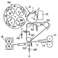
中間転写体として中間転写ベルトを用いた画像形成装置の一例の概略図を図1に示す。
【0004】
図1は、電子写真プロセスを利用したカラー画像形成装置(複写機あるいはレーザービームプリンター)である。中間転写ベルト20には、中抵抗の弾性体を使用している。
【0005】
1は第1の画像担持体として操り返し使用される回転ドラム型の電子写真感光体(以下、感光ドラムと記す)であり、矢示の時計方向に所定の周速度(プロセススピード)をもって回転駆動される。
【0006】
感光ドラム1は、回転過程で1次帯電器2により所定の極性・電位に一様に帯電処理され、次いで不図示の露光手段3(カラー原稿画像の色分解・結像露光光学系、画像情報の時系列電気デジタル画素信号に対応して変調されたレーザービームを出力するレーザースキャナによる走査露光系等)による画像露光を受けることにより、目的のカラー画像の第1の色成分像(例えば、イエロー色成分像)に対応した静電潜像が形成される。
【0007】
次いで、その静電潜像が、第1の現像器(イエロー色現像器41)により第1色であるイエロートナーYにより現像される。この時、第2〜第4の現像器(マゼンタ色現像器42、シアン色現像器43、ブラック色現像器44)の各現像器は作動−オフになっていて感光ドラム1には作用せず、上記第1色のイエロートナー画像は、上記第2〜第4の現像器により影響を受けない。
【0008】
中間転写ベルト20は、時計方向に感光ドラム1と同じ周速度をもって回転駆動されている。感光ドラム1上に形成担持された上記第1色のイエロートナー画像が、感光ドラム1と中間転写ベルト20とのニップ部を通過する過程で、1次転写ローラ62から中間転写ベルト20に印加される1次転写バイアスにより形成される電界により、中間転写ベルト20の外周面に順次中間転写(1次転写)されて行く。中間転写ベルト20に対応する第1色のイエロートナー画像の転写を終えた感光ドラム1の表面は、クリーニング装置13により清掃される。
【0009】
以下、同様に第2色のマゼンタトナー画像、第3色のシアントナー画像、第4色のブラックトナー画像が、順次中間転写ベルト20上に重ね合わせて転写され、目的のカラー画像に対応した合成カラートナー画像が形成される。
【0010】
63は2次転写ローラで、2次転写対向ローラ64に対応し平行に軸受させて中間転写ベルト20の下面部に離間可能な状態に配設してある。感光ドラム1から中間転写ベルト20への第1〜第4色のトナー画像の順次重畳転写のための1次転写バイアスは、トナーとは逆極性(+)でバイアス電源29から印加される。その印加電圧は、例えば、+100V〜+2kVの範囲である。感光ドラム1から中間転写ベルト20への第1〜第3色のトナー画像の1次転写工程において、2次転写ローラ63は中間転写ベルト20から離間することも可能である。
【0011】
中間転写ベルト20上に転写された合成カラートナー画像の第2の画像担持体である転写材Pへの転写は、2次転写ローラ63が中間転写ベルト20に当接されると共に、給紙ローラ11から転写材ガイド10を通って、中間転写ベルト20と2次転写ローラ63との当接ニップに所定のタイミングで転写材Pが給送され、2次転写バイアスが電源28から2次転写ローラ63に印加される。この2次転写バイアスにより中間転写ベルト20から第2の画像担持体である転写材Pへ合成カラートナー画像が転写(2次転写)される。トナー画像の転写を受けた転写材Pは、定着器15へ導入され加熱定着される。
【0012】
転写材Pへの画像転写終了後、中間転写ベルト20にはクリーニング用帯電部材7が当接され、感光ドラム1とは逆極性のバイアスを印加することにより、転写材Pに転写されずに中間転写ベルト20上に残留しているトナー(転写残トナー)に感光ドラム1と逆極性の電荷が付与される。26はバイアス電源である。前記転写残トナーは、感光ドラム1とのニップ部及びその近傍において感光ドラム1に静電的に転写されることにより、中間転写ベルトがクリーニングされる。
【0013】
前述の中間転写ベルトを用いた画像形成装置を有するカラー電子写真装置は、従来の技術である転写ドラム上に第2の画像担持体を張り付けまたは吸着せしめ、そこへ第1の画像担持体上から画像を転写する画像形成装置を有したカラー電子写真装置、例えば、特開昭63−301960号公報中で述べられたごとくの転写装置と比較すると、第2の画像担持体である転写材になんら加工、制御(例えば、グリッパーに把持する、吸着する、曲率をもたせる等)を必要とせずに中間転写ベルトから画像を転写することができるため、封筒、ハガキ、ラベル紙等、薄い紙(40g/m2紙)から厚い紙(200g/m2紙)まで、幅の広狭、長さの長短、あるいは厚さの厚薄によらず、第2の画像担持体を多種多様に選択することができるという利点を有している。
【0014】
このような利点のため、すでに市場においては中間転写ベルトを用いたカラー複写機、カラープリンター等が稼動し始めている。
【0015】
中間転写体等に用いられているベルト及びチューブの製造方法はすでに種々知られている。例えば、特開平3−89357号公報、特開平5−345368号公報では、押出し成形による半導電性ベルトの製造方法が開示されている。また、特開平5−269849号公報では、シートをつなぎ合わせ円筒状とし、ベルトを得る方法が開示されている。また、特開平9−269674号公報では、円筒基材に多層の塗工被膜を形成し、最終的に基材を除くことによりベルトを得る方法が開示されている。また一方、特開平5−77252号公報では、遠心成形法によるシームレスベルトの開示がある。
【0016】
上記の方法は、それぞれ一長一短があり、本発明者等が真に希求している方法ではない。例えば、押出し成形では100μm以下の薄層ベルトの製造はかなりの困難を有し、たとえ可能であったとしても、厚みムラ、それに影響を受ける電気抵抗ムラが生じ易くなり、中間転写体としての性能及び品質安定性に支障をきたすことになる。
【0017】
シートをつなぎ合わせる場合は、つなぎ目の段差及び引張り強度の低下が問題となる。また、塗工、遠心成形法等の溶剤を使用する方法は、塗布液の製造−塗布−成形−溶剤の除去等、工程数、コストが増すものである。更に、溶剤の回収等の環境に影響を及ぼす事項も含んでいる。しかるに、本発明者等は、前述の問題を解決した従来の製造方法とは異なる新規な中間転写ベルトの製造方法を提供するものである。
【0018】
【発明が解決しようとする課題】
本発明の目的は、有機感光体に悪影響を与えず、感光体寿命を長くでき、また低コストで工程数が少なく、多様性に優れた中間転写ベルトの製造方法を提供することである。
【0019】
本発明の別の目的は、第1の画像担持体から中間転写ベルトへの転写効率、及び中間転写ベルトから第2の画像担持体への転写効率が極めて高く、更に中間転写ベルトの繰り返し使用による苛酷な耐久使用を行っても中間転写ベルトの特性に変化がなく、初期と同様な特性を維持し得る中間転写ベルトの製造方法及び画像形成装置を提供することである。
【0020】
本発明の更に別の目的は、画像の微小部分の転写不良の発生しない、所謂中抜け画像のない、均一、均質の画像品質が、第2の画像担持体である紙やOHPシートの種類に依存することなしに達成される中間転写ベルトの製造方法及び画像形成装置を提供することである。
【0021】
【課題を解決するための手段】
本発明に従って、第1の画像担持体上に形成された画像を中間転写ベルトに転写した後、第2の画像担持体上に更に転写する画像形成装置に用いられる中間転写ベルトを製造する方法であって、
(i)成形用原料を押出し機で円筒状に溶融押出ししたものを気体の吹き込みによって膨張させ、これを上方向に引き上げる工程と、
(ii)工程(i)で引き上げたものを切断して中間転写ベルトを得る工程と、
を有する中間転写ベルトの製造方法において、
該工程(i)における押出し成形比が142/118〜142/100であることを特徴とする中間転写ベルトの製造方法、及び、
該製造方法で製造された中間転写ベルトを有する画像形成装置が提供される。
【0022】
【発明の実施の形態】
以下に本発明の製造方法の一態様を説明する。ただし、それにより本発明が制限を何ら受けるものではない。
【0023】
図2に本発明に係る成形装置を示す。本装置は基本的には、押出し機、押出しダイス、気体吹き込み装置より成る。図2は、2層構成ベルト成形用に押出し機100及び110と2基具備しているが、少なくとも本発明においては、1基以上有していればよい。
【0024】
次に、単層の中間転写ベルトの製造方法について述べる。まず、成形用樹脂、導電剤、添加剤等を、所望の処方に基づき、予め予備混合後、混練分散をせしめた成形用原料を押出し機100に具備したホッパー120に投入する。押出し機100は、成形用原料が後工程でのベルト成形が可能となる溶融粘度となり、また原料相互が均一分散するように、設定温度及び押出し機スクリュー構成は選択される。
【0025】
成形用原料は、押出し機100中で溶融混練され、溶融体となり押出しダイス140に入る。押出しダイス140は、気体導入路150が配設されており、気体導入路150により空気等が押出しダイス140に吹き込まれることにより、押出しダイス140を通過した溶融体は、径方向に拡大膨張する。この時、吹き込まれる気体は、空気以外に窒素、二酸化炭素、アルゴン等が挙げられる。
【0026】
膨張した成形体は、冷却リング160により冷却されつつ上方向に引き上げられる。この時、寸法安定ガイド170の間を通過することにより最終的な形状寸法180が決定される。更に、これを所望の巾に切断することにより、本発明の中間転写ベルト190を得ることができる。
【0027】
本発明における、押出し成形比とは、押出しダイス140の口径に対する、押出しダイスを通過し口径が拡大膨張した形状寸法180が得られた時の口径比を表すものである。
すなわち 押出し成形比=成形後の口径/押出しダイス口径 である。
【0028】
前述の説明は、単層ベルトに関してであったが、2層の場合は図2に示される様に、更に押出し機110を配置し、押出し機100の混練溶融体と同時に2層用の押出しダイス140へ押出し機110の混練溶融体を送り込み、2層同時に拡大膨張させ2層ベルトを得ることができる。もちろん、3層以上の時は、層数に応じ相応に押出し機を準備すればよい。
【0029】
図3、図4及び図5に2層及び3層構成の中間転写ベルトを例示する。この様に本発明は、単層のみならず、多層構成の転写ベルトを一段工程で、かつ短時間に寸法精度良く成形することが可能である。この短時間成形が可能ということは、大量生産及び低コスト生産が可能であることを十分示唆するものである。
【0030】
本発明の中間転写ベルトの電気抵抗値及びベルト内の電気抵抗値の一様性は、中間転写ベルトの性能を維持する上で非常に重要な因子である。中間転写ベルトの電気抵抗値が高すぎる場合は、1次転写時及び2次転写時に十分な転写電界を与えることができず転写不良となる。一方、低すぎる場合は、部分的な放電が生じ、やはり転写電界を形成することができない。また、ベルト内の抵抗が不均一であると、前述と同様に部分的な放電すなわち、リークが発生し、1次、2次転写時に印加した電流はそこから逃げ、必要な転写電界を得ることができない。
【0031】
本発明の製造方法においては、押出し成形比の大・小によりベルト内の電気抵抗値の均一性は著しく影響を受ける。押出し成形比が2.80を超えると、押出しダイスを通過後、拡大膨張する工程で、拡大率が大きすぎるため引き上げ方向(軸方向)及び周方向に電気抵抗のムラが生じる。特に、周方向に瞬時に大きく拡大されるため電気抵抗ムラは周方向に大きくなる。
【0032】
押出し成形比が、1.05未満であると押出し成形速度と空気吹き込み量及び速度のバランスを取ることが微妙に難しく、ベルトの形状寸法の不安定性やベルトの肉厚方向にムラが発生し易くなる。このベルト肉厚は、やはり電気抵抗値に影響を与える因子であり、肉厚の不均一はベルト内の抵抗一様性に不具合を与える。押出し成形比が、1.05未満で成形したい場合は、本発明のごときの製造方法では不可能であり、全く異なる成形製造方法を考案する必要がある。
【0033】
製造後の中間転写ベルトの肉厚の範囲は45〜300μmであり、好ましくは50〜270μm、より好ましくは55〜260μmである。本発明は、押出しダイスより押出された混練溶融体が急激に拡大膨張するため、電気抵抗の制御性と相俟って成形体の肉厚はある程度制限を受ける。
【0034】
300μmを超える肉厚は、均一な拡大膨張が得難く、電気抵抗の均一性に難か生じ易く、同時に肉厚が厚い分膜厚の均一性は得難くなる。更に、この膜厚大を有するベルトを中間転写ベルトとして用いる場合、かなりの剛性と乏しい柔軟性のため、円滑な走行性を妨げ、ベルト走行中にタワミ、寄り等が生じ易くなる。45μm未満の肉厚は中間転写ベルトとしての引張り強度の低下、ベルトを張架回転させた繰り返し使用中に緩みが生じ徐々に伸びが発生する等、実用上問題を有するものである。本発明の製造方法では、45μm未満のベルト製造は薄層ゆえ電気抵抗の安定性等が期待でき対応は可能であるが、上記の事実上の問題より適しない。
【0035】
本発明の中間転写ベルトの製造方法に用いられる成形用原料のうちの主たる材料である樹脂としては、例えば、ポリスチレン、クロロポリスチレン、ポリ−α−メチルスチレン、スチレン−ブタジエン共重合体、スチレン−塩化ビニル共重合体、スチレン−酢酸ビニル共重合体、スチレン−マレイン酸共重合体、スチレン−アクリル酸エステル共重合体(スチレン−アクリル酸メチル共重合体、スチレン−アクリル酸エチル共重合体、スチレン−アクリル酸ブチル共重合体、スチレン−アクリル酸オクチル共重合体及びスチレン−アクリル酸フェニル共重合体等)、スチレン−メタクリル酸エステル共重合体(スチレン−メタクリル酸メチル共重合体、スチレン−メタクリル酸エチル共重合体、スチレン−メタクリル酸フェニル共重合体等)、スチレン−α−クロルアクリル酸メチル共重合体、スチレン−アクリロニトリル−アクリル酸エステル共重合体等のスチレン系樹脂(スチレン又はスチレン置換体を含む単重合体又は共重合体)、メタクリル酸メチル樹脂、メタクリル酸ブチル樹脂、アクリル酸エチル樹脂、アクリル酸ブチル樹脂、変性アクリル樹脂(シリコーン変性アクリル樹脂、塩化ビニル樹脂変性アクリル樹脂、アクリル・ウレタン樹脂等)、塩化ビニル樹脂、スチレン−酢酸ビニル共重合体、塩化ビニル−酢酸ビニル共重合体、ロジン変性マレイン酸樹脂、フェノール樹脂、エポキシ樹脂、ポリエステル樹脂、ポリエステルポリウレタン樹脂、ポリエチレン、ポリプロピレン、ポリブタジエン、ポリ塩化ビニリデン、アイオノマー樹脂、ポリウレタン樹脂、シリコーン樹脂、フッ素樹脂、ケトン樹脂、エチレン−エチルアクレート共重合体、キシレン樹脂及びポリビニルブチラール樹脂、ポリイミド樹脂、ポリアミド樹脂、変性ポリフェニレンオキサイド樹脂等からなる群より選ばれる1種類あるいは2種類以上を使用することができる。ただし、上記材料に限定されるものではない。
【0036】
本発明に用いる中間転写ベルトは、転写不良、中抜け画像が生じない程度の硬度が必要であり、その好ましい範囲は100°〜60°、より好ましくは100°〜70°、更に好ましくは100°〜80°であり、その測定方法はJIS−Aの方式に従うものとする。
【0037】
次に、本発明の中間転写ベルトの抵抗値を調整するための抵抗制御剤としては、特に制限されるものではないが、例えば、カーボンブラック、アルミニウムやニッケル等の金属粉末、酸化チタン等の金属酸化物、4級アンモニウム塩含有ポリメタクリル酸メチル、ポリビニルアニリン、ポリビニルピロール、ポリジアセチレン、ポリエチレンイミン、含硼素高分子化合物及びポリピロール等の導電性高分子化合物等からなる群より選ばれる1種類あるいは2種類以上を使用することができる。ただし、これら抵抗制御剤に限定されるものではない。
【0038】
中間転写ベルトの抵抗値の測定方法は、以下の通りである。
(1)中間転写ベルトを図6に示したように張架し、中間転写ベルト20を2本の金属ローラ202及び203で挟み、直流電源、適当な抵抗値を持つ抵抗器、電位差計をつなぐ。
(2)駆動ロールにて中間転写ベルト表面の移動速度が100〜300mm/秒になるようにベルトを駆動する。
(3)直流電源から+1KVを回路に印加し、抵抗器の両端の電位差Vrを電位差計にて読む。なお、測定時の雰囲気は、気温23±5℃、湿度50±10%RHとする。
(4)得られた電位差Vrから、回路に流れる電流値Iを求める。
(5)中間転写ベルトの抵抗値=印加電圧/電流値I。
【0039】
なお、図6において、200は駆動ローラ、201は金属ローラ、204直流電源、205は抵抗器、206は電位差計である。
【0040】
また、第1の画像担持体としては、少なくとも最外層にポリテトラフルホロエチレン(PTFE)微粉末を含有する感光ドラムを用いると、より高い1次転写効率が得られるために好ましい。これは、PTFE微粉末を含有することにより、感光ドラム最外層の表面エネルギーが低下し、トナーの離型性が向上するためではないかと考えられる。
【0041】
【実施例】
以下、実施例をもって本発明を詳細に説明する。実施例中の「部」は重量部である。
【0042】
(実施例1)
ポリカーボネート樹脂 70部
ポリアミド樹脂 30部
導電性カーボンブラック 8部
酸化防止剤 0.5部
【0043】
上記の配合を2軸の押出し混練機で混練せしめ、所望の電気抵抗になるようにカーボン等の添加剤を十分にバインダー中に均一分散させ、1〜2mmの粒径の混練物とした。
【0044】
次に、図2の示される一軸押出し機100のホッパー120へ前記混練物を投入し、設定温度170〜220℃の範囲に調節して押出すことにより溶融体とした。溶融体は、引き続いて、直径100mm、厚さ300μmの円筒状単層用押出しダイス140に導かれた。更に、そこで気体導入路150より空気を吹き込み拡大膨張させ、最終的な形状係数として、直径142mm、肉厚150μmとした。更に、ベルト巾230mmで切断し、中間転写ベルトを得た。これを中間転写ベルト(1)とする。
【0045】
中間転写ベルト(1)の電気抵抗は、7.3×10¹¹Ωであった。また、電気抵抗測定装置(商品名:ハイレスター 三菱化成製)を用い、1000V印加して、上記の中間転写ベルト(1)を周方向に4ヶ所、各位置での軸方向に2ヶ所、計8ヶ所の測定を行い、ベルト内の電気抵抗のバラツキを測定したが、8ヶ所の測定値は1桁以内に収まっていた。同様の位置での肉厚測定のバラツキは、150±20μmの範囲であった。中間転写ベルト(1)を目視観察すると、表面にはブツ、フィシュアイ等の異物、成形不良は見られなかった。
【0046】
この中間転写ベルト(1)を図1に示されるフルカラー電子写真装置に装着し、80g/m2紙にフルカラー画像をプリントし、以下のように転写効率を定義して、転写効率の測定を行った。
【0047】
1次転写効率(感光ドラムから中間転写ベルトヘの転写効率)=
中間転写ベルト上の画像濃度/(感光ドラム上の転写残画像濃度+中間転写ベルト上の画像濃度)。
【0048】
2次転写効率(中間転写ベルトから紙への転写効率)=
紙上の画像濃度/(紙上の画像濃度+中間転写ベルト上の転写残画像濃度)。
【0049】
本実施例では、感光ドラム1として、最外層にPTFE微粉末を含有する有機感光ドラム(OPC感光ドラム)を用いた。そのため、高い1次転写効率が得られた。1次転写効率、2次転写効率はそれぞれ94%、90%であった。
【0050】
なお、中間転写ベルトのクリーニング方式は、クリーニング用帯電部材に1×10⁸Ωの抵抗を持つ弾性ローラを用いた1次転写同時クリーニング方式とし、フルカラー画像5万枚の連続プリントを行った。
【0051】
初期よりベルトの抵抗不均一に起因する画像濃度ムラもなく、5万枚耐久後もベルトの永久伸びに起因する色ズレやクリーニング不良のない良好な画像を得ることができた。更に、表面にトナーのフィルミングもなく、ヒビ割れ、削れ及び摩耗が生ずることなく、初期と同様の表面性のままであった。
【0052】
(実施例2)
ポリエチレンテレフタレート樹脂 100部
導電性酸化スズ 18部
酸化防止剤 0.5部
【0053】
上記の配合を2軸の押出し混練機で混練分散し、均一な混練物を得た。次に、直径118mmの押出しダイスを用い実施例1と同様に成形し、直径142mm、肉厚120μmの中間転写ベルト(2)を得た。
【0054】
この中間転写ベルト(2)の電気抵抗ムラは1桁以内、また肉厚ムラは110〜135μmであった。この中間転写ベルト(2)の電気抵抗は5.0×10¹²Ωであった。また、ベルトの硬度は91°であった。
【0055】
次に、実施例1と同様にして、4万枚のフルカラー画像を繰り返し複写テストを行ったが、ベルトの伸びに起因する色ズレもなく、良好な転写効率から得られる高画像濃度を維持し、中抜け画像も発生しなかった。この時の1次転写効率、2次転写効率は、それぞれ92%、90%であった。4万枚後のベルト表面にトナーのフィルミングは見られず、更にヒビ割れ、折れ曲り、キズも発生しなかった。
【0056】
(比較例1)
直径45mmの押出しダイスを用いた以外は、実施例1と同様にして成形し、直径160mmの中間転写ベルト(3)を得た。中間転写ベルト(3)の電気抵抗は、一応6.9×10¹¹Ωであったが、抵抗測定中の抵抗値が収束せず不安定な測定であった。
【0057】
更に、ベルト内の抵抗の一様性は、3桁以上であり部分的に低抵抗部と高抵抗部が存在していた。肉厚ムラは、150μmを狙っていたが、最小値92μm、最大値221μmとバラツキの大きいものであった。
【0058】
実施例1と同様に複写テストを行ったが、初期から部分的な転写不良、画像濃度薄、(特に2色重ね合わせ時に著しい)画像の微妙な転写抜け等が発生した。5万枚耐久を行ったが、画質は初期レベルより徐々に悪化して行った。しかし、耐久によるヒビ割れ、キズ等は発生しなかった。
【0059】
【発明の効果】
本発明によれば、第1の画像担持体から中間転写ベルトへの転写効率、及び中間転写ベルトから第2の画像担持体への転写効率が極めて高く、更に中間転写ベルトの繰り返し使用による苛酷な繰り返し使用を行っても中間転写ベルトの特性に変化がなく、初期と同様な特性を維持し得る中間転写ベルトの製造方法、及び、該製造方法で製造された中間転写ベルトを有する画像形成装置を提供することが可能となった。
【図面の簡単な説明】
【図1】 中間転写体として中間転写ベルトを用いた画像形成装置の一例の概略図である。
【図2】 本発明に係る中間転写ベルトの成形装置である。
【図3】 2層構造の中間転写ベルトの一部を示す概略構成図である。
【図4】 3層構造の中間転写ベルトの一部を示す概略構成図である。
【図5】 3層構造の中間転写ベルトの全体を示す概略構成図である。
【図6】 中間転写ベルトの抵抗値の測定方法の概略図である。
【符号の説明】
1 感光体ドラム
2 1次帯電器
3 像露光手段
7 クリーニング用帯電部材
10 転写ガイド
11 給紙ローラ
13 クリーニング手段
15 定着手段
20,190 中間転写ベルト
26,28,29 バイアス電源
41 イエロートナー
42 マゼンタトナー
43 シアントナー
44 ブラックトナー
62 1次転写ローラ
63 2次転写ローラ
64 2次転写対向ローラ
100,110 押出し機
120,130 ホッパー
140 押出しダイス
150 気体導入路
160 冷却リング
170 寸法安定ガイド
180 形状寸法
200 駆動ローラ
201,202,203 金属ローラ
204 直流電源
205 抵抗器
206 電位差計
P 転写材[0001]
BACKGROUND OF THE INVENTION
The present invention relates to a method for producing an intermediate transfer belt for use in an electrophotographic image forming apparatus in which a toner image formed on a first image carrier is once transferred to an intermediate transfer belt and further transferred to obtain an image formed product. and related to the image forming apparatus.
[0002]
[Prior art]
An image forming apparatus that uses an intermediate transfer member is a color image forming device that sequentially stacks and transfers a plurality of component color images of color image information and multicolor image information, and outputs an image formed product in which color images and multicolor images are synthesized and reproduced. It is effective as an apparatus, a multicolor image forming apparatus, or an image forming apparatus having a color image forming function and a multicolor image forming function.
[0003]
A schematic view of an example of an image forming apparatus using an intermediate transfer belt as an intermediate transfer member is shown in FIG.
[0004]
FIG. 1 shows a color image forming apparatus (copier or laser beam printer) using an electrophotographic process. The
[0005]
Reference numeral 1 denotes a rotating drum type electrophotographic photosensitive member (hereinafter referred to as a photosensitive drum) that is repeatedly used as a first image bearing member, and is rotated at a predetermined peripheral speed (process speed) in the clockwise direction indicated by an arrow. Is done.
[0006]
The photosensitive drum 1 is uniformly charged to a predetermined polarity / potential by the primary charger 2 during the rotation process, and then exposed to the exposure means 3 (color separation / imaging exposure optical system for color original image, image information). The first color component image (for example, yellow) of the target color image is received by image exposure by a scanning exposure system using a laser scanner that outputs a laser beam modulated in accordance with the time-series electric digital pixel signal of An electrostatic latent image corresponding to the color component image) is formed.
[0007]
Next, the electrostatic latent image is developed with yellow toner Y as the first color by the first developing device (yellow color developing device 41). At this time, the developing devices of the second to fourth developing devices (magenta developing
[0008]
The
[0009]
Similarly, the second color magenta toner image, the third color cyan toner image, and the fourth color black toner image are sequentially superimposed and transferred onto the
[0010]
[0011]
The composite color toner image transferred onto the
[0012]
After the image transfer to the transfer material P is completed, the charging member 7 for cleaning is brought into contact with the
[0013]
In a color electrophotographic apparatus having an image forming apparatus using the above-described intermediate transfer belt, a second image carrier is pasted or adsorbed on a transfer drum, which is a conventional technique, and from there on the first image carrier. Compared with a color electrophotographic apparatus having an image forming apparatus for transferring an image, for example, a transfer apparatus as described in JP-A-63-301960, the transfer material as a second image carrier is not Since images can be transferred from the intermediate transfer belt without the need for processing and control (eg, gripping, adsorbing, giving curvature, etc.), thin paper (40 g / m 2 paper) to thick paper (200 g / m 2 paper), the second image carrier can be selected from a wide variety, regardless of whether it is wide or narrow, long or short, or thick or thin. Has advantages.
[0014]
Because of these advantages, color copiers, color printers and the like using an intermediate transfer belt have already begun to operate in the market.
[0015]
Various methods for manufacturing belts and tubes used for intermediate transfer members and the like are already known. For example, JP-A-3-89357 and JP-A-5-345368 disclose a method for producing a semiconductive belt by extrusion molding. Japanese Patent Application Laid-Open No. 5-269849 discloses a method of joining a sheet into a cylindrical shape to obtain a belt. Japanese Patent Application Laid-Open No. 9-269673 discloses a method of obtaining a belt by forming a multilayer coating film on a cylindrical substrate and finally removing the substrate. On the other hand, JP-A-5-77252 discloses a seamless belt by centrifugal molding.
[0016]
Each of the above methods has advantages and disadvantages, and is not a method that the present inventors are really seeking. For example, in extrusion molding, production of a thin layer belt having a thickness of 100 μm or less has a considerable difficulty, and even if possible, thickness unevenness and electrical resistance unevenness affected by it tend to occur, and performance as an intermediate transfer member In addition, the quality stability will be hindered.
[0017]
When sheets are joined together, there is a problem of a step difference in joints and a decrease in tensile strength. In addition, methods using solvents such as coating and centrifugal molding increase the number of steps and cost, such as production of coating liquid, coating, molding, and removal of solvent. It also includes matters that affect the environment, such as solvent recovery. However, the present inventors provide a novel intermediate transfer belt manufacturing method that is different from the conventional manufacturing method that solves the above-described problems.
[0018]
[Problems to be solved by the invention]
SUMMARY OF THE INVENTION An object of the present invention is to provide a method for producing an intermediate transfer belt , which does not adversely affect an organic photoreceptor, can extend the life of the photoreceptor, is low in cost, has a small number of steps, and has excellent diversity.
[0019]
Another object of the present invention is that the transfer efficiency from the first image carrier to the intermediate transfer belt and the transfer efficiency from the intermediate transfer belt to the second image carrier are extremely high. Further, the intermediate transfer belt is repeatedly used. It is an object of the present invention to provide an intermediate transfer belt manufacturing method and an image forming apparatus capable of maintaining the same characteristics as in the initial stage without changing the characteristics of the intermediate transfer belt even under severe use.
[0020]
Still another object of the present invention is to provide a uniform and homogeneous image quality that does not cause a transfer defect of a minute portion of an image, does not cause a so-called hollow image, and is suitable for the type of paper or OHP sheet as the second image carrier. An object of the present invention is to provide an intermediate transfer belt manufacturing method and an image forming apparatus which can be achieved without depending on the above.
[0021]
[Means for Solving the Problems]
According to the present invention, a method of manufacturing an intermediate transfer belt used in an image forming apparatus for transferring an image formed on a first image carrier to an intermediate transfer belt and further transferring the image onto a second image carrier. There,
(I) a process in which a molding raw material melt-extruded into a cylindrical shape with an extruder is expanded by blowing a gas, and this is pulled upward;
(Ii) cutting the material pulled up in step (i) to obtain an intermediate transfer belt;
In the manufacturing method of the intermediate transfer belt having
An intermediate transfer belt manufacturing method, wherein the extrusion molding ratio in the step (i) is 142/118 to 142/100 , and
An image forming apparatus having an intermediate transfer belt manufactured by the manufacturing method is provided.
[0022]
DETAILED DESCRIPTION OF THE INVENTION
One embodiment of the production method of the present invention will be described below. However, this does not limit the present invention.
[0023]
FIG. 2 shows a molding apparatus according to the present invention. This device basically comprises an extruder, an extrusion die, and a gas blowing device. Although FIG. 2 has two
[0024]
Next, a method for manufacturing a single-layer intermediate transfer belt will be described. First, a molding material, a conductive agent, an additive and the like are premixed in advance based on a desired formulation, and then a molding material kneaded and dispersed is put into a
[0025]
The forming raw material is melt-kneaded in the
[0026]
The expanded molded body is pulled upward while being cooled by the
[0027]
In the present invention, the extrusion molding ratio represents the aperture ratio when the
That is, the extrusion molding ratio = the diameter after molding / the diameter of the extrusion die.
[0028]
The above description was for a single-layer belt, but in the case of two layers, as shown in FIG. 2, an
[0029]
3, 4, and 5 illustrate two-layer and three-layer intermediate transfer belts. Thus, the present invention is not a single layer alone, the transfer belt of a multilayer construction in one step process, and it is possible to dimension accuracy formed shape in a short time. The fact that this short-time molding is possible fully suggests that mass production and low-cost production are possible.
[0030]
The uniformity of the electric resistance value of the intermediate transfer belt and the electric resistance value in the belt of the present invention is a very important factor in maintaining the performance of the intermediate transfer belt. If the electric resistance value of the intermediate transfer belt is too high, a sufficient transfer electric field cannot be applied during primary transfer and secondary transfer, resulting in transfer failure. On the other hand, if it is too low, partial discharge occurs, and a transfer electric field cannot be formed. If the resistance in the belt is not uniform, partial discharge, that is, leakage occurs as described above, and the current applied during the primary and secondary transfer escapes from there to obtain a necessary transfer electric field. I can't.
[0031]
In the production method of the present invention, the uniformity of the electric resistance value in the belt is significantly affected by the size of the extrusion molding. When the extrusion molding ratio exceeds 2.80, in the step of expanding and expanding after passing through the extrusion die, the expansion ratio is too large, and thus uneven electrical resistance occurs in the pulling direction (axial direction) and the circumferential direction. In particular, the electrical resistance unevenness increases in the circumferential direction because it is greatly enlarged instantaneously in the circumferential direction.
[0032]
When the extrusion molding ratio is less than 1.05, it is slightly difficult to balance the extrusion molding speed with the air blowing amount and speed, and the instability of the belt shape and unevenness in the belt thickness direction are likely to occur. Become. The thickness of the belt is also a factor that affects the electric resistance value, and the uneven thickness causes a problem in the resistance uniformity in the belt. Extrusion ratio is, if you want to forming shape in less than 1.05, it is impossible in such a production method of the present invention, it is necessary to devise a completely different molding production process.
[0033]
The thickness range of the intermediate transfer belt after production is 45 to 300 μm, preferably 50 to 270 μm, more preferably 55 to 260 μm. In the present invention, since the kneaded melt extruded from the extrusion die expands rapidly, the thickness of the molded body is limited to some extent in combination with the controllability of electric resistance.
[0034]
When the thickness exceeds 300 μm, it is difficult to obtain uniform expansion and expansion, and it is difficult to obtain uniformity of electrical resistance. At the same time, it is difficult to obtain uniformity of thickness. Further, when a belt having this large film thickness is used as the intermediate transfer belt , smooth running performance is hindered due to considerable rigidity and poor flexibility, and wrinkles and deviations are likely to occur during belt running. A wall thickness of less than 45 μm has practical problems such as a decrease in tensile strength as an intermediate transfer belt , loosening and repeated elongation during repeated use of the belt as it is stretched and rotated. In the production method of the present invention, the production of a belt having a thickness of less than 45 μm can be expected since stability of electric resistance can be expected due to the thin layer, but it is not suitable because of the above-mentioned practical problem.
[0035]
Examples of the resin that is the main material among the molding raw materials used in the method for producing the intermediate transfer belt of the present invention include polystyrene, chloropolystyrene, poly-α-methylstyrene, styrene-butadiene copolymer, and styrene-chloride. Vinyl copolymer, styrene-vinyl acetate copolymer, styrene-maleic acid copolymer, styrene-acrylic acid ester copolymer (styrene-methyl acrylate copolymer, styrene-ethyl acrylate copolymer, styrene- Butyl acrylate copolymer, styrene-octyl acrylate copolymer and styrene-phenyl acrylate copolymer), styrene-methacrylic acid ester copolymer (styrene-methyl methacrylate copolymer, styrene-ethyl methacrylate) Copolymer, styrene-phenyl methacrylate copolymer, etc.) Styrenic resins (monopolymer or copolymer containing styrene or styrene-substituted product) such as styrene-α-chloromethyl acrylate copolymer, styrene-acrylonitrile-acrylate ester copolymer, methyl methacrylate resin, methacryl Acid butyl resin, ethyl acrylate resin, butyl acrylate resin, modified acrylic resin (silicone modified acrylic resin, vinyl chloride resin modified acrylic resin, acrylic / urethane resin, etc.), vinyl chloride resin, styrene-vinyl acetate copolymer, chloride Vinyl-vinyl acetate copolymer, rosin modified maleic acid resin, phenol resin, epoxy resin, polyester resin, polyester polyurethane resin, polyethylene, polypropylene, polybutadiene, polyvinylidene chloride, ionomer resin, polyurethane resin, silicon Use one or more selected from the group consisting of resin, fluororesin, ketone resin, ethylene-ethyl acrylate copolymer, xylene resin and polyvinyl butyral resin, polyimide resin, polyamide resin, modified polyphenylene oxide resin, etc. be able to. However, it is not limited to the said material.
[0036]
The intermediate transfer belt used in the present invention is required to have a hardness that does not cause poor transfer and void images, and a preferable range thereof is 100 ° to 60 °, more preferably 100 ° to 70 °, and still more preferably 100 °. It is ˜80 °, and the measurement method conforms to the method of JIS-A.
[0037]
Next, the resistance control agent for adjusting the resistance value of the intermediate transfer belt of the present invention is not particularly limited, and examples thereof include carbon black, metal powder such as aluminum and nickel, and metal such as titanium oxide. One or two selected from the group consisting of oxides, quaternary ammonium salt-containing polymethyl methacrylate, polyvinylaniline, polyvinylpyrrole, polydiacetylene, polyethyleneimine, boron-containing polymer compounds, and polypyrrole-containing conductive polymer compounds. More than types can be used. However, it is not limited to these resistance control agents.
[0038]
The method for measuring the resistance value of the intermediate transfer belt is as follows.
(1) The intermediate transfer belt is stretched as shown in FIG. 6, the
(2) The belt is driven by the driving roll so that the moving speed of the surface of the intermediate transfer belt is 100 to 300 mm / second.
(3) Apply +1 KV from the DC power supply to the circuit and read the potential difference Vr across the resistor with a potentiometer. In addition, the atmosphere at the time of measurement shall be air temperature 23 ± 5 degreeC and humidity 50 ± 10% RH.
(4) A current value I flowing through the circuit is obtained from the obtained potential difference Vr.
(5) Resistance value of intermediate transfer belt = applied voltage / current value I.
[0039]
In FIG. 6, 200 is a driving roller, 201 is a metal roller, 204 DC power supply, 205 is a resistor, and 206 is a potentiometer.
[0040]
Moreover, as the first image carrier, it is preferable to use a photosensitive drum containing at least the outermost layer of polytetrafluoroethylene (PTFE) fine powder because higher primary transfer efficiency can be obtained. This is considered to be because the surface energy of the outermost layer of the photosensitive drum is lowered and the toner releasability is improved by containing PTFE fine powder.
[0041]
【Example】
Hereinafter, the present invention will be described in detail with reference to examples. “Parts” in the examples are parts by weight.
[0042]
Example 1
Polycarbonate resin 70 parts Polyamide resin 30 parts Conductive carbon black 8 parts Antioxidant 0.5 parts
The above blend was kneaded with a biaxial extrusion kneader, and an additive such as carbon was sufficiently uniformly dispersed in the binder so as to obtain a desired electric resistance to obtain a kneaded product having a particle diameter of 1 to 2 mm.
[0044]
Next, the kneaded material was put into the
[0045]
The electric resistance of the intermediate transfer belt (1) was 7.3 × 10 11 Ω. In addition, using an electrical resistance measuring device (trade name: manufactured by Hirestar Mitsubishi Kasei), 1000 V is applied, and the above intermediate transfer belt (1) is placed at 4 locations in the circumferential direction and 2 locations in the axial direction at each position. Measurements were taken at 8 locations, and variations in electrical resistance within the belt were measured, but the measured values at 8 locations were within one digit. The variation in thickness measurement at the same position was in the range of 150 ± 20 μm. When the intermediate transfer belt (1) was visually observed, no foreign matter such as bumps and fish eyes and molding defects were observed on the surface.
[0046]
This intermediate transfer belt (1) is mounted on the full-color electrophotographic apparatus shown in FIG. 1, a full-color image is printed on 80 g / m 2 paper, and the transfer efficiency is defined as follows to measure the transfer efficiency. It was.
[0047]
Primary transfer efficiency (transfer efficiency from photosensitive drum to intermediate transfer belt) =
Image density on the intermediate transfer belt / (transfer residual image density on the photosensitive drum + image density on the intermediate transfer belt).
[0048]
Secondary transfer efficiency (transfer efficiency from intermediate transfer belt to paper) =
Image density on paper / (image density on paper + transfer residual image density on intermediate transfer belt).
[0049]
In this embodiment, an organic photosensitive drum (OPC photosensitive drum) containing PTFE fine powder in the outermost layer was used as the photosensitive drum 1. Therefore, high primary transfer efficiency was obtained. The primary transfer efficiency and the secondary transfer efficiency were 94% and 90%, respectively.
[0050]
The intermediate transfer belt cleaning method was a primary transfer simultaneous cleaning method using an elastic roller having a resistance of 1 × 10 8 Ω as a cleaning charging member, and continuous printing of 50,000 full-color images was performed.
[0051]
From the beginning, there was no unevenness in image density due to uneven belt resistance, and a good image without color misregistration and poor cleaning due to permanent elongation of the belt could be obtained even after the endurance of 50,000 sheets. Further, there was no toner filming on the surface, and no cracks, scraping or abrasion occurred, and the surface properties were the same as in the initial stage.
[0052]
(Example 2)
The above blend was kneaded and dispersed with a biaxial extrusion kneader to obtain a uniform kneaded product. Then, similarly formed shape as in Example 1 using an extrusion die having a diameter of 118 mm, to obtain a diameter of 142 mm, the intermediate transfer belt thick 120μm (2).
[0054]
The intermediate transfer belt (2) had an electric resistance unevenness of one digit or less and a thickness unevenness of 110 to 135 μm. The electric resistance of the intermediate transfer belt (2) was 5.0 × 10 12 Ω. Further, the hardness of the belt was 91 °.
[0055]
Next, a copy test was repeated for 40,000 full-color images in the same manner as in Example 1, but there was no color shift due to belt elongation, and high image density obtained from good transfer efficiency was maintained. No hollow image was generated. At this time, the primary transfer efficiency and the secondary transfer efficiency were 92% and 90%, respectively. No toner filming was observed on the surface of the belt after 40,000 sheets, and cracking, bending, and scratching were not generated.
[0056]
(Comparative Example 1)
Except for using an extrusion die having a diameter of 45mm is to formed shape in the same manner as in Example 1 to obtain an intermediate transfer belt having a diameter of 160 mm (3). The electric resistance of the intermediate transfer belt (3) was 6.9 × 10 11 Ω for the time being, but the resistance value during resistance measurement did not converge and was an unstable measurement.
[0057]
Furthermore, the uniformity of the resistance in the belt is 3 digits or more, and a low resistance portion and a high resistance portion existed partially. Thickness unevenness was aimed at 150 μm, but was greatly varied with a minimum value of 92 μm and a maximum value of 221 μm.
[0058]
A copying test was performed in the same manner as in Example 1. However, partial transfer failure, thin image density, subtle transfer omission of the image (particularly when two colors were superimposed), and the like occurred from the beginning. Durability of 50,000 sheets was performed, but the image quality gradually deteriorated from the initial level. However, cracks and scratches due to durability did not occur.
[0059]
【The invention's effect】
According to the present invention, the transfer efficiency from the first image carrier to the intermediate transfer belt and the transfer efficiency from the intermediate transfer belt to the second image carrier are extremely high, and further severe due to repeated use of the intermediate transfer belt. An intermediate transfer belt manufacturing method capable of maintaining the same characteristics as the initial stage without changing the characteristics of the intermediate transfer belt even after repeated use , and an image forming apparatus having the intermediate transfer belt manufactured by the manufacturing method It became possible to provide.
[Brief description of the drawings]
FIG. 1 is a schematic view of an example of an image forming apparatus using an intermediate transfer belt as an intermediate transfer member.
FIG. 2 is an intermediate transfer belt molding apparatus according to the present invention.
FIG. 3 is a schematic configuration diagram illustrating a part of an intermediate transfer belt having a two-layer structure.
FIG. 4 is a schematic configuration diagram showing a part of an intermediate transfer belt having a three-layer structure.
FIG. 5 is a schematic configuration diagram illustrating an entire intermediate transfer belt having a three-layer structure.
FIG. 6 is a schematic view of a method for measuring a resistance value of an intermediate transfer belt.
[Explanation of symbols]
DESCRIPTION OF SYMBOLS 1 Photosensitive drum 2 Primary charger 3 Image exposure means 7
Claims (4)
(i)成形用原料を押出し機で円筒状に溶融押出ししたものを気体の吹き込みによって膨張させ、これを上方向に引き上げる工程と、
(ii)工程(i)で引き上げたものを切断して中間転写ベルトを得る工程と、
を有する中間転写ベルトの製造方法において、
該工程(i)における押出し成形比が142/118〜142/100であることを特徴とする中間転写ベルトの製造方法。A method for producing an intermediate transfer belt for use in an image forming apparatus for transferring an image formed on a first image carrier to an intermediate transfer belt and further transferring the image to a second image carrier,
(I) a process in which a molding raw material melt-extruded into a cylindrical shape with an extruder is expanded by blowing a gas, and this is pulled upward;
(Ii) cutting the material pulled up in step (i) to obtain an intermediate transfer belt;
In the manufacturing method of the intermediate transfer belt having
The method for producing an intermediate transfer belt, wherein the extrusion molding ratio in the step (i) is 142/118 to 142/100 .
該中間転写ベルトが、請求項1〜3のいずれかに記載の製造方法で製造された中間転写ベルトであることを特徴とする画像形成装置。In the image forming apparatus for transferring the image formed on the first image carrier to the intermediate transfer belt, and further transferring the image to the second image carrier.
An image forming apparatus, wherein the intermediate transfer belt is an intermediate transfer belt manufactured by the manufacturing method according to claim 1.
Priority Applications (1)
| Application Number | Priority Date | Filing Date | Title |
|---|---|---|---|
| JP03731799A JP3984744B2 (en) | 1999-02-16 | 1999-02-16 | Intermediate transfer belt manufacturing method and image forming apparatus |
Applications Claiming Priority (1)
| Application Number | Priority Date | Filing Date | Title |
|---|---|---|---|
| JP03731799A JP3984744B2 (en) | 1999-02-16 | 1999-02-16 | Intermediate transfer belt manufacturing method and image forming apparatus |
Publications (3)
| Publication Number | Publication Date |
|---|---|
| JP2000235312A JP2000235312A (en) | 2000-08-29 |
| JP2000235312A5 JP2000235312A5 (en) | 2005-01-20 |
| JP3984744B2 true JP3984744B2 (en) | 2007-10-03 |
Family
ID=12494309
Family Applications (1)
| Application Number | Title | Priority Date | Filing Date |
|---|---|---|---|
| JP03731799A Expired - Fee Related JP3984744B2 (en) | 1999-02-16 | 1999-02-16 | Intermediate transfer belt manufacturing method and image forming apparatus |
Country Status (1)
| Country | Link |
|---|---|
| JP (1) | JP3984744B2 (en) |
-
1999
- 1999-02-16 JP JP03731799A patent/JP3984744B2/en not_active Expired - Fee Related
Also Published As
| Publication number | Publication date |
|---|---|
| JP2000235312A (en) | 2000-08-29 |
Similar Documents
| Publication | Publication Date | Title |
|---|---|---|
| JP2001022194A (en) | Belt-like transfer member, its production and image forming device | |
| JP2010250251A (en) | Annular body, annular body stretching device, image forming device, and method for manufacturing the annular body | |
| JP2004287383A (en) | Semiconductive belt and image forming apparatus using the same | |
| US6470165B2 (en) | Process for producing transfer member, transfer member, and image forming apparatus | |
| JP3984744B2 (en) | Intermediate transfer belt manufacturing method and image forming apparatus | |
| US6303072B1 (en) | Process of making an endless belt | |
| JP4350215B2 (en) | Transfer member and image forming apparatus | |
| JP3984745B2 (en) | Intermediate transfer belt manufacturing method and image forming apparatus | |
| JP2000275980A (en) | Intermediate transfer medium, production of intermediate transfer medium and image forming device | |
| JP4332259B2 (en) | Method for manufacturing transfer member | |
| JP4289726B2 (en) | Intermediate transfer member, method for producing the same, and image forming apparatus | |
| JP2000284611A (en) | Transfer member, its production and image forming device | |
| JPH08152759A (en) | Image forming device | |
| JP4309998B2 (en) | Method for manufacturing intermediate transfer member and method for manufacturing transfer member | |
| JP2001051524A (en) | Intermediate transfer body and transfer member, manufacture of them, and image forming device using either of them | |
| JP2004295070A (en) | Semiconductive belt and image forming device using it | |
| JP2001013796A (en) | Interim transfer body, its production and image forming device | |
| JP2000347513A (en) | Intermediate transfer belt, manufacture thereof and image forming device | |
| JP2001005307A (en) | Manufacture of endless belt member, and image forming device | |
| JP2000137388A (en) | Intermediate transfer body, manufacture thereof, and image forming device | |
| JP2000242100A (en) | Production of endless belt, and image forming device | |
| JP3761913B2 (en) | Image forming apparatus | |
| JP2007153510A (en) | Endless belt, method of manufacturing endless belt and image forming device | |
| JPH08160760A (en) | Image forming device | |
| JP2002207370A (en) | Manufacture of belt type transfer member, belt type transfer member and image forming device |
Legal Events
| Date | Code | Title | Description |
|---|---|---|---|
| A521 | Request for written amendment filed |
Free format text: JAPANESE INTERMEDIATE CODE: A523 Effective date: 20040219 |
|
| A621 | Written request for application examination |
Free format text: JAPANESE INTERMEDIATE CODE: A621 Effective date: 20040219 |
|
| A977 | Report on retrieval |
Free format text: JAPANESE INTERMEDIATE CODE: A971007 Effective date: 20061218 |
|
| A131 | Notification of reasons for refusal |
Free format text: JAPANESE INTERMEDIATE CODE: A131 Effective date: 20061221 |
|
| A521 | Request for written amendment filed |
Free format text: JAPANESE INTERMEDIATE CODE: A523 Effective date: 20070209 |
|
| A131 | Notification of reasons for refusal |
Free format text: JAPANESE INTERMEDIATE CODE: A131 Effective date: 20070328 |
|
| A521 | Request for written amendment filed |
Free format text: JAPANESE INTERMEDIATE CODE: A523 Effective date: 20070516 |
|
| TRDD | Decision of grant or rejection written | ||
| A01 | Written decision to grant a patent or to grant a registration (utility model) |
Free format text: JAPANESE INTERMEDIATE CODE: A01 Effective date: 20070620 |
|
| A61 | First payment of annual fees (during grant procedure) |
Free format text: JAPANESE INTERMEDIATE CODE: A61 Effective date: 20070709 |
|
| FPAY | Renewal fee payment (event date is renewal date of database) |
Free format text: PAYMENT UNTIL: 20100713 Year of fee payment: 3 |
|
| R150 | Certificate of patent or registration of utility model |
Free format text: JAPANESE INTERMEDIATE CODE: R150 |
|
| FPAY | Renewal fee payment (event date is renewal date of database) |
Free format text: PAYMENT UNTIL: 20100713 Year of fee payment: 3 |
|
| FPAY | Renewal fee payment (event date is renewal date of database) |
Free format text: PAYMENT UNTIL: 20110713 Year of fee payment: 4 |
|
| FPAY | Renewal fee payment (event date is renewal date of database) |
Free format text: PAYMENT UNTIL: 20120713 Year of fee payment: 5 |
|
| FPAY | Renewal fee payment (event date is renewal date of database) |
Free format text: PAYMENT UNTIL: 20120713 Year of fee payment: 5 |
|
| FPAY | Renewal fee payment (event date is renewal date of database) |
Free format text: PAYMENT UNTIL: 20130713 Year of fee payment: 6 |
|
| LAPS | Cancellation because of no payment of annual fees |