JP3984191B2 - Virtual makeup apparatus and method - Google Patents
Virtual makeup apparatus and method Download PDFInfo
- Publication number
- JP3984191B2 JP3984191B2 JP2003160973A JP2003160973A JP3984191B2 JP 3984191 B2 JP3984191 B2 JP 3984191B2 JP 2003160973 A JP2003160973 A JP 2003160973A JP 2003160973 A JP2003160973 A JP 2003160973A JP 3984191 B2 JP3984191 B2 JP 3984191B2
- Authority
- JP
- Japan
- Prior art keywords
- image
- makeup
- face
- item
- feature
- Prior art date
- Legal status (The legal status is an assumption and is not a legal conclusion. Google has not performed a legal analysis and makes no representation as to the accuracy of the status listed.)
- Expired - Fee Related
Links
Images


Landscapes
- Image Analysis (AREA)
- Image Processing (AREA)
Description
【0001】
【発明の属する技術分野】
本発明は、主として人物の顔画像に対してメイクアップ等の変形を施した画像をディスプレイ等の表示装置に表示するか、あるいは、ネットワークを通じて送信する仮想化粧装置及びその方法に関する。
【0002】
【従来の技術】
口紅やアイシャドウ等の化粧品、あるいはメガネやカラーコンタクトレンズ等は実際に自分がつけた時にどのように見えるかを知りたいという顧客の要求がある。しかしながらこれらの実際に肌等に装着するものは装着自体が面倒であったり、衛生上の問題があったり、異なる商品間の比較が困難であったり、といった問題がある。そこでこれらの商品を実際に装着することなく、装着した状態をバーチャルに画像中で体験できるものは非常に有用である。
【0003】
これまで画像を用いて化粧、髪型、メガネ、カラーコンタクトレンズ等の装着をシミュレートする装置やソフトウエアは静止画を用いた簡易的なものは存在する(例えば、特許文献1)。しかしながら、動画像でユーザの動きに応じて動かすことができなかったため、実際の装着感を得ることができない。また、仮想画像の生成の元となる顔画像中の特徴点や特徴領域の検出がロバストでないため、照明の変化や動き、個人差に十分対応できていない。
【0004】
特徴点の検出を行い、それに対して予め決められた画像を重ねることにより変装画像を表示するものとしては、特許文献2の手法があるが、実画像のシミュレーションという意味では満足できるものではない。
【0005】
また、今日ブロードバンドの普及により、個人間においてもテレビ電話等の顔を見ることができるコミュニケーションツールが普通に使われるようになりつつある。その際に自分の顔や姿を自宅でいるそのままの状態で出て行ってしまうことが問題となると予想される。もちろん、アバタ等を用いることで顔を出さない方法もあるが、それでは臨場感が失われてしまい、折角のブロードバンドの意味がなくなってしまう。しかし、テレビ電話に出るためにわざわざ外出時のような化粧をするのは面倒であるといった問題点がある。
【0006】
【特許文献1】
特開2000−285222公報
【特許文献2】
特開2000−322588公報
【0007】
【発明が解決しようとする課題】
本発明は上記の問題を解決するために、リアルタイムで画像の入力表示を行い、特徴点等の検出をロバストに行うことで、ユーザが自然に装着感を得られる仮想化粧装置及びその方法を提供することを目的とする。
【0008】
【課題を解決するための手段】
請求項1の発明は、少なくとも人物の顔領域を含む動画像における化粧前の各フレームの画像を画像処理して、化粧を施した人物の顔の画像に加工する仮想化粧装置において、顔形状モデルを記憶する顔形状モデル記憶手段と、前記化粧前の各フレームの画像から前記顔に関する特徴点、特徴領域、または、その両方を検出する特徴検出手段と、前記化粧を施すためのアイテムに関する前記アイテムの種類に関するデータと、顔の特徴点、特徴領域、または、その両方と前記アイテムの位置関係を示す位置関係データと、前記アイテムの色、形状、または、塗布範囲を含んでいる化粧データを記憶するデータ記憶手段と、前記記憶されたアイテムの種類から、化粧に必要なアイテムの種類に関するデータを決定する加工方式決定手段と、前記各フレームの画像から検出された特徴点の2次元座標にもとづいて回転角を求めることによって顔の向きを検出する顔方向検出手段と、前記顔の形状モデルを用いて前記各フレームの顔の向きに応じた前記アイテムの塗布位置及び範囲を計算する塗布範囲計算手段と、前記塗布範囲計算手段により計算された前記アイテムの塗布範囲に応じて、動画像の各フレームにおける前記顔の画像を化粧するように画像を加工する画像加工手段と、前記化粧が施された顔の画像を表示する表示手段と、を有することを特徴とする仮想化粧装置である。
【0009】
請求項2の発明は、前記化粧が施された顔の画像を、ネットワークを通じて送信する表示画像送信手段を有することを特徴とする請求項1記載の仮想化粧装置である。
【0010】
請求項3の発明は、前記特徴検出手段は、ネットワークを通じて前記化粧前の画像に関するデータを受信することを特徴とする請求項1記載の仮想化粧装置である。
【0011】
請求項4の前記化粧を施した画像を前記人物の顔の3次元モデルにテクスチャマッピングで貼り付けることを特徴とする請求項1から3のうち少なくとも一項に記載の仮想化粧装置である。
【0012】
請求項5の発明は、前記表示手段において、異なる時刻において化粧を施した画像、異なる顔の方向の化粧を施した画像、異なる解像度の化粧を施した画像、異なる部位の化粧を施した画像、または、異なる化粧を施した画像を同時に表示することを特徴とする請求項1から4のうち少なくとも一項に記載の仮想化粧装置である。
【0013】
請求項6の発明は、前記アイテムが、カラーコンタクトレンズ、アイシャドウ、チーク、口紅、または、タトゥーであることを特徴とする請求項1から5のうち少なくとも一項に記載の仮想化粧装置である。
【0014】
請求項7の発明は、少なくとも人物の顔領域を含む動画像における化粧前の各フレームの画像を画像処理して、化粧を施した人物の顔の画像に加工する仮想化粧方法において、顔形状モデルを記憶する顔形状モデル記憶ステップと、前記化粧前の各フレームの画像から前記顔に関する特徴点、特徴領域、または、その両方を検出する特徴検出ステップと、前記化粧を施すためのアイテムに関する前記アイテムの種類に関するデータと、顔の特徴点、特徴領域、または、その両方と前記アイテムの位置関係を示す位置関係データと、前記アイテムの色、形状、または、塗布範囲を含んでいる化粧データを記憶するデータ記憶ステップと、前記記憶されたアイテムの種類から、化粧に必要なアイテムの種類に関するデータを決定する加工方式決定ステップと、前記各フレームの画像から検出された特徴点の2次元座標にもとづいて回転角を求めることによって顔の向きを検出する顔方向検出ステップと、前記顔の形状モデルの向きに応じて前記アイテムの塗布位置及び範囲を計算する塗布範囲計算ステップと、前記塗布範囲計算手段により計算された前記アイテムの塗布範囲に応じて、動画像の各フレームにおける前記顔の画像を化粧するように画像を加工する画像加工ステップと、前記化粧が施された顔の画像を表示する表示ステップと、を有することを特徴とする仮想化粧方法である。
【0015】
請求項8の発明は、少なくとも人物の顔領域を含む動画像における化粧前の各フレームの画像を画像処理して、化粧を施した人物の顔の画像に加工する仮想化粧方法をコンピュータによって実現するプログラムにおいて、顔形状モデルを記憶する顔形状モデル記憶機能と、前記化粧前の各フレームの画像から前記顔に関する特徴点、特徴領域、または、その両方を検出する特徴検出機能と、前記化粧を施すためのアイテムに関する前記アイテムの種類に関するデータと、顔の特徴点、特徴領域、または、その両方と前記アイテムの位置関係を示す位置関係データと、前記アイテムの色、形状、または、塗布範囲を含んでいる化粧データを記憶するデータ記憶機能と、前記記憶されたアイテムの種類から、化粧に必要なアイテムの種類に関するデータを決定する加工方式決定機能と、前記各フレームの画像から検出された特徴点の2次元座標にもとづいて回転角を求めることによって顔の向きを検出する顔方向検出機能と、前記顔の形状モデルの向きに応じて前記アイテムの塗布位置及び範囲を計算する塗布範囲計算機能と、前記塗布範囲計算手段により計算された前記アイテムの塗布範囲に応じて、動画像の各フレームにおける前記顔の画像を化粧するように画像を加工する画像加工機能と、前記化粧が施された顔の画像を表示する表示機能と、をコンピュータによって実現することを特徴とする仮想化粧方法のプログラムである。
【0019】
【発明の実施の形態】
以下に本発明を詳細に説明する。
【0020】
(第1の実施形態)本発明に関わる第1の実施形態の仮想化粧装置100について、図1から図4に基づいて述べる。
【0021】
なお、本明細書において、「化粧」とは、いわゆる化粧品等をつけて顔をよそおい飾ること、美しく見えるように、表面を磨いたり飾ったりすることに限らず、顔の表面にタトゥーを付けたり、ペインティングを施したりして、化粧前の顔に対し、化粧後の顔の一部、または、全部の色等が異なる状態をいう。
【0022】
(1)仮想化粧装置100の構成
図1は本実施形態の構成を表す図であり、図2は、仮想化粧装置100の概観図例である。
【0023】
仮想化粧装置100は、パーソナルコンピュータ(以下、PCという)にビデオカメラを接続し、CRTもしくは液晶ディスプレイに画像を表示する例である。
【0024】
具体的には人物の瞳領域に対してカラーコンタクトレンズを擬似的につけた画像を表示するものである。
【0025】
画像入力部101は、ビデオカメラであり、動画像を入力する。
【0026】
特徴検出部102では、入力された画像から瞳位置及び虹彩領域の輪郭を抽出する。
【0027】
データ記憶部103では、化粧のアイテムの一つであるカラーコンタクトレンズの種類毎に色、テクスチャー、透明度、サイズ等の化粧データと、顔の特徴点、特徴領域、または、その両方と前記アイテムの位置関係を示す位置関係データを記憶している。
【0028】
加工方式決定部105では、記憶されたカラーコンタクトレンズの種類を選択することができるインターフェースを提供する。
【0029】
画像加工部104においては、選択されたカラーコンタクトレンズのデータに基づき、画像中の対象者の瞳虹彩部分にカラーコンタクトレンズを装着した状態に加工する。
【0030】
表示部106では、CRTもしくは液晶ディスプレイに加工された画像を表示する。
【0031】
各構成部101〜106について以下で詳細に述べる。なお、特徴検出部102、データ記憶部103、画像加工部104、加工方式決定部105の各機能は、PCに記録されているプログラムによって実現される。
【0032】
(2)画像入力部101
画像入力部101では、ビデオカメラから対象となる人物の顔を含む動画像を入力する。
【0033】
例えば、一般的なUSBカメラやデジタルビデオ等、または特別な画像入力デバイスを介して入力する方法もある。
【0034】
入力された動画像は特徴検出部102に逐次送られる。
【0035】
(3)特徴検出部102
特徴検出部102では、入力された画像から特徴点、領域を検出する。
【0036】
本実施形態の場合では、図3に示すような瞳の虹彩領域の輪郭を検出する。瞳虹彩領域の輪郭検出方式を以下で述べる。
【0037】
具体的には、文献1(福井、山口:“形状抽出とパターン照合の組合せによる顔特徴点抽出”,信学論(D−II)vol.J80−D−II,no.9,pp.2170−2177,Aug.1997)で示す方法で瞳位置を検出する。
【0038】
その後、その位置を初期値としてさらに輪郭を検出する。最初に顔領域部分の検出を行ってもよい。
【0039】
瞳輪郭抽出する方法としては、輪郭が円形で近似できる場合においては、文献2(湯浅 他:「パターンとエッジの統合エネルギー最小化に基づく高精度瞳検出」,信学技報,PRMU2000−34,PP.79−84,Jun.2000)が利用できる。
【0040】
先に検出した瞳の中心位置と半径を初期値として、位置と半径を変化させたときのパターン類似度によるパターンエネルギーと円形分離度フィルタの大きさによるエッジエネルギーの組合せによる値が最小になるような位置と半径を求めることで、より精度の高い輪郭を求める方法である。
【0041】
その際、移動部分空間と名づけられた正しい輪郭からずれた位置や半径を基準として切り出したパターンによる部分空間を最小化の際の指標として用いることで、初期値が正解から離れている場合にも対応でき、収束時間を短くすることができる。
【0042】
先に示した文献2では輪郭が円形の場合であったが、この方式は輪郭形状が任意であってもよい。
【0043】
例えば、楕円や輪郭上の複数個のサンプル点の組からなるスプライン曲線等でもよい。
【0044】
楕円の場合には、位置のパラメータ2+形状パラメータ3の5パラメータで表される。
【0045】
また、スプライン曲線の場合には、任意の形状を表現可能な個数のサンプル点数で表現される。
【0046】
但し、任意の形状の場合にはパラメータ数が多くなりすぎて、収束が難しい、あるいは例えできたとしても非常に時間がかかって現実的ではない場合が考えられる。
【0047】
その場合には、ある基準点(例えば瞳の中心)を元に、基準の大きさ(例えば瞳の平均半径、本実施形態の場合には、先に瞳位置を求めた際の分離度フィルタの半径が使用可能である)からのずれを、予め収集した多数の実画像における輪郭形状についてデータを取得しておき、それらのデータを主成分分析することで、パラメータの次元を減らすことが可能である。
【0048】
また、パターンの正規化方法としては位置と形状を元にアフィン変換等で画像を変形させる方法の他に、輪郭に沿って画像を切り出したパターンを用いることができる。
【0049】
(4)データ記憶部103
データ記憶部103においては各選択可能なカラーコンタクトレンズに対して必要な情報を保持する。情報はアイテムに必要な特徴点、特徴領域、または、その特徴点と特徴領域との両方に対する塗布領域の基準位置、サイズ、形状の相対的な位置関係よりなる位置関係データを含む。
【0050】
本実施形態においては、特徴点は瞳の虹彩領域の中心であり、特徴領域は虹彩領域である。
【0051】
カラーコンタクトレンズの中心点と瞳の中心との距離は0とする。
【0052】
また、レンズデータに対してデータ中の基準点と特徴点及び特徴領域を元に算出される基準点とそれに対応するレンズデータの基準点が情報として記録されている。
【0053】
さらに、データ記憶部103は、基準点に対応する化粧データ(色のデータ、テクスチャのデータ、透明度のデータ)が同時に記録されている。
【0054】
(5)加工方式決定部105
加工方式決定部105では、予め入力されてデータ記憶部103で記録されているデータの組を選択する。
【0055】
本実施形態では、化粧のアイテムであるカラーコンタクトレンズの種類を選択する。選択を促すダイアログの例を図4に示す。
【0056】
選択画面では可能なカラーコンタクトレンズを示す画像や、色、文字列等を表示する。
【0057】
(6)画像加工部104
画像加工部104では、検出された特徴領域と選択された位置関係データ、化粧データに基づいて画像の加工を行う。
【0058】
本実施形態では、瞳の虹彩領域に選択されたカラーコンタクトレンズの画像を重ねて表示することにする。
【0059】
カラーコンタクトレンズの化粧データは、第1にレンズ半径と中心からの距離に対応した色と透明度を持つ場合と、第2にレンズの形状及び色やテクスチャー情報を2次元の画像データとして保持する場合が考えられる。
【0060】
本実施形態では第1の場合について述べる。
【0061】
まず、検出された瞳の中心を位置関係データに基づいてレンズの中心に対応させ、虹彩輪郭上の各点をレンズの虹彩対応点に対応させ、アフィン変換で対応半径を算出する。
【0062】
次に、各虹彩内の画素について算出された半径に対応する色や透明度に応じて各画素の値を変更する。例えば、色及び透明度が中心からの距離rの関数としてそれぞれC(r)、α(r)で表される場合には、元の画素値がIorg (r) とすると、変更された画素値I(r)は以下の式で表される。
【0063】
【数1】
![]()
このように透明度を考慮して2つの輝度を重ねあわせる方式をαブレンディングという。
【0065】
(7)画像表示部106
画像表示部106では、画像加工部104で作成された画像をディスプレイ等に表示する。
【0066】
(第2の実施形態)本発明に関わる第2の実施形態の仮想化粧装置500について、図5から図8に基づいて説明する。
【0067】
(1)仮想化粧装置500の構成
本実施形態の仮想化粧装置500は、PCにビデオカメラを接続し、加工した画像をネットワークで送信し、通信相手のディスプレイに画像を表示する例である。
【0068】
具体的には人物の顔領域に対して口紅等のメイクアップを施した画像を表示するものである。
【0069】
図5は本実施形態の構成を表す図である。
【0070】
画像入力部501は、ビデオカメラであり、2Dの動画像を入力する。
【0071】
特徴検出部502では、入力された画像から必要とされる特徴点及び特徴領域を検出する。本実施形態では、瞳位置、鼻孔位置、唇領域とする。
【0072】
データ記憶部503では、対象とするメイクアップのアイテム及び種類毎に色、テクスチャー、透明度、サイズ等の情報を記憶しておく。
【0073】
加工方式決定部505では、記憶されたメイクアップアイテム及び種類、濃さ、グラデーションのパラメータ等を選択することができるインターフェースを提供する。
【0074】
画像加工部504においては、選択されたメイクアップのデータに基づき、画像中の対象者における各メイクアップアイテムの対象領域にメイクアップデータを塗布した状態に加工する。
【0075】
表示画像送信部506では、加工された画像を送信すると共に、その加工された画像を表示する。
【0076】
各構成部について以下で詳細に述べる。なお、特徴検出部502、データ記憶部503、画像加工部504、加工方式決定部505、表示画像送信部506の各機能は、PCに記録されているプログラムによって実現される。
【0077】
(2)画像入力部501
画像入力部501では、カメラからの人物の顔が撮影された画像を入力する。この部分は第1の実施形態と同様である。
【0078】
(3)特徴検出部502
特徴検出部502では最初に瞳位置、虹彩半径、鼻孔位置、口端位置を検出する。それらの検出は第1の実施形態と同様である。
【0079】
それらの特徴点位置、特徴量から以下の塗布領域及び塗布方法を決定する。
【0080】
データ記憶部503には、各メイクアップのアイテム固有の、色、サイズ等の情報の他に、各メイクアップアイテムの種類(アイシャドウ、チーク等)に対応する、必要な特徴点/領域、及びそれらの特徴点/領域からのメイクアップアイテム塗布位置/領域までの相対座標/距離を与える定数値もしくは関数が記録されている。
【0081】
本実施形態においては、チークでは必要な特徴点/領域は両瞳中心位置及び鼻孔位置であり、これらの特徴点からチーク塗布領域(楕円で表現される)の中心座標と長径/短径/回転角を算出する関数が記録される。
【0082】
(3−1)アイシャドウ塗布
アイシャドウ塗布の例を示す。
【0083】
アイシャドウ領域は図6に示すように検出された瞳位置及び虹彩半径を元に算出された領域(斜線部分)について塗布を行う。この領域は、上側は眉で下側はまぶたの下端で規定され、左右においても眉もしくはまぶたの存在領域に規定される。但し、この存在範囲の抽出はそれほど厳密でなくてよい。
【0084】
なぜなら、これらのアイシャドウの塗布は通常、塗布されない領域に対してぼかしを入れるため、塗布領域の端部においては、多少位置がずれても表示上はあまり問題にならないためである。
【0085】
さらに、塗布領域においては、その塗布領域内での元画像の輝度や色の情報を利用して塗布を行うか行わないかを決めることが可能である。例えば、ある一定以上輝度の低いところには塗らないとすればまつげの上等に誤って塗布してしまうことを防ぐことができる。もちろん、直接塗布領域を詳細に抽出しても差し支えない。
【0086】
(3−2)チーク塗布
次に、チーク塗布の例を示す。
【0087】
チーク領域は図7に示すように、瞳の位置及び虹彩半径及び鼻孔位置を元に算出された領域について塗布を行う。チークの場合もアイシャドウの場合と同様に、ぼかしを入れたり、元画像の輝度や色の情報によって塗り分けたりすることが可能である。
【0088】
画素値を決める方法としては、例えば図の中心が(x0,y0)の短径、長径がそれぞれa,bで表される楕円を基準として、中心からの距離をそれらで正規化した距離rを(x,y)の点について(2)式で表されるように規定する。
【0089】
【数2】

このrを(1)式に当てはめたものを利用する。但し、この場合、C(r)を(3)式で表されるものとする。
【0091】
【数3】
(3−3)口紅塗布
次に、口紅塗布の例を示す。
【0093】
口紅領域は図8に示すように、口端位置、あるいはそれに加えて鼻孔や瞳位置等の情報を元に、唇の輪郭を抽出し、その輪郭の内部を基本的には塗布する。
【0094】
但し、その領域内には口を開いた場合には歯や歯茎等が含まれてしまう可能性があるため、内側の輪郭についても抽出するか、もしくは他の輝度や色情報を用いてそれらの領域を無視する必要がある。
【0095】
唇の輪郭を抽出するには例えば口端の2点を元に、予め取得した一般的な唇輪郭の多数のデータを主成分分析して得られた主成分輪郭を元に初期値を生成し、生成された初期値から輪郭を抽出する。この方式は特願平10−065438で開示されている方式である。また、同様に内側の輪郭も抽出し、内側輪郭と外側輪郭の間に対して処理を行ってもよい。
【0096】
(3−4)その他
加工すべきアイテムは前記の特徴に限らない。例えば特徴としては、肌領域、眉領域、まぶた輪郭等が使用可能である。顔領域を決定すれば、その部分にファンデーションを塗ることが可能である。
【0097】
また、塗布領域の決定はこれら6個の特徴点位置のみによらなくてもよいし、すべてを使う必要もない。得られた特徴量から必要なもののみを使用してもよいし、入手可能な得られる特徴量の任意の組合せが利用可能である。
【0098】
さらに、画像を入力して特徴点抽出部502において特徴点を抽出した後に、アイシャドウの塗布、チーク塗布、口紅の塗布を順番に行ってメークアップを完了しても良い。
【0099】
(4)表示画像送信部506
表示画像送信部506はネットワークを通じて作成された画像を送信し、相手方のディスプレイ上に送信された画像を表示する。
【0100】
(第3の実施形態)本発明に関わる第3の実施形態の仮想化粧装置900について、図9から図12に基づいて説明する。
【0101】
(1)仮想化粧装置900の構成
本実施形態の仮想化粧装置900は、ペインティングやタトゥー等を施したと同等の画像を表示し、ユーザが表示されたいくつかのアイテムや色、形状、位置等のパラメータを選択し、選択された画像と同等の効果が実世界で実現できる型紙や具材を作成したり、予め対応する型紙や具材を準備しておき、ユーザの選択に合わせて提供したりする仮想化粧装置900に関するものである。
【0102】
本実施形態の構成図を図9に示す。
【0103】
加工具材配布部907以外の構成は、第1の実施形態と同様である。
【0104】
但し、特徴検出部902においては、ペインティングを施すために、顔の向きの情報が不可欠であるため、顔向き検出を導入する。
【0105】
(2)顔向き検出方法
顔の向きは目鼻等の特徴点の位置関係から簡易的に求めることもできるし、顔領域のパターンを使って求めることも可能である。ペインティングを施した画像の例を図10に示す。
【0106】
文献としては、例えば、特徴点を利用した手法として特開2001−335666、パターンを利用した手法として特開2001−335663、文献3(山田、中島、福井「因子分解法と部分空間法による顔向き推定」信学技法PRMU2001−194,2001)があげられる。
【0107】
ここでは特開2001−335666で提案された特徴点の位置座標から顔の向きを計算する方法について簡単に説明する。
【0108】
まず、顔の映っている画像(互いに異なる顔向きの画像が三フレーム以上)から、目鼻口端等の特徴点(四点以上)を検出する。
【0109】
その特徴点位置座標から、因子分解法(Tomasi,C.and T.Kanade:Technical Report CMU−CS−91−172,CMU(1991);International Journal of Computer Vision,9:2,137−154(1992))を用いて特徴点の3次元座標を求める。
【0110】
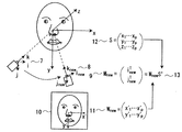
この特徴点の3次元座標を要素にもつ行列を形状行列Sとして保持しておく。向きを求めたい顔の映っている画像が入力されたら、その画像から特徴点を検出し、その特徴点の2次元座標を要素にもつ計測行列Wnewに形状行列Sの一般化逆行列を掛ければ、顔の向きを表す運動行列Mnewが求まり、ロールピッチヨー等の回転角がわかる。運動行列Mnewを計算する様子を図11に示す。なお、図11では、形状行列Sの一般化逆行列をSの上に+をつけた記号で表示ししている。
【0111】
この図では、カメラを固定して顔を動かす様子を相対的に、顔を固定してカメラ向きが変化するとみなしている。特徴点座標は特徴検出部902で検出されたものを利用すればよく、向き自体は行列の掛け算を一度するだけで求まるため、非常に高速な手法であり、フレーム毎に独立に計算できるため誤差が蓄積することもない。
【0112】
このようにして求まる回転角等を元に、ペインティングアイテムにアフィン変形を施し顔画像にマッピングすれば、顔向きに合致した自然なペインティング画像が得られる。
【0113】
(3)加工具材配布部907
加工具材配布部907では図10のような画像を実世界で実現するための具材を配布する。
【0114】
具材としては、図12に示すような型紙を生成する。
【0115】
型紙にはペイントを行う部分には穴が開いていて、簡単に塗りつぶしを行うことができる。
【0116】
また、型紙には図中×で表すような基準点を設定することで誰でも簡単に位置あわせができる。
【0117】
また、型紙は1枚である必要はなく、必要に応じて複数枚生成することで、複雑な形状や、何色も色が存在する場合にも対応可能である。
【0118】
(第4の実施形態)
本発明に関わる第4の実施形態の仮想化粧装置900について、図13から図14に基づいて説明する。
【0119】
本実施形態では、デジタルメイクを行う際の照明環境を考慮した例について述べる。処理の流れを図13に示す。
【0120】
照明環境の記述法は、光源の位置、方向、色、強度等を指定でき、一般のCGで取り扱われているような点光源、面光源を複数用意することで、複雑な光源のシミュレートや、屋外での太陽光等をシミュレートする。
【0121】
顔の各部分での反射率はBRDF(双方向反射関数)等の関数を用いて記述しておき、記述された照明環境に基づいて各画素の輝度値を計算し、表示を行う。
【0122】
次に、カメラにて実際の人物の顔を撮影する際の照明環境を取得し、照明環境をコントロールする方法について述べる。図13のようなフローチャートを用いて行う。
【0123】
まず、顔の3次元モデルを、複数のカメラによる取得、もしくは、単一のカメラにてStructure from Motion技術の手法を用いて作成する。
【0124】
また、文献4(牧「Geotensity拘束による3次元形状獲得−複数光源への対応−」電子情報通信学会 パターン認識・メディア理解研究会研究報告、PRMU99−127,1999)等の方法を用いてもよい。
【0125】
作成した3次元モデルに対して、3次元モデルを構成する複数の面情報について、各面の法線方向等を求めておき、各面についての反射の様子から、光源を推定するために必要な情報を得る。
【0126】
光源の推定方法は、文献5(西野、池内、張「疎な画像列からの光源状況と反射特性の解析」、文化財のデジタル保存自動化手法開発プロジェクト平成13年度成果報告書、pp.86−501)のように、各面での鏡面反射の情報を用いて、複数の点光源方向を求めるものや、文献6(佐藤いまり、佐藤洋一、池内克史、“物体の陰影に基づく光源環境の推定、”情報処理学会論文誌:コンピュータビジョンとイメージメディア「Physics−based VisionとCGの接点」特集号,Vol.41,No.SIG 10(CVIM 1),pp.31−40,December 2000.)のように影の情報をもちいた光源位置の推定法でもよい。
【0127】
図14(a)のように、ある環境で撮影した顔に対して、図14(b)のように別の環境での照明条件での画像を作成する場合を考える。
【0128】
推定した光源の情報を用いて、それらの光源の方向、数、強度等を抑制することによって、3次元モデルに対しての照明環境を変化させ、様々な環境における画像を生成する。
【0129】
また、3次元モデルを陽に用いない方法も考えられる。図14(a)における撮影時の照明条件を考慮して、影、鏡面反射等の特徴的な部分を取り除いた画像を作成する。そして、図14(b)の別の環境での照明条件を考慮し、影、鏡面反射等を画像に付加することで、別の照明条件での画像を得る。
【0130】
また、合成したい、これらの照明環境については、予めいくつかの照明パターンを用意しておいてもよい。例として、「屋内(自宅)」「屋内(レストラン)」「屋外(晴れ)」「屋外(くもり)」等、環境、場所、時間等に応じた照明環境を作成し、合成してもよい。
【0131】
以上のように撮影した環境と違った照明環境の画像を作成することにより、あたかも別の場所で撮影したかのような顔画像を仮想的に作成することができる。
【0132】
(第5の実施形態)以下、図面を参照して本発明の第5の実施形態の仮想化粧装置について説明する。
【0133】
人は化粧をする時に、鏡で自分の顔を見ながら行うことが多い。人は化粧をする時、顔を鏡に近づけたり、あるいは、手鏡等、鏡を動かせる場合は鏡を顔に近づけたりして、顔の見たい部分を拡大して見ようとする。
【0134】
本実施形態の仮想化粧装置は、カメラで撮影した利用者の顔の画像から検出した複数の特徴点から特定の領域(例えば瞼、唇)を決定し、その領域に対してメイクアップを行う。さらには、顔の動きを検知して当該領域を基準に顔を拡大表示する。
【0135】
尚、以下の説明では瞼にアイシャドウを擬似的に塗布する場合を例に説明を行う。
【0136】
図20は本実施形態の仮想化粧装置を実現するためのパーソナルコンピュータ(PC)の構成の一例を説明する図である。
【0137】
このPCは、プロセッサ2001と、メモリ2002と、磁気ディスクドライブ2003と、光ディスクドライブ2004とを備える。
【0138】
更に、CRTやLCD等の表示装置2008とのインターフェース部に相当する画像出力部2005と、キーボードやマウス等の入力装置2009とのインターフェース部に相当する入力受付部2006と、外部装置2010とのインターフェース部に相当する出入力部2007とを備える。
【0139】
出入力部2007としては、例えばUSB(Universal Serial Bus)やIEEE1394等のインターフェースがある。
【0140】
本実施形態の仮想化粧装置では、画像を入力するためのビデオカメラは外部装置2010に相当する。
【0141】
磁気ディスクドライブ2003には、入力された画像に対してメイクアップ等の画像処理を行うプログラムが格納されている。プログラムを実行する際に磁気ディスクドライブ2003からメモリ2002に読み込まれ、プロセッサ2001においてプログラムが実行される。
【0142】
ビデオカメラで撮像された動画像は出入力部2007を経由してメモリ2002にフレーム単位で順次記憶される。プロセッサ2001は記憶された各フレームに対して画像処理を行うとともに、利用者が本装置を操作するためのGUIの生成も行う。プロセッサ2001は処理した画像及び生成したGUIを画像出力部2005を経由して表示装置2008に出力する。表示装置2008は画像及びGUIを表示する。
【0143】
図21は、本実施形態の仮想化粧装置の機能ブロックを説明する図である。
【0144】
本装置は、動画像を入力するビデオカメラである画像入力部2101と、入力された画像から人物の顔の特徴点及び特徴領域を検出する特徴検出部2102と、化粧データ及び位置関係データを記憶するデータ記憶部2103を備える。
【0145】
化粧データとは、化粧のアイテムの一つであるアイシャドウの種類毎の色、テクスチャー、透明度のデータである。位置関係データとは、顔の特徴点及び特徴領域とアイシャドウの塗布領域との位置関係を示すデータである。
【0146】
さらに、利用者が予めデータ記憶部2103に記憶させてあるアイシャドウの種類を選択するためのGUIを提供する加工方式決定部2105と、瞼の部分に選択されたアイシャドウの色を重ねて擬似的に塗布した画像を生成する画像加工部2104と、加工された画像を表示するLCDやCRT等の表示装置である表示部2106と、顔の大きさ・位置・傾きを推定し、推定に基づいて表示部2005を制御して拡大表示させる大きさ・位置情報管理部2107を備える。
【0147】
以下、各部について説明する。
【0148】
(画像入力部2101)画像入力部2001は、ビデオカメラから対象となる人物の顔が映っている動画像を入力する。ビデオカメラとしては、例えばUSB(Universal Serial Bus)接続のカメラや、デジタルビデオカメラ等の一般的なカメラを用いればよい。入力された動画像は、特徴検出部2102に逐次出力される。
【0149】
(特徴検出部2102)特徴検出部2102は、入力された画像から顔の特徴領域を検出する。例えば、瞼にアイシャドウを塗る場合は、図3に示した瞳の虹彩領域の輪郭301を検出する。
【0150】
瞳の虹彩領域輪郭検出は第1の実施形態と同様に文献1に示す手法で行う。検出処理の流れは、特徴点を検出して、特徴点周辺の画素情報を部分空間法により照合していくというものである。以下、概要を図22に基づいて説明する。
【0151】
(S2201 分離度マップ生成)
入力画像全体の各画素毎に図23(A)に示す円形分離度フィルターの出力値を求め、分離度マップを生成する。分離度とは2つの領域の間の画素情報の分離度を表す指標である。本実施形態では、領域2301と領域2302との間の分離度を次式を用いて求める。
【0152】
【数4】
尚、入力画像全体について分離度マップを求めるのではなく、例えばテンプレートマッチングや背景差分法等の画像中における顔の領域を特定する前処理を行った上で分離度マップを求めても良い。
【0154】
(S2202 特徴点候補抽出)
生成した分離度マップにおいて分離度が局所最大値になる点を特徴点候補とする。
【0155】
局所最大値を求める前に分離度マップに対して適宜平滑化等の処理を行っておくと、ノイズの影響を抑制できるので良い。
【0156】
(S2203 パターン類似度算出)
各特徴点候補の近傍から、分離度フィルタの半径rに応じた局所正規化画像を取得する。正規化は半径に応じたアフィン変換で行う。正規化画像と予め瞳周辺の画像から作成しておいた辞書(左の瞳、右の瞳)との類似度を部分空間法により算出する。
【0157】
(S2204 特徴点統合)
各特徴点候補の位置、分離度フィルタの半径、類似度の値に基づいて、正しい瞳の位置を検出する。
【0158】
左の瞳及び右の瞳それぞれについて、S2203パターン類似度算出で求めた類似度の高い順に所定数の特徴点候補若しくは類似度が所定の閾値の以上となる特徴点候補を抽出する。抽出された左右の瞳の特徴点候補を組み合わせて左右の瞳候補を生成する。
【0159】
生成した左右の瞳候補を予め想定した条件と照合して、条件に合致しないものを候補から除外する。条件とは、例えば左右の瞳の間隔(異常に狭い・広い場合は条件外)や、左右の瞳を結ぶ線分の方向(画像中で垂直方向に伸びるような場合は条件外)等である。
【0160】
残った左右の瞳候補のうち、左右それぞれの瞳の類似度の和がもっとも高い組み合わせを左右の瞳とする。
【0161】
(S2205 詳細検出)
瞳の輪郭をさらに正確に求め、瞳の正確な位置を求める。このステップでは文献6(Yuasa et al. "Precise Pupil Contour Detection Based on Minimizing the Energy of Pattern and Edge", Proc.IAPR Workshop on Machine Vision Applications, pp. 232-235, Dec. 2002)の手法を利用する。以下では、この手法の概要を説明する。
【0162】
S2204特徴点統合で得られた瞳位置とその瞳を検出する際に用いた分離度フィルタの半径とを利用して、瞳の輪郭を円形状と仮定して初期形状を作成する。作成した初期形状は楕円パラメータで表現しておく。
【0163】
例えば中心座標が(x0,y0)で半径がrならば、楕円パラメータは、長短径をa,b、回転角をθとして、(x,y,a,b,θ)=(x0,y0,r,r,0)と表すことができる。x、yは中心位置、a、bは楕円の長径、短径、θは目の傾きである。
【0164】
まず、これらの楕円パラメータを初期値として、ガイドパターンを用いて楕円パラメータを大まかに求める。図24はガイドパターンについて説明する図である。
【0165】
ここで用いるガイドパターンは、基準となる瞳周辺の画像(正解パターン)に対して、瞳の半径、瞳の中心位置等のパラメータを様々に変えた画像を生成して主成分分析により作成した辞書である。ここでは楕円パラメータ等を様々に変えて作成した図25に示す11種類の辞書を用いる。尚、正解パターンは利用者自身のものでなくても良い。
【0166】
辞書との照合は部分空間法により行う。複数の辞書の中から最も類似度が高いものを求める。求めた辞書を作成した時のパラメータが、入力した瞳の画像に関するパラメータに近いと推定される。
【0167】
ガイドパターンを利用して推定した楕円パラメータと入力画像とを用いて、楕円パラメータの値を変えながらエッジエネルギーとパターンエネルギーとを算出する。
【0168】
エッジエネルギーとは、当該楕円パラメータを持つ楕円形状の分離度フィルタ(図23(B))を用いて求めた分離度の値の符号を負にしたものである。分離殿値は値の計算には、前述の数4を用いる。
【0169】
パターンエネルギーとは、当該楕円パラメータを基準にして瞳近傍の縮小画像と、予め準備した正解画像及び楕円パラメータから作成した辞書との類似度の値の符号を負にしたものである。辞書との類似度は、部分空間法を用いて求める。
【0170】
このステップでは、楕円パラメータを変化させて上述の二つのエネルギーの和が局所的に最小となる時の楕円パラメータの組を求めることにより、正確な瞳の輪郭を求める。
【0171】
以上のステップにより正確な瞳の輪郭が求まる。瞳の位置は、輪郭の中心として求めることができる。
【0172】
(大きさ・位置情報管理部2107)大きさ・位置情報管理部2107では、特徴検出部2102で求めた瞳の位置、瞳の輪郭半径(楕円パラメータ)から、現在の顔の大きさ、位置、傾きを推定する。そして、顔の大きさの変化率から顔を表示する際の拡大率を求める。
【0173】
顔の大きさ及び傾きは、例えば両瞳を結ぶ線分の長さや傾きから推定する。さらに、左右の瞳の輪郭半径の比率からは顔の回転(首を中心とした回転)を推定する。
【0174】
推定した情報をもとにして、利用者が注目している領域を中心に拡大表示するように、拡大の中心位置と拡大率とを画像加工部2104に通知する。顔において仮想的に化粧を行っている部位(目、頬、唇等)のうち、画像の中心位置に最も近い位置にあると推定された部分を含む領域を、利用者が注目している領域とする。
【0175】
拡大の際に、例えば、顔全体が大きくなりつつある場合は、実際の顔の大きさの変化率を上回る拡大率で拡大するように通知する。このようにすることで、カメラに接近しすぎることを防ぐことができる。図28は拡大表示の一例を説明する図である。最初は顔全体が表示されていても、顔の大きさの変化率から利用者の接近を検出し、利用者が接近しすぎる前に、例えば目を拡大表示させている。
【0176】
人物がカメラに接近し過ぎた状態になると顔全体を撮影することが困難になる。結果として顔の向きや大きさを推定することが困難になる。
【0177】
このような場合は、画面中で注目領域を追跡する。追跡には前述したガイドパターンを応用する。
【0178】
前述したガイドパターンは正解パターンから位置及び瞳半径がズレた状態のパターンであるので、これを用いれば現在の位置及び形状におけるパターンがどの「ズレ方」であるかを推定できる。すなわち、前のフレームにおける「ズレ方」と今のフレームにおける「ズレ方」との違いから、追跡対象となる領域がどのように運動しているかを推定することができる。
【0179】
例えば左右に位置がずれていれば左右の方向の運動していることが分かる。大きさが大きくなっていれば近づいていることがわかる。さらに変形具合から3次元的な運動の推定も可能である。
【0180】
図29は、人物の顔位置がカメラに対して画面内で時間dtの間にx方向に−dx移動した場合の例を説明する図である。時刻t0における領域2901と同じ位置にある、時刻t0+dtにおける領域は、領域2902である。ところが、顔が移動したため、領域2902と同じ(最も類似する)パターンを持つ、時刻t0における領域は、領域2903になる。
【0181】
よって、時刻t0において、ガイドパターンを用いて領域2901のパターンの正解パターンからの「ズレ」を調べておく。そして、時刻t0+dtにおいて、ガイドパターンを用いて領域2902のパターンの正解パターンからの「ズレ」を調べる。両時刻における「ズレ」の差から移動量を推測することができる。
【0182】
(画像加工部2104)画像加工部2104においては、特徴検出部2102において検出された瞳の位置を利用して画像の加工を行なう。また、大きさ・位置情報管理部2107から通知された拡大率及び拡大の中心位置に基づいて画像を拡大する加工を行う。
【0183】
以下の説明では、図26を参照して、右眼の瞼にアイシャドウを仮想的に塗布した画像作成する場合を例に説明する。
【0184】
アイシャドウを仮想的に塗布する手法の概略は次のようになる。瞳の検出された領域、両瞳の位置関係、事前知識として得られる瞳の大きさと目頭及び目尻位置等の関係から、大まかな瞼領域として図26における矩形領域2601を推定する。矩形領域2601内の輝度情報から、瞼に相当する領域、すなわち本領域中で眉や瞳でなない部分、を決定する。瞼の領域に対して、アイシャドウを塗布する加工を施す。
【0185】
矩形領域2601は以下のように決定する。
【0186】
矩形領域2601の下底が、特徴検出部2102で検出した瞳の中心2602を通るように設定する。矩形領域2601の左右の辺は目頭2604や目尻2603の位置を検出して求めることもできるが、本実施形態では瞳の中心2602から目尻寄りに瞳の半径の例えば2.5倍の位置を矩形領域左下端部2605と仮定し、瞳の中心2602から目頭寄りに瞳の半径の例えば3倍の位置を右下端部2606と仮定する。左下端部2605を通り先ほど設定した下底と垂直に交わる線と右下端部3606を通り下底と垂直に交わる線とを左右の辺とする。
【0187】
矩形領域の上底は、下底から瞳の半径の例えば4倍の距離だけ上方に設定する。左右の辺との交点を、左上端部2608、右上端部2609とする。
【0188】
アイシャドウの塗布領域2610の決定方法について述べる。
【0189】
まずはじめに、矩形領域2601全体において、アイシャドウの塗布領域2610とその他の領域間の輝度を分ける閾値を決定する。
【0190】
矩形領域2601における輝度分布は図27のようなヒストグラムとして表わすことができる。矩形領域2601に含まれる領域は輝度の大きさによって大別して3つの領域に分割される。もっとも輝度の低い領域2701は主に虹彩(瞳)内部、まつ毛、眉毛等であり、もっとも輝度の高い領域2703は白目領域であり、残った中間の領域2702が瞼、すなわちアイシャドウを塗布すべき領域となる。
【0191】
矩形領域2601の輝度分布のヒストグラムに判別分析法を適用して、輝度を3分割する閾値Th1及びTh2を決定する(Th1<Th2とする)。判別分析法は、判別基準としてクラス間分散σB 2が最大になるような閾値を決定する方法である。分割による分離度を表わす指標としては、次式で表わされるものを用いることができる。ここではこの値が極大となる時の閾値をTh1およびTh2とする。
【0192】
【数5】
次に、矩形領域2601を上下に2等分する線分2611を設定する。線分2611上の各点から上下方向にそれぞれ塗布領域2610の探索を行う(図中、中抜きの矢印で表わされた方向)。
【0194】
探索は次の手順で行なう。上半分については眉との境界が問題であるから、先に求めた2つの閾値のうち低い方、すなわち閾値Th1を使用する。線分2611上の各点から上方向に移動し、その輝度値がTh1より高ければさらに上へ移動する。輝度値がTh1より低ければ眉領域に達したと判断して探索をやめる。本処理を各点について行なうと、塗布領域2610の上側境界が求まることになる。
【0195】
下半分についても同様である。下半分には輝度の高い部分である白目が存在するので、輝度値が閾値Th2を超えないことを条件とする。また、虹彩領域に入ることも妥当でないので、輝度値が閾値Th1より大きいことも条件とする。
【0196】
さらに、目頭2603と目尻2604の位置を検出するために、白目のラインと矩形領域2601の下底との交点を求める。矩形領域2601の右下端部2606から左に向かって輝度値を調べる。輝度値が閾値Th2を超える点を目頭2604とする。同様に矩形領域2601の左下端部2605から右に向かって輝度値を調べる。輝度値が閾値Th2を超える点を目尻2603とする。
【0197】
矩形領域2601の左の辺と線分2611との交点2612を求める。矩形領域2610のうち交点2612と目尻2603とを結ぶ線分より下にある領域は塗布領域2610には含めない。同様に、矩形領域2601の右の辺と線分2611との交点2613を求める。矩形領域2610のうち交点2613と目頭2604とを結ぶ線分より下にある領域は塗布領域2610には含めない。
【0198】
このようにして、塗布領域2610を求めることができる。画像にノイズがある場合、境界線が不連続になることが考えられる。そこで、あらかじめ矩形領域2601内の輝度を平滑化するか、求められた境界を平滑化するか、或いは、隣接する境界点間に拘束条件を設ける等の処理でそのような状態を避けると良い。本実施形態では、メディアンフィルタを用いて平滑化する。
【0199】
上述のようにして設定した塗布領域2610に対してアイシャドウを仮想的に塗布する加工を施す。第1の実施形態と同様にαブレンディングを用いて加工する。本実施形態では次式を用いる。
【0200】
【数6】
上式の(x,y)は瞳の中心2602からの相対的な位置である。D1は瞳の半径の3倍で、D2は瞳の半径の4倍の値とする。
【0202】
尚、顔が傾いている場合は、人物の顔向きを検出し、それに従って前述の矩形領域2601をアフィン変換等で変換して処理を行い、最後に逆変換すればよい。
【0203】
(データ記憶部2103、加工方式決定部2105、表示部2106)データ記憶部2103、加工方式決定部2105及び表示部2106は第1の実施形態と同様である。
【0204】
(第5の実施形態の効果)以上に説明したように、本実施形態の仮想化粧装置ならば、利用者がカメラに近づいたのを検出し、利用者が見ようとしていると推定される部位を拡大表示させることができる。
【0205】
(第6の実施形態)本実施形態の仮想化粧装置は、カメラで複数の人物の顔が撮像された場合に、各々の人物に対して異なる加工を行えるようにしたものである。以下、第5の実施形態と異なる部分を中心に説明する。
【0206】
図30は本実施形態の仮想化粧装置の構成を説明する図である。本装置は、動画像を入力するビデオカメラである画像入力部2101と、入力された画像から人物の顔の特徴点及び特徴領域を検出する特徴検出部2102と、入力された画像中から人物の顔に相当する領域を検出する顔領域検出部3001と、検出された顔画像情報から顔認識用の辞書を生成して記憶しておく顔辞書生成記憶部3002と、化粧データ及び位置関係データを記憶するデータ記憶部2103を備える。
【0207】
化粧データとは、化粧のアイテムの一つであるアイシャドウの種類毎の色、テクスチャー、透明度のデータである。位置関係データとは、顔の特徴点及び特徴領域とアイシャドウの塗布領域との位置関係を示すデータである。
【0208】
さらに、利用者が予めデータ記憶部2103に記憶させてあるアイシャドウの種類を選択するためのGUIを提供する加工方式決定部2105と、瞼の部分に選択されたアイシャドウの色を重ねて擬似的に塗布した画像を生成する画像加工部2104と、加工された画像を表示するLCDやCRT等の表示装置である表示部2106と、顔の大きさ・位置・傾きを推定し、推定に基づいて表示部2005を制御して拡大表示させる大きさ・位置情報管理部2107を備える。
【0209】
本装置では、入力された画像から顔領域検出部3001が顔の領域を検出する。検出された顔の領域と特徴検出部2102で得られる情報とを用いて、大きさ・位置情報管理部2107は人物の顔が画像中のどの位置にどの大きさで何個あるかを推定する。
【0210】
そして、時間的・空間的に連続した位置にある顔については同一人物と推定し、大きさ・位置の情報に識別子を割り当てて記憶する。画像加工部2104は識別子を利用して人物毎に異なる加工を行うとともに、行った加工の内容を識別子とともにデータ記憶部2103に記憶させておく。
【0211】
大きさ・位置情報管理部2107は、一定数以上同一人物の画像が得られた場合、顔領域検出部3001に対して顔認識を行うように通知を行い、識別子と顔の位置とを出力する。
【0212】
顔領域検出部3001は通知を受けて、顔辞書生成記憶部3002に、識別子と顔辞書の生成を行うのに必要な顔領域の画素情報を出力する。また、顔領域検出部3001は顔認識を行って識別子による人物特定を行う。
【0213】
本実施形態では、顔認識は文献7(山口他、「動画像を用いた顔認識システム」、信学技法PRMU97−50、1997)で提案されている相互部分空間法を利用する。そのため、顔辞書の生成は、顔領域の画素情報から特徴ベクトルを求め、特徴ベクトルを主成分分析した結果の上位の固有ベクトルで張られる部分空間を求めることに対応する。
【0214】
顔領域検出部3001における顔認識では、顔辞書生成と同様にして入力画像の顔領域から特徴ベクトル若しくは部分空間を求め、顔辞書生成期億部3002に記憶されている顔辞書との類似度を算出する。
【0215】
顔認識を行うことによって、画像中に複数人の顔が同時に映っていても正確に人物を識別して各個人に対して加工を行うことができる。
【0216】
尚、人物が一度画像から消えてから再び画像中に出現した場合等でも、顔領域検出部3001で顔辞書と照合を行えば同一人物かを識別することができる。そして、顔辞書に登録された人であれば、以前に割り当てられた識別子を用いてデータ記憶部2103に格納された加工情報を検索し、以前に行った加工を再現することが可能である。従って、本実施形態ならば、追跡中に一度見失っても再び追跡が可能となる。
【0217】
(変形例)
(1)変形例1
第2の実施形態において、このように化粧等の変形を施した場合、受信する側において、送信側の人物の顔が変わりすぎて、送信側人物を特定できなくなるといった問題が起こる可能性がある。
【0218】
そこで、受信側のセキュリティを保つために、化粧等の変形を施す前の画像で顔による個人認証を行い、その結果を同時に送信する。そうすることで、確かに送信側人物がその人であるとわかるので、受信側人物が安心して会話できる。化粧等の変形を施す前の画像で認識するので、認識率が低下したりしない。もちろん顔認識以外の方法で個人認証を行っても差し支えない。顔認識による個人認証には、特開平9−251534で開示されている方法を利用する。
【0219】
(2)変形例2
第2の実施形態において、個々のユーザ特有の3Dモデル、動きのモデル装着、塗布の嗜好性、色や具材の選択等をユーザパラメータと呼ぶ。こういったユーザパラメータをユーザ毎に保存することもできる。ログインユーザ情報もしくはカメラからの画像を利用した個人認証、もしくはその他の指紋やパスワード等による個人認証によってこれらのユーザパラメータを呼び出すことができる。
【0220】
(3)変形例3
メイクアップデータ保持やメイクアップアイテムの付加を行うのはサーバであってもよいし、自分または相手のローカルの装置でもかまわない。
【0221】
また、互いに通信を行う場合にあっては、その間に仲介するサーバがあってもなくてもよい。
【0222】
さらに、表示部106、906においても、通信を行う例においては自分の表示装置及び送信される側の表示装置のいずれかもしくは双方に元の画像及び加工済み画像の双方もしくはいずれかをどのような組合せで表示を行っても差し支えない。
【0223】
なお、通常は加工済みデータのみを表示するのが望ましい。
【0224】
(4)変形例4
第1の実施形態においては、カラーコンタクトレンズ装着のシミュレーションをする場合について述べたが、メイクアップアイテムはカラーコンタクトレンズに限らない。
【0225】
第2の実施形態で述べた一般的なメイクアップアイテムのいずれでも実施可能である。
【0226】
また、第2の実施形態においてカラーコンタクトレンズを装着してもよい。
【0227】
第3、4の実施形態についても同様である。
【0228】
さらに、それ以外にも頭髪やアクセサリ等であってもよい。
【0229】
(5)変形例5
第1〜4の実施形態において1台のカメラから2D動画像を入力する例について述べたが、カメラは一台に限る必要はない。
【0230】
すなわち、複数のカメラを用いて一般的なステレオ手法により、3Dのデータを取得してもよい。その場合には2Dによって得られた場合よりもより多くの特徴が得られる可能性がある。
【0231】
例えば、チークを塗布する際に、頬骨の出ている位置等を基準位置として使用することができる。
【0232】
さらに、3Dデータは複数台のカメラでなく、一台であっても、モーションステレオを用いれば取得可能であり、そのようなデータを利用してもよい。
【0233】
なお、カメラ以外のデバイスによって3Dデータを取得しても差し支えない。
【0234】
(6)変形例6
第1、2の実施形態では顔領域の特徴のみを用いたが、第3の実施形態のように顔の向きを検出し、その向きの変化を加工方式に加味してもよい。
【0235】
例えば、顔向きに応じて塗布位置をアフィン変換することにより、変化させるといったことが考えれる。この変換は単純なアフィン変換のみならず、予め一般的な顔の形状モデルを準備しておき、顔向きが何度の時に塗布位置や範囲がどのように変化するかを予め計算しておいたり、その場で計算したりしてもよい。
【0236】
また、顔の形状モデルは1つだけでなく、複数個準備しておき、ユーザの形状に合ったものを選択してもよい。
【0237】
このように、ユーザまたは一般的な3次元形状モデルが何らかの方法で得られる場合には、2次元画像に対して加工を施した加工済画像をそれらの形状モデルにテクスチャとしてマッピングを行なうことで、良好な3次元表示が得られることになる。
【0238】
(7)変形例7
第1〜4の実施形態においては、PCを使用する例について述べたが、画像入力装置と画像表示装置を備えていれば、上記処理を行う部分はPCである必要はない。
【0239】
例えば、半導体チップやそれらの組み合わせたボード等の処理ハードウエア、組み込みコンピュータ、ゲーム機等でも差し支えない。
【0240】
(8)変形例8
第1〜4の実施形態においては、リアルタイムで入力画像に対して即時に表示を行う例について述べたが、これもその用途に限られるものではなく、画像を予め取得しておいて随時処理や表示を行ったり、処理結果を記憶メディアに保存したりしても差し支えない。
【0241】
(9)変形例9
第1〜4の実施形態については、予めメイクアップアイテムに対するデータセットが用意されている例について述べたが、これについても必ずしもはじめから用意されている必要はなく、ユーザが自由に実際のデータを入力できるシステムであってもよい。
【0242】
例えば、口紅の例について述べる。
【0243】
ユーザは、画像入力装置であるカメラで口紅を塗る前の画像と塗った後の画像の双方を同じ条件で撮影し、それらの双方から特徴(すなわち、この場合においては唇の輪郭)の抽出を行い、唇領域における画像特徴、すなわち、色やテクスチャーの差を抽出し、それらのデータを所定の方式によって加工することにより、メイクアップデータを作成する。
【0244】
加工の方法としては、以下の方法が考えられる。
【0245】
まず、抽出された唇領域の色、例えばRGBそれぞれの平均値を口紅塗布前後で算出し、それらの差をメイクアップデータとする。
【0246】
また、元から存在せず、ユーザが入力する場合でもなく、予めインターネットやCD−ROM等のメディアを介してメイクアップアイテムやそのデータを配布してもよい。
【0247】
さらに、先に述べたメイクアップアイテムデータの入力装置はユーザの端末には必ずしも必要ではなく、これらの配布サイトに対してのみその機能があってよい。
【0248】
(10)変形例10
第1〜4の実施形態において、メイクアップデータの持ち方は、背景のない状態で元となる具材をカメラで撮像した画像、元となる具材を対象物に対して装着もしくは塗布した状態、及び、装着もしくは塗布する以前の状態における対象物の画像をカメラで撮像し、その差分情報を記録したものでもよい。また、それらの撮像を異なる対象物に対して行った情報の平均値もしくはなんらかの統計操作を施したもの等がある。
【0249】
また、それらの撮像は同じ対象物の異なる大きさや向きに対して行い、それらを大きさや向きのパラメータで正規化を行うかもしくはそれらのパラメータに対して分類して保持するとさらによい。
【0250】
さらに、それ以外にもデータは撮影条件等にかかわらず同じ画像を一部そのまま貼り付けたり、部分的にパールやグロスによるつや等の効果を与えたりすることもできる。
【0251】
例えば、付けひげ等は前者の例である。
【0252】
(11)変形例11
第1〜4の実施形態においては、メガネをかけていない場合について述べたが、最終的な状態としてメガネをかけた状態でもかまわない場合には問題がないが、最終状態としてメガネをはずした状態にしたい場合には、メガネの領域を検出してメガネを取り除いた画像を作成してもよい。
【0253】
(12)変形例12
第3の実施形態において、表示部906で表示された画像と同等のものを実世界において作成する具材をメイクアップデータから作成する例を述べたが、これについては第1、2の実施形態において、カラーコンタクトレンズや化粧具材を実施に作成してもよいし、具材ではなく、その補助となる型紙のようなものを作成あるいは、予め準備しておいても差し支えない。
【0254】
(13)変形例13
第1〜4の実施形態において、顔特徴等の検出に失敗した場合には、そのフレームの画像を表示せず、検出されている以前のフレームの画像にそのフレームにおいて検出された特徴により加工を施した画像を表示することもできる。
【0255】
こうすることで、特徴の検出に失敗した場合でも、不自然にならない表示が可能である。
【0256】
(14)変形例14
第1〜4の実施形態において、表示は一画面のみの場合について述べたが、これは2つ以上の画像を含んでも差し支えない。
【0257】
例えば、図15のように時刻の異なる画像を並べて表示したり、図16のように方向の異なる画像を並べて表示したり、図17のように異なる具材によって加工された画像を並べて表示したりしてもかまわない。
【0258】
また、その場合、具材は同じ具材でかつ、色のみ違うパターンを表示すればより選択の際にユーザの補助として有効である。
【0259】
さらに、図18のように、画像中の一部のみを拡大して表示する機能があればより好ましい。
【0260】
(15)変形例15
第1〜4の実施形態において、画像の加工をαブレンディングによって行う例をあげたが、他の方法でも差し支えない。
【0261】
例えば、当該範囲の色情報のうち色相のみを入れ替えるといった方法も考えられる。
【0262】
(16)変形例16
第1〜4の実施形態において、2Dの画像を表示する例について述べたが、これには限らない。
【0263】
例えば、3Dデータを作成した場合には、これを3Dのビューアで表示してもよい。
【0264】
(17)変形例17
第1、3、4の実施形態において、表示部106、906はディスプレイ等の装置に表示する場合について述べたが、例えばユーザの顔にプロジェクタ等で直接照射してもかまわない。
【0265】
(18)変形例18
メイクは、例えば、チークを頬の筋肉の流れに沿って塗布したり、眉墨を眉近辺の骨格に沿って目尻の位置の延長まで塗布したりする等、個人の顔の形状に合わせて行われると自然な仕上がりになる。
【0266】
従って、入力画像を元に作成された顔の3次元形状を見てメイクアップアーティスト等がその形状に合ったメイクを施すことができれば、個人の形状に合ったより自然なメイクを提案できる。そのような場合に3Dエディタが有効である。
【0267】
また、予め用意されているメイクアイテムの中から選択されたものが自動的にメイクが塗布されるのではなく、自由にメイクやペインティングを創作したい場合にも、3Dエディタが有効である。
【0268】
3Dエディタとしては、例えば図19に示すような、3次元形状データを読み込み、その形状を3D表示する表示部106と、色パレットや、ブラシ、ペンシル、パフ、消しゴム等のメイクツールパレットや、ぼかし効果、つや効果、テクスチャ等の効果ツールパレット等をもつ。メイクツールや効果ツール等を使って、データから読み込まれた3Dオブジェクトの上にメイクやペインティング等を好きな形や色で書き込み、作成した書き込みオブジェクトは、オブジェクト毎に或いはグルーピングされたオブジェクトをまとめてメイクアイテムとして保存しておくこともできる。
【0269】
メイクエディタは、メイクを施される対象者本人が使ってもよいし、メイクアップアーティスト等が使っても良い。
【0270】
また、メイクを専門に学ぶためのツールとしても利用できる。
【0271】
従って、自分の好きなメイクを編み出すために顔画像を撮影しエディタを使うこともあれば、顔画像を撮影しエディタを使ってメイクを施した画像あるいはデータを専門家に送信し、コメントや修正を加えて送り返すこともあれば、顔画像を撮影しメイクを施さずに顔画像を送信し、送信された顔画像を受信側が受け取り、受信側でエディタを使って3Dオブジェクトにメイクを施し、メイクを施した画像や3Dデータを送り返すこともある。
【0272】
ここでいう「メイク」は、通常のメイクに限ったものではなく、舞台用メイク(例えば、宝塚メイク、動物メイク、歌舞伎メイク等)やペインティングを含んでもかまわない。この舞台用メイクでは、俳優の顔を予め撮影しておき、メイクアップアーティストが舞台に合わせたメイクを編み出すために利用することもできる。ペインティングも自分の好みのデザインを作ることができる。
【0273】
以上、3次元メイクエディタについて述べたが、画像に直接書き込むことのできる2次元エディタでもかまわない。このようなエディタ機能により、自由にメイクアイテムを作成、編集できる。
【0274】
実際にメイクを物理的に施す際、メイクを初めてする者にとってはメイクの仕方が全くわからないためメイクの仕方を知りたいという要求や、初心者でなくてもプロのテクニックを知りたいという要求等がある。このような要求に応え、メイクを物理的に施すための支援ツールとして、ファンデーション、眉墨、チーク等の塗り方を順に表示する機能をメイクエディタに組み込むこともできる。
【0275】
表示は2次元でも3次元でもかまわないし、必ずしもメイクエディタに組み込まれている必要はなく、支援ツールが独立していてもよい。このような支援ツールは、子供等を対象に歌舞伎メイク等がどのように施されるかを見せる等、後世に無形文化を伝えていくためのツールとしても利用できる。
【0276】
(19)変形例19
第1、3の実施形態では、メイクアップ等の変形の結果はディスプレイ等の表示装置に表示していたが、直接ユーザの顔等にメイクアップ等の結果を反映してもかまわない。
【0277】
これは、装置が機械的に行ってもよいし、人間が行ってもよい。例えば、ブラシ等を用いてユーザの顔にペインティングを施すといったことが考えられる。
【0278】
(20)変形例20
第1、3の実施形態において、加工方式決定部105,505はブラシやタブレット等の入力装置を用いて、ユーザの顔や模型の顔やディスプレイ上の顔等に直接塗布してもよい。
【0279】
例えば、ユーザの顔にブラシを用いて塗る場合は、ユーザにブラシ用のセンサをつけた面を装着する等して塗る場所を判別するといったことが考えられる。
【0280】
(21)変形例21
第2の実施形態において、表示部506がネットワークを経由して接続されている例を示したが、加工方式決定部505もネットワークを経由して一つまたは複数存在してもよい。
【0281】
例えば、離れた場所にいるメイクアップアーティスト等がユーザをメイクアップしたり、ユーザのメイクアップを修正したり、アドバイスを与えるといったことが考えられる。
【0282】
また、ネットワークの相手側の加工方式決定部505を操作するのは人間だけでなく、計算機等によって操作されてもよい。
【0283】
さらに、ネットワークの相手側を操作するのは複数でもよい。その場合は、操作するのは人間だけでなく計算機も組み合わせてもよく、それぞれが同時に操作をしてもかまわない。
【0284】
(22)変形例22
仮想化粧装置において仮想的に施された化粧についてユーザが興味を持った場合、そのような化粧を実際に行うための方法や必要となる製品についての情報を入手したいという欲求が生じることが考えられる。
【0285】
本変形例においては上述のユーザ欲求を満足するための方法として、仮想メイクを実際に行いたいと考えるユーザをサポートする機能について詳述する。
【0286】
ユーザが施された化粧を実際にそのまま自分の顔に行いたいと考えた場合、まず必要な化粧用製品の情報を入手する必要がある。そこで予め施されるメイクの種類毎にそれぞれ必要とされる化粧用製品のリストを用意しておき、ユーザがそのリストを画面上で閲覧できるようにしておく。
【0287】
このリストは化粧用製品のメーカ、販売価格、含有成分等の情報を含んでおり、ユーザがその製品を購入しようとする際に重要な参考情報となる。閲覧するタイミングとしては、ユーザが自分で製品リスト表示ボタンを押す「自発的閲覧」や、ユーザが同じ化粧を一定時間表示させているとシステムが自動的に製品リストを表示する「自動表示」等が考えられる。
【0288】
ユーザが実際にリストの中から選んだ製品を購入する方法として、ユーザが直接販売店に足を運ぶこと無くネット上で購入処理を行う方法が考えられる。この方法はいわゆる「ネット通販」と呼ばれるものと類似した購入システムであり、ユーザは欲しい製品をリストから選択し、購入ボタンを押せば自動的にその情報が契約している販売店へ送信され、製品が送られてくるシステムである。
【0289】
(23)変形例23
第2の実施形態において、通信を相互で行っている場合、相手画像からメイクアップデータを抽出し、そのデータに基づいてメイクアップシミュレーションを行ってもよい。
【0290】
(24)変形例24
第1〜4の実施形態において、メイクアップデータの組み合わせは通信を行う場合には通信の相手によって予め準備しておいてもよい。
【0291】
また、その組み合わせは有名人に似せたもの等を予め準備しておいてもよい。
【0292】
メイクアップデータを作成する場合に雑誌等の写真をスキャナで取り込み、その画像からメイクアップデータを抽出し、同じメイクを再現する機能があってもよい。
【0293】
また、選択されたメイクアップデータの組み合わせに基づいて必要なアイテムのリスト出力してもよい。
【0294】
また、メイクアップのイメージやパラメータを選択する際に、画面中に表示されたダイアログをマウスで選択する例については述べたが、これらの選択は音声を用いても差し支えない。
【0295】
その場合には、仮想化粧装置にマイク等の音声を取り込むデバイスから音声を取り込み、音声認識装置により取り込まれた音声で表されたコマンドを実行する。例えば、「もっとシャープに」等とイメージを伝えたり、「もう少し下に」等と位置を指定したり、「もっと赤く」「アイシャドウはブルーに」等さまざまな指定が可能となる。ユーザはいちいち手を動かさないでいいので、非常に使い勝手がよくなる。
【0296】
また、メイクアップデータやその組み合わせは予め定められたメイクアップランゲージとして保存することも可能である。この言語はたとえば口元や目元と言った部位毎あるいは口紅やアイシャドウといったアイテム毎に指定し、それぞれに位置や形状、色や質感をパラメータとして指定する。それらの組み合わせによって顔全体のメイクアップ方式を定めることができる。それらのデータは一般的なデータとして定めることもできるし、メイクアップアイテムを製造するメーカ毎に個々に定めてもよい。一度決められればメイクアップを言語で再現できるため、たとえば通信する際にデータを削減できるし、だれでも同じメイクが再現できる。
【0297】
(25)変形例25
第5の実施形態では、注目領域を瞳領域として説明したが、これに限らない。例えば、利用者が指定した場所を注目領域としても良いし、画像の中心を固定して注目領域としても良い。また、特開平11−175246号公報において提案されている注視位置の検出手法を用いて、利用者の注視位置を注目領域としても良い。
【0298】
また、第5の実施形態において瞳の追跡の際にガイドパターンを用いる例を挙げた。顔が動かなくても瞳だけが動くため、拡大する領域が必要以上に揺れ動く可能性がある。この問題を防ぐためには、例えば、ガイドパターン生成の際に目頭及び目尻に対する瞳の相対位置を予め保持しておき追跡時に比較すると良い。
【0299】
(26)変形例26
図31(A)及び図31(B)は、第5の実施形態の仮想化粧装置における、画像入力部2101および表示部2106の一例を説明する図である。本変形例では、画像入力部2101であるカメラ3101と、表示部2106であるディスプレイ3102とが一体になっており、かつ、利用者が手で持つための持ち手3103が付いている。
【0300】
図31(A)は利用者がカメラ3101から離れた状態で、ディスプレイ3102に顔全体が映っている場合である。図31(B)は利用者がカメラ3101に目を近づけた状態で、ディスプレイ3102には目の周辺が表示されている。
【0301】
画像入力部2101および表示部2106を、このような一体構造にすると、利用者は実際に手鏡を使用しているような感覚で使用することができるので良い。
【0302】
その他の部分(例えば特徴検出部2102、画像加工部2104等)との通信は、ケーブルを介して行っても良いし、無線を用いてもよい。
【0303】
尚、本変形例は、カメラ付PDA、カメラ付携帯電話、カメラ付タブレット型PC等の、カメラ付携帯端末を用いて実現しても良い。
【0304】
【発明の効果】
以上説明したように本発明によれば、リアルタイムで画像の入力表示を行い、特徴点等の検出をロバストに行うことで、ユーザが位置合わせ等にわずらわされることなく、自然に装着感を得られる仮想化粧装置が可能となる。
【図面の簡単な説明】
【図1】 第1の実施形態の構成図である。
【図2】 第1の実施形態の外観図である。
【図3】 瞳虹彩領域の検出例の図である。
【図4】 選択ダイアログの例の図である。
【図5】 第2の実施形態の構成図である。
【図6】 アイシャドウ塗布領域の例の図である。
【図7】 チーク塗布領域の例の図である。
【図8】 口紅塗布領域の例の図である。
【図9】 第3の実施形態の構成図である。
【図10】 ペインティングを施した例の図である。
【図11】 運動行列を計算する様子である。
【図12】 加工具材の例の図である。
【図13】 第4の実施形態の処理の流れである。
【図14】 別環境の照明条件での画像を作成する例の図である。
【図15】 変形例14における複数画像表示の例におけるその1の図である。
【図16】 変形例14における複数画像表示の例におけるその2の図である。
【図17】 変形例14における複数画像表示の例におけるその3の図である。
【図18】 変形例14における拡大画像表示の例の図である。
【図19】 変形例18における3Dエディタの例の図である。
【図20】 第5の実施形態でプログラムを動作させるコンピュータの例。
【図21】 第5の実施形態の構成図である。
【図22】 第5の実施形態の特徴検出部の処理の流れを説明する図。
【図23】 (A)瞳虹彩領域の検出例。(B)瞳虹彩領域の検出例。
【図24】 ガイドパターン用の正規化画像の例。
【図25】 ガイドパターンのパラメータ例。
【図26】 アイシャドウ塗布領域の例。
【図27】 輝度ヒストグラムによる閾値決定の説明図。
【図28】 第5の実施形態の表示例。
【図29】 注目領域の追跡手法の説明図。
【図30】 第6の実施形態の構成図。
【図31】 (A)変形例26において顔全体を表示させた図。(B)変形例26において目の周辺を拡大表示させた図。
【符号の説明】
100 仮想化粧装置
101 画像入力部
102 特徴検出部
103 データ記憶部
104 画像加工部
105 加工方式決定部
106 表示部
2001 プロセッサ
2002 メモリ
2003 磁気ディスクドライブ
2004 光ディスクドライブ
2005 画像出力部
2006 入力受付部
2007 出入力部
2008 表示装置
2009 入力装置
2010 外部装置
2101 画像入力部
2102 特徴検出部
2103 データ記憶部
2104 画像加工部
2105 加工方式決定部
2106 表示部
2107 大きさ・位置情報管理部
3001 顔領域検出部
3002 顔辞書生成部[0001]
BACKGROUND OF THE INVENTION
The present invention mainly relates to a virtual makeup apparatus and method for displaying an image obtained by deforming a face image of a person on a display device such as a display or transmitting the image through a network.
[0002]
[Prior art]
There is a customer demand to know how cosmetics such as lipsticks and eye shadows, or glasses and color contact lenses look when they are actually worn. However, those actually attached to the skin and the like have problems such as troublesome mounting itself, sanitary problems, and difficulty in comparing different products. Therefore, it is very useful to be able to experience the wearing state virtually in the image without actually wearing these products.
[0003]
Up to now, there are simple devices and software that use images to simulate the wearing of makeup, hairstyles, glasses, color contact lenses, and the like (for example, Patent Document 1). However, since the moving image cannot be moved according to the user's movement, an actual wearing feeling cannot be obtained. In addition, since detection of feature points and feature regions in a face image that is a source of generation of a virtual image is not robust, it cannot sufficiently cope with changes in lighting, movement, and individual differences.
[0004]
Japanese Patent Laid-Open No. 2003-26058 discloses a technique for detecting feature points and displaying a disguise image by superimposing a predetermined image on the feature point. However, this method is not satisfactory in terms of real image simulation.
[0005]
In addition, with the spread of broadband today, communication tools that allow faces to be seen between individuals, such as videophones, are becoming commonplace. In that case, it is expected that it will be a problem that you leave your face and figure while you are at home. Of course, there is a method that doesn't show up by using avatars, etc., but this loses the sense of realism, and the meaning of broadband is lost. However, there is a problem that it is troublesome to put on makeup like when going out to answer a videophone.
[0006]
[Patent Document 1]
JP 2000-285222 A
[Patent Document 2]
JP 2000-322588 A
[0007]
[Problems to be solved by the invention]
In order to solve the above-mentioned problems, the present invention provides a virtual makeup apparatus and a method therefor, in which a user can naturally get a feeling of wearing by performing image input display in real time and robustly detecting feature points and the like. The purpose is to do.
[0008]
[Means for Solving the Problems]
According to the first aspect of the present invention, there is provided a virtual makeup device for processing a face image of each frame before makeup in a moving image including at least a person's face area, and processing the image into a face image of a person who has applied makeup. A face shape model storage means for storing the feature, a feature detection means for detecting a feature point, a feature region, or both of the face from the image of each frame before the makeup, and the item for the item for applying makeup Data relating to the type of item, positional relationship data indicating the positional relationship between the feature point, feature region, or both of the item and the item, and makeup data including the color, shape, or application range of the item Data storage means, processing method determination means for determining data related to the type of item necessary for makeup from the stored item type, and Face direction detecting means for detecting a face direction by obtaining a rotation angle based on a two-dimensional coordinate of a feature point detected from a frame image, and a face direction of each frame using the face shape model An application range calculation unit that calculates the application position and range of the item in response, and makeup of the face image in each frame of the moving image according to the application range of the item calculated by the application range calculation unit A virtual makeup apparatus comprising: an image processing means for processing an image; and a display means for displaying an image of the face on which the makeup has been applied.
[0009]
According to a second aspect of the present invention, there is provided a virtual makeup apparatus according to the first aspect, further comprising display image transmission means for transmitting the face image to which the makeup has been applied through a network.
[0010]
The invention according to
[0011]
The image according to
[0012]
The invention of
[0013]
The invention according to
[0014]
According to a seventh aspect of the present invention, there is provided a face shape model in a virtual makeup method in which an image of each frame before makeup in a moving image including at least a person's face area is processed into an image of a person's face subjected to makeup. Storing a face shape model, a feature detection step of detecting feature points, feature regions, or both of the face from the image of each frame before makeup, and the item relating to an item for applying makeup Data relating to the type of item, positional relationship data indicating the positional relationship between the feature point, feature region, or both of the item and the item, and makeup data including the color, shape, or application range of the item Data storage step and processing method determination for determining data relating to the item type necessary for makeup from the stored item type A face direction detecting step for detecting a face direction by obtaining a rotation angle based on two-dimensional coordinates of the feature points detected from the images of the frames, and the direction of the shape model of the face An application range calculation step for calculating the application position and range of the item, and an image so as to make up the face image in each frame of the moving image according to the application range of the item calculated by the application range calculation means A virtual makeup method comprising: an image processing step for processing; and a display step for displaying an image of the face on which the makeup has been applied.
[0015]
According to the invention of
[0019]
DETAILED DESCRIPTION OF THE INVENTION
The present invention is described in detail below.
[0020]
(First Embodiment) A
[0021]
In this specification, “makeup” is not limited to decorating the face with so-called cosmetics and so on. In other words, a state in which a part or all of the color of the face after makeup is different from the face before makeup after painting is performed.
[0022]
(1) Configuration of
FIG. 1 is a diagram illustrating the configuration of the present embodiment, and FIG. 2 is an example of an overview diagram of the
[0023]
The
[0024]
Specifically, an image in which a color contact lens is artificially attached to a human pupil region is displayed.
[0025]
The
[0026]
The
[0027]
In the
[0028]
The processing
[0029]
Based on the selected color contact lens data, the
[0030]
The
[0031]
Each component 101-106 is described in detail below. Note that each function of the
[0032]
(2)
The
[0033]
For example, there is a method of inputting via a general USB camera, digital video, or a special image input device.
[0034]
The input moving image is sequentially sent to the
[0035]
(3)
The
[0036]
In the present embodiment, the contour of the iris region of the pupil as shown in FIG. 3 is detected. The outline detection method of the pupil iris region will be described below.
[0037]
Specifically, Reference 1 (Fukui, Yamaguchi: “Face Feature Point Extraction by Combination of Shape Extraction and Pattern Matching”, Science Theory (D-II) vol. J80-D-II, no. 9, pp. 2170 -2177, Aug. 1997), the pupil position is detected.
[0038]
Thereafter, the contour is further detected using the position as an initial value. First, the face area portion may be detected.
[0039]
As a method for extracting the pupil contour, in the case where the contour can be approximated by a circle, Reference 2 (Yuasa et al .: “High-precision pupil detection based on minimizing integrated energy of pattern and edge”, IEICE Technical Report, PRMU2000-34, PP. 79-84, Jun. 2000) can be used.
[0040]
The initial value is the center position and radius of the previously detected pupil, and the value based on the combination of the pattern energy based on the pattern similarity and the edge energy based on the size of the circular separability filter when the position and radius are changed is minimized. This is a method for obtaining a more accurate contour by obtaining a correct position and radius.
[0041]
At that time, even if the initial value is far from the correct answer by using the partial space by the pattern cut out based on the position and radius shifted from the correct contour named moving subspace as a reference It is possible to cope with it, and the convergence time can be shortened.
[0042]
In
[0043]
For example, it may be an ellipse or a spline curve composed of a set of a plurality of sample points on the contour.
[0044]
In the case of an ellipse, it is represented by 5 parameters of
[0045]
In the case of a spline curve, it is expressed by the number of sample points that can express an arbitrary shape.
[0046]
However, in the case of an arbitrary shape, the number of parameters increases too much, so that it is difficult to converge, or even if it can be compared, it takes a very long time and is not realistic.
[0047]
In that case, based on a certain reference point (for example, the center of the pupil), the size of the reference (for example, the average radius of the pupil, in the case of the present embodiment, in the case of the separation filter when the pupil position is first determined) It is possible to reduce the dimensionality of parameters by acquiring data about the outline shape in a large number of pre-collected real images and performing principal component analysis of these data. is there.
[0048]
As a pattern normalization method, in addition to a method of deforming an image by affine transformation or the like based on a position and a shape, a pattern obtained by cutting an image along an outline can be used.
[0049]
(4)
The
[0050]
In the present embodiment, the feature point is the center of the iris region of the pupil, and the feature region is the iris region.
[0051]
The distance between the center point of the color contact lens and the center of the pupil is zero.
[0052]
In addition, a reference point in the data, a reference point calculated based on the feature point and the feature region, and a reference point of the lens data corresponding to the reference point in the data are recorded as information.
[0053]
Further, the
[0054]
(5) Processing
The processing
[0055]
In this embodiment, the type of color contact lens that is a cosmetic item is selected. An example of a dialog prompting selection is shown in FIG.
[0056]
On the selection screen, an image showing possible color contact lenses, colors, character strings, and the like are displayed.
[0057]
(6)
The
[0058]
In the present embodiment, an image of the selected color contact lens is displayed in an overlapping manner on the iris region of the pupil.
[0059]
The color contact lens makeup data includes first the color and transparency corresponding to the lens radius and distance from the center, and second the case where the lens shape, color and texture information are stored as two-dimensional image data. Can be considered.
[0060]
In the present embodiment, the first case will be described.
[0061]
First, the detected center of the pupil is made to correspond to the center of the lens based on the positional relationship data, each point on the iris contour is made to correspond to the iris corresponding point of the lens, and the corresponding radius is calculated by affine transformation.
[0062]
Next, the value of each pixel is changed according to the color and transparency corresponding to the radius calculated for the pixels in each iris. For example, if the color and transparency are expressed as C (r) and α (r), respectively, as a function of the distance r from the center, and the original pixel value is Iorg (r), the changed pixel value I (R) is represented by the following equation.
[0063]
[Expression 1]
![]()
Such a method of superimposing two luminances in consideration of transparency is called α blending.
[0065]
(7)
The
[0066]
(Second Embodiment) A virtual makeup apparatus 500 according to a second embodiment of the present invention will be described with reference to FIGS.
[0067]
(1) Configuration of virtual makeup apparatus 500
The virtual makeup device 500 of this embodiment is an example in which a video camera is connected to a PC, the processed image is transmitted over a network, and the image is displayed on the display of the communication partner.
[0068]
Specifically, an image in which makeup such as lipstick is applied to the face area of a person is displayed.
[0069]
FIG. 5 is a diagram showing the configuration of the present embodiment.
[0070]
The
[0071]
The
[0072]
The
[0073]
The processing
[0074]
Based on the selected makeup data, the
[0075]
The display
[0076]
Each component will be described in detail below. Note that the functions of the
[0077]
(2)
The
[0078]
(3)
The
[0079]
The following application region and application method are determined from the feature point positions and feature amounts.
[0080]
In the
[0081]
In the present embodiment, the feature points / regions necessary for cheek are the center position and nostril position of both pupils, and the center coordinates and major axis / minor axis / rotation of the cheek application region (expressed by an ellipse) from these feature points. The function for calculating the corner is recorded.
[0082]
(3-1) Eye shadow application
An example of eye shadow application will be described.
[0083]
As shown in FIG. 6, the eye shadow region is applied to a region (shaded portion) calculated based on the detected pupil position and iris radius. This area is defined by the eyebrows on the upper side and the lower end of the eyelids on the lower side, and is also defined by the eyebrow or eyelid existing area on the left and right. However, the extraction of the existence range may not be so strict.
[0084]
This is because the application of these eye shadows usually blurs the uncoated area, so that even if the position of the edge of the coated area is slightly shifted, there is no problem in display.
[0085]
Further, in the application area, it is possible to decide whether or not to apply the information by using the luminance and color information of the original image in the application area. For example, if it is not applied to a place where the luminance is lower than a certain level, it can be prevented from being applied by mistake on the eyelashes. Of course, the application area may be directly extracted in detail.
[0086]
(3-2) Teak application
Next, an example of cheek application will be shown.
[0087]
As shown in FIG. 7, the cheek region is applied to a region calculated based on the pupil position, iris radius, and nostril position. In the case of cheeks, as in the case of eye shadows, it is possible to blur or to paint differently according to the luminance and color information of the original image.
[0088]
As a method for determining the pixel value, for example, an ellipse whose center is (x0, y0) and whose major axis is represented by a and b is used as a reference, and a distance r obtained by normalizing the distance from the center is used. The point of (x, y) is defined as expressed by equation (2).
[0089]
[Expression 2]
This r is applied to the equation (1). However, in this case, C (r) is represented by the expression (3).
[0091]
[Equation 3]
(3-3) Lipstick application
Next, an example of lipstick application will be shown.
[0093]
In the lipstick region, as shown in FIG. 8, the outline of the lips is extracted based on the information on the mouth end position or in addition to the nostril and the pupil position, and the inside of the outline is basically applied.
[0094]
However, if the mouth is opened in that area, teeth, gums, etc. may be included, so either extract the inner contour or use other brightness and color information It is necessary to ignore the area.
[0095]
In order to extract the lip contour, for example, based on the principal component contour obtained by principal component analysis of a large number of general lip contour data obtained in advance based on two points at the mouth edge, an initial value is generated. The contour is extracted from the generated initial value. This method is the method disclosed in Japanese Patent Application No. 10-065438. Similarly, the inner contour may be extracted, and the process may be performed between the inner contour and the outer contour.
[0096]
(3-4) Other
Items to be processed are not limited to the above features. For example, as a feature, a skin region, an eyebrow region, an eyelid contour, or the like can be used. Once the face area is determined, it is possible to apply a foundation to the area.
[0097]
Further, the application area may not be determined only by these six feature point positions, and it is not necessary to use all of them. Only necessary ones from the obtained feature values may be used, or any combination of available feature values obtained can be used.
[0098]
Furthermore, after the image is input and the feature points are extracted by the feature
[0099]
(4) Display
The display
[0100]
(Third Embodiment) A virtual makeup apparatus 900 according to a third embodiment of the present invention will be described with reference to FIGS.
[0101]
(1) Configuration of virtual makeup apparatus 900
The virtual makeup apparatus 900 of the present embodiment displays an image equivalent to a painting or tattoo, and the user selects some items displayed and parameters such as color, shape, position, etc. Related to a virtual makeup apparatus 900 that creates a pattern or material that can achieve the same effect as a real image, or prepares a corresponding pattern or material in advance and provides it according to the user's selection It is.
[0102]
FIG. 9 shows a configuration diagram of the present embodiment.
[0103]
The configuration other than the processing tool
[0104]
However, since the face detection information is indispensable in the
[0105]
(2) Face orientation detection method
The orientation of the face can be easily obtained from the positional relationship of feature points such as the eyes and nose, or can be obtained using a pattern of the face area. An example of a painted image is shown in FIG.
[0106]
References include, for example, Japanese Patent Application Laid-Open No. 2001-335666 as a method using feature points, Japanese Patent Application Laid-Open No. 2001-335663 as a method using patterns, and Reference 3 (Yamada, Nakajima, Fukui “Face Decomposition and Subspace Method Face Orientation” Estimate ”, a scientific technique PRMU 2001-194, 2001).
[0107]
Here, a method for calculating the orientation of the face from the position coordinates of the feature points proposed in Japanese Patent Laid-Open No. 2001-335666 will be briefly described.
[0108]
First, feature points (four or more points) such as the eyes, nose and mouth ends are detected from an image showing a face (three or more frames having different face orientations).
[0109]
From the feature point position coordinates, factorization method (Tomasi, C. and T. Kanade: Technical Report CMU-CS-91-172, CMU (1991); International Journal of Computer Vision, 9: 2, 137-154 (1992). )) To determine the three-dimensional coordinates of the feature points.
[0110]
A matrix having the three-dimensional coordinates of the feature points as elements is held as a shape matrix S. When an image showing the face whose orientation is to be obtained is input, a feature point is detected from the image, and a measurement matrix Wnew having the two-dimensional coordinates of the feature point as an element is multiplied by a generalized inverse matrix of the shape matrix S. Then, the motion matrix Mnew representing the face orientation is obtained, and the rotation angle such as roll pitch yaw can be known. FIG. 11 shows how the motion matrix Mnew is calculated. In FIG. 11, the generalized inverse matrix of the shape matrix S is represented by a symbol with + on S.
[0111]
In this figure, it is assumed that the camera is fixed and the face is moved relatively, while the face is fixed and the camera orientation is changed. The feature point coordinates may be those detected by the
[0112]
If a painting item is subjected to affine deformation and mapped to a face image based on the rotation angle obtained in this way, a natural painting image that matches the face direction can be obtained.
[0113]
(3) Processing tool
The processing tool
[0114]
As the material, a pattern as shown in FIG. 12 is generated.
[0115]
The pattern paper has holes in the paint area, so it can be easily filled.
[0116]
In addition, anyone can easily align the pattern by setting a reference point as indicated by x in the drawing.
[0117]
Further, it is not necessary to have a single pattern paper, and it is possible to cope with a complicated shape or a number of colors by generating a plurality of paper patterns as necessary.
[0118]
(Fourth embodiment)
A virtual makeup apparatus 900 according to a fourth embodiment of the present invention will be described with reference to FIGS.
[0119]
In this embodiment, an example in consideration of the lighting environment when performing digital makeup will be described. The flow of processing is shown in FIG.
[0120]
The lighting environment description method can specify the position, direction, color, intensity, etc. of the light source. By preparing multiple point light sources and surface light sources that are handled by general CG, it is possible to simulate complex light sources. Simulate outdoor sunlight.
[0121]
The reflectance of each part of the face is described using a function such as BRDF (bidirectional reflection function), and the luminance value of each pixel is calculated based on the described illumination environment for display.
[0122]
Next, a description will be given of a method of acquiring an illumination environment when photographing an actual human face with a camera and controlling the illumination environment. This is performed using a flowchart as shown in FIG.
[0123]
First, a three-dimensional model of a face is acquired by using a plurality of cameras or created by using a structure from motion technique using a single camera.
[0124]
Alternatively, a method such as Reference 4 (Maki “Acquisition of three-dimensional shape by Geotensity constraint—corresponding to a plurality of light sources—” IEICE Pattern Recognition / Media Understanding Study Group Report, PRMU99-127, 1999) may be used. .
[0125]
Necessary for estimating the light source from the state of reflection on each surface by obtaining the normal direction of each surface for a plurality of surface information constituting the three-dimensional model for the created three-dimensional model. get information.
[0126]
The light source estimation method is described in Reference 5 (Nishino, Ikeuchi, Zhang “Analysis of light source conditions and reflection characteristics from sparse image sequences”, Development project for digital preservation automation technique for cultural assets, 2001 results report, pp. 86- 501), using information of specular reflection on each surface to obtain a plurality of point light source directions, Document 6 (Imari Sato, Yoichi Sato, Katsushi Ikeuchi, “Light source environment based on object shading” Estimated, “Information Processing Society Journal: Computer Vision and Image Media“ Physics-based Vision and CG ”Special Issue, Vol. 41, No. SIG 10 (CVIM 1), pp. 31-40, December 2000.) A light source position estimation method using shadow information may be used.
[0127]
Consider the case of creating an image under illumination conditions in another environment as shown in FIG. 14B for a face photographed in a certain environment as shown in FIG.
[0128]
Using the estimated light source information, the lighting environment for the three-dimensional model is changed by suppressing the direction, number, intensity, and the like of the light sources, and images in various environments are generated.
[0129]
A method that does not explicitly use the three-dimensional model is also conceivable. In consideration of the illumination conditions at the time of photographing in FIG. 14A, an image is created by removing characteristic portions such as shadows and specular reflections. Then, in consideration of the illumination condition in another environment of FIG. 14B, an image under another illumination condition is obtained by adding a shadow, a specular reflection or the like to the image.
[0130]
In addition, for these lighting environments to be combined, several lighting patterns may be prepared in advance. For example, an illumination environment corresponding to the environment, location, time, etc., such as “indoor (home)”, “indoor (restaurant)”, “outdoor (clear)”, “outdoor (cloudy)”, etc. may be created and combined.
[0131]
By creating an image of an illumination environment different from the environment where the image was taken as described above, it is possible to virtually create a face image as if the image was taken at another location.
[0132]
(Fifth Embodiment) A virtual makeup apparatus according to a fifth embodiment of the present invention will be described below with reference to the drawings.
[0133]
People often do makeup while looking at their faces in the mirror. When applying makeup, a person tries to enlarge the part he wants to see by moving his face close to the mirror or by moving the mirror close to his face, such as a hand mirror.
[0134]
The virtual makeup apparatus according to the present embodiment determines a specific region (for example, eyelids and lips) from a plurality of feature points detected from a user's face image captured by a camera, and performs makeup on the region. Furthermore, the movement of the face is detected and the face is enlarged and displayed based on the area.
[0135]
In the following description, a case where eye shadow is applied in a pseudo manner is described as an example.
[0136]
FIG. 20 is a diagram for explaining an example of the configuration of a personal computer (PC) for realizing the virtual makeup apparatus of the present embodiment.
[0137]
The PC includes a
[0138]
Further, an
[0139]
Examples of the input /
[0140]
In the virtual makeup device of this embodiment, the video camera for inputting an image corresponds to the external device 2010.
[0141]
The magnetic disk drive 2003 stores a program for performing image processing such as makeup on the input image. When the program is executed, the program is read from the magnetic disk drive 2003 to the memory 2002, and the program is executed by the
[0142]
The moving images picked up by the video camera are sequentially stored in the memory 2002 in units of frames via the input /
[0143]
FIG. 21 is a diagram illustrating functional blocks of the virtual makeup device according to the present embodiment.
[0144]
The apparatus stores an
[0145]
The makeup data is data of color, texture, and transparency for each type of eye shadow that is one of the makeup items. The positional relationship data is data indicating the positional relationship between the facial feature points and the feature region and the eye shadow application region.
[0146]
Furthermore, the processing
[0147]
Hereinafter, each part will be described.
[0148]
(Image Input Unit 2101) The
[0149]
(Feature Detection Unit 2102) The
[0150]
The iris region contour detection of the pupil is performed by the method shown in
[0151]
(S2201 separability map generation)
An output value of the circular separability filter shown in FIG. 23A is obtained for each pixel of the entire input image, and a separability map is generated. The degree of separation is an index representing the degree of separation of pixel information between two regions. In this embodiment, the degree of separation between the region 2301 and the region 2302 is obtained using the following equation.
[0152]
[Expression 4]
Instead of obtaining the separability map for the entire input image, for example, the separability map may be obtained after performing preprocessing for specifying a face region in the image, such as template matching or background subtraction.
[0154]
(S2202 Feature point candidate extraction)
A point where the degree of separation becomes a local maximum value in the generated degree of separation map is set as a feature point candidate.
[0155]
If an appropriate smoothing process or the like is performed on the separability map before obtaining the local maximum value, the influence of noise can be suppressed.
[0156]
(S2203 Pattern similarity calculation)
A local normalized image corresponding to the radius r of the separability filter is acquired from the vicinity of each feature point candidate. Normalization is performed by affine transformation according to the radius. The similarity between the normalized image and a dictionary (left pupil, right pupil) created beforehand from the image around the pupil is calculated by the subspace method.
[0157]
(S2204 feature point integration)
The correct pupil position is detected based on the position of each feature point candidate, the radius of the separability filter, and the similarity value.
[0158]
For each of the left pupil and the right pupil, a predetermined number of feature point candidates or feature point candidates whose similarity is equal to or greater than a predetermined threshold are extracted in descending order of similarity obtained in S2203 pattern similarity calculation. Left and right pupil candidates are generated by combining the extracted feature point candidates of the left and right pupils.
[0159]
The generated left and right pupil candidates are checked against previously assumed conditions, and those that do not match the conditions are excluded from the candidates. The conditions are, for example, the interval between the left and right pupils (excluded when the condition is abnormally narrow or wide), the direction of the line segment connecting the left and right pupils (excluded when the image extends in the vertical direction in the image), etc. .
[0160]
Of the remaining left and right pupil candidates, the combination having the highest sum of the similarity between the left and right pupils is defined as the left and right pupils.
[0161]
(S2205 Detailed detection)
The contour of the pupil is obtained more accurately, and the exact position of the pupil is obtained. In this step, the method of Reference 6 (Yuasa et al. “Precise Pupil Contour Detection Based on Minimizing the Energy of Pattern and Edge”, Proc. IAPR Workshop on Machine Vision Applications, pp. 232-235, Dec. 2002) is used. . Below, the outline | summary of this method is demonstrated.
[0162]
Using the pupil position obtained by S2204 feature point integration and the radius of the separability filter used to detect the pupil, an initial shape is created assuming that the pupil contour is circular. The created initial shape is expressed by ellipse parameters.
[0163]
For example, the center coordinate is (x0, Y0) And the radius is r, the ellipse parameters are (x, y, a, b, θ) = (x0, Y0, R, r, 0). x and y are the center positions, a and b are the major axis and minor axis of the ellipse, and θ is the inclination of the eye.
[0164]
First, the ellipse parameters are roughly determined using the guide pattern with these ellipse parameters as initial values. FIG. 24 is a diagram for explaining the guide pattern.
[0165]
The guide pattern used here is a dictionary created by principal component analysis by generating images with various parameters such as pupil radius and pupil center position, etc., with respect to the reference pupil periphery image (correct answer pattern) It is. Here, eleven kinds of dictionaries shown in FIG. 25 created by changing various ellipse parameters and the like are used. The correct answer pattern may not be the user's own.
[0166]
Collation with the dictionary is performed by the subspace method. The one with the highest similarity is obtained from a plurality of dictionaries. It is estimated that the parameters when the obtained dictionary is created are close to the parameters related to the input pupil image.
[0167]
Edge energy and pattern energy are calculated while changing the value of the ellipse parameter using the ellipse parameter estimated using the guide pattern and the input image.
[0168]
The edge energy is obtained by negating the sign of the degree of separation obtained using the elliptical degree of separation filter having the elliptic parameter (FIG. 23B). The above-mentioned
[0169]
The pattern energy is obtained by negating the sign of the similarity value between the reduced image near the pupil with reference to the elliptic parameter and the dictionary prepared from the correct image prepared in advance and the elliptic parameter. The similarity to the dictionary is obtained using the subspace method.
[0170]
In this step, an accurate pupil contour is obtained by changing the ellipse parameter to obtain a set of ellipse parameters when the sum of the two energies is locally minimum.
[0171]
Through the above steps, an accurate pupil contour can be obtained. The position of the pupil can be obtained as the center of the contour.
[0172]
(Size / Position Information Management Unit 2107) The size / position information management unit 2107 calculates the current face size, position, and the like from the pupil position and pupil contour radius (ellipse parameter) obtained by the
[0173]
The size and inclination of the face are estimated from, for example, the length and inclination of a line segment connecting both pupils. Further, the rotation of the face (rotation around the neck) is estimated from the ratio of the contour radius of the left and right pupils.
[0174]
Based on the estimated information, the
[0175]
At the time of enlargement, for example, if the entire face is getting larger, a notification is given to enlarge at an enlargement rate that exceeds the actual face size change rate. By doing in this way, it can prevent that it approaches a camera too much. FIG. 28 is a diagram for explaining an example of enlarged display. Even if the entire face is initially displayed, the approach of the user is detected from the change rate of the size of the face, and before the user approaches too much, for example, the eyes are enlarged and displayed.
[0176]
If a person gets too close to the camera, it becomes difficult to capture the entire face. As a result, it becomes difficult to estimate the orientation and size of the face.
[0177]
In such a case, the attention area is tracked in the screen. The aforementioned guide pattern is applied to the tracking.
[0178]
Since the above-described guide pattern is a pattern in which the position and pupil radius are deviated from the correct answer pattern, it can be estimated which “displacement” is the pattern in the current position and shape. That is, it is possible to estimate how the region to be tracked is moving from the difference between the “shift” in the previous frame and the “shift” in the current frame.
[0179]
For example, if the position is shifted left and right, it can be seen that the movement is in the left and right direction. If the size is larger, you can see that it is getting closer. Furthermore, it is possible to estimate a three-dimensional motion from the deformation.
[0180]
FIG. 29 is a diagram for explaining an example in which the face position of a person moves −dx in the x direction during the time dt within the screen with respect to the camera. A region at time t0 + dt at the same position as
[0181]
Therefore, at time t0, the “deviation” from the correct pattern of the pattern in the
[0182]
(Image Processing Unit 2104) The
[0183]
In the following description, with reference to FIG. 26, an example of creating an image in which eye shadow is virtually applied to the eyelid of the right eye will be described.
[0184]
The outline of the method of virtually applying the eye shadow is as follows. A
[0185]
The
[0186]
It is set so that the lower base of the
[0187]
The upper base of the rectangular area is set upward from the lower base by a distance, for example, four times the radius of the pupil. Intersections with the left and right sides are defined as an upper
[0188]
A method for determining the eye
[0189]
First, a threshold value for dividing the luminance between the eye
[0190]
The luminance distribution in the
[0191]
A discriminant analysis method is applied to the histogram of the luminance distribution of the
[0192]
[Equation 5]
Next, a
[0194]
The search is performed according to the following procedure. For the upper half, the boundary with the eyebrows is a problem, so the lower one of the two threshold values obtained earlier, that is, the threshold value Th1 is used. It moves upward from each point on the
[0195]
The same applies to the lower half. Since there is a white eye that is a high-luminance part in the lower half, the condition is that the luminance value does not exceed the threshold value Th2. Further, since it is not appropriate to enter the iris region, it is also a condition that the luminance value is larger than the threshold value Th1.
[0196]
Furthermore, in order to detect the positions of the
[0197]
An
[0198]
In this way, the
[0199]
The
[0200]
[Formula 6]
In the above equation, (x, y) is a relative position from the
[0202]
If the face is tilted, the face direction of the person is detected, and the
[0203]
(
[0204]
(Effect of Fifth Embodiment) As described above, in the virtual makeup device according to the present embodiment, it is detected that the user is approaching the camera, and the part estimated to be viewed by the user is detected. Enlarged display is possible.
[0205]
(Sixth Embodiment) The virtual makeup apparatus of the present embodiment is configured such that when a plurality of human faces are imaged by a camera, different processing can be performed on each person. Hereinafter, a description will be given centering on differences from the fifth embodiment.
[0206]
FIG. 30 is a diagram illustrating the configuration of the virtual makeup device according to the present embodiment. This apparatus includes an
[0207]
The makeup data is data of color, texture, and transparency for each type of eye shadow that is one of the makeup items. The positional relationship data is data indicating the positional relationship between the facial feature points and the feature region and the eye shadow application region.
[0208]
Furthermore, the processing
[0209]
In this apparatus, the face area detection unit 3001 detects a face area from the input image. Using the detected face area and the information obtained by the
[0210]
Then, the faces in the temporally and spatially continuous positions are presumed to be the same person, and identifiers are allocated and stored in the size / position information. The
[0211]
When more than a certain number of images of the same person are obtained, the size / position information management unit 2107 notifies the face area detection unit 3001 to perform face recognition, and outputs an identifier and a face position. .
[0212]
Upon receiving the notification, the face area detection unit 3001 outputs the identifier and the pixel information of the face area necessary for generating the face dictionary to the face dictionary generation storage unit 3002. In addition, the face area detection unit 3001 performs face recognition and specifies a person using an identifier.
[0213]
In the present embodiment, the face recognition uses the mutual subspace method proposed in Reference 7 (Yamaguchi et al., “Face recognition system using moving images”, scientific technique PRMU 97-50, 1997). Therefore, generation of a face dictionary corresponds to obtaining a feature vector from pixel information of a face region and obtaining a partial space spanned by higher eigenvectors as a result of principal component analysis of the feature vector.
[0214]
In the face recognition in the face area detection unit 3001, a feature vector or a partial space is obtained from the face area of the input image in the same manner as the face dictionary generation, and the similarity with the face dictionary stored in the face dictionary generation period unit 3002 is obtained. calculate.
[0215]
By performing face recognition, it is possible to accurately identify a person and process each person even if a plurality of faces appear in the image at the same time.
[0216]
Even when a person once disappears from the image and then appears again in the image, the face region detection unit 3001 can identify the same person by collating with the face dictionary. If the person is registered in the face dictionary, the processing information stored in the
[0217]
(Modification)
(1)
In the second embodiment, when a modification such as makeup is applied in this way, there is a possibility that the receiving person's face will change too much on the receiving side, causing a problem that the transmitting person cannot be identified. .
[0218]
Therefore, in order to maintain the security on the receiving side, personal authentication using a face is performed on an image before applying deformation such as makeup, and the result is transmitted simultaneously. By doing so, it is sure that the sending person is that person, so that the receiving person can talk with peace of mind. Since the image is recognized by an image before being subjected to deformation such as makeup, the recognition rate does not decrease. Of course, personal authentication may be performed by methods other than face recognition. For personal authentication by face recognition, the method disclosed in Japanese Patent Laid-Open No. 9-251534 is used.
[0219]
(2)
In the second embodiment, a 3D model specific to each user, wearing a motion model, preference for application, selection of color and ingredients, and the like are referred to as user parameters. These user parameters can be stored for each user. These user parameters can be called by personal authentication using login user information or an image from a camera, or by personal authentication using other fingerprints or passwords.
[0220]
(3)
The server that holds the makeup data and adds the makeup item may be a server or the local device of the other party.
[0221]
When communicating with each other, there may or may not be a server that mediates between them.
[0222]
Further, in the
[0223]
Normally, it is desirable to display only processed data.
[0224]
(4)
In the first embodiment, the case where a color contact lens wearing simulation is described, but the makeup item is not limited to a color contact lens.
[0225]
Any of the general makeup items described in the second embodiment can be implemented.
[0226]
In the second embodiment, a color contact lens may be attached.
[0227]
The same applies to the third and fourth embodiments.
[0228]
In addition, hair, accessories, etc. may be used.
[0229]
(5)
In the first to fourth embodiments, examples of inputting a 2D moving image from one camera have been described. However, the number of cameras is not limited to one.
[0230]
That is, 3D data may be acquired by a general stereo method using a plurality of cameras. In that case, more features may be obtained than with 2D.
[0231]
For example, when applying cheeks, the position where the cheekbone comes out can be used as the reference position.
[0232]
Furthermore, 3D data can be obtained by using motion stereo, even if there is only one 3D data, and such data may be used.
[0233]
Note that 3D data may be acquired by a device other than the camera.
[0234]
(6)
In the first and second embodiments, only the feature of the face area is used. However, as in the third embodiment, the orientation of the face may be detected and the change in the orientation may be added to the processing method.
[0235]
For example, it can be considered that the application position is changed by affine transformation according to the face orientation. This conversion is not only a simple affine transformation, but also prepares a general face shape model in advance, and calculates in advance how the application position and range will change when the face orientation changes. Or you may calculate it on the spot.
[0236]
Further, not only one face shape model but also a plurality of face shape models may be prepared, and a face shape model may be selected.
[0237]
As described above, when a user or a general three-dimensional shape model is obtained by any method, by mapping a processed image obtained by processing a two-dimensional image as a texture on the shape model, A good three-dimensional display can be obtained.
[0238]
(7) Modification 7
In the first to fourth embodiments, examples in which a PC is used have been described. However, if an image input device and an image display device are provided, the portion that performs the above process need not be a PC.
[0239]
For example, processing hardware such as a semiconductor chip or a combination board thereof, an embedded computer, a game machine, or the like may be used.
[0240]
(8)
In the first to fourth embodiments, an example in which an input image is displayed immediately in real time has been described. However, this is not limited to the application, and an image may be acquired in advance and processed as needed. There is no problem even if display is performed or the processing result is stored in a storage medium.
[0241]
(9)
In the first to fourth embodiments, an example in which a data set for a makeup item is prepared in advance has been described. However, it is not always necessary to prepare a data set from the beginning. The system which can input may be sufficient.
[0242]
For example, an example of lipstick will be described.
[0243]
The user shoots both the image before applying the lipstick and the image after applying with the same camera with the camera that is the image input device, and extracts the features (that is, the lip contour in this case) from both of them. Then, the image feature in the lip region, that is, the difference in color and texture is extracted, and the data is processed by a predetermined method to create makeup data.
[0244]
As processing methods, the following methods are conceivable.
[0245]
First, the average values of the extracted lip region colors, for example, RGB, are calculated before and after lipstick application, and the difference between them is used as makeup data.
[0246]
In addition, the makeup item and its data may be distributed in advance via media such as the Internet or a CD-ROM.
[0247]
Further, the makeup item data input device described above is not necessarily required for the user terminal, and may have a function only for these distribution sites.
[0248]
(10)
In the first to fourth embodiments, how to have makeup data is an image obtained by capturing the original ingredients with a camera without a background, a state where the original ingredients are attached to or applied to an object, And the image of the target object in the state before mounting | wearing or apply | coating may be imaged with the camera, and the difference information may be recorded. In addition, there is an average value of information obtained by performing imaging on different objects, or one obtained by performing some statistical operation.
[0249]
Further, it is more preferable that the imaging is performed with respect to different sizes and orientations of the same object, and they are normalized with parameters of size and orientation, or classified and held with respect to those parameters.
[0250]
In addition to that, the same image can be pasted as it is regardless of the shooting conditions, etc., or effects such as pearl or gloss can be partially applied to the data.
[0251]
For example, a whisker is an example of the former.
[0252]
(11)
In the first to fourth embodiments, the case where the glasses are not worn has been described, but there is no problem if the glasses may be put on as the final state, but the glasses are removed as the final state. If the user wants to make an image, the region of the glasses may be detected to create an image with the glasses removed.
[0253]
(12) Modification 12
In 3rd Embodiment, although the example which produces the material which produces the thing equivalent to the image displayed on the
[0254]
(13)
In the first to fourth embodiments, when the detection of the facial feature or the like fails, the image of the frame is not displayed, and the image of the previous frame that has been detected is processed by the feature detected in the frame. The applied image can also be displayed.
[0255]
By doing so, even if feature detection fails, a display that does not appear unnatural is possible.
[0256]
(14) Modification 14
In the first to fourth embodiments, the case where only one screen is displayed has been described. However, this may include two or more images.
[0257]
For example, images having different times are displayed side by side as shown in FIG. 15, images having different directions are displayed side by side as shown in FIG. 16, images processed by different materials are displayed side by side as shown in FIG. It doesn't matter.
[0258]
In that case, if the same material is used and a pattern that is different only in color is displayed, it is more effective as an aid to the user when selecting.
[0259]
Furthermore, as shown in FIG. 18, it is more preferable if there is a function for enlarging and displaying only a part of an image.
[0260]
(15)
In the first to fourth embodiments, an example in which image processing is performed by α blending has been described, but other methods may be used.
[0261]
For example, a method in which only the hue of the color information in the range is replaced can be considered.
[0262]
(16) Modification 16
In the first to fourth embodiments, examples of displaying a 2D image have been described, but the present invention is not limited to this.
[0263]
For example, when 3D data is created, it may be displayed by a 3D viewer.
[0264]
(17) Modification 17
In the first, third, and fourth embodiments, the case where the
[0265]
(18) Modification 18
Makeup is performed according to the shape of the individual's face, for example, applying teak along the flow of the cheek muscles or applying eyebrows along the skeleton near the eyebrows to the extension of the position of the outer corner of the eye. And a natural finish.
[0266]
Therefore, if a makeup artist or the like can apply a makeup that matches the three-dimensional shape of the face created based on the input image, a more natural makeup that matches the individual's shape can be proposed. In such a case, the 3D editor is effective.
[0267]
Also, the 3D editor is effective when the makeup selected from the makeup items prepared in advance is not automatically applied and the makeup or painting is freely created.
[0268]
As the 3D editor, for example, as shown in FIG. 19, the three-dimensional shape data is read and the
[0269]
The makeup editor may be used by the person to whom makeup is applied, or may be used by a makeup artist or the like.
[0270]
It can also be used as a tool for specializing in makeup.
[0271]
Therefore, you can shoot a face image and use an editor to create your favorite makeup, or you can shoot a face image and use the editor to send the image or data you applied to an expert for comments and corrections. Or send it back, send the face image without applying make-up, receive the sent face image on the receiving side, apply the make-up to the 3D object using the editor on the receiving side, make-up The image or 3D data that has been subjected to the processing may be sent back.
[0272]
The “makeup” here is not limited to normal makeup, and may include stage makeup (for example, Takarazuka makeup, animal makeup, Kabuki makeup, etc.) and painting. In this stage make-up, the actor's face can be photographed in advance and used by make-up artists to create makeup that matches the stage. You can also create your own designs for painting.
[0273]
Although the three-dimensional makeup editor has been described above, a two-dimensional editor that can directly write to an image may be used. With such an editor function, makeup items can be created and edited freely.
[0274]
When physically applying make-up, there is a request for those who are new to make-up to know how to do make-up at all, or a request to know professional techniques even if they are not a beginner. . In response to such a request, as a support tool for physically applying makeup, a function for sequentially displaying how to apply foundation, eyebrows, teak, etc. can be incorporated into the makeup editor.
[0275]
The display may be two-dimensional or three-dimensional, and is not necessarily incorporated in the makeup editor, and the support tool may be independent. Such a support tool can also be used as a tool for conveying intangible culture to future generations, such as showing how kabuki makeup and the like are performed for children and the like.
[0276]
(19) Modification 19
In the first and third embodiments, the result of deformation such as makeup is displayed on a display device such as a display. However, the result of makeup or the like may be directly reflected on the user's face or the like.
[0277]
This may be done mechanically by the device or by a human. For example, it may be possible to paint the user's face using a brush or the like.
[0278]
(20)
In the first and third embodiments, the processing
[0279]
For example, when painting with a brush on the user's face, it may be possible to determine where to paint by wearing a surface with a brush sensor on the user.
[0280]
(21) Modification 21
In the second embodiment, an example is shown in which the
[0281]
For example, a makeup artist or the like in a remote place may make up the user, modify the user's makeup, or give advice.
[0282]
Further, the processing
[0283]
Furthermore, a plurality of other parties may be operated on the network. In that case, not only human beings but also computers may be combined, and each may be operated simultaneously.
[0284]
(22) Modification 22
When a user is interested in makeup virtually applied in a virtual makeup device, a desire to obtain information about a method for actually performing such makeup and necessary products may arise. .
[0285]
In this modification, as a method for satisfying the above-described user desire, a function for supporting a user who wants to actually perform virtual makeup will be described in detail.
[0286]
When the user actually wants to apply makeup on his / her face as it is, it is necessary to obtain information on necessary cosmetic products. Therefore, a list of cosmetic products required for each type of makeup applied in advance is prepared, and the user can browse the list on the screen.
[0287]
This list includes information such as the manufacturer of the cosmetic product, the sales price, and the ingredients, and is important reference information when the user intends to purchase the product. The browsing timing includes “voluntary browsing” in which the user presses the product list display button by himself or “automatic display” in which the system automatically displays the product list when the user displays the same makeup for a certain period of time. Can be considered.
[0288]
As a method for purchasing a product actually selected by the user from the list, a method in which the user performs purchase processing on the network without directly visiting the store can be considered. This method is a purchase system similar to what is called "online shopping", the user selects the desired product from the list, and when the purchase button is pressed, the information is automatically transmitted to the contracting dealer, This is a system where products are sent.
[0289]
(23) Modification 23
In the second embodiment, when communication is performed mutually, makeup data may be extracted from the partner image and a makeup simulation may be performed based on the data.
[0290]
(24) Modification 24
In the first to fourth embodiments, a combination of makeup data may be prepared in advance by a communication partner when performing communication.
[0291]
Moreover, the combination may be prepared in advance that resemble a celebrity.
[0292]
When creating makeup data, there may be a function of taking a photograph of a magazine or the like with a scanner, extracting makeup data from the image, and reproducing the same makeup.
[0293]
Further, a list of necessary items may be output based on the selected combination of makeup data.
[0294]
Further, although an example in which a dialog displayed on the screen is selected with a mouse when selecting a makeup image or parameter has been described, sound may be used for these selections.
[0295]
In that case, a voice is captured from a device that captures voice, such as a microphone, into the virtual makeup apparatus, and a command represented by the voice captured by the speech recognition apparatus is executed. For example, it is possible to transmit various images such as “more sharply” or the like, to specify a position such as “a little more down”, or “more red” or “eyeshadow should be blue”. Users do not have to move their hands one by one, which is very convenient.
[0296]
Further, the makeup data and the combination thereof can be stored as a predetermined makeup language. This language is specified for each part such as the mouth and eyes, or for each item such as lipstick and eye shadow, and the position, shape, color, and texture are specified as parameters. The makeup method for the entire face can be determined by their combination. Such data can be determined as general data, or can be determined individually for each manufacturer that manufactures makeup items. Once determined, makeup can be reproduced in a language, so for example, data can be reduced when communicating, and anyone can reproduce the same makeup.
[0297]
(25)
Although the attention area has been described as the pupil area in the fifth embodiment, the present invention is not limited to this. For example, a place designated by the user may be set as the attention area, or the center of the image may be fixed as the attention area. Further, the gaze position of the user may be set as the attention area by using a gaze position detection method proposed in Japanese Patent Application Laid-Open No. 11-175246.
[0298]
In the fifth embodiment, an example in which a guide pattern is used for tracking a pupil has been described. Even if the face does not move, only the pupil moves, so there is a possibility that the area to be expanded will shake more than necessary. In order to prevent this problem, for example, the relative positions of the pupils with respect to the eyes and the corners of the eyes may be held in advance when the guide pattern is generated and compared at the time of tracking.
[0299]
(26) Modification 26
FIGS. 31A and 31B are diagrams illustrating an example of the
[0300]
FIG. 31A shows a case where the entire face is shown on the display 3102 while the user is away from the camera 3101. FIG. 31B shows a state in which the user has his eyes close to the camera 3101 and the periphery of the eyes is displayed on the display 3102.
[0301]
If the
[0302]
Communication with other parts (for example, the
[0303]
Note that this modification may be realized using a camera-equipped mobile terminal such as a camera-equipped PDA, a camera-equipped mobile phone, or a camera-equipped tablet PC.
[0304]
【The invention's effect】
As described above, according to the present invention, an image is displayed and displayed in real time, and feature points and the like are detected robustly. A virtual makeup device capable of obtaining the above becomes possible.
[Brief description of the drawings]
FIG. 1 is a configuration diagram of a first embodiment.
FIG. 2 is an external view of the first embodiment.
FIG. 3 is a diagram illustrating a detection example of a pupil iris region.
FIG. 4 is a diagram of an example of a selection dialog.
FIG. 5 is a configuration diagram of a second embodiment.
FIG. 6 is a diagram illustrating an example of an eye shadow application region.
FIG. 7 is a diagram of an example of a cheek application region.
FIG. 8 is a diagram of an example of a lipstick application region.
FIG. 9 is a configuration diagram of a third embodiment.
FIG. 10 is a diagram illustrating an example of painting.
FIG. 11 shows how a motion matrix is calculated.
FIG. 12 is a diagram of an example of a processing tool material.
FIG. 13 is a process flow of the fourth embodiment.
FIG. 14 is a diagram illustrating an example of creating an image under a lighting condition in another environment.
15 is a first diagram of an example of multi-image display in Modification Example 14. FIG.
FIG. 16 is a second diagram illustrating an example of displaying a plurality of images according to Modification Example 14;
17 is a third diagram illustrating an example of multi-image display in Modification Example 14. FIG.
FIG. 18 is a diagram illustrating an example of an enlarged image display in Modification Example 14;
FIG. 19 is a diagram illustrating an example of a 3D editor according to Modification 18;
FIG. 20 shows an example of a computer that operates a program in the fifth embodiment.
FIG. 21 is a configuration diagram of a fifth embodiment.
FIG. 22 is a diagram for explaining a processing flow of a feature detection unit according to the fifth embodiment;
FIG. 23A is a detection example of a pupil iris region. (B) Example of detection of pupil iris region.
FIG. 24 shows an example of a normalized image for a guide pattern.
FIG. 25 shows an example of guide pattern parameters.
FIG. 26 shows an example of an eye shadow application area.
FIG. 27 is an explanatory diagram of threshold determination based on a luminance histogram.
FIG. 28 is a display example of the fifth embodiment.
FIG. 29 is an explanatory diagram of a tracking method for a region of interest.
FIG. 30 is a configuration diagram of the sixth embodiment.
FIG. 31A is a diagram in which the entire face is displayed in Modification 26. FIG. (B) The figure which enlargedly displayed the periphery of eyes in the modification 26. FIG.
[Explanation of symbols]
100 virtual makeup device
101 Image input unit
102 Feature detection unit
103 Data storage unit
104 Image processing section
105 Processing method determination unit
106 Display section
2001 processor
2002 Memory
2003 magnetic disk drive
2004 Optical disk drive
2005 Image output unit
2006 Input acceptance unit
2007 I / O section
2008 Display device
2009 input device
2010 External device
2101 Image input unit
2102 Feature detection unit
2103 Data storage unit
2104 Image processing unit
2105 Processing method determination unit
2106 display unit
2107 Size / Location Information Management Department
3001 Face area detection unit
3002 Face dictionary generator
Claims (8)
顔形状モデルを記憶する顔形状モデル記憶手段と、
前記化粧前の各フレームの画像から前記顔に関する特徴点、特徴領域、または、その両方を検出する特徴検出手段と、
前記化粧を施すためのアイテムに関する前記アイテムの種類に関するデータと、顔の特徴点、特徴領域、または、その両方と前記アイテムの位置関係を示す位置関係データと、前記アイテムの色、形状、または、塗布範囲を含んでいる化粧データを記憶するデータ記憶手段と、
前記記憶されたアイテムの種類から、化粧に必要なアイテムの種類に関するデータを決定する加工方式決定手段と、
前記各フレームの画像から検出された特徴点の2次元座標にもとづいて回転角を求めることによって顔の向きを検出する顔方向検出手段と、
前記顔の形状モデルを用いて前記各フレームの顔の向きに応じた前記アイテムの塗布位置及び範囲を計算する塗布範囲計算手段と、
前記塗布範囲計算手段により計算された前記アイテムの塗布範囲に応じて、動画像の各フレームにおける前記顔の画像を化粧するように画像を加工する画像加工手段と、
前記化粧が施された顔の画像を表示する表示手段と、
を有することを特徴とする仮想化粧装置。 In a virtual makeup device that performs image processing on each frame image before makeup in a moving image including at least a person's face area, and processes the image into a face image of a person who has applied makeup,
A face shape model storage means for storing a face shape model;
Feature detection means for detecting feature points, feature regions, or both of the face from the image of each frame before makeup;
Data relating to the item type relating to the item to be applied, facial feature points, feature areas, or both, positional relationship data indicating the positional relationship between the item, and the color, shape, or the item Data storage means for storing makeup data including the application range;
From the stored item type, processing method determining means for determining data relating to the type of item necessary for makeup,
Face direction detecting means for detecting a face direction by obtaining a rotation angle based on a two-dimensional coordinate of a feature point detected from the image of each frame;
Application range calculation means for calculating the application position and range of the item according to the face orientation of each frame using the face shape model;
Image processing means for processing an image so as to make up the face image in each frame of a moving image in accordance with the application range of the item calculated by the application range calculation means ;
Display means for displaying an image of the face with the makeup;
A virtual makeup apparatus characterized by comprising:
顔形状モデルを記憶する顔形状モデル記憶ステップと、
前記化粧前の各フレームの画像から前記顔に関する特徴点、特徴領域、または、その両方を検出する特徴検出ステップと、
前記化粧を施すためのアイテムに関する前記アイテムの種類に関するデータと、顔の特徴点、特徴領域、または、その両方と前記アイテムの位置関係を示す位置関係データと、前記アイテムの色、形状、または、塗布範囲を含んでいる化粧データを記憶するデータ記憶ステップと、
前記記憶されたアイテムの種類から、化粧に必要なアイテムの種類に関するデータを決定する加工方式決定ステップと、
前記各フレームの画像から検出された特徴点の2次元座標にもとづいて回転角を求めることによって顔の向きを検出する顔方向検出ステップと、
前記顔の形状モデルの向きに応じて前記アイテムの塗布位置及び範囲を計算する塗布範囲計算ステップと、
前記塗布範囲計算手段により計算された前記アイテムの塗布範囲に応じて、動画像の各フレームにおける前記顔の画像を化粧するように画像を加工する画像加工ステップと、
前記化粧が施された顔の画像を表示する表示ステップと、
を有することを特徴とする仮想化粧方法。 In a virtual makeup method for processing an image of each frame before makeup in a moving image including at least a person's face area, and processing the image into a face image of a person who has performed makeup,
A face shape model storing step for storing a face shape model;
A feature detection step of detecting a feature point, a feature region, or both of the face from an image of each frame before the makeup;
Data relating to the item type relating to the item to be applied, facial feature points, feature areas, or both, positional relationship data indicating the positional relationship between the item, and the color, shape, or the item A data storage step for storing makeup data including the application range;
From the stored item type, a processing method determining step for determining data related to the item type necessary for makeup;
A face direction detecting step of detecting a face direction by obtaining a rotation angle based on a two-dimensional coordinate of a feature point detected from the image of each frame;
An application range calculation step of calculating the application position and range of the item according to the orientation of the face shape model;
An image processing step of processing the image so as to make up the face image in each frame of the moving image according to the application range of the item calculated by the application range calculation means ;
A display step for displaying an image of the face to which the makeup has been applied;
A virtual makeup method characterized by comprising:
顔形状モデルを記憶する顔形状モデル記憶機能と、
前記化粧前の各フレームの画像から前記顔に関する特徴点、特徴領域、または、その両方を検出する特徴検出機能と、
前記化粧を施すためのアイテムに関する前記アイテムの種類に関するデータと、顔の特徴点、特徴領域、または、その両方と前記アイテムの位置関係を示す位置関係データと、前記アイテムの色、形状、または、塗布範囲を含んでいる化粧データを記憶するデータ記憶機能と、
前記記憶されたアイテムの種類から、化粧に必要なアイテムの種類に関するデータを決定する加工方式決定機能と、
前記各フレームの画像から検出された特徴点の2次元座標にもとづいて回転角を求めることによって顔の向きを検出する顔方向検出機能と、
前記顔の形状モデルの向きに応じて前記アイテムの塗布位置及び範囲を計算する塗布範囲計算機能と、
前記塗布範囲計算手段により計算された前記アイテムの塗布範囲に応じて、動画像の各フレームにおける前記顔の画像を化粧するように画像を加工する画像加工機能と、
前記化粧が施された顔の画像を表示する表示機能と、
をコンピュータによって実現することを特徴とする仮想化粧方法のプログラム。 In a program for realizing a virtual makeup method by a computer that performs image processing of each frame image before makeup in a moving image including at least a person's face area, and processes the image into a face image of a person who has applied makeup,
A face shape model storage function for storing a face shape model;
A feature detection function for detecting feature points, feature regions, or both of the face from the image of each frame before the makeup;
Data relating to the item type relating to the item to be applied, facial feature points, feature areas, or both, positional relationship data indicating the positional relationship of the item, and the color, shape, or the item A data storage function for storing makeup data including the application range;
From the stored item type, a processing method determination function for determining data related to the item type necessary for makeup;
A face direction detection function for detecting a face direction by obtaining a rotation angle based on a two-dimensional coordinate of a feature point detected from the image of each frame;
An application range calculation function for calculating the application position and range of the item according to the orientation of the face shape model;
An image processing function for processing the image so as to make up the face image in each frame of the moving image according to the application range of the item calculated by the application range calculation means ;
A display function for displaying an image of the face with the makeup;
Is realized by a computer.
Priority Applications (1)
| Application Number | Priority Date | Filing Date | Title |
|---|---|---|---|
| JP2003160973A JP3984191B2 (en) | 2002-07-08 | 2003-06-05 | Virtual makeup apparatus and method |
Applications Claiming Priority (2)
| Application Number | Priority Date | Filing Date | Title |
|---|---|---|---|
| JP2002199197 | 2002-07-08 | ||
| JP2003160973A JP3984191B2 (en) | 2002-07-08 | 2003-06-05 | Virtual makeup apparatus and method |
Related Child Applications (1)
| Application Number | Title | Priority Date | Filing Date |
|---|---|---|---|
| JP2007142641A Division JP4435809B2 (en) | 2002-07-08 | 2007-05-29 | Virtual makeup apparatus and method |
Publications (2)
| Publication Number | Publication Date |
|---|---|
| JP2004094917A JP2004094917A (en) | 2004-03-25 |
| JP3984191B2 true JP3984191B2 (en) | 2007-10-03 |
Family
ID=32072092
Family Applications (1)
| Application Number | Title | Priority Date | Filing Date |
|---|---|---|---|
| JP2003160973A Expired - Fee Related JP3984191B2 (en) | 2002-07-08 | 2003-06-05 | Virtual makeup apparatus and method |
Country Status (1)
| Country | Link |
|---|---|
| JP (1) | JP3984191B2 (en) |
Cited By (2)
| Publication number | Priority date | Publication date | Assignee | Title |
|---|---|---|---|---|
| WO2014171142A1 (en) | 2013-04-17 | 2014-10-23 | パナソニックIpマネジメント株式会社 | Image processing method and image processing device |
| US20210200845A1 (en) * | 2019-12-31 | 2021-07-01 | Atlassian Pty Ltd. | Illumination-based user authentication |
Families Citing this family (47)
| Publication number | Priority date | Publication date | Assignee | Title |
|---|---|---|---|---|
| JP4756876B2 (en) * | 2004-06-09 | 2011-08-24 | キヤノン株式会社 | Image display control device, image display control method, program, and storage medium |
| JP4951127B2 (en) * | 2004-06-09 | 2012-06-13 | キヤノン株式会社 | Image processing apparatus, image processing method, program, and storage medium |
| US9743078B2 (en) | 2004-07-30 | 2017-08-22 | Euclid Discoveries, Llc | Standards-compliant model-based video encoding and decoding |
| US8902971B2 (en) | 2004-07-30 | 2014-12-02 | Euclid Discoveries, Llc | Video compression repository and model reuse |
| US9578345B2 (en) | 2005-03-31 | 2017-02-21 | Euclid Discoveries, Llc | Model-based video encoding and decoding |
| EP1779294A4 (en) * | 2004-07-30 | 2010-12-29 | Euclid Discoveries Llc | Apparatus and method for processing video data |
| WO2010042486A1 (en) | 2008-10-07 | 2010-04-15 | Euclid Discoveries, Llc | Feature-based video compression |
| US9532069B2 (en) | 2004-07-30 | 2016-12-27 | Euclid Discoveries, Llc | Video compression repository and model reuse |
| JP2006154181A (en) * | 2004-11-29 | 2006-06-15 | Pioneer Electronic Corp | Image display device |
| US8908766B2 (en) | 2005-03-31 | 2014-12-09 | Euclid Discoveries, Llc | Computer method and apparatus for processing image data |
| CN101390128B (en) | 2005-12-28 | 2013-06-12 | 花王株式会社 | Detecting method and detecting system for positions of face parts |
| JP4530173B2 (en) * | 2006-04-17 | 2010-08-25 | 花王株式会社 | Method and system for detecting the position of a facial part |
| JP4533849B2 (en) * | 2006-01-16 | 2010-09-01 | 株式会社東芝 | Image processing apparatus and image processing program |
| JP5191665B2 (en) * | 2006-01-17 | 2013-05-08 | 株式会社 資生堂 | Makeup simulation system, makeup simulation apparatus, makeup simulation method, and makeup simulation program |
| KR101363691B1 (en) * | 2006-01-17 | 2014-02-14 | 가부시키가이샤 시세이도 | Makeup simulation system, makeup simulation device, makeup simulation method, and makeup simulation program |
| JP5324031B2 (en) | 2006-06-20 | 2013-10-23 | 花王株式会社 | Beauty simulation system |
| EP2106663A2 (en) | 2007-01-23 | 2009-10-07 | Euclid Discoveries, LLC | Object archival systems and methods |
| US8243118B2 (en) | 2007-01-23 | 2012-08-14 | Euclid Discoveries, Llc | Systems and methods for providing personal video services |
| JP4912374B2 (en) * | 2008-09-10 | 2012-04-11 | 富士フイルム株式会社 | Face illustration drawing generation method and face illustration drawing generation apparatus |
| JP5029852B2 (en) * | 2010-01-07 | 2012-09-19 | 花王株式会社 | Makeup simulation method |
| JP2011228936A (en) * | 2010-04-20 | 2011-11-10 | Shiseido Co Ltd | Moving image transmission system, transmitter, receiver, moving image management device, transmission program, reception program, and moving image management program |
| JP5525923B2 (en) | 2010-06-09 | 2014-06-18 | 任天堂株式会社 | Image processing program, image processing apparatus, image processing system, and image processing method |
| JP5593884B2 (en) * | 2010-07-02 | 2014-09-24 | 富士通株式会社 | Feature point determination device, feature point determination method, and feature point determination program |
| KR101748371B1 (en) * | 2011-03-25 | 2017-06-19 | 에스케이플래닛 주식회사 | Method and apparatus for virtual make-up service |
| US9536345B2 (en) * | 2012-12-26 | 2017-01-03 | Intel Corporation | Apparatus for enhancement of 3-D images using depth mapping and light source synthesis |
| JP2013178789A (en) * | 2013-04-01 | 2013-09-09 | Kao Corp | Beauty simulation system |
| JP6375480B2 (en) | 2013-08-30 | 2018-08-22 | パナソニックIpマネジメント株式会社 | Makeup support device, makeup support system, makeup support method, and makeup support program |
| US10091507B2 (en) | 2014-03-10 | 2018-10-02 | Euclid Discoveries, Llc | Perceptual optimization for model-based video encoding |
| US9621917B2 (en) | 2014-03-10 | 2017-04-11 | Euclid Discoveries, Llc | Continuous block tracking for temporal prediction in video encoding |
| US10097851B2 (en) | 2014-03-10 | 2018-10-09 | Euclid Discoveries, Llc | Perceptual optimization for model-based video encoding |
| JP2015197710A (en) * | 2014-03-31 | 2015-11-09 | 株式会社メガチップス | Makeup support device, and program |
| EP3337385A4 (en) * | 2015-08-21 | 2019-04-03 | Magic Leap, Inc. | Eyelid shape estimation using eye pose measurement |
| CN108369653B (en) | 2015-10-16 | 2021-12-14 | 奇跃公司 | Eye pose recognition using eye features |
| WO2017073001A1 (en) | 2015-10-26 | 2017-05-04 | パナソニックIpマネジメント株式会社 | Make parts generating device and make parts generating method |
| EP3396619A4 (en) | 2015-12-25 | 2019-05-08 | Panasonic Intellectual Property Management Co., Ltd. | Makeup part creation device, makeup part usage device, makeup part creation method, makeup part usage method, makeup part creation program, and makeup part usage program |
| WO2018025402A1 (en) * | 2016-08-05 | 2018-02-08 | 株式会社オプティム | Image processing device, image processing system, and program |
| CN106880156A (en) * | 2017-01-20 | 2017-06-23 | 深圳天珑无线科技有限公司 | Method and its system are recommended in a kind of makeups on dressing glass |
| US11812183B2 (en) | 2017-03-09 | 2023-11-07 | Shiseido Company, Ltd. | Information processing device and program |
| JP6803046B2 (en) * | 2017-10-05 | 2020-12-23 | 株式会社顔分析パーソナルメイクアップ研究所 | Film and face analyzer |
| KR102565755B1 (en) * | 2018-02-23 | 2023-08-11 | 삼성전자주식회사 | Electronic device for displaying an avatar performed a motion according to a movement of a feature point of a face and method of operating the same |
| CN110276822A (en) * | 2018-03-13 | 2019-09-24 | 英属开曼群岛商玩美股份有限公司 | It is implemented in the system for calculating equipment, method and storage media |
| CN110969534A (en) * | 2018-09-30 | 2020-04-07 | 上海笛乐护斯健康科技有限公司 | Intelligent health management and life safety insurance system and implementation method thereof |
| JP2020067870A (en) * | 2018-10-25 | 2020-04-30 | 株式会社Rise UP | Presentation system, presentation method, presentation program, user terminal, and presentation server |
| JPWO2021090741A1 (en) * | 2019-11-08 | 2021-05-14 | ||
| JP2021101904A (en) * | 2019-12-25 | 2021-07-15 | 大日本印刷株式会社 | Imaging system |
| CN111047511A (en) * | 2019-12-31 | 2020-04-21 | 维沃移动通信有限公司 | Image processing method and electronic equipment |
| CN111782854A (en) * | 2020-07-07 | 2020-10-16 | 科珑诗菁生物科技(上海)有限公司 | Multi-view projection makeup method and multi-view projection makeup dressing wearing equipment |
-
2003
- 2003-06-05 JP JP2003160973A patent/JP3984191B2/en not_active Expired - Fee Related
Cited By (4)
| Publication number | Priority date | Publication date | Assignee | Title |
|---|---|---|---|---|
| WO2014171142A1 (en) | 2013-04-17 | 2014-10-23 | パナソニックIpマネジメント株式会社 | Image processing method and image processing device |
| US9968176B2 (en) | 2013-04-17 | 2018-05-15 | Panasonic Intellectual Property Management Co., Ltd. | Image processing method and image processing device |
| US20210200845A1 (en) * | 2019-12-31 | 2021-07-01 | Atlassian Pty Ltd. | Illumination-based user authentication |
| US11983256B2 (en) * | 2019-12-31 | 2024-05-14 | Atlassian Pty Ltd. | Illumination-based user authentication |
Also Published As
| Publication number | Publication date |
|---|---|
| JP2004094917A (en) | 2004-03-25 |
Similar Documents
| Publication | Publication Date | Title |
|---|---|---|
| JP3984191B2 (en) | Virtual makeup apparatus and method | |
| JP4435809B2 (en) | Virtual makeup apparatus and method | |
| Blanz et al. | A morphable model for the synthesis of 3D faces | |
| CN109690617B (en) | System and method for digital cosmetic mirror | |
| CN111066060B (en) | Virtual facial makeup removal and simulation, fast face detection and landmark tracking | |
| US10796480B2 (en) | Methods of generating personalized 3D head models or 3D body models | |
| Liao et al. | Automatic caricature generation by analyzing facial features | |
| US9058765B1 (en) | System and method for creating and sharing personalized virtual makeovers | |
| US9959453B2 (en) | Methods and systems for three-dimensional rendering of a virtual augmented replica of a product image merged with a model image of a human-body feature | |
| JP5991536B2 (en) | Makeup support device, makeup support method, and makeup support program | |
| US7804997B2 (en) | Method and system for a three dimensional facial recognition system | |
| JP3779570B2 (en) | Makeup simulation apparatus, makeup simulation control method, and computer-readable recording medium recording makeup simulation program | |
| US20100189357A1 (en) | Method and device for the virtual simulation of a sequence of video images | |
| JP5261586B2 (en) | Makeup simulation system, makeup simulation apparatus, makeup simulation method, and makeup simulation program | |
| CN110363867A (en) | Virtual dress up system, method, equipment and medium | |
| KR20180009391A (en) | Method and system to create custom products | |
| JP2009064423A (en) | Makeup simulation system, makeup simulation device, makeup simulation method, and makeup simulation program | |
| JP2002133446A (en) | Face image processing method and system | |
| KR20160041570A (en) | Apparatus and method for generating montage, recording medium for performing the method | |
| JPWO2006049147A1 (en) | Three-dimensional shape estimation system and image generation system | |
| Borges et al. | A virtual makeup augmented reality system | |
| Danieau et al. | Automatic generation and stylization of 3d facial rigs | |
| KR100474352B1 (en) | System and method for acquiring a 3D face digital data from 2D photograph | |
| FR2920938A1 (en) | Image simulating method for beauty industry, involves deforming parametric models to adapt to contours of features on face, and detecting and analyzing cutaneous structure of areas of face by maximizing gradient flow of brightness | |
| CN117389676B (en) | Intelligent hairstyle adaptive display method based on display interface |
Legal Events
| Date | Code | Title | Description |
|---|---|---|---|
| A621 | Written request for application examination |
Free format text: JAPANESE INTERMEDIATE CODE: A621 Effective date: 20040901 |
|
| RD02 | Notification of acceptance of power of attorney |
Free format text: JAPANESE INTERMEDIATE CODE: A7422 Effective date: 20050415 |
|
| RD04 | Notification of resignation of power of attorney |
Free format text: JAPANESE INTERMEDIATE CODE: A7424 Effective date: 20050606 |
|
| A131 | Notification of reasons for refusal |
Free format text: JAPANESE INTERMEDIATE CODE: A131 Effective date: 20070330 |
|
| A521 | Written amendment |
Free format text: JAPANESE INTERMEDIATE CODE: A523 Effective date: 20070529 |
|
| TRDD | Decision of grant or rejection written | ||
| A01 | Written decision to grant a patent or to grant a registration (utility model) |
Free format text: JAPANESE INTERMEDIATE CODE: A01 Effective date: 20070703 |
|
| A61 | First payment of annual fees (during grant procedure) |
Free format text: JAPANESE INTERMEDIATE CODE: A61 Effective date: 20070705 |
|
| FPAY | Renewal fee payment (event date is renewal date of database) |
Free format text: PAYMENT UNTIL: 20100713 Year of fee payment: 3 |
|
| FPAY | Renewal fee payment (event date is renewal date of database) |
Free format text: PAYMENT UNTIL: 20100713 Year of fee payment: 3 |
|
| FPAY | Renewal fee payment (event date is renewal date of database) |
Free format text: PAYMENT UNTIL: 20110713 Year of fee payment: 4 |
|
| LAPS | Cancellation because of no payment of annual fees |