JP3980329B2 - Clothes hanger for automobile - Google Patents
Clothes hanger for automobile Download PDFInfo
- Publication number
- JP3980329B2 JP3980329B2 JP2001346605A JP2001346605A JP3980329B2 JP 3980329 B2 JP3980329 B2 JP 3980329B2 JP 2001346605 A JP2001346605 A JP 2001346605A JP 2001346605 A JP2001346605 A JP 2001346605A JP 3980329 B2 JP3980329 B2 JP 3980329B2
- Authority
- JP
- Japan
- Prior art keywords
- hook
- posture
- tip
- hanger body
- corrugated
- Prior art date
- Legal status (The legal status is an assumption and is not a legal conclusion. Google has not performed a legal analysis and makes no representation as to the accuracy of the status listed.)
- Expired - Lifetime
Links
Images


Landscapes
- Holders For Apparel And Elements Relating To Apparel (AREA)
- Vehicle Step Arrangements And Article Storage (AREA)
Description
【0001】
【発明の属する技術分野】
本発明は自動車室内のアシストグリップに適用される自動車用衣類掛けハンガーに関する。
【0002】
【従来の技術】
自動車内においては、例えば、脱いだ上着を吊るすために、自動車用衣類掛けハンガーが用いられることがある。このような自動車用衣類掛けハンガーは、一般に自動車の内壁や、自動車内の後部座席の上面横にあるアシストグリップ(アトレーグリップ)に着脱可能なハンガー保持具と、ハンガー保持具に連結されるハンガー本体と、ハンガー本体を略鉛直下向き方向に垂下する使用姿勢と自動車の天井に沿ってアシストグリップの上方に収納する収納姿勢との間でハンガー保持具に対して姿勢変更可能に保持する姿勢保持手段とを備えたものが一般的である。
【0003】
例えば、実用新案公告昭50−30745号公報には、ハンガー本体が縦向きの使用姿勢と横向きの収納姿勢との間で回動可能に構成した自動車用衣類掛けハンガーの技術が開示されている。また、特開平08−056808号公報には、ハンガー本体と、ハンガー本体が回動可能に連結されるフック部材と、ハンガー本体が使用姿勢から収納姿勢に回動転換する方向に付勢する付勢部材と、ハンガー本体の転換途中の位置にてハンガー本体の回動を一時的に停止させるストッパー機構とを備え、衣類を取り外した時のハンガー本体の跳ね上がりを抑制してハンガー本体が使用者の顔等に接触する危険性を低減したハンガーの技術が開示されている。
【0004】
【発明が解決しようとする課題】
しかしながら、これらの公報に開示された従来技術では、ハンガー本体を車載の状態から容易に取り外すことができなかったり(実用新案公告昭50−30745号公報)、あるいは、ハンガー本体をアシストグリップから取り外すことができたとしても、ハンガーの頂部に付勢部材と、ストッパー機構などの機構が付随しているために、ハンガー本体の頂部の機構が複雑になるため(特開平08−056808号公報)、衣類を掛けたまま、通常の家庭用ハンガーのように頂部を手で持って移動することができないなど、ハンガー本体のハンドリングが容易でないという問題があった。
【0005】
また、付勢部材やストッパー機構など、ハンガー本体の頂部の機構が複雑になることは、ハンガー製造のためのコストを増大させることになっていた。
【0006】
本発明は上記不具合に鑑みてなされたものであり、ハンガー本体が使用状態と収納状態との間で姿勢変更可能であるだけでなく、衣類を掛けたままの状態でも着脱自在であるなど、アシストグリップからのハンガー本体の着脱が容易であり、さらに、アシストグリップから取り外した後、通常の家庭用ハンガーのようにハンガー本体のフック先端を手に掛けて移動することが可能であるなど、軽量かつシンプルでハンドリングが容易な自動車用衣類掛けハンガーを低コストで提供することを課題としている。
【0007】
【課題を解決するための手段】
上記課題を解決するために本発明は、自動車室内のアシストグリップに適用される自動車用衣類掛けハンガーであって、頂部にフックが連結されたハンガー本体と、フック先端を係止可能に挿通させるために略水平方向に開口するフック挿通孔を有するフック保持部と、フック保持部とフック先端との間に設けられ、フック挿通孔に対してフック先端を係脱可能とするロック手段とフック保持部とフック先端との間に設けられ、ハンガー本体を、略鉛直下向き方向に垂下する使用姿勢と、自動車の天井に沿ってアシストグリップの上方に収納する収納姿勢との間でフック保持部に対して姿勢変更可能に保持する姿勢保持手段と、フック保持部に連設され、アシストグリップに着脱自在に係止可能なクランプと、を備え、上記ロック手段は、上記フック先端の外周面に設けられ、上記フック挿通孔の挿入側と反対の外縁部周方向に沿ってガイドされる抜け止め突起を備え、この抜け止め突起は、所定値以上の外力が働くことにより、弾性的に上記外縁部に対して係脱可能であり、上記姿勢保持手段は、上記フック挿通孔の内周面か、上記フック先端の外周面のいずれかに設けられ、周方向に定ピッチで設けられる断面波型の波型部と、他方に設けられ、上記波型部の山部に嵌合する溝部もしくは波型部の谷部に嵌合する突起部とを備え、これら両波型部の嵌合は、フック挿通孔に対して所定値以上の回動力がフック先端に働いた状態で弾性的に嵌合位置変更可能であり、上記ロック手段と、上記姿勢保持手段は、上記フック先端の内部に設けられた空隙部を備え、フック先端を形成する材料がこの空隙部の方向へ変形する際に発生する弾性力により、波型部の山部と溝部もしくは波型部の谷部と突起部との嵌合が、弾性的に嵌合位置変更可能であるとともに、フック先端の外周面に設けられた抜け止め突起が、当該外縁部に対して弾性的に係脱可能であることを特徴とする自動車用衣類掛けハンガーである。
【0008】
この発明によれば、ハンガー本体を、略鉛直下向き方向に垂下する使用姿勢と、自動車の天井に沿ってアシストグリップの上方に収納する収納姿勢との間で姿勢変更可能に保持する姿勢保持手段を、フック保持部とフック先端との間に備えているので、ハンガー本体を使用しない場合は、ワンタッチでアシストグリップ上方の天井に沿った位置に収納することができる結果、ハンガー本体をアシストグリップに取り付けたままにしておいても窓からの視界を遮ることがない。必要な時には、ハンガー本体を、使用姿勢にすることにより、ワンタッチで衣類を掛ける状態にすることができる。
【0009】
また、フック保持部とフック先端との間には、フック挿通孔に対してフック先端を係脱可能とするロック手段を備えているので、ハンガー本体がどの姿勢にあってもハンガー本体をクランプに係脱させることができる結果、不要な場合は、収納状態にあるハンガー本体をクランプから取り外して、車内のスペースを広く使うことができるだけでなく、衣類をハンガー本体に掛けたままの状態でフック先端をフック保持部から取り外すことも可能である。
【0010】
さらに、衣類をハンガー本体に掛けたままの状態でフック先端をフック挿通孔から取り外した後、通常の家庭用ハンガーのようにフック先端を手に掛けて移動することが可能であるなど、極めてハンドリングが容易である。
【0012】
また、この態様によれば、抜け止め突起は、当該外縁部周方向に沿ってガイドされるとともに、所定値以上の外力が働くことにより、弾性的に外縁部に対して係脱可能であるので、ハンガー本体がどの姿勢にあってもフックをフック挿通孔に対して挿脱させることができる。
【0013】
また、上記姿勢保持手段は、上記フック挿通孔の内周面に設けられた複数の内周面凹凸部と、上記フック先端の外周面に設けられ、任意の内周面凹凸部と嵌合可能な複数の外周面凹凸部とを備え、上記両凹凸部の嵌合は、フック挿通孔に対して所定値以上の回動力がフック先端に働いた状態で弾性的に嵌合位置変更可能であることが好ましい。
【0016】
また、波型部の山部と溝部もしくは波型部の谷部と突起部との嵌合が、フック挿通孔に対して所定値以上の回動力がフック先端に働いた状態で弾性的に嵌合位置変更可能であり、ハンガー本体の姿勢をきめ細かく選択できる結果、異なる車種においても自動車の天井に沿う位置にハンガー本体を収納することができるなど、ハンガー本体の収納効率を向上させることができる。また、車内のスペースを不必要に狭めることがない。
【0018】
そして、上記フック先端の内部に設けられた空隙部という簡単な構成により、波型部の山部と溝部もしくは波型部の谷部と突起部との嵌合を、弾性的に嵌合位置変更可能なものにすることができるとともに、抜け止め突起を、当該外縁部に対して弾性的に係脱可能にすることができる結果、軽量かつシンプルで安価な自動車用衣類掛けハンガーを実現することができる。
【0019】
【発明の実施の形態】
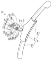
以下、添付図面を参照しながら本発明の実施形態について詳述する。図1は、本発明の実施形態に係る自動車用衣類掛けハンガー10の斜視図であり、図2は、自動車用衣類掛けハンガー10の分解斜視図である。図3は、自動車用衣類掛けハンガー10におけるフック13の構造図であり、図3(a)は、フック13の側面図である。また、図3(b)は、フック13のA−A断面図であり、図3(c)は、フック13のB−B断面図である。図4は、自動車用衣類掛けハンガー10の姿勢を示す断面図であり、図4(a)は、自動車用衣類掛けハンガー10のハンガー本体11が、略鉛直下向き方向に垂下する使用姿勢にある状態を示している。また、図4(b)は、自動車用衣類掛けハンガー10のハンガー本体11が、自動車の天井に沿ってアシストグリップ1の上方に収納される収納姿勢にある状態を示している。
【0020】
まず図1、図2、図4を参照して、図示の実施形態に係る自動車用衣類掛けハンガー10は、自動車室内のアシストグリップ1(図4)に適用される自動車用衣類掛けハンガーであって、頂部にフック13が連結されたハンガー本体11と、フック先端13aを係止可能なフック保持部12とを備えている。フック保持部12には、アシストグリップ1に着脱自在に係止可能なクランプ14が連設されている。また、ハンガー本体11には、フック保持部12に対してハンガー本体11を姿勢変更可能に保持させるための姿勢保持手段20(図1)と、ハンガー本体11の姿勢変更を許容しながら、フック先端13aを係脱可能なロック手段30(図1)とが設けられている。
【0021】
上記ハンガー本体11は、一対のアーム部11aとアーム収納部11bとを有している。
【0022】
この一対のアーム部11aは、衣類の肩から腕にかけての部分を支持するために設けられ、先端が衣類の肩の線に沿って曲面に形成された棒状の樹脂製の部材であり、軽量化のために、下向きに開口した鞘状に形成されている。
【0023】
また、アーム収納部11bは、衣類の衿から肩にかけての部分を支持するとともに、上記一対のアーム部11aをそれぞれ、その内部に収納するために設けられた左右に開口する筒状の樹脂製部材であり、アーム部11aをそれぞれ、ハンガー本体11の中心に向かって前後に重なるようにその内部に引き込んで収納することにより、全体としてハンガー本体11を元の長さの概ね3分の1の長さに縮めてハンガー本体11の収納効率を向上させることができるように構成されている。
【0024】
上記フック保持部12は、フック先端13aを保持するために設けられた輪帯状の樹脂製部材であり、フック先端13aを係脱可能に挿通させるための略水平の左右方向に開口するフック挿通孔12aを有している。
【0025】
このフック挿通孔12aには、内周面に周方向に定ピッチで設けられる断面波型の波型部12bが設けられており、フック先端13aに設けられた後述する突起部13d(図2)が、この波型部12bの谷部に弾性的に嵌合するように構成されている。
【0026】
上記フック13は、ハンガー本体11をハンドリングするとともに、上記フック保持部12に係脱するためにハンガー本体11の頂部に連結される湾曲した合成樹脂製の部材であり、図3を参照して、上部のフック先端13aにフック保持部12に係脱するための抜け止め突起13bおよび抜け止め空隙13cと、ハンガー本体11をフック保持部12に対して姿勢保持するための突起部13d、突起部空隙13eと、下部にハンガー本体11を連結するためのハンガー係止部13gとを有している。
【0027】
この抜け止め突起13bは、フック保持部12(図1)に対してフック先端13aを係脱可能にするために、上記フック先端13aの外周面に設けられた上下一対の突起であり、図1に示すように、フック挿通孔12aの挿入側と反対の外縁部12cの周方向に沿ってガイドされるように設けられているため、フック保持部12に対するハンガー本体11の姿勢変更を許容することができるようになっている。
【0028】
抜け止め空隙13cは、上記抜け止め突起13bを弾性的に変位可能にするために、抜け止め突起13b近傍のフック先端13aの部材に設けられた上下一対の空隙であり、フック先端の側面において水平に貫通して開口するように設けられている。そして、所定値以上の外力が抜け止め突起13bに働くことにより、抜け止め突起13bが、フック保持部12の外縁部12cに対して弾性的に係脱することができるようになっている。
【0029】
ここで、所定値の外力とは、衣類を掛けた状態における通常の取り扱いで抜け止め突起13bに働く外力よりも大きく、フック先端13aをフック保持部12から取り外す必要がある時に人の手で容易に引き抜ける程度の大きさの外力を意味する。
【0030】
また、突起部13dは、ハンガー本体11を、略鉛直下向き方向に垂下する使用姿勢と、自動車の天井に沿ってアシストグリップ1の上方に収納する収納姿勢との間でフック保持部12に対して姿勢変更可能に保持するために、フック挿通孔12aの内周面に設けられる波型部12bの谷部に嵌合するようにフック先端13aに設けられた上下一対の突起であり、この突起部13dと波型部12bの谷部とが弾性的に嵌合位置変更可能な状態で嵌合している。
【0031】
突起部空隙13eは、突起部13dを弾性的に変位可能にするために、突起部13d近傍のフック先端13aの部材に設けられた空隙であり、フック先端13aの側面において水平に貫通して開口するように設けられ、フック先端13aを形成する材料がこの突起部空隙13eの方向へ変形する際に発生する弾性力により、波型部12bの谷部と突起部13dとを、弾性的に嵌合させている。
【0032】
そして、この突起部13dに所定値以上の回動力が働くことにより、突起部13dと波型部12bの谷部とが弾性的に嵌合変更されるようになっている。
【0033】
ここで、所定値の外力とは、自動車の天井に沿ってアシストグリップ1の上方に収納する収納姿勢で、フック保持部12に対するハンガー本体11の姿勢を維持することができる外力よりも大きく、ハンガー本体11の姿勢を変更する必要がある時には、人の手で容易に姿勢変更可能な大きさの外力を意味する。
【0034】
ハンガー係止部13gは、ハンガー本体11のアーム収納部11bに設けられた係止孔11c(図1)と係合してフック13の下部にハンガー本体11を連結するために設けられた断面鉤状の部分であり、フック下部に切込み13hを設けることにより、係止孔11cに対して弾性的に係止され、衣類の重量程度の外力ではフック13からハンガー本体11が抜け落ちないように構成されている。
【0035】
次に図1、図2、図4を参照して、上記クランプ14は、自動車用衣類掛けハンガー10全体をアシストグリップ1に着脱自在に固定するためにフック保持部12に連設された樹脂製の部材であり、一つのクランプピン14aと、一対のクランプ片14bとを有している。
【0036】
このクランプ14に設けられた一対のクランプ片14bは、クランプピン14aを軸として揺動可能に設けられており、それぞれ協働してアシストグリップ1を挟持することができるように、アシストグリップ1に当接する面には、凹凸状の滑り止め14cが形成されている。また、両クランプ片14bの他端には、硬質樹脂製のボルトナット機構14dが設けられ、ナット部14eに固定ボルト14fを締め込むことにより、両クランプ片14bの他端を締結してクランプ14をアシストグリップ1に確実に固定することができるようになっている。
【0037】
上記姿勢保持手段20は、図4を参照して、ハンガー本体11を、略鉛直下向き方向に垂下する使用姿勢と、自動車の天井に沿ってアシストグリップ1の上方に収納する収納姿勢との間でフック保持部12に対して姿勢変更可能に保持するために、フック挿通孔12aの内周面に設けられた複数の内周面凹凸部20aと、上記フック先端13aの外周面に設けられ、任意の内周面凹凸部20aと嵌合可能な複数の外周面凹凸部20bとを備え、両凹凸部20a、20bの嵌合が、弾性的に嵌合位置変更可能となるように設けられた機構である。
【0038】
この姿勢保持手段20は、本実施形態では、前述のように、フック挿通孔12aの内周面に設けられ、周方向に定ピッチで設けられる断面波型の波型部12b(内周面凹凸部20a)と、上記フック先端13aの外周面に設けられ、波型部12bの谷部に嵌合する突起部13d(外周面凹凸部20b)とを備え、この波型部12bの谷部と突起部13dとの嵌合により、上記内周面凹凸部20aと外周面凹凸部20bとの嵌合を形成して上記姿勢保持手段20を構成している。
【0039】
上記ロック手段30は、図1、図2を参照して、フック保持部12とフック先端13aとの間に設けられ、フック保持部12に対するハンガー本体11の姿勢変更を許容しながら、フック挿通孔12aに対してフック先端13aを係脱可能にする機構である。このロック手段30は、本実施形態では、フック先端13aの外周面に設けられ、フック挿通孔12aの挿入側と反対の外縁部12cの周方向に沿ってガイドされる抜け止め突起13bを備え、この抜け止め突起13bに所定値以上の外力が働くことにより、弾性的に外縁部12cに対して抜け止め突起13bが、係脱可能になるように、構成されている。
【0040】
ここで、上記姿勢保持手段20と上記ロック手段30とは、フック先端13aの内部に設けられた空隙部(抜け止め空隙13cと突起部空隙13e)を備えており、フック先端13aを形成する材料がこの空隙部の方向へ変形する際に発生する弾性力により、波型部12bの谷部と突起部13dとの嵌合が、弾性的に嵌合位置変更可能となっている。また、同様にフック先端13aの外周面に設けられた抜け止め突起13bが、外縁部12cに対して弾性的に係脱可能となっている。
【0041】
さらに、フック先端13aの内部には、抜け止め空隙13cと、突起部空隙13eとが開口する両側面において、フック13の長手方向概ね全体にわたって一対の溝部13fが設けられており、突起部13dと抜け止め突起13とにおいて、それぞれの部位の弾力性を増加させている。
【0042】
次に図2、図4を参照して本実施形態の作用について説明する。
【0043】
まず、図2を参照して、フック先端13aをフック挿通孔12aに挿入させる際の各部の作用は以下の通りである。すなわち、抜け止め突起13bがフック挿通孔12aの挿入側外縁12dに当接した状態においてフック13に所定値以上の外力が加わると、フック先端13aを形成する材料が抜け止め空隙13cと突起部空隙13eの方向へそれぞれ変位し、フック先端13aに設けられた抜け止め突起13bと突起部13dとが、空隙の方向に変位して、波型部12bの谷部にガイドされながら挿入される。
【0044】
そして、フック先端13aがフック挿通孔12aを通過すると、抜け止め突起13bが、フック挿通孔12aの挿入側と反対側の外縁12cに係止され、フック先端13aのフック挿通孔12aに対する装着が完了する。
【0045】
次に、図4を参照して、図4(a)は、自動車用衣類掛けハンガー10のハンガー本体11が、略鉛直下向き方向に垂下する使用姿勢にある状態を示している。この状態では、フック先端13aに設けられた上下一対の突起部13dが、フック挿通孔12aの内周面に設けられる波型部12bの谷部に嵌合しているので、ハンガー本体11が、自動車の揺れなどによって容易に揺動しないように姿勢保持されている。
【0046】
また、図4(b)は、波型部12bの谷部と突起部13dとの嵌合が弾性的に変更された結果、ハンガー本体11が、自動車の天井に沿ってアシストグリップ1の上方に収納する収納姿勢になった状態を示している。そして、必要な時には、ハンガー本体11を引き下げることにより、再びワンタッチで衣類を掛けられる使用姿勢にすることができる。
【0047】
以上説明したように、本実施形態によれば、ハンガー本体11を、略鉛直下向き方向に垂下する使用姿勢と、自動車の天井に沿ってアシストグリップ1の上方に収納する収納姿勢との間で姿勢変更可能に保持する姿勢保持手段20を備えているので、ハンガー本体11を使用しない場合は、ワンタッチでアシストグリップ1上方の天井に沿った位置に収納することができる結果、ハンガー本体11をアシストグリップ1に取り付けたままにしておいても窓からの視界を遮ることがない。必要な時には、ハンガー本体11を、使用姿勢にすることにより、ワンタッチで衣類を掛ける状態にすることができる。
【0048】
特に、本実施形態の場合、波型部12bの谷部と突起部13dとの嵌合により、姿勢保持手段20の内周面凹凸部20aと外周面凹凸部20bとの嵌合が形成されているので、よりきめ細かくハンガー本体11の姿勢を選択できる結果、ハンガー本体11の収納効率を向上させることができるように構成されている。
【0049】
また、フック挿通孔12aの内周面凹凸部20a(波型部12bの谷部)とフック先端13aの外周面凹凸部20b(突起部13d)との嵌合が、弾性的に嵌合位置変更可能であるので、ハンガー本体11の姿勢を選択できる結果、異なる車種においても自動車の天井に沿う位置にハンガー本体11を収納することができるなど、ハンガー本体11の収納効率が良く、また車内のスペースを不必要に狭めることがない。
【0050】
さらに、本実施形態によれば、ロック手段30において抜け止め突起13bが、当該外縁部12cの周方向に沿ってガイドされるとともに、所定値以上の外力が働くことにより、弾性的に外縁部12cに対して係脱可能であるので、フック保持部12に対するハンガー本体11の姿勢変更を妨げることがなく、フック挿通孔12aに対してフック先端13aを係脱することができる。その結果、ハンガー本体11がどの姿勢にあってもフック先端13aをフック挿通孔12aに係脱させることができる結果、収納状態にあるハンガー本体11をフック保持部から取り外して、車内のスペースを広く使うことができるだけでなく、ハンガー本体11に衣類を掛けたままの状態でフック先端13aをフック保持部12から取り外すことも可能である。
【0051】
また、衣類をハンガー本体11に掛けたままの状態で通常の家庭用ハンガーのようにフック先端13aを手に掛けて移動することが可能であるなど、極めてハンドリングが容易である。
【0052】
なお、本実施形態によれば、上記フック先端13aの内部に設けられた空隙部(抜け止め空隙13cと突起部空隙13e)という簡単な構成により、波型部12bの谷部と突起部13dとの嵌合を、弾性的に嵌合位置変更可能なものにすることができるだけでなく、抜け止め突起13bを、当該外縁部12cに対して弾性的に係脱可能にすることができる結果、軽量かつシンプルで安価な自動車用衣類掛けハンガーを実現することができる。
【0053】
上述した実施の形態は本発明の好ましい具体例を例示したものに過ぎず、本発明は上述した実施の形態に限定されない。
【0054】
例えば、姿勢保持手段20は、必ずしも図示の実施形態のように、フック挿通孔12aの内周面に波型部12bを備えたものである必要はなく、フック先端13aの外周面に周方向に定ピッチで設けられる断面波型の波型部を設け、フック挿通孔の内周面に上記波型部の山部に嵌合する溝を設けて内周面凹凸部20aと外周面凹凸部20bとの嵌合を形成してもよい。また、フック先端13aに設けた波型部の谷部とフック挿通孔12a側の突起部との嵌合により、上記内周面凹凸部20aと外周面凹凸部20bとの嵌合を形成することも差し支えない。
【0055】
また、ロック手段30としては、必ずしも図示の実施形態に限らず、フック保持部12に対するハンガー本体11の姿勢変更を許容しながら、フック挿通孔12aに対してフック先端13aを係脱可能なロック手段であれば、種々の設計変更が可能である。
【0056】
その他、本発明の特許請求の範囲内で種々の設計変更が可能であることはいうまでもない。
【0057】
【発明の効果】
以上説明したように、本発明によれば、ハンガー本体が使用状態と収納状態との間で姿勢変更可能であるだけでなく、衣類を掛けたままの状態でも着脱可能であるなど、アシストグリップからのハンガー本体の着脱が容易であり、さらに、アシストグリップから取り外した後、通常の家庭用ハンガーのようにハンガー本体のフック部を手に掛けて移動することが可能であるなど、軽量かつシンプルでハンドリングが容易な自動車用衣類掛けハンガーを低コストで実現することができるという顕著な効果を奏する。特にフック先端とフック保持部との間に、ロック手段と、姿勢保持手段とを備えたので、軽量かつシンプルで部品点数が少なく、コンパクトで車内のように狭い場所でもスペースをとらない安価な自動車用衣類掛けハンガーを実現することができる。
【図面の簡単な説明】
【図1】 本発明の実施形態に係る自動車用衣類掛けハンガーの斜視図である。
【図2】 自動車用衣類掛けハンガーの分解斜視図である。
【図3】 自動車用衣類掛けハンガーにおけるフックの構造図であり、(a)は、フックの側面図である。また、(b)は、フックのA−A断面図であり、(c)は、フックのB−B断面図である。
【図4】 自動車用衣類掛けハンガーの姿勢を示す断面図であり、(a)は、自動車用衣類掛けハンガーのハンガー本体が、略鉛直下向き方向に垂下する使用姿勢にある状態を示している。また、(b)は、自動車用衣類掛けハンガーのハンガー本体が、自動車の天井に沿ってアシストグリップの上方に収納される収納姿勢にある状態を示している。
【符号の説明】
1 アシストグリップ
10 自動車用衣類掛けハンガー
11 ハンガー本体
12 フック保持部
12a フック挿通孔
12b 波型部(姿勢保持手段の内周面凹凸部)
12c 外縁部
13 フック
13a フック先端
13b 抜け止め突起(ロック手段)
13c 抜け止め空隙(ロック手段の空隙部)
13d 突起部(姿勢保持手段の外周面凹凸部)
13e 突起部空隙(姿勢保持手段の空隙部)
14 クランプ
20 姿勢保持手段
20a 内周面凹凸部
20b 外周面凹凸部
30 ロック手段[0001]
BACKGROUND OF THE INVENTION
The present invention relates to an automobile clothes hanger applied to an assist grip in an automobile interior.
[0002]
[Prior art]
In an automobile, for example, a clothes hanger for automobiles may be used to hang a jacket that has been taken off. Such a clothes hanger for automobiles is generally a hanger holder that can be attached to and detached from an assist grip (atray grip) on the inner wall of the automobile or the upper surface of a rear seat in the automobile, and a hanger body that is connected to the hanger holder. And a posture holding means for holding the hanger holder so that the posture can be changed between a use posture in which the hanger body is suspended in a substantially vertical downward direction and a storage posture in which the hanger body is stored above the assist grip along the ceiling of the vehicle. It is common to have
[0003]
For example, Japanese Utility Model Publication No. 50-30745 discloses a technique of a clothes hanger for automobiles in which a hanger body is configured to be rotatable between a vertical use posture and a horizontal storage posture. Japanese Patent Application Laid-Open No. 08-056808 discloses a hanger body, a hook member to which the hanger body is rotatably connected, and a biasing force that biases the hanger body in a direction in which the hanger body is turned from the use posture to the storage posture. And a stopper mechanism for temporarily stopping the rotation of the hanger body at a position during the change of the hanger body, suppressing the spring-up of the hanger body when clothes are removed, A hanger technique that reduces the risk of contact with the like is disclosed.
[0004]
[Problems to be solved by the invention]
However, in the prior arts disclosed in these publications, the hanger body cannot be easily removed from the in-vehicle state (utility model publication No. 50-30745) or the hanger body is removed from the assist grip. Even if it is possible, the mechanism of the top of the hanger body becomes complicated because the top of the hanger is accompanied by a mechanism such as a biasing member and a stopper mechanism (Japanese Patent Laid-Open No. 08-056808). There is a problem that handling of the hanger body is not easy, such as being unable to move by holding the top with a hand like a normal household hanger with the hung.
[0005]
In addition, the complexity of the mechanism of the top of the hanger body, such as the biasing member and the stopper mechanism, has increased the cost for manufacturing the hanger.
[0006]
The present invention has been made in view of the above-mentioned problems, and not only the hanger body can be changed in posture between the use state and the storage state, but also can be detachable even while the clothes are worn. It is easy to attach and detach the hanger body from the grip, and after removing it from the assist grip, it can be moved with the hook tip of the hanger body on your hand like a normal household hanger. The object is to provide a simple and easy-to-handle clothes hanger for automobiles at low cost.
[0007]
[Means for Solving the Problems]
In order to solve the above-described problems, the present invention provides a clothes hanger for automobiles applied to an assist grip in an automobile interior, and a hanger body having a hook connected to the top and a hook end inserted in a lockable manner. A hook holding portion having a hook insertion hole that opens in a substantially horizontal direction,Provided between the hook holding portion and the hook tip, and provided between the hook holding portion and the hook tip to enable the hook tip to be engaged and disengaged with respect to the hook insertion hole. A posture holding means for holding the hook holding portion so that the posture can be changed between a use posture hanging in the direction and a storage posture stored above the assist grip along the ceiling of the vehicle;A clamp that is connected to the hook holding portion and can be detachably locked to the assist grip;The locking means includes a retaining protrusion provided on an outer peripheral surface of the hook tip and guided along a circumferential direction of an outer edge opposite to the insertion side of the hook insertion hole, and the retaining protrusion is not less than a predetermined value. When the external force acts, it can be elastically engaged with and disengaged from the outer edge portion, and the posture holding means is provided on either the inner peripheral surface of the hook insertion hole or the outer peripheral surface of the hook tip. A corrugated section of a corrugated section provided at a constant pitch in the circumferential direction, and a protrusion provided on the other, a groove section fitted into a peak section of the corrugated section or a trough section of the corrugated section. The fitting of these two wave-shaped parts can be elastically changed in the fitting position in a state where a turning force of a predetermined value or more acts on the hook tip with respect to the hook insertion hole, and the locking means and the posture The holding means includes a gap provided inside the tip of the hook. Due to the elastic force generated when the material forming the hook tip is deformed in the direction of the gap, the fitting between the crest and groove of the corrugated part or the trough and protrusion of the corrugated part is elastically performed. The fitting position can be changed, and the retaining protrusion provided on the outer peripheral surface of the hook tip can be elastically engaged with and disengaged from the outer edge portion.This is a clothes hanger for automobiles.
[0008]
According to this invention, the posture holding means for holding the hanger body so that the posture can be changed between a use posture in which the hanger body is suspended in a substantially vertical downward direction and a storage posture in which the hanger body is stored above the assist grip along the ceiling of the automobile. , Since it is provided between the hook holding part and the hook tip, when the hanger body is not used, it can be stored in a position along the ceiling above the assist grip with one touch, so the hanger body is attached to the assist grip Even if left untouched, the view from the window is not obstructed. When necessary, the hanger body can be put in a use posture so that clothes can be put on with one touch.
[0009]
In addition, a locking means is provided between the hook holding part and the hook tip so that the hook tip can be engaged with and disengaged from the hook insertion hole, so that the hanger body can be clamped regardless of the posture of the hanger body. As a result of being able to be engaged and disengaged, if not necessary, the hanger body in the stored state can be removed from the clamp, allowing not only wide use of the space in the car, but also the hook tip with the clothes hanging on the hanger body It is also possible to remove from the hook holding part.
[0010]
In addition, after removing the hook tip from the hook insertion hole with the clothes hung on the hanger body, it is possible to hang and move the hook tip like a normal household hanger. Is easy.
[0012]
Also,According to this aspect, the retaining protrusion is guided along the circumferential direction of the outer edge portion, and can be elastically engaged with and disengaged from the outer edge portion by applying an external force of a predetermined value or more. The hook can be inserted into and removed from the hook insertion hole regardless of the posture of the main body.
[0013]
Further, the posture holding means is provided on the inner peripheral surface uneven portion provided on the inner peripheral surface of the hook insertion hole and on the outer peripheral surface of the hook tip, and can be fitted to any inner peripheral surface uneven portion. A plurality of concavo-convex parts on the outer peripheral surface, and the fitting of both the concavo-convex parts can be elastically changed in the fitting position with a turning force of a predetermined value or more acting on the hook tip with respect to the hook insertion hole. It is preferable.
[0016]
Also,The crest and groove of the corrugated part or the trough and corrugated part of the corrugated partThe fitting position can be changed elastically with the turning force exceeding the predetermined value applied to the hook insertion hole, and the attitude of the hanger body can be finely selected. The storage efficiency of the hanger body can be improved, for example, the hanger body can be stored at a position along the hanger. Moreover, the space in the vehicle is not unnecessarily narrowed.
[0018]
AndWith the simple configuration of the gap provided inside the hook tip, the fitting position of the crest and groove of the corrugated part or the trough and corrugated part of the corrugated part can be changed elastically. As a result, it is possible to realize a lightweight, simple, and inexpensive clothes hanger for automobiles. .
[0019]
DETAILED DESCRIPTION OF THE INVENTION
Hereinafter, embodiments of the present invention will be described in detail with reference to the accompanying drawings. FIG. 1 is a perspective view of an
[0020]
First, referring to FIGS. 1, 2, and 4, an
[0021]
The
[0022]
The pair of
[0023]
The
[0024]
The
[0025]
This
[0026]
The
[0027]
The retaining
[0028]
The retaining
[0029]
Here, the external force of the predetermined value is larger than the external force that acts on the retaining
[0030]
Further, the protruding
[0031]
The
[0032]
Then, when a turning force of a predetermined value or more is applied to the protruding
[0033]
Here, the external force having a predetermined value is a storage posture in which the external grip is stored above the assist grip 1 along the ceiling of the automobile, and is larger than the external force capable of maintaining the posture of the
[0034]
The
[0035]
Next, referring to FIGS. 1, 2, and 4, the
[0036]
The pair of
[0037]
With reference to FIG. 4, the posture holding means 20 is between a usage posture in which the
[0038]
In the present embodiment, as described above, the posture holding means 20 is provided on the inner peripheral surface of the
[0039]
1 and 2, the locking means 30 is provided between the
[0040]
Here, the posture holding means 20 and the locking means 30 are provided with gaps (a retaining
[0041]
Furthermore, a pair of
[0042]
Next, the operation of this embodiment will be described with reference to FIGS.
[0043]
First, referring to FIG. 2, the operation of each part when the
[0044]
When the
[0045]
Next, referring to FIG. 4, FIG. 4 (a) shows a state where the
[0046]
Further, FIG. 4B shows that the
[0047]
As described above, according to the present embodiment, the
[0048]
Particularly, in the case of this embodiment, the fitting between the inner peripheral surface
[0049]
Further, the fitting between the inner peripheral surface
[0050]
Furthermore, according to the present embodiment, the retaining
[0051]
In addition, handling is extremely easy because the
[0052]
Note that, according to the present embodiment, the trough portion of the
[0053]
The above-described embodiment is merely a preferred specific example of the present invention, and the present invention is not limited to the above-described embodiment.
[0054]
For example, the posture holding means 20 does not necessarily have to have the corrugated
[0055]
Further, the locking means 30 is not necessarily limited to the illustrated embodiment, and the locking means is capable of engaging and disengaging the
[0056]
In addition, it goes without saying that various design changes are possible within the scope of the claims of the present invention.
[0057]
【The invention's effect】
As described above, according to the present invention, the hanger body is not only capable of changing the posture between the use state and the storage state, but also can be attached and detached while the clothes are hung, etc. It is easy to attach and detach the hanger body, and after removing it from the assist grip, it can be moved by hooking the hook part of the hanger body like a normal household hanger, and it is lightweight and simple. There is a remarkable effect that an easy-to-handle automobile clothes hanger can be realized at low cost.In particular, because it has locking means and posture holding means between the hook tip and the hook holding part, it is lightweight and simple, has a small number of parts, is compact, and does not take up space even in a confined space such as in a car. A clothes hanger for clothing can be realized.
[Brief description of the drawings]
FIG. 1 is a perspective view of an automobile clothes hanger according to an embodiment of the present invention.
FIG. 2 is an exploded perspective view of a clothes hanger for automobiles.
FIG. 3 is a structural view of a hook in a clothes hanger for automobiles, and (a) is a side view of the hook. Moreover, (b) is AA sectional drawing of a hook, (c) is BB sectional drawing of a hook.
FIG. 4 is a cross-sectional view showing the posture of an automobile clothes hanger. FIG. 4 (a) shows a state in which the hanger body of the automobile clothes hanger is in a use posture in which it hangs down substantially vertically downward. Moreover, (b) has shown the state which has the accommodation attitude | position in which the hanger main body of the clothes hanger for motor vehicles is stored above an assist grip along the ceiling of a motor vehicle.
[Explanation of symbols]
1 Assist grip
10 Car clothes hanger
11 Hanger body
12 Hook holder
12a Hook insertion hole
12b Corrugated part (inner peripheral surface uneven part of posture holding means)
12c outer edge
13 hook
13a Hook tip
13b Retaining protrusion (locking means)
13c Cavity gap (gap of lock means)
13d Protrusion (outer peripheral surface uneven portion of the posture holding means)
13e Protruding part gap (gap part of posture holding means)
14 Clamp
20 Posture holding means
20a Uneven part of inner peripheral surface
20b Uneven surface on outer peripheral surface
30 Locking means
Claims (1)
頂部にフックが連結されたハンガー本体と、
フック先端を係止可能に挿通させるために略水平方向に開口するフック挿通孔を有するフック保持部と、
フック保持部とフック先端との間に設けられ、フック挿通孔に対してフック先端を係脱可能とするロック手段と
フック保持部とフック先端との間に設けられ、ハンガー本体を、略鉛直下向き方向に垂下する使用姿勢と、自動車の天井に沿ってアシストグリップの上方に収納する収納姿勢との間でフック保持部に対して姿勢変更可能に保持する姿勢保持手段と、
フック保持部に連設され、アシストグリップに着脱自在に係止可能なクランプと、
を備え、
上記ロック手段は、上記フック先端の外周面に設けられ、上記フック挿通孔の挿入側と反対の外縁部周方向に沿ってガイドされる抜け止め突起を備え、この抜け止め突起は、所定値以上の外力が働くことにより、弾性的に上記外縁部に対して係脱可能であり、
上記姿勢保持手段は、上記フック挿通孔の内周面か、上記フック先端の外周面のいずれかに設けられ、周方向に定ピッチで設けられる断面波型の波型部と、他方に設けられ、上記波型部の山部に嵌合する溝部もしくは波型部の谷部に嵌合する突起部とを備え、これら両波型部の嵌合は、フック挿通孔に対して所定値以上の回動力がフック先端に働いた状態で弾性的に嵌合位置変更可能であり、
上記ロック手段と、上記姿勢保持手段は、上記フック先端の内部に設けられた空隙部を備え、フック先端を形成する材料がこの空隙部の方向へ変形する際に発生する弾性力により、波型部の山部と溝部もしくは波型部の谷部と突起部との嵌合が、弾性的に嵌合位置変更可能であるとともに、フック先端の外周面に設けられた抜け止め突起が、当該外縁部に対して弾性的に係脱可能である
ことを特徴とする自動車用衣類掛けハンガー。A clothes hanger for automobiles applied to an assist grip in an automobile interior,
A hanger body with a hook connected to the top,
A hook holding portion having a hook insertion hole that opens in a substantially horizontal direction to allow the hook tip to be inserted in a lockable manner;
A locking means provided between the hook holding portion and the hook tip, and capable of engaging and disengaging the hook tip with respect to the hook insertion hole;
Provided between the hook holding part and the hook tip, the hook holding part between a use posture in which the hanger body is suspended in a substantially vertical downward direction and a storage posture in which the hanger body is stored above the assist grip along the ceiling of the automobile. Posture holding means for holding the posture changeable with respect to,
A clamp that is connected to the hook holding portion and can be detachably locked to the assist grip;
With
The locking means includes a retaining protrusion provided on an outer peripheral surface of the hook tip and guided along a circumferential direction of an outer edge opposite to the insertion side of the hook insertion hole, and the retaining protrusion is equal to or greater than a predetermined value. When the external force is applied, it can be elastically engaged with and disengaged from the outer edge portion.
The posture holding means is provided on either the inner peripheral surface of the hook insertion hole or the outer peripheral surface of the hook tip, and is provided on the other side of the corrugated section having a cross-sectional corrugated shape provided at a constant pitch in the circumferential direction. A groove portion that fits into the crest portion of the corrugated portion or a projection portion that fits into the trough portion of the corrugated portion, and the fitting of both the corrugated portions is a predetermined value or more with respect to the hook insertion hole. The fitting position can be changed elastically with the rotational force acting on the tip of the hook,
The locking means and the posture holding means include a gap provided inside the tip of the hook, and corrugated by the elastic force generated when the material forming the hook tip is deformed in the direction of the gap. The fitting between the crest and groove of the ridge or the trough and projection of the corrugated part can be changed elastically, and the retaining protrusion provided on the outer peripheral surface of the hook tip is connected to the outer edge. A clothes hanger for automobiles that is elastically detachable with respect to a part .
Priority Applications (1)
| Application Number | Priority Date | Filing Date | Title |
|---|---|---|---|
| JP2001346605A JP3980329B2 (en) | 2001-11-12 | 2001-11-12 | Clothes hanger for automobile |
Applications Claiming Priority (1)
| Application Number | Priority Date | Filing Date | Title |
|---|---|---|---|
| JP2001346605A JP3980329B2 (en) | 2001-11-12 | 2001-11-12 | Clothes hanger for automobile |
Publications (2)
| Publication Number | Publication Date |
|---|---|
| JP2003146143A JP2003146143A (en) | 2003-05-21 |
| JP3980329B2 true JP3980329B2 (en) | 2007-09-26 |
Family
ID=19159755
Family Applications (1)
| Application Number | Title | Priority Date | Filing Date |
|---|---|---|---|
| JP2001346605A Expired - Lifetime JP3980329B2 (en) | 2001-11-12 | 2001-11-12 | Clothes hanger for automobile |
Country Status (1)
| Country | Link |
|---|---|
| JP (1) | JP3980329B2 (en) |
Families Citing this family (1)
| Publication number | Priority date | Publication date | Assignee | Title |
|---|---|---|---|---|
| KR100908476B1 (en) * | 2007-05-21 | 2009-07-21 | 오창춘 | Hanger Hanging on Handle of Car |
-
2001
- 2001-11-12 JP JP2001346605A patent/JP3980329B2/en not_active Expired - Lifetime
Also Published As
| Publication number | Publication date |
|---|---|
| JP2003146143A (en) | 2003-05-21 |
Similar Documents
| Publication | Publication Date | Title |
|---|---|---|
| US5509182A (en) | Clip for attaching sheet material to a body panel | |
| US5625921A (en) | Combined assist handle and hanger support | |
| US6961978B2 (en) | Detachable handle assembly for rolling luggage | |
| US6698966B2 (en) | Fastenings | |
| JP3301255B2 (en) | Vehicle trunk net layout structure | |
| US5524857A (en) | Multi use flag holder apparatus | |
| JP3980329B2 (en) | Clothes hanger for automobile | |
| US20060243764A1 (en) | Hanger assembly for vehicle use | |
| JP2001171438A (en) | Mounting device for parts of automobile | |
| JP2524211Y2 (en) | Synthetic resin cable support | |
| JP3496817B2 (en) | Hanging equipment | |
| KR200335645Y1 (en) | subsidiary handle for a car | |
| JPH0637205Y2 (en) | Car trim retainer | |
| JPS641912Y2 (en) | ||
| AU738249B2 (en) | Improvements in fastenings | |
| JP3641404B2 (en) | Hanging tool | |
| JPH0750282Y2 (en) | Strap hanger mounting structure | |
| JP2599199Y2 (en) | Futon shears | |
| JP2000153739A (en) | Simple garbage bag holder for vehicle | |
| KR950006010Y1 (en) | Holding appliance inside of vehicle for supporting clothes | |
| JPH0432949Y2 (en) | ||
| JP3033493U (en) | Hanger | |
| JPH0437155Y2 (en) | ||
| JP2579394Y2 (en) | hook | |
| JPH0346954Y2 (en) |
Legal Events
| Date | Code | Title | Description |
|---|---|---|---|
| A621 | Written request for application examination |
Free format text: JAPANESE INTERMEDIATE CODE: A621 Effective date: 20041004 |
|
| A977 | Report on retrieval |
Free format text: JAPANESE INTERMEDIATE CODE: A971007 Effective date: 20060929 |
|
| A131 | Notification of reasons for refusal |
Free format text: JAPANESE INTERMEDIATE CODE: A131 Effective date: 20070130 |
|
| A521 | Written amendment |
Free format text: JAPANESE INTERMEDIATE CODE: A523 Effective date: 20070402 |
|
| TRDD | Decision of grant or rejection written | ||
| A01 | Written decision to grant a patent or to grant a registration (utility model) |
Free format text: JAPANESE INTERMEDIATE CODE: A01 Effective date: 20070605 |
|
| A61 | First payment of annual fees (during grant procedure) |
Free format text: JAPANESE INTERMEDIATE CODE: A61 Effective date: 20070627 |
|
| R150 | Certificate of patent or registration of utility model |
Free format text: JAPANESE INTERMEDIATE CODE: R150 Ref document number: 3980329 Country of ref document: JP Free format text: JAPANESE INTERMEDIATE CODE: R150 |
|
| FPAY | Renewal fee payment (event date is renewal date of database) |
Free format text: PAYMENT UNTIL: 20100706 Year of fee payment: 3 |
|
| FPAY | Renewal fee payment (event date is renewal date of database) |
Free format text: PAYMENT UNTIL: 20100706 Year of fee payment: 3 |
|
| FPAY | Renewal fee payment (event date is renewal date of database) |
Free format text: PAYMENT UNTIL: 20110706 Year of fee payment: 4 |
|
| R250 | Receipt of annual fees |
Free format text: JAPANESE INTERMEDIATE CODE: R250 |
|
| FPAY | Renewal fee payment (event date is renewal date of database) |
Free format text: PAYMENT UNTIL: 20120706 Year of fee payment: 5 |
|
| R250 | Receipt of annual fees |
Free format text: JAPANESE INTERMEDIATE CODE: R250 |
|
| FPAY | Renewal fee payment (event date is renewal date of database) |
Free format text: PAYMENT UNTIL: 20130706 Year of fee payment: 6 |
|
| R250 | Receipt of annual fees |
Free format text: JAPANESE INTERMEDIATE CODE: R250 |
|
| R250 | Receipt of annual fees |
Free format text: JAPANESE INTERMEDIATE CODE: R250 |
|
| R250 | Receipt of annual fees |
Free format text: JAPANESE INTERMEDIATE CODE: R250 |
|
| R250 | Receipt of annual fees |
Free format text: JAPANESE INTERMEDIATE CODE: R250 |
|
| R250 | Receipt of annual fees |
Free format text: JAPANESE INTERMEDIATE CODE: R250 |
|
| R250 | Receipt of annual fees |
Free format text: JAPANESE INTERMEDIATE CODE: R250 |
|
| R250 | Receipt of annual fees |
Free format text: JAPANESE INTERMEDIATE CODE: R250 |
|
| R250 | Receipt of annual fees |
Free format text: JAPANESE INTERMEDIATE CODE: R250 |
|
| R250 | Receipt of annual fees |
Free format text: JAPANESE INTERMEDIATE CODE: R250 |
|
| R250 | Receipt of annual fees |
Free format text: JAPANESE INTERMEDIATE CODE: R250 |
|
| EXPY | Cancellation because of completion of term |