JP3979570B2 - forklift - Google Patents
forklift Download PDFInfo
- Publication number
- JP3979570B2 JP3979570B2 JP2002035242A JP2002035242A JP3979570B2 JP 3979570 B2 JP3979570 B2 JP 3979570B2 JP 2002035242 A JP2002035242 A JP 2002035242A JP 2002035242 A JP2002035242 A JP 2002035242A JP 3979570 B2 JP3979570 B2 JP 3979570B2
- Authority
- JP
- Japan
- Prior art keywords
- pallet
- fork
- bracket
- lock
- load
- Prior art date
- Legal status (The legal status is an assumption and is not a legal conclusion. Google has not performed a legal analysis and makes no representation as to the accuracy of the status listed.)
- Expired - Fee Related
Links
- 238000006073 displacement reaction Methods 0.000 claims description 4
- 238000005452 bending Methods 0.000 description 2
- 230000000694 effects Effects 0.000 description 2
- 230000003028 elevating effect Effects 0.000 description 2
- 238000003780 insertion Methods 0.000 description 2
- 230000037431 insertion Effects 0.000 description 2
- 230000002452 interceptive effect Effects 0.000 description 2
- 230000001174 ascending effect Effects 0.000 description 1
- 238000009833 condensation Methods 0.000 description 1
- 230000005494 condensation Effects 0.000 description 1
- 238000000034 method Methods 0.000 description 1
- 238000012986 modification Methods 0.000 description 1
- 230000004048 modification Effects 0.000 description 1
- 238000004904 shortening Methods 0.000 description 1
- 229920003002 synthetic resin Polymers 0.000 description 1
- 239000000057 synthetic resin Substances 0.000 description 1
Images


Landscapes
- Forklifts And Lifting Vehicles (AREA)
Description
【0001】
【発明の属する技術分野】
本発明は、フォークにより持ち上げたパレットを、搬送時にパレット上で不測に位置ずれしないようにロックするための、パレットロック装置を備えたフォークリフトに関する。
【0002】
【従来の技術】
リーチ型と称されるフォークリフトの例を図4に示す。これは車体1と、該車体1の前方に突出する左右一対のストラドルレッグ2とからなり、該車体1及びストラドルレッグ2にそれぞれ後輪1aと前輪1bが設けられる。また該ストラドルレッグ2に沿って左右一対のマスト3が車体前後方向に移動可能に設けられ、該マスト3にはリフトブラケット4が昇降可能に配置されると共に、該リフトブラケット4を昇降させるための昇降手段としてのリフトシリンダ5が配設される。更に上記リフトブラケット4には左右一対の側面視L字形のフォーク6が支持され、該フォーク6は上記リフトシリンダ5によって、リフトブラケット4と共に上記マスト3に沿って昇降される。Pは内部に孔Phを有するパレットであり、該孔Ph内に上記フォーク6が挿入されることにより、その上面に載置された荷Wと共にフォーク6によって持ち上げられ搬送される。7は車体後部に配置された運転席であり、上記車体1の走行やリフトシリンダ5の駆動は該運転席に設けられた各種レバー8等をオペレータが操作することにより行われる。なお、上記フォーク6は軸9によって上記リフトブラケット4に対し所定角度内で上下傾動可能となっており、荷WをパレットPと共に搬送するときは、図示しない装置によって上記フォーク6を上方に少し傾動させることにより、該荷Wが荷崩れしにくい状態で行われる。
【0003】
【発明が解決しようとする課題】
上記した従来通常のフォークリフトでは、冷凍庫内など、パレットPに結露が生じやすい場所で搬送作業を行なう場合や、摩擦係数が小さい合成樹脂製のパレットを使用する場合などでは、パレットPがフォーク6上で滑って位置ずれし、荷崩れを起こすことがある。
【0004】
上記したように、フォーク6を少し上方に傾動させることによって荷崩れの可能性は少なくなるが、それでもパレットPのフォーク6上での滑りをなくすことはできず、車体旋回時に荷崩れが発生することは避けられない。また、荷Wを短い距離だけ搬送する場合などは、わざわざこのフォーク傾動を行うことが面倒であるため、フォーク6を水平姿勢としたまま搬送作業を行うことが多く、このような場合は特にパレットPの滑りが発生し易い。
【0005】
本発明は、上記した問題点に鑑み、まず第1に、フォーク上でパレットが滑り、又は位置ずれを生じたり、あるいは揺動したりしないよう、パレットをロックすることにより、荷崩れ等を防止できるようにしたフォークリフトを提供することを目的とする。また本発明は、第2に、フォークを上下に傾動させない状態においても、確実にパレットの滑り等を防止できるフォークリフトを提供することを目的とする。
【0006】
【課題を解決するための手段】
上記目的を達成するため、荷を載置するためのパレットに挿入されるフォーク及び該フォークを支持するためのリフトブラケットを備えた荷支持手段と、該荷支持手段を昇降させるための昇降手段とを有するフォークリフトにおいて、上記荷支持手段に、上記フォークに挿入されたパレットを該パレットの内側下面を押圧することによりロックするパレットロック装置を設け、該パレットロック装置は、上記荷支持手段に固着されたブラケットと、該ブラケットに軸を中心に旋回自在に支持されたロック部材と、上記ブラケットとロ ック部材との間に張設されて該ロック部材を上方に旋回付勢するスプリングとからなり、また該ロック部材は、該スプリングにより上記フォークの上面より突出付勢されると共に上記パレットに対する該フォークの相対的な上昇時に該パレットに押圧され上記スプリングに抗して下方に旋回変位する可動部材と、該可動部材の変位に連動して下方に旋回移動し上記パレットの内側下面を押圧するロックバーとを一体的に備えており、該可動部材が上記パレットにより押圧されて下方に変位した分だけ上記ロックバーが下方に移動することにより、上記可動部材が上記パレットの内側上面を、上記ロックバーが上記パレットの内側下面を、それぞれ押圧することを特徴とするフォークリフトを提供する。
【0007】
この発明によれば、フォークに挿入されたパレットをロックするパレットロック装置を設けると共に、該パレットロック装置を、パレットに対する上記フォークの相対的な上昇に連動して作動させるようにしたので、パレットをフォークで持ち上げる瞬間に該パレットをロックできる。従ってフォークを傾動させない状態でも、フォーク上でパレットが滑り、あるいは揺動することが皆無となる。しかも上記パレットロック装置を、パレットの内側下面即ち下側デッキボードの上面を押圧するものとしたので、パレットの上面即ち上側デッキボードの上面のすべてに荷を載置することが可能となり、多くの荷を積載し搬送することができる。上記パレットロック装置は、フォークの相対的な上昇に機械的に連動して機械的に作動するものが、構成容易で安価であり、故障も少ない、といった点で好ましい。この発明において、荷支持手段とは上記フォーク及びリフトブラケットを総称して示す用語であり、従って上記パレットロック装置は上記フォーク又はリフトブラケットのうち、何れに設けても良い。またこの発明において昇降手段とは例えばマストやリフトシリンダ等をいうものとする。
【0008】
またこの発明によれば、パレットを地面あるいは棚上に載置した瞬間に、パレットのロックが解除されるため、荷卸し作業が極めて容易となる。またロック解除のための特別の手動装置・手動操作を必要としないので、効率的な荷卸し作業を実現できる。
【0009】
更にこの発明によれば、上記パレットロック装置が、フォークの上昇時に上記パレットに接触して変位する可動部材と、該可動部材の変位に連動して該パレットを押圧するロックバーとを備えることとしたので、上記可動部材がパレットに接触することによりフォークの上昇を確実に検出でき、また上記ロックバーの作動タイミングを確実なものとすることができる。即ち、フォークのパレットに対する相対的な上昇が不十分なタイミングでパレットのロックを行えば、該パレットがその瞬間にロック動作に伴って揺動し、荷崩れを起こす可能性があるからである。パレットの大きさや形状は一定でなく、また該パレットに対するフォークの挿入高さ位置も一定ではないため、パレットを揺動させることなくロックするタイミングの設定は困難であるが、本発明によればこのロック動作を好適なタイミングにて実行することができる。
【0010】
また更にこの発明によれば、可動部材とロックバーとが互いに一体に形成されており、一体的に移動するので、極めて簡素な構成で、パレットのロックを確実に行うことができる。またパレットの内側上面即ち上側デッキボードの下面を上記フォークと上記可動部材とにより、パレットの内側下面面即ち下側デッキボードの上面を上記ロックバーにより、それぞれ押圧することによって、パレットを強力に固定できる。
【0011】
上記した本発明は、実施の態様に応じてそれぞれ様々な形態をとることができる。これらの本発明は、その趣旨を逸脱しない限りにおいて、これら形態の全てを包含するものである。しかしなお、本発明に係るフォークリフトにおけるパレットロック装置はパレットの内側下面、即ち下側デッキボードの上面を押圧することにより該パレットをロックするものであり、例えばパレットの上側デッキボードに係合し又はこれを押圧するものではない。本発明は、フォークの上昇動作とパレットロック装置による下方への押圧動作という互いに上下逆方向の動作を行うことにより、パレットをその内側より上下両方向から押圧するものであり、しかもこの上下押圧動作をフォークの上昇動作に連動してほぼ同時に行うものである。従って本発明は、上側デッキボードに接触して該上側デッキボードに係合又は押圧する、あるいは下側デッキボードに接触して該下側デッキボードに係合又は押圧する、といった類のものとはその技術思想が基本的に相違するものであり、更にパレットをフォークで持ち上げた後に手動でロック操作を行う、といった技術とも、明らかに相違するものである。
【0012】
【発明の実施の形態】
本発明に係るリーチ型フォークリフトの全体概要は、既に説明した図4に示すものと基本的に同一である。従って以下の説明において、図4で説明した部材については同一符号を用い、その詳細な説明は省略する。
【0013】
本発明の第1の実施形態について、図1,図2a及び図2bで説明する。図1はフォークリフトを上方から見た概略図を示している(ヘッドガード等は省略してある)。図2aは地面等に接地されたパレットPの孔Phにフォーク6を挿入した状態を示し、図2bは図2aの状態からフォーク6を上昇させた状態を示し、一対のフォーク6をその内側から見たものを示している。円内に拡大して示してある11は左右一対のパレットロック装置であり、各フォーク6のそれぞれ内側に近接させて配設されている。
【0014】
パレットロック装置11はフォーク6の屈曲部分の内側面に固着されたブラケット12と、該ブラケット12に軸13により旋回自在に支持されたロック部材14と、上記ブラケット12とロック部材14との間に張設されたスプリング15とから構成される。上記ブラケット12はその下端がフォーク6よりも車体後方に向けて突出しており、その突出部分に上記軸13が配設される。上記スプリング15はフォーク6の垂直部分に上下方向に設けられ、その上端はブラケット12の上部に固定されたピン16aに、その下端は上記ロック部材14における上記軸13より車体前方寄り位置に固定されたピン16bに、それぞれ係合される。上記ロック部材14は上方に大きく膨らむように略円形に突出した可動部材17の部分と、該可動部材17と一体のロックバー18の部分とから一体的に構成される。ロックバー18は、可動部材17の下側部分からその前方に延びる弾性部材としての板バネ19と、該板バネ19の先端に固定された摩擦部材20とを備えている。摩擦部材20はゴムのように摩擦係数の大きな部材で形成され、あるいは下面に摩擦力を高めるためのギザギザ等が形成されている。
【0015】
ロック部材14は図2aの状態において、上記スプリング15により軸13を中心に図面右回り方向に旋回付勢されて上方に引き上げられ、その上縁が上記ブラケット12に突設されたストッパ21に当接することによって制止されている。この図2aの状態においてロック部材14はその下縁がフォーク6と平行になるよう、また上記可動部材17を除く部分が側面視においてフォーク6の上下範囲内に含まれるように配置される。またこの状態において上記可動部材17はフォーク6の上面より上方に突出し、かつ、この可動部材17を含むロック部材14の全体がその上下にスキマ22a,22bを残してパレットPの孔Ph内に位置できるよう、その上下寸法が設定される。従ってフォーク6をパレットPの孔Ph内に挿入するとき、上記パレットロック装置11は該パレットPと干渉することなく、該孔Ph内に円滑に挿入される。
【0016】
荷取り作業の例について説明すると、パレットPへのフォーク6の挿入が完了し、図2aの状態からフォーク6を上昇させれば、フォーク6とパレットPとの相対的な高さ関係は変化し、上位のスキマ22aは次第に小さく、下位のスキマ22bは次第に大きくなる。上記スキマ22aがゼロとなって可動部材17がパレットPの内側上面、即ち該パレットを構成する上側デッキボードP1の下面に接触すると、該可動部材17が下方に押圧されることによって、ロック部材14はスプリング15の力に抗して軸13を中心に下方に旋回する。フォーク6が上記した上側デッキボードP1の下面に接触する前に、即ち可動部材17がフォーク6の上面まで変位しないうちに、上記摩擦部材20がパレットPの内側下面即ち下側デッキボードP2の上面に接触するよう、上記板バネ19の長さが設定されており、該摩擦部材20が下側デッキボードP2に接触してこれに押圧力を付与した直後に、フォーク6が上側デッキボードP1に接触してこれを押圧する。即ち図2bの状態において、上側デッキボードP1の下面にはフォーク6と共に可動部材17が当接してこれを上方に押圧し、またロックバー18の摩擦部材20が下側デッキボードP2の上面に当接してこれを下方に押圧する。またこのとき板バネ19は少し屈曲して摩擦部材20に押圧力を付与し続ける。また該板バネ19はパレットPの孔Phの上下寸法にバラツキが存在するとき、その屈曲によって上記バラツキを吸収する作用を奏する。
【0017】
これによってパレットPはその内部から上下に押圧力を受けてロックされ、フォーク6から容易に離脱しない状態となる。フォークが更に上昇を続けても図2bに示す状態は維持され、従ってパレットPのフォーク6上での滑りや位置ずれ、揺動等が防止され、該パレットP上での荷Wは荷崩れを生じることなく安定して保持される。
【0018】
フォークリフトによる荷Wの移動搬送を終了して該荷WをパレットPごと別の地面あるいは棚に荷卸しするとき、パレットロック装置11は図2bから図2aへと、上記した荷取りの場合とは逆の動作を行う。つまりパレットPが上記した棚等に当接して下降動作を停止すると、フォーク6の継続的な下降動作によって、該フォーク6はその上面が上側デッキボードP1から離反する。またこれに伴い、ロック部材14もスプリング15の力によって傾斜角度が小さくなるように姿勢が変化し、摩擦部材20が下側デッキボードP2から離れ、図2aに示す元の状態に復帰する。
【0019】
これによりパレットPはロック状態から解放され、更にこの状態からフォーク6を車体後方に向けて移動させることにより、フォーク6がパレットPから離脱して荷卸しが完了する。従って、上記した第1の実施形態によれば、荷取り操作から荷卸し操作に至るまで、パレットPはフォーク6上においてしっかりとロックされ、滑りや揺動を生じることがない。またこの荷取り操作及び荷卸し操作におけるパレットロック動作はオペレータによる手作業を一切必要とせず、またモータやシリンダ装置のような駆動源、あるいは電気的手段をも必要とせず、簡単な機構にて確実に行われる。
【0020】
なお、この第1の実施形態においては、パレットロック装置11をフォーク6に設けるようにしてあるが、これを後述する第2の実施形態のように、リフトブラケット4に設けるようにしても良い。
【0021】
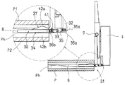
次に、第2の実施形態について図3a及び図3bを用いて説明する。なお、図1はこの第2の実施形態についてもほぼ共通に適用できる。前記した第1の実施形態の場合と同様に、図3aは地面等に接地されたパレットPの孔P1にフォーク6を挿入した状態を示し、図3bは図3aの状態からフォーク6を上昇させた状態を示している。円内に拡大して示してある31は左右一対のパレットロック装置であり、各フォーク6のそれぞれ内側に近接させて配設されている。
【0022】
パレットロック装置31は前記したリフトブラケット4の下部に固着されたブラケット32と、該ブラケット32に軸33により上下旋回自在に支持されたロック部材34と、上記ブラケット32とロック部材34との間に張設されたスプリング35とから構成される。上記ブラケット32はその下端がフォーク6の水平部分と同一高さ位置となるよう、車体前方に向けて屈曲されたL字形をしており、その水平部分に上記軸33が配設される。上記スプリング35はフォーク6の水平部分に沿って略水平方向に設けられ、その後端はブラケット32の屈曲部分に固定されたピン36aに、その先端は上記ロック部材34における上記軸33より車体前方寄り位置に固定されたピン36bに、それぞれ係合される。上記ロック部材34は上方に大きく膨らむように略円形に突出した可動部材37の部分と、該可動部材37と一体のロックバー38の部分とから一体的に構成される。
【0023】
図3aの状態において上記スプリング35は、その中心線35a(即ち両ピン36a,36bを結ぶ直線)が、上記軸33の中心より上方に位置するように設定されている。従ってロック部材34は、上記スプリング35により軸33を中心に図面右回り方向に旋回付勢されて上方に引き上げられ、その上縁が上記ブラケット32に突設されたストッパ41に当接することによって制止されている。この図3aの状態においてロック部材34はその下縁がフォーク6と平行になるよう、また上記可動部材37を除く部分が側面視においてフォーク6の上下範囲内に含まれるように配置される。またこの状態において上記可動部材37はフォーク6の上面より上方に突出し、かつ、この可動部材37を含むロック部材34の全体がその上下にスキマ42a,42bを残してパレットPの孔Ph内に位置できるよう、その上下寸法が設定される。従ってフォーク6をパレットPの孔Ph内に挿入するとき、上記パレットロック装置31は該パレットPと干渉することなく、該孔Ph内に円滑に挿入される。
【0024】
荷取り作業の例について説明すると、パレットPへのフォーク6の挿入が完了し、図3aの状態からフォーク6を上昇させれば、フォーク6とパレットPとの相対的な高さ関係は変化し、上位のスキマ42aは次第に小さく、下位のスキマ42bは次第に大きくなる。上記スキマ42aがゼロとなって可動部材37がパレットPの内側上面、即ち該パレットを構成する上側デッキボードP1の下面に接触すると、該可動部材37が下方に押圧されることによって、ロック部材34はスプリング35の力に抗して軸33を中心に下方に旋回する。ロック部材34の旋回に連れて、上記したスプリング35の中心線35aも車体後方位置のピン36aを中心として下方に旋回する。ロック部材34が所定角度だけ旋回すると上記中心線35aは該ロック部材34の旋回軸33を上から下へと横切り、その下方に位置する。すると、上記スプリング35は該軸33を中心としてロック部材34を下方に付勢するように作用し、即ちその付勢力の方向を上方から下方へと反転させ、これによって該ロック部材34は下方に旋回し、そのロックバー38の先端部がパレットPの内側下面即ち下側デッキボードP2の上面に当接してこれを押圧する。フォーク6が上記した上側デッキボードP1の下面に接触する前に、即ち可動部材37がフォーク6の上面まで変位しないうちに、上記したロック部材34の下方への旋回が行われるよう、パレットロック装置31の各部の寸法及び配置が設定されている。従って、ロックバー38の先端部が下側デッキボードP2の上面に当接してこれに押圧力を付与した直後に、フォーク6が上側デッキボードP1に接触してこれを押圧する。即ち図3bの状態において、上側デッキボードP1の下面にはフォーク6が当接してこれを上方に押圧し、またロックバー38が下側デッキボードP2の上面に当接してこれを下方に押圧する。またこのとき弾性部材としてのスプリング35は、パレットPの孔Phの上下寸法にバラツキが存在するとき、該バラツキを吸収する作用をも奏する。
【0025】
これによってパレットPはその内部から上下に押圧力を受けてロックされ、フォーク6から容易に離脱しない状態となる。フォークが更に上昇を続けても図3bに示す状態は維持され、従ってパレットPのフォーク6上での滑りや位置ずれ、揺動等が防止され、該パレットP上での荷Wは荷崩れを生じることなく安定して保持される。
【0026】
フォークリフトによる荷Wの移動を終了して該荷WをパレットPごと別の地面あるいは棚に荷卸しするとき、パレットロック装置31は図3bから図3aへと、上記した荷取りの場合とは逆の動作を行う。つまりパレットPが上記した棚等に当接して下降動作を停止すると、フォーク6の継続的な下降動作によって、該フォーク6はその上面が上側デッキボードP1から離反する。またこれに伴い、ロック部材34もスプリング35の力に抗して上方即ち図面右回り方向に旋回するように姿勢が変化し、その旋回の途中で上記スプリング35の中心線35aが該ロック部材34の旋回軸33を下から上へと横切り、その上方に位置する。これにより、上記スプリング35は該軸33を中心としてロック部材34を上方に付勢するように作用し、即ちその付勢力の方向を下方から上方へと反転させ、ロック部材34は上方に旋回して下側デッキボードP2から離れ、図3aに示す元の状態に復帰する。
【0027】
これによりパレットPはロック状態から解放され、更にこの状態からフォーク6を車体後方に向けて移動させることにより、フォーク6がパレットPから離脱して荷卸しが完了する。従って、上記した第2の実施形態によれば、前記第1の実施形態と同様に、荷取り操作から荷卸し操作に至るまで、パレットPはフォーク6上においてしっかりとロックされ、滑りや揺動を生じることがない。またこの荷取り操作及び荷卸し操作におけるパレットロック動作はオペレータによる手作業を一切必要とせず、またモータやシリンダ装置のような駆動源、あるいは電気的手段をも必要とせず、簡単な機構にて確実に行われる。
【0028】
なお、この第2の実施形態において、パレットロック装置31をリフトブラケット4に設けるようにしてあるが、これを前述した第1の実施形態のように、フォーク6に設けるようにしても良い。更に、第2の実施形態ではスプリング35が軸33を横切るようにしてあるが、該軸33を上記ピン36bより図面左側位置に設け、かつ上記スプリング35をその弾性力が引っ張り方向でなく短縮方向に作用するようにすれば、この第2の実施形態と同様の動作を行うようにすることができる。詳細説明は省略するが、この場合、上記スプリング35の延長線が上記軸33を横切るようになる。
【0029】
以上、2つの実施形態について説明したが、前述したように本発明はこれらに限られるものではなく、様々な変形例を構成することが可能である。例えば、可動部材あるいはロックバーの旋回動作を検出するスイッチを設け、このスイッチの出力に応じてブザーを鳴動させあるいはランプを点灯させて、オペレータにロック動作又はロック解除動作が行われたことを通報するようにすれば、より一層便利となる。また、ロック時に下側デッキボード上面に対しロックバーの先端部が長くしかも平行に接触できるよう、その形状を予め屈曲させておけば、下側デッキボードの形状に幅広く対応でき、例えば下側デッキボードに穴や凹凸がある場合にも、該ボードに長い範囲で接触できるので、確実にこれをロックすることができる。更に各パレットロック装置を、その間隔が変化できるよう、フォークの幅方向に取付け位置変更可能にすれば、パレットの孔位置の左右変化にも対応可能である。また更に、ロックバーの先端部を下向きに屈曲させてフック部を形成し、下側デッキボードに形成された孔等に該フック部を係合させるようにしても良い。ここで説明したこれらの例は、本発明を実施するうえで極めて有用であり、本発明の重要な部分となりうるものである。
【発明の効果】
【0030】
以上説明したように、本発明によればパレットを確実にロックできるので、フォーク上でパレットが滑り、又は位置ずれを生じたり、あるいは揺動したりすることがなく、パレット上での荷崩れ等を確実に防止できる。またフォークを上下に傾動させない状態においても、確実にパレットの滑り等を防止できるので、フォークリフトによる荷の搬送に幅広く対応でき、またフォークが傾動しない機種にも適用できる。即ち本発明は、上記の各実施形態で説明したようなリーチ型フォークリフトに限らず、各種のフォークリフトに適用することが可能であり、例えばカウンタ型フォークリフトや、オーダピッキングトラック等にも採用できる。
【図面の簡単な説明】
【図1】 本発明に係るリーチ型フォークリフトの概要を示す平面図である。
【図2a】 本発明の第1の実施形態を示す側面図(ロック解除状態)である。
【図2b】 本発明の第1の実施形態を示す側面図(ロック状態)である。
【図3a】 本発明の第2の実施形態を示す側面図(ロック解除状態)である。
【図3b】 本発明の第2の実施形態を示す側面図(ロック状態)である。
【図4】 リーチ型フォークリフトの側面図である。
【符号の説明】
1 車体
3 マスト(昇降手段)
4 リフトブラケット(荷支持手段)
5 リフトシリンダ(昇降手段)
6 フォーク(荷支持手段)
11,31,51 パレットロック装置
17,37 可動部材
18,38 ロックバー
15,35 スプリング(弾性部材)
19 板バネ(弾性部材)
14,34 ロック部材
P パレット
Ph パレットの孔
P1 上側デッキボード
P2 下側デッキボード
W 荷[0001]
BACKGROUND OF THE INVENTION
The present invention relates to a forklift provided with a pallet locking device for locking a pallet lifted by a fork so as not to be accidentally displaced on the pallet during transportation.
[0002]
[Prior art]
An example of a forklift called a reach type is shown in FIG . This includes a
[0003]
[Problems to be solved by the invention]
In the above-described conventional forklift, the pallet P is placed on the
[0004]
As described above, the possibility of collapse of the load is reduced by tilting the
[0005]
In view of the above-mentioned problems, the present invention firstly prevents the collapse of the load by locking the pallet so that the pallet does not slip, shift, or swing on the fork. An object of the present invention is to provide a forklift that can be used. A second object of the present invention is to provide a forklift that can reliably prevent pallet slipping and the like even when the fork is not tilted up and down.
[0006]
[Means for Solving the Problems]
In order to achieve the above object, a fork inserted into a pallet for placing a load, a load support means including a lift bracket for supporting the fork, and an elevating means for raising and lowering the load support means A pallet locking device that locks the pallet inserted into the fork by pressing an inner lower surface of the pallet, and the pallet locking device is fixed to the load supporting device. and bracket consists of a locking member which is pivotably supported about an axis to the bracket, a spring that is stretched biased pivoting the locking member upwardly between the bracket and the lock member The lock member is urged and projected from the upper surface of the fork by the spring, and the fork against the pallet. A movable member that is pressed against the pallet when it is relatively lifted and pivots downward against the spring, and a lock bar that pivots downward in conjunction with the displacement of the movable member and presses the inner lower surface of the pallet The lock bar moves downward by the amount of the movable member being pressed and displaced downward by the pallet, so that the movable member moves the inner upper surface of the pallet to the lock bar. Provides a forklift that presses the inner lower surface of the pallet .
[0007]
According to the present invention, the pallet locking device for locking the pallet inserted into the fork is provided, and the pallet locking device is operated in conjunction with the relative rise of the fork with respect to the pallet. The pallet can be locked at the moment of lifting with a fork. Therefore, even when the fork is not tilted, the pallet does not slide or swing on the fork. Moreover, since the pallet locking device presses the inner lower surface of the pallet, that is, the upper surface of the lower deck board, it becomes possible to place a load on the entire upper surface of the pallet, that is, the upper surface of the upper deck board. Loads can be loaded and transported. The pallet lock device is preferably mechanically operated in conjunction with the relative rise of the fork because it is easy to construct, inexpensive, and has few failures. In the present invention, the load support means is a term that generically indicates the fork and the lift bracket, and therefore the pallet lock device may be provided on either the fork or the lift bracket. In the present invention, the lifting means means, for example, a mast or a lift cylinder.
[0008]
Further, according to the present invention, since the pallet is unlocked at the moment when the pallet is placed on the ground or shelf, the unloading operation becomes extremely easy. In addition, since no special manual device or manual operation for unlocking is required, efficient unloading work can be realized.
[0009]
Furthermore, according to this invention, the pallet locking device includes a movable member that contacts and displaces the pallet when the fork is raised, and a lock bar that presses the pallet in conjunction with the displacement of the movable member; Therefore, when the movable member comes into contact with the pallet, the rise of the fork can be reliably detected, and the operation timing of the lock bar can be ensured. That is, if the pallet is locked at a timing when the relative rise of the fork with respect to the pallet is insufficient, the pallet may swing along with the locking operation at that moment, and the load may collapse. The size and shape of the pallet is not constant, also not a constant insertion height of the fork relative to the pallet, setting of timing for locking without swinging the pallet it is difficult, this according to the present invention The lock operation can be executed at a suitable timing .
[0010]
Furthermore, according to the present invention, since the movable member and the lock bar are integrally formed with each other and move integrally, the pallet can be reliably locked with an extremely simple configuration. The pallet is firmly fixed by pressing the inner upper surface of the pallet, that is, the lower surface of the upper deck board with the fork and the movable member, and the inner lower surface of the pallet, that is, the upper surface of the lower deck board, with the lock bar. it can.
[0011]
The present invention described above can take various forms depending on the embodiment. These inventions include all of these forms without departing from the spirit of the invention. However, the pallet locking device in the forklift according to the present invention locks the pallet by pressing the inner lower surface of the pallet, that is, the upper surface of the lower deck board, for example, engaging with the upper deck board of the pallet or It does not press this. The present invention presses the pallet from both the top and bottom from the inside by performing the upside down operation of the fork and the downward pressing operation by the pallet locking device. It is performed almost simultaneously with the ascending movement of the fork. Accordingly, the present invention is such that the upper deck board contacts and engages or presses the upper deck board, or the lower deck board contacts and engages or presses the lower deck board. The technical idea is basically different, and it is also clearly different from the technique of manually locking after the pallet is lifted with a fork.
[0012]
DETAILED DESCRIPTION OF THE INVENTION
General Summary reach truck according to the present invention is basically the same as that shown in FIG. 4 already described. Therefore, in the following description, the same reference numerals are used for the members described in FIG. 4 , and detailed descriptions thereof are omitted.
[0013]
A first embodiment of the present invention will be described with reference to FIGS. 1, 2a and 2b. FIG. 1 shows a schematic view of a forklift viewed from above (head guards and the like are omitted). 2a shows a state in which the
[0014]
The
[0015]
In the state shown in FIG. 2a, the lock member 14 is urged by the
[0016]
An example of the loading operation will be described. When the
[0017]
As a result, the pallet P is locked by receiving a vertical pressing force from the inside thereof, and is not easily detached from the
[0018]
When the transport of the load W by the forklift is finished and the load W is unloaded on the other ground or shelf together with the pallet P, the
[0019]
As a result, the pallet P is released from the locked state, and when the
[0020]
In the first embodiment, the
[0021]
Next, a second embodiment will be described with reference to FIGS. 3a and 3b. Note that FIG. 1 can be applied to the second embodiment almost in common. As in the case of the first embodiment described above, FIG. 3a shows a state in which the
[0022]
The
[0023]
In the state of FIG. 3 a, the
[0024]
An example of the loading operation will be described. When the insertion of the
[0025]
As a result, the pallet P is locked by receiving a vertical pressing force from the inside thereof, and is not easily detached from the
[0026]
When the movement of the load W by the forklift is finished and the load W is unloaded on the other ground or shelf together with the pallet P, the
[0027]
As a result, the pallet P is released from the locked state, and when the
[0028]
In the second embodiment, the
[0029]
Although the two embodiments have been described above, as described above, the present invention is not limited to these embodiments, and various modifications can be configured. For example, a switch that detects the turning motion of a movable member or lock bar is provided, and a buzzer is sounded or a lamp is turned on according to the output of this switch to notify the operator that the locking or unlocking operation has been performed. This will make it even more convenient. In addition, if the shape of the lock bar is bent in advance so that the tip of the lock bar can be in contact with the upper surface of the lower deck board in parallel with the upper surface of the lower deck board, the lower deck board can be widely used. Even when the board has holes or irregularities, the board can be contacted in a long range, so that the board can be reliably locked. Furthermore, if the mounting position of each pallet locking device can be changed in the width direction of the fork so that the distance between the pallet locking devices can be changed, it is possible to cope with a left-right change in the pallet hole position. Furthermore, the hook portion may be formed by bending the tip end portion of the lock bar downward, and the hook portion may be engaged with a hole or the like formed in the lower deck board. These examples described here are extremely useful in practicing the present invention and can be an important part of the present invention.
【The invention's effect】
[0030]
As described above, according to the present invention, the pallet can be securely locked, so that the pallet does not slide on the fork, does not shift or swing, and the load collapses on the pallet. Can be reliably prevented. In addition, even when the fork is not tilted up and down, the pallet can be prevented from slipping reliably, so that it can be used for a wide range of load transportation by a forklift and can be applied to a model in which the fork does not tilt. That is, the present invention can be applied to various forklifts as well as the reach-type forklifts described in the above embodiments, and can be applied to, for example, counter-type forklifts, order picking trucks, and the like.
[Brief description of the drawings]
FIG. 1 is a plan view showing an outline of a reach forklift according to the present invention.
FIG. 2a is a side view (unlocked state) showing the first embodiment of the present invention.
FIG. 2b is a side view (locked state) showing the first embodiment of the present invention.
FIG. 3a is a side view (unlocked state) showing a second embodiment of the present invention.
FIG. 3b is a side view (locked state) showing a second embodiment of the present invention.
[Fig. 4] It is a side view of a reach type forklift.
[Explanation of symbols]
1
4 Lift bracket (load support means)
5 Lift cylinder (lifting means)
6 Forks (load support means)
11, 31, 51 Pallet lock device
17, 37 movable members
18,38 lock bar
15, 35 spring (elastic member)
19 Leaf spring (elastic member)
14, 34 Lock member P Pallet Ph Pallet hole P1 Upper deck board P2 Lower deck board W Load
Claims (1)
Priority Applications (1)
| Application Number | Priority Date | Filing Date | Title |
|---|---|---|---|
| JP2002035242A JP3979570B2 (en) | 2002-02-13 | 2002-02-13 | forklift |
Applications Claiming Priority (1)
| Application Number | Priority Date | Filing Date | Title |
|---|---|---|---|
| JP2002035242A JP3979570B2 (en) | 2002-02-13 | 2002-02-13 | forklift |
Publications (2)
| Publication Number | Publication Date |
|---|---|
| JP2003238087A JP2003238087A (en) | 2003-08-27 |
| JP3979570B2 true JP3979570B2 (en) | 2007-09-19 |
Family
ID=27777487
Family Applications (1)
| Application Number | Title | Priority Date | Filing Date |
|---|---|---|---|
| JP2002035242A Expired - Fee Related JP3979570B2 (en) | 2002-02-13 | 2002-02-13 | forklift |
Country Status (1)
| Country | Link |
|---|---|
| JP (1) | JP3979570B2 (en) |
Families Citing this family (5)
| Publication number | Priority date | Publication date | Assignee | Title |
|---|---|---|---|---|
| JP4647268B2 (en) * | 2004-09-08 | 2011-03-09 | 日本輸送機株式会社 | forklift |
| GB2449867A (en) * | 2007-06-05 | 2008-12-10 | Ljb Pump & Piping Solutions Ltd | Device for automatically locking forks to a pallet when the pallet is raised |
| US10647559B2 (en) | 2018-05-24 | 2020-05-12 | Crown Equipment Corporation | Fork integrated pallet clamp |
| CN114890344B (en) * | 2022-04-24 | 2025-04-22 | 宁波如意股份有限公司 | A foldable manual pallet truck |
| CN119873183B (en) * | 2025-01-23 | 2025-11-07 | 南京万优商业连锁管理有限公司 | Automatic three-dimensional storage frame of commodity circulation |
-
2002
- 2002-02-13 JP JP2002035242A patent/JP3979570B2/en not_active Expired - Fee Related
Also Published As
| Publication number | Publication date |
|---|---|
| JP2003238087A (en) | 2003-08-27 |
Similar Documents
| Publication | Publication Date | Title |
|---|---|---|
| JP3224364U (en) | Conveyance fall prevention device for forklift and forklift | |
| JP3979570B2 (en) | forklift | |
| JP3688626B2 (en) | Tailgate lift in lorry | |
| EP1457456B1 (en) | Forklift truck | |
| JP3215158U (en) | Forklift fork | |
| JPH1081240A (en) | Pallet truck | |
| JP2532693Y2 (en) | Fork telescopic device | |
| JP3669846B2 (en) | Safety device for vehicles with cargo receiving lift | |
| JP3846862B2 (en) | forklift | |
| JP2003182993A (en) | Pallet lock device for forklift truck | |
| JP3827292B2 (en) | Forklift pallet lock device | |
| JP3904466B2 (en) | Forklift pallet lock device | |
| JP4698216B2 (en) | forklift | |
| JPH0761781A (en) | Forklift | |
| JP3936554B2 (en) | Body mounting device for lifting platform | |
| JP4766997B2 (en) | Safety device for elevating cargo cradle | |
| JP4587379B2 (en) | Transporter | |
| KR102687821B1 (en) | Fixed jig for moving H-beam of forklift | |
| JP2006021866A (en) | Forklift | |
| JP4278044B2 (en) | Forklift pallet locking device | |
| JP3729711B2 (en) | Forklift pallet fixing structure | |
| JP5592756B2 (en) | Rear-slip support device for cargo carrier | |
| JP3948710B2 (en) | forklift | |
| JP3367866B2 (en) | Reach forklift | |
| JP4262500B2 (en) | Forklift pallet locking device |
Legal Events
| Date | Code | Title | Description |
|---|---|---|---|
| A621 | Written request for application examination |
Free format text: JAPANESE INTERMEDIATE CODE: A621 Effective date: 20040705 |
|
| A977 | Report on retrieval |
Free format text: JAPANESE INTERMEDIATE CODE: A971007 Effective date: 20060214 |
|
| A131 | Notification of reasons for refusal |
Free format text: JAPANESE INTERMEDIATE CODE: A131 Effective date: 20060306 |
|
| A131 | Notification of reasons for refusal |
Free format text: JAPANESE INTERMEDIATE CODE: A131 Effective date: 20070315 |
|
| A521 | Written amendment |
Free format text: JAPANESE INTERMEDIATE CODE: A523 Effective date: 20070511 |
|
| TRDD | Decision of grant or rejection written | ||
| A01 | Written decision to grant a patent or to grant a registration (utility model) |
Free format text: JAPANESE INTERMEDIATE CODE: A01 Effective date: 20070622 |
|
| A61 | First payment of annual fees (during grant procedure) |
Free format text: JAPANESE INTERMEDIATE CODE: A61 Effective date: 20070622 |
|
| R150 | Certificate of patent or registration of utility model |
Ref document number: 3979570 Country of ref document: JP Free format text: JAPANESE INTERMEDIATE CODE: R150 Free format text: JAPANESE INTERMEDIATE CODE: R150 |
|
| FPAY | Renewal fee payment (event date is renewal date of database) |
Free format text: PAYMENT UNTIL: 20100706 Year of fee payment: 3 |
|
| FPAY | Renewal fee payment (event date is renewal date of database) |
Free format text: PAYMENT UNTIL: 20110706 Year of fee payment: 4 |
|
| R250 | Receipt of annual fees |
Free format text: JAPANESE INTERMEDIATE CODE: R250 |
|
| FPAY | Renewal fee payment (event date is renewal date of database) |
Free format text: PAYMENT UNTIL: 20110706 Year of fee payment: 4 |
|
| FPAY | Renewal fee payment (event date is renewal date of database) |
Free format text: PAYMENT UNTIL: 20120706 Year of fee payment: 5 |
|
| R250 | Receipt of annual fees |
Free format text: JAPANESE INTERMEDIATE CODE: R250 |
|
| FPAY | Renewal fee payment (event date is renewal date of database) |
Free format text: PAYMENT UNTIL: 20120706 Year of fee payment: 5 |
|
| FPAY | Renewal fee payment (event date is renewal date of database) |
Free format text: PAYMENT UNTIL: 20130706 Year of fee payment: 6 |
|
| R250 | Receipt of annual fees |
Free format text: JAPANESE INTERMEDIATE CODE: R250 |
|
| S533 | Written request for registration of change of name |
Free format text: JAPANESE INTERMEDIATE CODE: R313533 |
|
| R350 | Written notification of registration of transfer |
Free format text: JAPANESE INTERMEDIATE CODE: R350 |
|
| LAPS | Cancellation because of no payment of annual fees |