JP3979106B2 - LCD projector - Google Patents
LCD projector Download PDFInfo
- Publication number
- JP3979106B2 JP3979106B2 JP2002028904A JP2002028904A JP3979106B2 JP 3979106 B2 JP3979106 B2 JP 3979106B2 JP 2002028904 A JP2002028904 A JP 2002028904A JP 2002028904 A JP2002028904 A JP 2002028904A JP 3979106 B2 JP3979106 B2 JP 3979106B2
- Authority
- JP
- Japan
- Prior art keywords
- liquid crystal
- crystal display
- light
- substrate
- polarizing
- Prior art date
- Legal status (The legal status is an assumption and is not a legal conclusion. Google has not performed a legal analysis and makes no representation as to the accuracy of the status listed.)
- Expired - Lifetime
Links
Images


Description
【0001】
【発明の属する技術分野】
本発明は、液晶表示素子上の画像を投影する液晶プロジェクタに係わり、特に画像の高輝度化に伴い高温となる偏光フィルムについて、効率良く放熱するための技術に関するものである。
【0002】
【従来の技術】
液晶表示素子を用いたプロジェクタの光学系には、少なくとも1個の液晶表示素子とその前後に1対の偏光フィルムが用いられる。この偏光フィルムは熱収縮性が高く、光源からの光を吸収して発熱した際に変形するのを防止するために、一般的には粘着材により透明基板に貼合して用いられる。この透明基板に偏光フィルムを貼り合わせたものを以下偏光板と称する。
【0003】
最近、この透明基板としては、例えば特許公報第3091183号で開示されているように、熱伝導率が高いという特性に注目してサファイヤが用いられてきている。この際、前記特許公報に述べられているように、透明基板に入射した偏光に影響を与えないように、サファイヤの光学軸を入射偏光に平行若しくは直交するようにしている。
【0004】
【発明が解決しようとする課題】
前記透明基板の材料として用いられるサファイヤはガラス等と比べ非常に高価である。また、前記透明基板には、画像に歪みを生じさせないために高い平面精度が要求されるが、サファイヤは硬度が高いために加工性が悪く、研磨コストもガラス等と比較して割高となる。
【0005】
本発明の目的は、上記した課題を解決し、前記偏光フィルムの透明基板として加工性が良くかつ熱伝導性の高い部材を用いた液晶プロジェクタを提供することにある。
【0006】
【課題を解決する為の手段】
偏光板として、板厚0.3mm以上1.0mm以下の水晶基板に偏光素子を貼合せると共に、その光学軸を入射偏光に平行若しくは直交するように構成する。この構成により、サファイヤ基板を用いる場合と比較して、同等の放熱効果で基板の加工性の向上及び低価格化を実現することができる。
【0007】
【発明の実施の形態】
以下に図を用いて本発明の実施の形態を詳細に説明する。
【0008】
図1、図2は本発明の実施の形態を示す図で、図1は透過型液晶表示素子の前後に配設された本発明による偏光板の構成を示し、図2はその偏光板を用いた透過型液晶プロジェクタの構成を示す。なお、図1、図2において、同一部分には同一符号を付して示す。
【0009】
本発明は、偏光を利用した液晶プロジェクタにおいて、光源から投射レンズにいたる光路上に配置された偏光素子の保持体の材料として、水晶を用いることに特徴がある。
【0010】
以下、本発明の実施の形態について、まず図2から述べる。図2において、光源1から出射した光束は第1レンズアレイ6に入射する。第1レンズアレイ6は、入射した光束をマトリックス状に配置された複数のレンズセルで複数の光束に分割して、効率よく第2レンズアレイ7と偏光変換素子8を通過するように導く。第1レンズアレイと同様に、マトリックス状に配置された複数のレンズセルを持つ第2レンズアレイ7は、構成するレンズセルそれぞれが対応する第1レンズアレイ6のレンズセルの形状を透過型の液晶表示素子20R,20G,20B側に投影する。この時、偏光変換素子8は第2レンズアレイ7からの光束を所定の偏光方向に揃える。そして、これら第1レンズアレイ6の各レンズセルの投影像を集光レンズ9、及びコンデンサレンズ10R,10G,10B、第1リレ−レンズ17、第2リレ−レンズ18により各液晶表示素子20R,20G,20B上に重ね合わせる。尚、14,15,16は反射ミラーである。
【0011】
その過程で、ダイクロイックミラ−12,13により、光源1より出射された白色光は赤(R)、緑(G)、青(B)の3原色に分離され、それぞれ対応する液晶表示素子20R,20G,20Bに照射される。なお、ここではダイクロイックミラ−12は赤反射緑青透過特性であり、ダイクロイックミラ−13は緑反射青透過特性である。
【0012】
各液晶表示素子20R,20G,20Bは入射側に入射側偏光板4R,4G,4Bを、出射側に出射側偏光板5R,5G,5Bを備え、所定の偏光方向の光を通すようになっている。そして、図示しない映像信号駆動回路により液晶表示素子を透過する光量を制御して画素ごとに濃淡を変える光強度変調を行う。
【0013】
光強度変調で形成された液晶表示素子20R,20G,20B上の画像は、色合成プリズム11によって色合成され、さらに、投射レンズ3によってスクリ−ン19上へと投射され、大画面映像を得ることができる。
【0014】
なお、第1リレ−レンズ17と第2リレ−レンズ18は、液晶表示素子20R,20Gに対して液晶表示素子20Bの、光源1から液晶表示素子面までの光路長が長くなっていることを補うものである。
【0015】
また、コンデンサレンズ10R,10G,10Bは液晶表示素子20R,20G,20B通過後の光線の広がりを押さえ、投射レンズ3によって効率のよい投射を実現する。
【0016】
冷却用ファン26は、例えば入射側偏光板4R,4G,4B、出射側偏光板5R,5G,5Bや液晶表示素子20R,20G,20B等で光源1からの照射光の一部を吸収して生じる熱を、空気の流れ(風)を図示しない冷却用ダクトを介して送風し、前記偏光板や液晶表示素子への流路27を形成して冷却する。
【0017】
以上のように構成された液晶プロジェクタでは、特に小型であることと、明るい画像が得られることが要求されているので、液晶表示素子の小型化が進み、また光源の効率化も進み、高輝度化が図られている。これに伴い、小型化した液晶表示素子に光が集中し光吸収による発熱で温度が上昇する。また、液晶表示素子の前後に配設された液晶表示素子と略同サイズの偏光板でも光吸収による発熱で温度が上昇する。そこで、偏光板の放熱効果を高め、冷却用ファン等により冷却して温度上昇を防いでおり、特に、偏光板では更に放熱効果を高め温度上昇を改善している。
【0018】
図1は、入射側偏光板、出射側偏光板、および透過型液晶表示素子について詳細に示したものである。図1において、41と51は偏光フィルム、42と52は偏光フィルム41と51を貼り付ける透明基板である水晶基板である。入射側偏光板4は偏光フィルム41と水晶基板42とからなり、出射側偏光板5は偏光フィルム51と水晶基板52とからなる。
【0019】
偏光変換素子8にて変換された直線偏光の偏光方向を光路21に直交する紙面に平行なX−X'方向(以下、鉛直方向と称する)とすると、この直線偏光は水晶基板42を通過して鉛直方向を透過軸とする偏光フィルム41に入射する。この際、水晶基板42の結晶軸が偏光に影響を与えないようにするためには、水晶基板42の結晶軸を偏光フィルム41の透過軸と同じ鉛直方向若しくはこれに直交する方向にする必要がある。この結晶軸角度がずれた場合は、直線偏光が楕円偏光に大きく変化されてしまい、偏光フィルム41での光の吸収量が増加するため、光量の損失や発熱量の増大が発生する。
【0020】
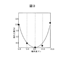
図3に結晶軸角度ズレに対する損失光量の実測値を示す。図3において、横軸は結晶軸角度ズレであり、縦軸は偏光フィルムで生じる損失光量である。実測値より、軸角度が±1°ずれると光の吸収量が約0.5%、軸角度が±2°ずれると光の吸収量が約2%増加することが分かっており、軸角度公差は±2°以内が望ましい。結晶軸角度ズレが±2°を越えると急激に損失光量が増加する。損失光量が増加すると輝度低下を引き起す。
【0021】
一般に、図2に示す液晶プロジェクタの製造工程では、光源1を除く照明光学系から投射レンズ3までの光学系において、輝度管理は所定の値に対し、輝度低下を略10%で管理している。この内、ダイクロイックミラ−で略5%、液晶表示素子で略7から8%輝度が変動し、また、この他の複数の光学レンズでも数%の変動があり、このような変動部品を組合せてト−タルの輝度変動を10%以内となるようにしている。従って、光の吸収量を約2%にする上記した水晶基板の結晶軸角度ズレの±2°は許容できる上限値とみなせる。
【0022】
つぎに、偏光フィルム41の透過軸を通過した光は、液晶表示素子20により映像信号(図示せず)の階調に応じて偏光方向が変化させられ、偏光フィルム51に入射し、偏光フィルム51の透過軸に平行な偏光成分は偏光フィルム51を透過するが、それ以外は偏光フィルム51で吸収される。
【0023】
偏光フィルム41及び51は、透過軸以外の偏光成分を吸収して発熱するため、偏光フィルム41及び51の表面および水晶基板42および52の表面を空冷することにより、発熱による温度上昇を抑制する。水晶基板42および52に高い熱伝導性が求められるのは、水晶基板42および52の表面からの放熱効果を向上させるためである。
【0024】
図4は、ガラス、水晶およびサファイヤを偏光フィルムの透明基板に用いた場合の、偏光フィルム温度を液晶プロジェクタで実測したもので、横軸に透明基板の板厚を縦軸に偏光フィルム温度を示している。温度測定の条件は次の通りである。
【0025】
周囲温度はTa25℃、光源は155W仕様の超高圧水銀ランプ、透過型液晶表示素子は0.7インチ、偏光フィルムのサイズは21.5mm × 18.0mm、透明基板サイズは23.5mm × 20.0mmで、測定場所はG入力側偏光板である。
【0026】
図4から明らかなように、3種とも、板厚が薄いほど基板の熱伝導性が向上するため、偏光フィルムの温度は低くなる。熱伝導率は、ガラスが0.55〜0.75(W/mK)に対して、水晶が5.4(W/mK)、サファイヤが42(W/mK)である。水晶は熱伝導率としてはサファイヤより劣るが、偏光板基板として使用した場合のガラスに対する温度低減効果(略10℃)は十分に確認された。水晶基板を用いる場合とサファイヤ基板を用いる場合との温度は、板厚が薄くなるほど差が小さくなり、0.3mm以下ではほぼ同等となった。水晶基板を用いる場合とサファイヤ基板を用いる場合との温度の差を2℃以下にするためには、板厚を1mm以下とすればよい。
【0027】
一般に、偏光フィルムは耐用年数と熱変形による色ムラ(輝度ムラ)の点から70℃以下で使用するのが望ましい。周囲温度の許容上限温度である35℃で偏光フィルムの温度を70℃とすると、周囲温度が常温の25℃の場合、偏光フィルムの温度は60℃となる。図4の周囲温度が25℃である測定値では、基板の板厚が1.0mmの場合、サファイヤ基板が約57℃、水晶基板が約59℃で、これ以上の温度差は性能の点から望ましくない。
【0028】
水晶を透明基板に用いた場合、板厚を0.3mmでも容易に加工できるが、基板の破壊強度を考慮すると0.3mm以上が望ましい。
【0029】
水晶の価格はサファイヤの価格に比べ約1/3であるので、図3で述べたような本発明による構成とし、従来のようなサファイヤ基板に比べ水晶基板を用いることにより、サファイヤ基板とほぼ同等な温度低減化を確保しながら大幅なコストダウンを実現することができる効果がある。
【0030】
また、水晶はサファイヤの価格に比べ安価であるので、水晶基板の外形サイズを大きくすることも可能となる。約2倍のサイズとしても、サファイヤの価格より安いので、水晶でサファイヤの約2倍のサイズにした場合、1倍のサイズのサファイヤよりさらに温度を下げることが可能となる。
【0031】
図5は偏光板の透明基板の平面精度による画像歪みを説明するための概念図である。図5において、24は図2に示す液晶プロジェクタで液晶表示素子20R,20G,20B上に形成された正常な画像例である。25はスクリーン19上に投影された歪曲した画像例を示す。
【0032】
透過型液晶表示素子20R,20G,20Bにて画像例24のような画像を形成した場合、通常はRGBそれぞれの画像例24が重なり合い、スクリーン19上に画像例24と同形状の白色画像が形成される。しかし、液晶表示素子の前後に配設された偏光板の透明基板の平面精度が低い場合には透明基板のレンズ効果により、RGB3色の画像が重なり合わない現象が発生する。たとえば、出射側偏光板5Gのみ平面精度が低い場合には、スクリーン19上に形成される画像は、Gについてのみ歪曲した画像例25のようになり、周辺部では画像が重なり合わず、白色とならないで着色がおこり、画素ズレとなる。このレンズ効果は屈折率に比例するため、透明基板に水晶(屈折率約1.55)を使用することでサファイヤ(屈折率約1.78)よりも上記現象を低減することが可能となる。
【0033】
さらに、モース硬度で比較するとサファイヤが9であるのに対して水晶は7である。モース硬度が低いほど加工性が良いので、サファイヤに比べ水晶が加工し易いことが明らかであり、サファイヤより水晶を用いた方が透明基板の平面精度を確保しやすく、加工費のコストダウンを図ることができる。一般的には、上記平面精度を満足するようにサファイヤを加工する場合には、板厚を0.5mm以上にするのが望ましいが、水晶を用いた場合は0.3mmでも加工が容易である。ただし、透明基板の破壊強度を考慮した場合0.3mm以上とするのが望ましい。
【0034】
なお、上記では液晶プロジェクタの実施の形態として図2で示した液晶表示素子を3枚使用する3板式の液晶プロジェクタについて述べたが、これに限定されるものではなく、例えば、液晶表示素子を1枚使用する単板式の液晶プロジェクタであってもよい。
【0035】
また、上記では、透過型液晶表示素子の前後に配設された偏光板の透明基板にサファイヤに代えて水晶を用いることを述べたが、用途はこれに限定されるものではなく、例えば液晶表示素子の液晶をその間に挟み込む2枚の対向する透明基板にも適用できることは明らかである。
【0036】
さらに、透過型液晶プロジェクタのみならず反射型液晶プロジェクタでも、偏光方向を揃えるためにまたは所望でない偏光方向成分を削減するために偏光板が用いられている。使用例として例えば特開2001−215491号公報、特開平10−312034号公報等がある。これらの反射型液晶プロジェクタにおいても、偏光板の透明基板として水晶基板が適用可能であることも明らかである。
【0037】
【発明の効果】
以上説明した通り、本発明によれば、偏光板を構成する透明基板に加工性が良くかつ熱伝導性の高い部材である水晶基板を用いた液晶プロジェクタを提供できる。これにより、偏光板の偏光フィルムの温度上昇を透明基板にサファイヤを用いた場合とほぼ同等とすることができ、コストダウンを実現することができる。また、水晶の加工のしやすさから透明基板の平面精度を確保でき、平面度による画像歪みも低減できる。
【図面の簡単な説明】
【図1】本発明による偏光板の構成図である。
【図2】本発明による偏光板を用いた透過型液晶プロジェクタの構成図である。
【図3】結晶軸角度ズレに対する損失光量を示す測定図ある。
【図4】ガラス、水晶およびサファイヤを偏光フィルムの透明基板に用いた場合の、偏光フィルム温度を示す測定図ある。
【図5】偏光フィルタの透明基板の平面精度による画像歪みを説明するための概念図である。
【符号の説明】
1・・・光源、20・・・液晶表示素子、3・・・投射レンズ、4・・・入射側偏光板、 5・・・出射側偏光板、6・・・第1レンズアレイ、7・・・第2レンズアレイ、8・・・偏光変換素子、9・・・集光レンズ、10・・・コンデンサレンズ、11・・・色合成プリズム、12・・・ダイクロイックミラ−、13・・・ダイクロイックミラ−、14、15、16・・・反射ミラ−、17、18・・・リレ−レンズ、19・・・スクリ−ン、21・・・光路、24・・・液晶表示素子20上に形成された正常な画像例、25・・・スクリーン19上に投影された歪曲した画像例、26・・・冷却用ファン、27・・・流路、41、51・・・偏光フィルム、42、52・・・水晶基板。[0001]
BACKGROUND OF THE INVENTION
The present invention relates to a liquid crystal projector that projects an image on a liquid crystal display element, and more particularly to a technique for efficiently radiating heat with respect to a polarizing film that becomes high temperature as the image becomes brighter.
[0002]
[Prior art]
In an optical system of a projector using a liquid crystal display element, at least one liquid crystal display element and a pair of polarizing films before and after the liquid crystal display element are used. This polarizing film has high heat shrinkability, and is generally used by being bonded to a transparent substrate with an adhesive material in order to prevent deformation when absorbing heat from the light source and generating heat. Hereinafter, a polarizing film bonded to the transparent substrate is referred to as a polarizing plate.
[0003]
Recently, as this transparent substrate, for example, as disclosed in Japanese Patent No. 3091183, sapphire has been used paying attention to the characteristic of high thermal conductivity. At this time, as described in the patent publication, the optical axis of the sapphire is made parallel or orthogonal to the incident polarized light so as not to affect the polarized light incident on the transparent substrate.
[0004]
[Problems to be solved by the invention]
Sapphire used as a material for the transparent substrate is very expensive compared to glass or the like. The transparent substrate is required to have high planar accuracy in order not to cause distortion in the image. However, since sapphire has high hardness, workability is poor and the polishing cost is higher than that of glass or the like.
[0005]
An object of the present invention is to solve the above-described problems and provide a liquid crystal projector using a member having good workability and high thermal conductivity as a transparent substrate of the polarizing film.
[0006]
[Means for solving the problems]
As a polarizing plate, a polarizing element is bonded to a quartz substrate having a plate thickness of 0.3 mm or more and 1.0 mm or less, and its optical axis is configured to be parallel or orthogonal to incident polarized light. With this configuration, compared to the case of using a sapphire substrate, it is possible to improve the workability and reduce the cost of the substrate with the same heat dissipation effect.
[0007]
DETAILED DESCRIPTION OF THE INVENTION
Hereinafter, embodiments of the present invention will be described in detail with reference to the drawings.
[0008]
1 and 2 are diagrams showing an embodiment of the present invention. FIG. 1 shows a configuration of a polarizing plate according to the present invention disposed before and after a transmissive liquid crystal display element, and FIG. 2 uses the polarizing plate. 1 shows the configuration of a transmissive liquid crystal projector. In FIG. 1 and FIG. 2, the same parts are indicated by the same reference numerals.
[0009]
The present invention is characterized in that in a liquid crystal projector using polarized light, quartz is used as a material for a holder of a polarizing element disposed on an optical path from a light source to a projection lens.
[0010]
Hereinafter, an embodiment of the present invention will be described with reference to FIG. In FIG. 2, the light beam emitted from the light source 1 enters the first lens array 6. The first lens array 6 divides an incident light beam into a plurality of light beams by a plurality of lens cells arranged in a matrix and efficiently guides the light to pass through the second lens array 7 and the polarization conversion element 8. Similar to the first lens array, the second lens array 7 having a plurality of lens cells arranged in a matrix form the shape of the lens cell of the first lens array 6 corresponding to each of the constituting lens cells, as a transmissive liquid crystal. Projecting to the
[0011]
In the process, white light emitted from the light source 1 is separated into three primary colors of red (R), green (G), and blue (B) by the dichroic mirrors 12 and 13, and the corresponding liquid
[0012]
Each of the liquid
[0013]
The images on the liquid
[0014]
The
[0015]
In addition, the
[0016]
The
[0017]
The liquid crystal projector configured as described above is required to be particularly small and to obtain a bright image. Therefore, the liquid crystal display element has been miniaturized and the efficiency of the light source has been improved. It is planned. Accordingly, light concentrates on the downsized liquid crystal display element, and the temperature rises due to heat generation due to light absorption. In addition, the temperature rises due to heat generated by light absorption even in a polarizing plate of approximately the same size as the liquid crystal display elements disposed before and after the liquid crystal display element. Therefore, the heat dissipation effect of the polarizing plate is enhanced and the temperature rise is prevented by cooling with a cooling fan or the like. In particular, the heat dissipation effect is further enhanced and the temperature rise is improved in the polarizing plate.
[0018]
FIG. 1 shows in detail the incident side polarizing plate, the outgoing side polarizing plate, and the transmissive liquid crystal display element. In FIG. 1, 41 and 51 are polarizing films, and 42 and 52 are crystal substrates which are transparent substrates to which the
[0019]
If the polarization direction of the linearly polarized light converted by the polarization conversion element 8 is the XX ′ direction (hereinafter referred to as the vertical direction) parallel to the paper surface orthogonal to the
[0020]
FIG. 3 shows an actual measurement value of the loss light quantity with respect to the crystal axis angle deviation. In FIG. 3, the horizontal axis is the crystal axis angle deviation, and the vertical axis is the amount of light loss generated in the polarizing film. From measured values, it is known that light absorption increases by about 0.5% when the shaft angle deviates by ± 1 °, and light absorption increases by about 2% when the shaft angle deviates by ± 2 °. Is preferably within ± 2 °. When the crystal axis angle deviation exceeds ± 2 °, the amount of lost light increases rapidly. Increasing the amount of lost light causes a decrease in brightness.
[0021]
In general, in the manufacturing process of the liquid crystal projector shown in FIG. 2, in the optical system from the illumination optical system excluding the light source 1 to the projection lens 3, the brightness management is managed at about 10% with respect to a predetermined value. . Of these, the luminance varies by about 5% for dichroic mirrors and by about 7 to 8% for liquid crystal display elements, and also by several percent for other optical lenses. The total luminance fluctuation is set to be within 10%. Therefore, ± 2 ° of the crystal axis angle deviation of the quartz substrate that makes the light absorption amount about 2% can be regarded as an allowable upper limit value.
[0022]
Next, the light passing through the transmission axis of the
[0023]
Since the polarizing
[0024]
Fig. 4 shows the measured temperature of a polarizing film with a liquid crystal projector when glass, quartz and sapphire are used for the transparent substrate of the polarizing film. The horizontal axis indicates the thickness of the transparent substrate, and the vertical axis indicates the polarizing film temperature. ing. The conditions for temperature measurement are as follows.
[0025]
Ambient temperature is Ta25 ° C., light source is 155 W ultra high pressure mercury lamp, transmissive liquid crystal display element is 0.7 inch, polarizing film size is 21.5 mm × 18.0 mm, transparent substrate size is 23.5 mm × 20. At 0 mm, the measurement location is the G input side polarizing plate.
[0026]
As is clear from FIG. 4, since the thermal conductivity of the substrate improves as the plate thickness decreases, the temperature of the polarizing film decreases. The thermal conductivity is 5.4 (W / mK) for quartz and 42 (W / mK) for sapphire versus 0.55 to 0.75 (W / mK) for glass. Although quartz is inferior to sapphire in terms of thermal conductivity, the temperature reduction effect (approximately 10 ° C.) on glass when used as a polarizing plate substrate has been sufficiently confirmed. The difference in temperature between using a quartz substrate and using a sapphire substrate decreases as the plate thickness decreases, and is substantially the same at 0.3 mm or less. In order to make the temperature difference between the case of using a quartz substrate and the case of using a
[0027]
In general, it is desirable to use a polarizing film at 70 ° C. or less from the viewpoint of service life and color unevenness (luminance unevenness) due to thermal deformation. Assuming that the temperature of the polarizing film is 70 ° C. at 35 ° C. which is an allowable upper limit temperature of the ambient temperature, the temperature of the polarizing film is 60 ° C. when the ambient temperature is 25 ° C. In the measured value in FIG. 4 where the ambient temperature is 25 ° C., when the thickness of the substrate is 1.0 mm, the sapphire substrate is about 57 ° C. and the quartz substrate is about 59 ° C. Not desirable.
[0028]
When quartz is used for the transparent substrate, it can be easily processed even if the plate thickness is 0.3 mm, but 0.3 mm or more is desirable in consideration of the breaking strength of the substrate.
[0029]
Since the price of quartz is about 1/3 of the price of sapphire, the configuration according to the present invention as described in FIG. 3 is adopted, and a quartz substrate is used in comparison with a conventional sapphire substrate. There is an effect that significant cost reduction can be realized while ensuring a reduction in temperature.
[0030]
Further, since quartz is cheaper than the price of sapphire, it is possible to increase the external size of the quartz substrate. Even if the size is about twice, it is cheaper than the price of sapphire, so when it is made about twice the size of sapphire with crystal, the temperature can be lowered further than that of sapphire of the size of 1 times.
[0031]
FIG. 5 is a conceptual diagram for explaining image distortion due to planar accuracy of the transparent substrate of the polarizing plate. In FIG. 5, 24 is a normal image example formed on the liquid
[0032]
When an image like the image example 24 is formed by the transmissive liquid
[0033]
Furthermore, when compared with Mohs hardness, the sapphire is 9, whereas the crystal is 7. The lower the Mohs hardness, the better the workability, so it is clear that quartz is easier to process than sapphire. Using sapphire makes it easier to ensure the flatness of the transparent substrate and reduces processing costs. be able to. Generally, when processing sapphire so as to satisfy the above planar accuracy, it is desirable to make the plate thickness 0.5 mm or more, but when using quartz, processing is easy even with 0.3 mm. . However, when considering the breaking strength of the transparent substrate, it is desirable that the thickness be 0.3 mm or more.
[0034]
In the above description, a three-plate type liquid crystal projector using three liquid crystal display elements shown in FIG. 2 is described as an embodiment of the liquid crystal projector. However, the present invention is not limited to this. A single-plate type liquid crystal projector using one sheet may be used.
[0035]
In the above description, it has been described that quartz is used instead of sapphire for the transparent substrate of the polarizing plate disposed before and after the transmissive liquid crystal display element, but the application is not limited to this. It is obvious that the present invention can also be applied to two opposing transparent substrates that sandwich the liquid crystal of the element therebetween.
[0036]
Further, not only in the transmission type liquid crystal projector but also in the reflection type liquid crystal projector, a polarizing plate is used in order to align the polarization direction or to reduce an undesired polarization direction component. Examples of use include, for example, Japanese Patent Application Laid-Open Nos. 2001-215491 and 10-312034. In these reflection type liquid crystal projectors, it is also clear that a quartz substrate can be applied as a transparent substrate of a polarizing plate.
[0037]
【The invention's effect】
As described above, according to the present invention, it is possible to provide a liquid crystal projector using a quartz substrate, which is a member having good workability and high thermal conductivity, as a transparent substrate constituting a polarizing plate. Thereby, the temperature rise of the polarizing film of a polarizing plate can be made substantially equivalent to the case where sapphire is used for a transparent substrate, and cost reduction can be realized. In addition, the flatness of the transparent substrate can be ensured from the ease of processing of quartz, and image distortion due to flatness can be reduced.
[Brief description of the drawings]
FIG. 1 is a configuration diagram of a polarizing plate according to the present invention.
FIG. 2 is a configuration diagram of a transmissive liquid crystal projector using a polarizing plate according to the present invention.
FIG. 3 is a measurement diagram showing a loss light amount with respect to a crystal axis angle shift.
FIG. 4 is a measurement diagram showing the polarizing film temperature when glass, quartz and sapphire are used for the transparent substrate of the polarizing film.
FIG. 5 is a conceptual diagram for explaining image distortion due to planar accuracy of a transparent substrate of a polarizing filter.
[Explanation of symbols]
DESCRIPTION OF SYMBOLS 1 ... Light source, 20 ... Liquid crystal display element, 3 ... Projection lens, 4 ... Incident side polarizing plate, 5 ... Outgoing side polarizing plate, 6 ... 1st lens array, 7 * .. Second lens array, 8... Polarization conversion element, 9... Condensing lens, 10 .. Condenser lens, 11... Color synthesis prism, 12 ... Dichroic mirror, 13. Dichroic mirror, 14, 15, 16 ... reflective mirror, 17, 18 ... relay lens, 19 ... screen, 21 ... optical path, 24 ... on the liquid
Claims (1)
前記液晶表示素子の入射側および出射側の少なくともいずれか一方に配置される偏光板が、水晶基板と偏光素子とを含み、該水晶基板と偏光素子とが互いに貼り合わせられており、
前記水晶基板の板厚が0.3mm以上1.0mm以下であり、
前記水晶基板の光学軸と前記偏光素子の吸収軸とのなす角度が、90±2°と0±2°の何れかであることを特徴とする液晶プロジェクタ。A light source unit that emits white light, a polarization conversion element that converts light emitted from the light source unit into linearly polarized light, a color separation unit that separates white light into three colors of red, green, and blue, and a video signal of each color A liquid crystal display element having a projection unit for projecting the optical image and a liquid crystal display element that converts the optical image according to
The polarizing plate disposed on at least one of the incident side and the emission side of the liquid crystal display element includes a crystal substrate and a polarizing element, and the crystal substrate and the polarizing element are bonded to each other,
The thickness of the quartz substrate is 0.3 mm or more and 1.0 mm or less ,
The liquid crystal projector , wherein an angle formed by the optical axis of the quartz substrate and the absorption axis of the polarizing element is either 90 ± 2 ° or 0 ± 2 ° .
Priority Applications (1)
| Application Number | Priority Date | Filing Date | Title |
|---|---|---|---|
| JP2002028904A JP3979106B2 (en) | 2002-02-06 | 2002-02-06 | LCD projector |
Applications Claiming Priority (1)
| Application Number | Priority Date | Filing Date | Title |
|---|---|---|---|
| JP2002028904A JP3979106B2 (en) | 2002-02-06 | 2002-02-06 | LCD projector |
Publications (3)
| Publication Number | Publication Date |
|---|---|
| JP2003228058A JP2003228058A (en) | 2003-08-15 |
| JP2003228058A5 JP2003228058A5 (en) | 2005-07-07 |
| JP3979106B2 true JP3979106B2 (en) | 2007-09-19 |
Family
ID=27749927
Family Applications (1)
| Application Number | Title | Priority Date | Filing Date |
|---|---|---|---|
| JP2002028904A Expired - Lifetime JP3979106B2 (en) | 2002-02-06 | 2002-02-06 | LCD projector |
Country Status (1)
| Country | Link |
|---|---|
| JP (1) | JP3979106B2 (en) |
Families Citing this family (1)
| Publication number | Priority date | Publication date | Assignee | Title |
|---|---|---|---|---|
| JP4363429B2 (en) | 2006-08-31 | 2009-11-11 | セイコーエプソン株式会社 | Polarizing plate, liquid crystal device, and electronic device |
-
2002
- 2002-02-06 JP JP2002028904A patent/JP3979106B2/en not_active Expired - Lifetime
Also Published As
| Publication number | Publication date |
|---|---|
| JP2003228058A (en) | 2003-08-15 |
Similar Documents
| Publication | Publication Date | Title |
|---|---|---|
| US7502078B2 (en) | Projection type display apparatus with means for supplying an air cooling stream to a gap between a light receiving surface of a prism and a third surface of a closed triangular prismatic housing | |
| US7092056B2 (en) | Quarter wavelength plate and projection type video display device using the same | |
| JP2006350291A (en) | Liquid crystal projector | |
| JP2006145644A (en) | Polarization splitter and projection display apparatus using the same | |
| JP4135088B2 (en) | Liquid crystal display device and liquid crystal projector | |
| JP2005250061A (en) | Optical unit, projection image display device and optical element used therefor | |
| JP4109901B2 (en) | Image display device | |
| JP2001201739A (en) | Projection mode video display device and optical parts | |
| JP2020042234A (en) | Electro-optic device and electronic device | |
| JP3979106B2 (en) | LCD projector | |
| JP2004077850A (en) | Liquid crystal display | |
| JP2003131164A (en) | Video display element and video display device using the same | |
| JP5596930B2 (en) | Projection display | |
| JP2004246178A (en) | Optical unit, projection type video display device and polarizing plate used therein | |
| JP4043294B2 (en) | LCD projector | |
| JP4125631B2 (en) | Projection display | |
| JP4880505B2 (en) | Projection display | |
| JP5193516B2 (en) | Projection display | |
| JP4652122B2 (en) | Projection-type image display device, optical member and optical unit used therefor | |
| JP2006039344A (en) | Polarizing plate and liquid crystal projector | |
| JPH10319503A (en) | Picture projection display device and optical modulation unit for the same | |
| JP2005107363A (en) | Image display device | |
| JP2002098937A (en) | Three-plate reflecting type liquid crystal projector | |
| JP2007114328A (en) | Optical member and projection image display device using same | |
| JP2009265366A (en) | Liquid crystal display device |
Legal Events
| Date | Code | Title | Description |
|---|---|---|---|
| A521 | Request for written amendment filed |
Free format text: JAPANESE INTERMEDIATE CODE: A523 Effective date: 20041029 |
|
| A621 | Written request for application examination |
Free format text: JAPANESE INTERMEDIATE CODE: A621 Effective date: 20041029 |
|
| RD01 | Notification of change of attorney |
Free format text: JAPANESE INTERMEDIATE CODE: A7421 Effective date: 20060419 |
|
| A977 | Report on retrieval |
Free format text: JAPANESE INTERMEDIATE CODE: A971007 Effective date: 20061027 |
|
| A131 | Notification of reasons for refusal |
Free format text: JAPANESE INTERMEDIATE CODE: A131 Effective date: 20061107 |
|
| A521 | Request for written amendment filed |
Free format text: JAPANESE INTERMEDIATE CODE: A523 Effective date: 20061228 |
|
| A131 | Notification of reasons for refusal |
Free format text: JAPANESE INTERMEDIATE CODE: A131 Effective date: 20070327 |
|
| A521 | Request for written amendment filed |
Free format text: JAPANESE INTERMEDIATE CODE: A523 Effective date: 20070516 |
|
| TRDD | Decision of grant or rejection written | ||
| A01 | Written decision to grant a patent or to grant a registration (utility model) |
Free format text: JAPANESE INTERMEDIATE CODE: A01 Effective date: 20070605 |
|
| A61 | First payment of annual fees (during grant procedure) |
Free format text: JAPANESE INTERMEDIATE CODE: A61 Effective date: 20070618 |
|
| R151 | Written notification of patent or utility model registration |
Ref document number: 3979106 Country of ref document: JP Free format text: JAPANESE INTERMEDIATE CODE: R151 |
|
| FPAY | Renewal fee payment (event date is renewal date of database) |
Free format text: PAYMENT UNTIL: 20100706 Year of fee payment: 3 |
|
| FPAY | Renewal fee payment (event date is renewal date of database) |
Free format text: PAYMENT UNTIL: 20100706 Year of fee payment: 3 |
|
| FPAY | Renewal fee payment (event date is renewal date of database) |
Free format text: PAYMENT UNTIL: 20110706 Year of fee payment: 4 |
|
| FPAY | Renewal fee payment (event date is renewal date of database) |
Free format text: PAYMENT UNTIL: 20110706 Year of fee payment: 4 |
|
| FPAY | Renewal fee payment (event date is renewal date of database) |
Free format text: PAYMENT UNTIL: 20120706 Year of fee payment: 5 |
|
| FPAY | Renewal fee payment (event date is renewal date of database) |
Free format text: PAYMENT UNTIL: 20130706 Year of fee payment: 6 |
|
| S111 | Request for change of ownership or part of ownership |
Free format text: JAPANESE INTERMEDIATE CODE: R313111 |
|
| R350 | Written notification of registration of transfer |
Free format text: JAPANESE INTERMEDIATE CODE: R350 |
|
| S111 | Request for change of ownership or part of ownership |
Free format text: JAPANESE INTERMEDIATE CODE: R313111 |
|
| R350 | Written notification of registration of transfer |
Free format text: JAPANESE INTERMEDIATE CODE: R350 |
|
| R250 | Receipt of annual fees |
Free format text: JAPANESE INTERMEDIATE CODE: R250 |
|
| R250 | Receipt of annual fees |
Free format text: JAPANESE INTERMEDIATE CODE: R250 |
|
| R250 | Receipt of annual fees |
Free format text: JAPANESE INTERMEDIATE CODE: R250 |
|
| R250 | Receipt of annual fees |
Free format text: JAPANESE INTERMEDIATE CODE: R250 |
|
| S111 | Request for change of ownership or part of ownership |
Free format text: JAPANESE INTERMEDIATE CODE: R313111 |
|
| R350 | Written notification of registration of transfer |
Free format text: JAPANESE INTERMEDIATE CODE: R350 |
|
| EXPY | Cancellation because of completion of term |