JP3979092B2 - Method for applying treatment liquid and optical lens processing apparatus - Google Patents
Method for applying treatment liquid and optical lens processing apparatus Download PDFInfo
- Publication number
- JP3979092B2 JP3979092B2 JP2002001624A JP2002001624A JP3979092B2 JP 3979092 B2 JP3979092 B2 JP 3979092B2 JP 2002001624 A JP2002001624 A JP 2002001624A JP 2002001624 A JP2002001624 A JP 2002001624A JP 3979092 B2 JP3979092 B2 JP 3979092B2
- Authority
- JP
- Japan
- Prior art keywords
- optical lens
- treatment liquid
- lens
- plastic
- processing apparatus
- Prior art date
- Legal status (The legal status is an assumption and is not a legal conclusion. Google has not performed a legal analysis and makes no representation as to the accuracy of the status listed.)
- Expired - Fee Related
Links
Images

Landscapes
- Ink Jet (AREA)
- Surface Treatment Of Optical Elements (AREA)
- Application Of Or Painting With Fluid Materials (AREA)
Description
【0001】
【発明の属する技術分野】
本発明は、処理液体の塗布方法、これを用いた光学用レンズの製造方法及び光学用レンズ加工装置に関する。
【0002】
【従来の技術】
プラスチックメガネレンズ等の光学用レンズにおいては、表面にプライマー加工、ハードコート加工、染色加工、および反射防止加工等の処理を施し、性能、機能の向上を図ることが一般に行われている。
【0003】
プライマー加工は、光学用レンズ基材とハードコート膜との密着性向上、耐衝撃性向上等の機能を付与する加工である。プラスチックメガネレンズにおいては、プライマー液をプラスチックメガネレンズ表面に塗布、加熱硬化処理する方法が広く用いられており、従来、主に浸漬方式が用いられてきた。浸漬方式とは、プラスチックメガネレンズを治具で保持し、プライマー液中に浸漬、放置後、引き上げることによりプライマー膜を形成する方法である。
【0004】
また、ハードコート加工は、光学用レンズ表面の耐久性向上、蒸着膜との密着性向上、染色性の安定化等、多くの機能を付与する加工である。プラスチックメガネレンズにおいては、ハードコート液をプラスチックメガネレンズ表面に塗布、加熱硬化処理する方法が広く用いられており、従来、主に浸漬方式及びスピンコーティング方式が用いられてきた。浸漬方式とは、プラスチックメガネレンズを治具で保持し、ハードコート液中に浸漬、放置後、引き上げることによりハードコート膜を形成する方法であり、スピンコーティング方式とは、プラスチックメガネレンズ表面にハードコート液を吐出し、高速回転させることによりハードコート膜を形成する方法である。
【0005】
また、染色加工は、特にプラスチックメガネレンズの製造工程において、ファッション性を付加することを目的として、多様な色の染色を施す加工であり、その方式として、従来、浸漬方式が用いられてきた。浸漬方式とは、界面活性剤により染料微粒子を分散させた熱水中に、プラスチックメガネレンズを浸漬、引き上げる方法である。
【0006】
また、反射防止加工は、光学用レンズの表面反射を防止する加工である。表面反射が生じると、光学系の透過率を低下させ、結像に寄与しない光の増加をもたらし、像のコントラストを低下させる。よって、プラスチックメガネレンズの場合、反射防止加工を施すことにより、装用者は良好な視界を得ることができる。プラスチックメガネレンズの反射防止膜は、従来、主に真空蒸着法により、単層膜または多層膜として形成されていた。最近では、反射防止機能を有する硬化性液体も考案されている。
【0007】
一方、処理液体を光学用レンズの必要な場所にだけ塗布できるコーティング技術として、インクジェット方式およびスプレー方式による塗布方法が提案されている。インクジェット方式およびスプレー方式による塗布方法は、処理液体を微小なノズルから液滴として吐出する方法である。インクジェット方式およびスプレー方式では、装置を小型化できる上、少ない電力で塗布でき、しかも処理液体の利用効率が高いことから、生産コストを低減できると共に、溶剤使用量の低減、廃棄物の低減等、環境対策の進歩が期待できる。
【0008】
【発明が解決しようとする課題】
しかしながら、インクジェット方式およびスプレー方式を用いて光学用レンズの表面に処理液体を塗布する場合、次のような問題があった。
【0009】
つまり、処理液体が滴状に微細化される際、ミスト状の処理液体が発生、浮遊するため、片面ずつ処理液体を塗布、硬化した場合、塗布面に対して反対の面に付着したミスト状の処理液体によって外観不良が発生する点である。
【0010】
本発明は、このような問題点を解決するもので、処理液体を滴状に微細化して光学用レンズの表面に塗布する処理液体の塗布方法において、ミスト状の処理液体の付着によって発生する外観不良を防ぐ方法を提供することを目的とする。
【0011】
【課題を解決するための手段】
本発明者は、前記課題を解決するために鋭意検討を行った結果、インクジェット方式およびスプレー方式を用いて処理液体を滴状に微細化し、光学用レンズの表面に塗布する処理液体の塗布方法において、処理液体のレベリング性能によって塗布面を平滑化させること、さらに詳しくは、処理液体を光学用レンズに対して両面同時に塗布すること、又は光学用レンズの一方の面に塗布している時間内に他方の面の塗布を開始すること、又は光学用レンズの一方の面に塗布した後、塗布面が乾燥する前に他方の面の塗布を開始することが、ミスト状の処理液体の付着によって発生する外観不良を防ぐ方法として有効であることを知見した。
【0012】
つまり、処理液体が滴状に微細化される際、ミスト状の処理液体が発生、浮遊するため、片面ずつ処理液体を塗布、硬化した場合、塗布面に対して反対の面に付着したミスト状の処理液体によって斑点状の外観不良が発生する。しかし、両面同時または一方の面が乾燥する前に他方の面を塗布すれば、塗布された液体のレベリング性能が有効に働くため、平滑化される。なお、ここでいうレベリング性能とは、処理液体自身の持つ流動性によって、均一な塗布面を形成する性能をいう。
【0013】
従って、目的を達成するために、請求項1記載の発明は、インクジェット方式にて処理液体を滴状に微細化して光学用レンズの表面に塗布する塗布工程と、前記処理液体のレベリング性能によって塗布面を平滑化させるレベリング工程とを有し、前記処理液体を前記光学用レンズの一方の面に塗布し、その終了後、前記一方の面に塗布された前記処理液体が前記一方の面全体において流動性をもっている状態で、他方の面の塗布を開始することを特徴とする処理液体の塗布方法を提供する。
【0019】
請求項2記載の発明は、前記光学用レンズが、プラスチックメガネレンズであることを特徴とする請求項1記載の処理液体の塗布方法を提供する。
【0021】
請求項3記載の発明は、前記処理液体が、前記光学用レンズのプライマーの原料または反射防止膜の原料のいずれか一種以上であることを特徴とする請求項1または2に記載の処理液体の塗布方法を提供する。
【0023】
請求項4記載の発明は、前記処理液体が、顔料および/または染料を含むことを特徴とする請求項3に記載の処理液体の塗布方法を提供する。
【0027】
請求項5記載の発明は、請求項1記載の処理液体の塗布方法に用いる光学用レンズ加工装置であって、前記光学用レンズを保持、搬送、および反転する手段と、前記光学用レンズの一方面側に配置されたインクジェット式記録ヘッドと、前記光学用レンズと前記インクジェット式記録ヘッドを相対位置決めする手段とを具備することを特徴とする光学用レンズ加工装置を提供する。
【0029】
【発明の実施の形態】
本発明における光学用レンズとしては、メガネレンズ、調光用レンズ、サングラス、カメラレンズ、望遠鏡レンズ、拡大鏡レンズ、プロジェクターレンズ、ピックアップレンズ、マイクロレンズ等が挙げられる。
【0030】
本発明の液体塗布手段の一つであるインクジェット方式は、10〜100μm径の微小なノズル開口部と圧力発生素子とが設けられた圧力室に処理液体が充填され、圧力発生素子を電子的に制御することによって圧力室内の処理液体を加圧し、その圧力で、ノズル開口部から処理液体を微小な液滴として吐出するものである。圧力発生素子の種類により、ピエゾ素子による圧電振動子を用いたピエゾ方式や、発熱素子を用いて処理液体を加熱して気泡を発生させ、その圧力を利用するバブルジェット(登録商標)方式等、種々の方式がある。本発明では、いずれのインクジェット方式も用いることができる。
【0031】
また、スプレー方式には、圧縮エアで霧化するエア霧化式、あるいは材料に高圧力をかけ、ノズルチップより吐出させるエアレス霧化式等が挙げられ、処理液体の粘度や吐出量に応じて適宜選択して使用することができる。
【0032】
上記インクジェットおよびスプレーの各方式により吐出する処理液体としては、光学用レンズの原料の一部、光学用レンズの原料そのもの、光学用レンズのハードコート膜原料の一部、光学用レンズのハードコート膜原料そのもの、光学用レンズのプライマー原料の一部、光学用レンズのプライマー原料そのもの、光学用レンズの反射防止膜原料の一部および光学用レンズの反射防止膜原料そのもの等が挙げられるが、それらは硬化方法によって使い分けられる。例えば、紫外線、電子線またはマイクロ波等を用いて光学用レンズの原料、ハードコート膜原料、プライマー原料および反射防止膜原料を硬化させる場合には、反応開始剤、触媒、溶剤および加水分解反応を進行させるための水等を添加しなくても硬化反応が進行するため、それらを除いた光学用レンズ原料の一部、ハードコート膜原料の一部、プライマー原料の一部および反射防止膜原料の一部を用いればよい。一方、加熱によって光学用レンズ原料、ハードコート膜原料、プライマー原料および反射防止膜原料を硬化させる場合には、反応開始剤、触媒、溶剤および加水分解反応を進行させるための水等を添加しなければ硬化反応が進行しないため、これらを含んだ光学用レンズ原料、ハードコート膜原料、プライマー原料および反射防止膜原料を用いる必要がある。また、これらの処理液体に染料および/または顔料を含ませることで、着色することも可能である。
【0033】
以下、本発明の実施例を、プラスチックメガネレンズを例に、図面に基づいて説明するが、これらに限定されるものではない。
【0034】
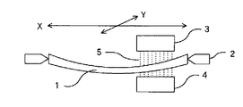
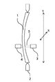
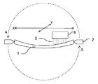
図1は、本発明によるインクジェット方式のプラスチックメガネレンズ加工装置の一例を示す図である。プラスチックメガネレンズ1は、保持部材2によって保持されており、ピエゾ方式のインクジェット式記録ヘッド3及び4より、処理液体5が吐出される構造となっている。図1では、インクジェット式記録ヘッド3及び4が、X方向及びY方向に移動するようになっているが、プラスチックメガネレンズ1側を移動させても、両方を移動させてもよい。また、図示はしないが、本加工装置は、相対位置決め手段により、プラスチックメガネレンズ1とインクジェット式記録ヘッド3及び4との相対位置を制御する機構を有している。プラスチックメガネレンズとインクジェット式記録ヘッドとの最短距離は、被塗布面が凹形状の場合、プラスチックメガネレンズの最外周部とインクジェット式記録ヘッドの距離、被塗布面が凸形状の場合はプラスチックメガネレンズの中心部とインクジェット式記録ヘッドの距離であり、10mm以下が望ましい。さらに液滴の着弾位置の精度および塗布面の均一性を考慮すると、2mm以下が望ましい。また、図1では、平置きされたプラスチックメガネレンズ1に対して処理液体5を塗布しているが、図2に示すように、縦置きされたプラスチックメガネレンズ1に対して処理液体5を塗布してもよい。
【0035】
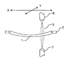
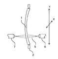
また、図3は、本発明によるスプレー方式のプラスチックメガネレンズ加工装置の一例を示す図である。プラスチックメガネレンズ1は、保持部材2によって保持されており、エア霧化式のスプレーノズル6及び7より、処理液体5が吐出される構造となっている。図3では、スプレーノズル6及び7が、X方向及びY方向に移動するようになっているが、プラスチックメガネレンズ1側を移動させても、両方を移動させてもよい。また、図示はしないが、本加工装置は、相対位置決め手段により、プラスチックメガネレンズ1とスプレーノズル6及び7との相対位置を制御する機構を有している。プラスチックメガネレンズとスプレーノズルとの最短距離は、被塗布面が凹形状の場合はプラスチックメガネレンズの最外周部とスプレーノズルの距離、被塗布面が凸形状の場合はプラスチックメガネレンズの中心部とスプレーノズルの距離であり、300mm以下が望ましい。さらに塗布面の均一性を考慮すると、100mm以下が望ましい。また、図3では、平置きされたプラスチックメガネレンズ1に対して処理液体5を塗布しているが、図4に示すように、縦置きされたプラスチックメガネレンズ1に対して処理液体5を塗布してもよい。
【0036】
また、図5は、本発明によるインクジェット方式プラスチックメガネレンズ加工装置の他の例を示す図である。プラスチックメガネレンズ1は、保持部材2によって保持されており、ピエゾ方式のインクジェット式記録ヘッド8より、処理液体5が吐出される構造となっている。図5ではインクジェット式記録ヘッド8がX方向及びY方向に移動するようになっているが、プラスチックメガネレンズ1側を移動させても、両方を移動させてもよい。また、図示はしないが、本加工装置には、相対位置決め手段により、プラスチックメガネレンズ1とインクジェット式記録ヘッド8の相対位置を制御する機構を有している。プラスチックメガネレンズとインクジェット式記録ヘッドとの最短距離は、被塗布面が凹形状の場合はプラスチックメガネレンズの最外周部とインクジェット式記録ヘッドの距離、凸形状の場合はプラスチックメガネレンズの中心部とインクジェット式記録ヘッドの距離であり、10mm以下が望ましい。さらに液滴の着弾位置の精度および塗布面の均一性を考慮すると、2mm以下が望ましい。また、本加工装置は、プラスチックメガネレンズ1を保持した保持部材2をAまたはAとは反対方向に反転させる機構を有している。図6では保持部材2を反転させているが、インクジェット式記録ヘッド8を反転させてもよい。
【0037】
また、図6は、本発明によるスプレー方式プラスチックメガネレンズ加工装置の他の例を示す図である。プラスチックメガネレンズ1は、保持部材2によって保持されており、エア霧化式のスプレーノズル9より、処理液体4が吐出される構造となっている。図6ではスプレーノズル9がX方向及びY方向に移動するようになっているが、プラスチックメガネレンズ1側を移動させても、両方を移動させてもよい。また、図示はしないが、本加工装置には、相対位置決め手段により、プラスチックメガネレンズ1とスプレーノズル9の相対位置を制御する機構を有している。プラスチックメガネレンズとスプレーノズルとの最短距離は、被塗布面が凹形状の場合はプラスチックレンズの最外周部とスプレーノズルの距離、被塗布面が凸形状の場合はプラスチックメガネレンズの中心部とスプレーノズルの距離であり、300mm以下が望ましい。さらに塗布面の均一性を考慮すると、100mm以下が望ましい。また、本加工装置は、プラスチックメガネレンズ1を保持した保持部材2をAまたはAとは反対方向に反転させる機構を有している。図6では保持部材2を反転させているが、スプレーノズル9を反転させてもよい。
【0038】
(実施例1)
図1に示すような装置を用いて、予めアセトンにて洗浄したチオウレタン系のプラスチックメガネレンズ1に対し、駆動周波数4.5kHzに設定したインクジェット式記録ヘッド3及び4よりシリコーン系ハードコート液をそれぞれ0.09gずつ同時に連続吐出させ、両面同時塗布した。塗布後、プラスチックメガネレンズ1を保持部材2から取り外し、120℃で90分間硬化した。
【0039】
このようにして作られたハードコートレンズは、ハードコート液のレベリング性能が有効に働き、良好な外観であった。
【0040】
(実施例2)
図1に示すような装置を用いて、予めアセトンにて洗浄したチオウレタン系のプラスチックメガネレンズ1に対し、駆動周波数4.5kHzに設定したインクジェット式記録ヘッド3よりシリコーン系ハードコート液0.09gを連続吐出させた。さらに、インクジェット式記録ヘッド3の吐出が完了する前に、同様に設定したインクジェット式記録ヘッド4よりシリコーン系ハードコート液0.09gを連続吐出させ、両面塗布した。塗布後、プラスチックメガネレンズ1を保持部材2から取り外し、120℃で90分間硬化した。
【0041】
このようにして作られたハードコートレンズは、ハードコート液のレベリング性能が有効に働き、良好な外観であった。
【0042】
(実施例3)
図3に示すような装置を用いて、予めアセトンで洗浄したチオウレタン系のプラスチックメガネレンズ1に対して、空気圧0.20MPaに設定したスプレーノズル6及び7より、シリコーン系ハードコート液をそれぞれ0.09gずつ連続吐出させ、両面同時塗布した。塗布後、プラスチックメガネレンズ1を保持部材2から取り外し、120℃で90分間硬化した。
【0043】
このようにして作られたハードコートレンズは、ハードコート液のレベリング性能が有効に働き、良好な外観であった。
【0044】
(実施例4)
図5に示すような装置を用いて、予めアセトンで洗浄したチオウレタン系のプラスチックメガネレンズ1に対し、駆動周波数を4.5kHzに設定したインクジェット式記録ヘッド8よりシリコーン系ハードコート液0.09gを連続吐出させ、一方の面への塗布を行った。塗布後、直ちにプラスチックメガネレンズ1を反転させ、同様に反対面への塗布を行った。塗布後、プラスチックメガネレンズ1を保持部材2から取り外し、120℃で90分間硬化した。
【0045】
このようにして作られたハードコートレンズは、ハードコート液のレベリング性能が有効に働き、良好な外観であった。
【0046】
(実施例5)
実施例4の条件のうち、プラスチックメガネレンズ1を反転後、反対面を塗布する前の放置時間を60秒にした。このようにして作られたハードコートレンズは、ハードコート液のレベリング性能が有効に働き、良好な外観であった。
【0047】
(実施例6)
実施例4の条件のうち、プラスチックメガネレンズ1を反転後、反対面を塗布する前の放置時間を180秒にした。このようにして作られたハードコートレンズは、ハードコート液のレベリング性能が有効に働き、良好な外観であった。
【0048】
(比較例1)
実施例4のうち、プラスチックメガネレンズ1の反対面へ塗布する前に、80℃で40分間仮焼成した。
【0049】
しかし、このようにして作られたハードコートレンズは、反対塗布面へのミスト状ハードコート液の付着が外観にそのまま残り、外観不良となった。
【0050】
(実施例7)
図6に示すような装置を用いて、予めアセトンで洗浄したチオウレタン系のプラスチックメガネレンズ1に対し、空気圧0.20MPaに設定したスプレーノズル9より、シリコーン系ハードコート液0.09gを連続吐出させ、一方の面への塗布を行った。塗布後、直ちにプラスチックメガネレンズ1を反転させ、同様に反対面への塗布を行った。塗布後、プラスチックメガネレンズ1を固定部材2から取り出した後、120℃で90分間硬化した。
【0051】
このようにして作られたハードコートレンズは、ハードコート液のレベリング性能が有効に働き、良好な外観であった。
【0052】
(比較例2)
実施例7のうち、プラスチックメガネレンズ1の反対面へ塗布する前に、80℃で40分間仮焼成した。
【0053】
しかし、このようにして作られたハードコートレンズは、反対塗布面へのミスト状ハードコート液の付着が外観にそのまま残り、外観不良となった。
【0054】
本実施例では、プラスチックメガネレンズのハードコーティングを例にとって説明したが、その他光学用レンズの原料、ハードコート膜原料、プライマー原料等の各種処理液体、これらの処理液体に染料および/または顔料を含ませたもの及び反射防止膜原料についても同様な効果が得られる。
【0055】
【発明の効果】
以上述べたように、本発明によれば、光学用レンズに対する微細化した処理液体の塗布方法において、ミスト状の処理液体の付着によって発生する外観不良を防ぐことができる。
【図面の簡単な説明】
【図1】インクジェット方式のプラスチックメガネレンズ加工装置概略図。
【図2】図1において、プラスチックメガネレンズが縦置きされた場合を示す概略図。
【図3】スプレー方式のプラスチックメガネレンズ加工装置概略図。
【図4】図3において、プラスチックメガネレンズが縦置きされた場合を示す概略図。
【図5】インクジェット方式のプラスチックメガネレンズ加工装置概略図。
【図6】スプレー方式のプラスチックメガネレンズ加工装置概略図。
【符号の説明】
1…プラスチックメガネレンズ
2…保持部材
3…インクジェット式記録ヘッド
4…インクジェット式記録ヘッド
5…処理液体
6…スプレーノズル
7…スプレーノズル
8…インクジェット式記録ヘッド
9…スプレーノズル[0001]
BACKGROUND OF THE INVENTION
The present invention relates to a method for applying a treatment liquid, a method for manufacturing an optical lens using the same, and an optical lens processing apparatus.
[0002]
[Prior art]
In an optical lens such as a plastic eyeglass lens, it is generally performed to improve performance and function by subjecting the surface to processing such as primer processing, hard coat processing, dyeing processing, and antireflection processing.
[0003]
The primer processing is processing for imparting functions such as improvement in adhesion between the optical lens substrate and the hard coat film, and improvement in impact resistance. In plastic eyeglass lenses, a method in which a primer solution is applied to the surface of the plastic eyeglass lens and heat-cured is widely used. Conventionally, an immersion method has been mainly used. The dipping method is a method of forming a primer film by holding a plastic spectacle lens with a jig, dipping it in a primer solution, leaving it, and then pulling it up.
[0004]
The hard coat process is a process that provides many functions such as improving the durability of the optical lens surface, improving the adhesion to the deposited film, and stabilizing the dyeability. In plastic eyeglass lenses, a method of applying a hard coat solution to the surface of a plastic eyeglass lens and heat-curing it has been widely used. Conventionally, an immersion method and a spin coating method have been mainly used. The immersion method is a method of forming a hard coat film by holding a plastic spectacle lens with a jig, immersing it in a hard coat solution, leaving it, and then pulling it up. This is a method of forming a hard coat film by discharging a coating liquid and rotating it at a high speed.
[0005]
The dyeing process is a process of dyeing various colors for the purpose of adding fashionability, particularly in the manufacturing process of plastic eyeglass lenses, and an immersion method has been conventionally used as the method. The dipping method is a method in which a plastic spectacle lens is dipped and pulled up in hot water in which dye fine particles are dispersed with a surfactant.
[0006]
The antireflection process is a process for preventing the surface reflection of the optical lens. When surface reflection occurs, the transmittance of the optical system is lowered, the light that does not contribute to imaging is increased, and the contrast of the image is lowered. Therefore, in the case of a plastic eyeglass lens, the wearer can obtain a good field of view by performing antireflection processing. Conventionally, an antireflection film of a plastic spectacle lens has been formed as a single layer film or a multilayer film mainly by a vacuum deposition method. Recently, a curable liquid having an antireflection function has also been devised.
[0007]
On the other hand, as a coating technique capable of applying the treatment liquid only to a necessary place of the optical lens, an application method using an ink jet method and a spray method has been proposed. The application method by the ink jet method and the spray method is a method of discharging the processing liquid as droplets from a minute nozzle. In the inkjet method and spray method, the apparatus can be downsized, and can be applied with a small amount of power, and since the processing liquid is used efficiently, the production cost can be reduced, the amount of solvent used, the amount of waste, etc. Advances in environmental measures can be expected.
[0008]
[Problems to be solved by the invention]
However, when the treatment liquid is applied to the surface of the optical lens using the ink jet method and the spray method, there are the following problems.
[0009]
In other words, when the treatment liquid is refined into droplets, a mist-like treatment liquid is generated and floats. Therefore, when the treatment liquid is applied and cured one side at a time, the mist is attached to the surface opposite to the application surface. This is the point that appearance defects are caused by the treatment liquid.
[0010]
The present invention solves such problems, and an appearance generated by adhesion of a mist-like treatment liquid in a treatment liquid application method in which a treatment liquid is finely formed into droplets and applied to the surface of an optical lens. An object is to provide a method for preventing defects.
[0011]
[Means for Solving the Problems]
As a result of intensive studies to solve the above problems, the present inventor has obtained a treatment liquid coating method in which the treatment liquid is finely formed into droplets using an inkjet method and a spray method and applied to the surface of an optical lens. Smoothing the application surface by leveling performance of the treatment liquid, more specifically, applying the treatment liquid to both sides of the optical lens at the same time, or applying the treatment liquid to one side of the optical lens within the time The application of the other surface, or the application of the other surface before the application surface dries after applying to one surface of the optical lens, occurs due to the adhesion of the mist-like processing liquid It was found that it is effective as a method for preventing the appearance defect.
[0012]
In other words, when the treatment liquid is refined into droplets, a mist-like treatment liquid is generated and floats. Therefore, when the treatment liquid is applied and cured one side at a time, the mist is attached to the surface opposite to the application surface. This treatment liquid causes spotted appearance defects. However, if the other surface is applied at the same time on both sides or before one surface is dried, the leveling performance of the applied liquid works effectively, so that it is smoothed. In addition, leveling performance here means the performance which forms a uniform application | coating surface with the fluidity | liquidity which processing liquid itself has.
[0013]
Therefore, in order to achieve the object, the invention according to
[0019]
According to a second aspect of the present invention, there is provided the processing liquid coating method according to the first aspect, wherein the optical lens is a plastic spectacle lens.
[0021]
According to a third aspect of the present invention, in the treatment liquid according to the first or second aspect, the treatment liquid is at least one of a raw material for a primer of the optical lens and a raw material for an antireflection film. An application method is provided.
[0023]
According to a fourth aspect of the present invention, there is provided the processing liquid application method according to the third aspect, wherein the processing liquid contains a pigment and / or a dye.
[0027]
A fifth aspect of the present invention is an optical lens processing apparatus used in the processing liquid coating method according to the first aspect, wherein the optical lens is held, transported and reversed, and one of the optical lenses. There is provided an optical lens processing apparatus comprising: an ink jet recording head disposed on a surface side; and means for relatively positioning the optical lens and the ink jet recording head.
[0029]
DETAILED DESCRIPTION OF THE INVENTION
Examples of the optical lens in the present invention include a spectacle lens, a dimming lens, sunglasses, a camera lens, a telescope lens, a magnifying lens, a projector lens, a pickup lens, and a microlens.
[0030]
The ink jet system, which is one of the liquid applying means of the present invention, is filled with a processing liquid in a pressure chamber provided with a fine nozzle opening having a diameter of 10 to 100 μm and a pressure generating element, and the pressure generating element is electronically By controlling the pressure, the processing liquid in the pressure chamber is pressurized, and the processing liquid is discharged as fine droplets from the nozzle opening at that pressure. Depending on the type of pressure generating element, a piezo method using a piezoelectric vibrator with a piezo element, a bubble jet (registered trademark) method that generates bubbles by heating a processing liquid using a heating element, and the like, There are various methods. In the present invention, any ink jet method can be used.
[0031]
In addition, the spray method includes an air atomization type that atomizes with compressed air, or an airless atomization type that applies high pressure to the material and discharges it from the nozzle tip, etc., depending on the viscosity and discharge amount of the processing liquid It can be appropriately selected and used.
[0032]
The processing liquid discharged by each of the ink jet and spray methods includes a part of the raw material for the optical lens, the raw material for the optical lens itself, a part of the raw material for the optical lens hard coat, and the hard coat film for the optical lens. The raw material itself, a part of the optical lens primer raw material, the optical lens primer raw material itself, a part of the optical lens antireflection film raw material, the optical lens antireflection film raw material itself, etc. It is properly used depending on the curing method. For example, when curing an optical lens raw material, a hard coat film raw material, a primer raw material, and an antireflection film raw material using ultraviolet rays, electron beams, or microwaves, a reaction initiator, a catalyst, a solvent, and a hydrolysis reaction are performed. Since the curing reaction proceeds without adding water or the like to advance, a part of the optical lens raw material excluding them, a part of the hard coat film raw material, a part of the primer raw material, and the antireflection film raw material A part may be used. On the other hand, when curing optical lens raw material, hard coat film raw material, primer raw material, and antireflection film raw material by heating, a reaction initiator, a catalyst, a solvent, water for proceeding the hydrolysis reaction, etc. must be added. Since the curing reaction does not proceed, it is necessary to use an optical lens material, a hard coat film material, a primer material, and an antireflection film material containing them. Moreover, it is also possible to color by including dye and / or a pigment in these process liquids.
[0033]
Hereinafter, examples of the present invention will be described with reference to the drawings taking a plastic spectacle lens as an example, but the present invention is not limited thereto.
[0034]
FIG. 1 is a diagram showing an example of an inkjet type plastic eyeglass lens processing apparatus according to the present invention. The
[0035]
FIG. 3 is a view showing an example of a spray-type plastic spectacle lens processing apparatus according to the present invention. The
[0036]
FIG. 5 is a diagram showing another example of an inkjet plastic eyeglass lens processing apparatus according to the present invention. The
[0037]
Moreover, FIG. 6 is a figure which shows the other example of the spray type plastic spectacles lens processing apparatus by this invention. The
[0038]
Example 1
Using a device as shown in FIG. 1, a silicone hard coat liquid is applied to the thiourethane
[0039]
The hard coat lens thus produced had a good appearance because the leveling performance of the hard coat liquid worked effectively.
[0040]
(Example 2)
Using an apparatus as shown in FIG. 1, 0.09 g of silicone hard coat liquid is applied to the thiourethane
[0041]
The hard coat lens thus produced had a good appearance because the leveling performance of the hard coat liquid worked effectively.
[0042]
(Example 3)
Using a device as shown in FIG. 3, a silicone hard coat solution was applied to the thiourethane
[0043]
The hard coat lens thus produced had a good appearance because the leveling performance of the hard coat liquid worked effectively.
[0044]
Example 4
Using an apparatus as shown in FIG. 5, 0.09 g of a silicone-based hard coat solution is applied to the thiourethane-based
[0045]
The hard coat lens thus produced had a good appearance because the leveling performance of the hard coat liquid worked effectively.
[0046]
(Example 5)
Among the conditions of Example 4, after the
[0047]
(Example 6)
Among the conditions of Example 4, after the
[0048]
(Comparative Example 1)
In Example 4, before applying to the opposite surface of the
[0049]
However, in the hard coat lens thus produced, the adhesion of the mist-like hard coat liquid to the opposite application surface remained in the appearance, resulting in poor appearance.
[0050]
(Example 7)
Using a device as shown in FIG. 6, 0.09 g of silicone hard coat liquid is continuously discharged from a spray nozzle 9 set at an air pressure of 0.20 MPa onto a thiourethane
[0051]
The hard coat lens thus produced had a good appearance because the leveling performance of the hard coat liquid worked effectively.
[0052]
(Comparative Example 2)
In Example 7, before applying to the opposite surface of the
[0053]
However, in the hard coat lens thus produced, the adhesion of the mist-like hard coat liquid to the opposite application surface remained in the appearance, resulting in poor appearance.
[0054]
In this embodiment, the hard coating of the plastic spectacle lens has been described as an example. However, other processing liquids such as optical lens raw materials, hard coat film raw materials, primer raw materials, etc., and these processing liquids contain dyes and / or pigments. Similar effects can be obtained with the raw material and the antireflection film material.
[0055]
【The invention's effect】
As described above, according to the present invention, in the method for applying a refined processing liquid to an optical lens, it is possible to prevent appearance defects caused by adhesion of mist-like processing liquid.
[Brief description of the drawings]
FIG. 1 is a schematic diagram of an inkjet plastic eyeglass lens processing apparatus.
FIG. 2 is a schematic diagram showing a case where a plastic spectacle lens is placed vertically in FIG. 1;
FIG. 3 is a schematic view of a spray type plastic eyeglass lens processing apparatus.
FIG. 4 is a schematic diagram showing a case where a plastic spectacle lens is vertically placed in FIG. 3;
FIG. 5 is a schematic diagram of an inkjet plastic eyeglass lens processing apparatus.
FIG. 6 is a schematic view of a spray type plastic eyeglass lens processing apparatus.
[Explanation of symbols]
DESCRIPTION OF
Claims (5)
前記光学用レンズを保持、搬送、および反転する手段と、前記光学用レンズの一方面側に配置されたインクジェット式記録ヘッドと、前記光学用レンズと前記インクジェット式記録ヘッドを相対位置決めする手段とを具備することを特徴とする光学用レンズ加工装置。An optical lens processing apparatus used in the processing liquid coating method according to claim 1,
Means for holding, transporting, and reversing the optical lens; an ink jet recording head disposed on one side of the optical lens; and means for relatively positioning the optical lens and the ink jet recording head. An optical lens processing apparatus comprising the optical lens processing apparatus.
Priority Applications (1)
| Application Number | Priority Date | Filing Date | Title |
|---|---|---|---|
| JP2002001624A JP3979092B2 (en) | 2002-01-08 | 2002-01-08 | Method for applying treatment liquid and optical lens processing apparatus |
Applications Claiming Priority (1)
| Application Number | Priority Date | Filing Date | Title |
|---|---|---|---|
| JP2002001624A JP3979092B2 (en) | 2002-01-08 | 2002-01-08 | Method for applying treatment liquid and optical lens processing apparatus |
Publications (3)
| Publication Number | Publication Date |
|---|---|
| JP2003200102A JP2003200102A (en) | 2003-07-15 |
| JP2003200102A5 JP2003200102A5 (en) | 2005-08-04 |
| JP3979092B2 true JP3979092B2 (en) | 2007-09-19 |
Family
ID=27641703
Family Applications (1)
| Application Number | Title | Priority Date | Filing Date |
|---|---|---|---|
| JP2002001624A Expired - Fee Related JP3979092B2 (en) | 2002-01-08 | 2002-01-08 | Method for applying treatment liquid and optical lens processing apparatus |
Country Status (1)
| Country | Link |
|---|---|
| JP (1) | JP3979092B2 (en) |
Families Citing this family (6)
| Publication number | Priority date | Publication date | Assignee | Title |
|---|---|---|---|---|
| JP2011237761A (en) * | 2010-04-15 | 2011-11-24 | Seiko Epson Corp | Method for manufacturing lens |
| KR101673602B1 (en) * | 2010-06-11 | 2016-11-16 | 엘지이노텍 주식회사 | Nano spray coating process and nano spray coated display device member using the same |
| JP5382028B2 (en) * | 2011-02-21 | 2014-01-08 | 豊田合成株式会社 | Decorative printing method |
| JP5814568B2 (en) * | 2011-03-10 | 2015-11-17 | イーエイチエス レンズ フィリピン インク | Color lens manufacturing method |
| JP5814576B2 (en) * | 2011-03-24 | 2015-11-17 | イーエイチエス レンズ フィリピン インク | Processed layer formation method |
| PL3229975T5 (en) * | 2015-02-10 | 2023-04-24 | The Trustees Of The Selectacoat Pension Scheme | Methods and apparatus for producing coated articles |
-
2002
- 2002-01-08 JP JP2002001624A patent/JP3979092B2/en not_active Expired - Fee Related
Also Published As
| Publication number | Publication date |
|---|---|
| JP2003200102A (en) | 2003-07-15 |
Similar Documents
| Publication | Publication Date | Title |
|---|---|---|
| US7404982B2 (en) | Color filter forming method | |
| TW594037B (en) | Spreading method, spreading device, optical member and optical device | |
| AU2008211023B2 (en) | Method of Producing Coated Lenses | |
| JP4241259B2 (en) | Microlens manufacturing method | |
| EP0638425B1 (en) | Method for modifying phase change ink jet printing heads to prevent degradation of ink contact angles | |
| JP3979092B2 (en) | Method for applying treatment liquid and optical lens processing apparatus | |
| JP2001327908A (en) | Method for coating liquid, smoothing treatment method and method for preparing optical member using the same and optical member processing device | |
| JP2003200102A5 (en) | ||
| CN107028325A (en) | A kind of manicure method | |
| JP2006264109A (en) | Method for producing plastic lens | |
| JPH0999494A (en) | Production of colored glasses lens | |
| JP2000255069A (en) | Ink jet recording head and manufacture thereof | |
| JPS63122560A (en) | Surface treating method for ink jet recording head | |
| JP2006264108A (en) | Method for producing plastic lens | |
| JP2020052323A (en) | Method for manufacturing spectacle lens | |
| KR102290623B1 (en) | Nozzle Plate for Processing Droplet Formation and Coating Method of Nozzle Plate for Processing Droplet Formation | |
| US20240094561A1 (en) | Inkjet Colorization and Imaging System for Eyewear Lenses | |
| US20240077649A1 (en) | Optical lens structure having at least one micro thin film | |
| US20230176258A1 (en) | Polarized lens and method for providing a polarized lens | |
| CN106772743A (en) | Substrate with controllable visible light transmittance rate and preparation method thereof | |
| TWI791165B (en) | Method of spraying gradient lenses by digital ink-jet process | |
| JP4061810B2 (en) | Method for producing intermediate product for color filter, method for producing color filter | |
| KR100908270B1 (en) | Coating device and coating mathod of display transparent body | |
| JPH06305150A (en) | Ink jet recording head | |
| JP2013130765A (en) | Method for coloring lens |
Legal Events
| Date | Code | Title | Description |
|---|---|---|---|
| A521 | Written amendment |
Free format text: JAPANESE INTERMEDIATE CODE: A523 Effective date: 20041227 |
|
| A621 | Written request for application examination |
Free format text: JAPANESE INTERMEDIATE CODE: A621 Effective date: 20041227 |
|
| A977 | Report on retrieval |
Free format text: JAPANESE INTERMEDIATE CODE: A971007 Effective date: 20061214 |
|
| A131 | Notification of reasons for refusal |
Free format text: JAPANESE INTERMEDIATE CODE: A131 Effective date: 20070109 |
|
| A521 | Written amendment |
Free format text: JAPANESE INTERMEDIATE CODE: A523 Effective date: 20070226 |
|
| A131 | Notification of reasons for refusal |
Free format text: JAPANESE INTERMEDIATE CODE: A131 Effective date: 20070320 |
|
| RD04 | Notification of resignation of power of attorney |
Free format text: JAPANESE INTERMEDIATE CODE: A7424 Effective date: 20070402 |
|
| A521 | Written amendment |
Free format text: JAPANESE INTERMEDIATE CODE: A523 Effective date: 20070508 |
|
| TRDD | Decision of grant or rejection written | ||
| A01 | Written decision to grant a patent or to grant a registration (utility model) |
Free format text: JAPANESE INTERMEDIATE CODE: A01 Effective date: 20070605 |
|
| A61 | First payment of annual fees (during grant procedure) |
Free format text: JAPANESE INTERMEDIATE CODE: A61 Effective date: 20070618 |
|
| R150 | Certificate of patent or registration of utility model |
Free format text: JAPANESE INTERMEDIATE CODE: R150 |
|
| FPAY | Renewal fee payment (event date is renewal date of database) |
Free format text: PAYMENT UNTIL: 20100706 Year of fee payment: 3 |
|
| FPAY | Renewal fee payment (event date is renewal date of database) |
Free format text: PAYMENT UNTIL: 20110706 Year of fee payment: 4 |
|
| FPAY | Renewal fee payment (event date is renewal date of database) |
Free format text: PAYMENT UNTIL: 20110706 Year of fee payment: 4 |
|
| FPAY | Renewal fee payment (event date is renewal date of database) |
Free format text: PAYMENT UNTIL: 20120706 Year of fee payment: 5 |
|
| FPAY | Renewal fee payment (event date is renewal date of database) |
Free format text: PAYMENT UNTIL: 20120706 Year of fee payment: 5 |
|
| FPAY | Renewal fee payment (event date is renewal date of database) |
Free format text: PAYMENT UNTIL: 20130706 Year of fee payment: 6 |
|
| S111 | Request for change of ownership or part of ownership |
Free format text: JAPANESE INTERMEDIATE CODE: R313113 |
|
| R350 | Written notification of registration of transfer |
Free format text: JAPANESE INTERMEDIATE CODE: R350 |
|
| R250 | Receipt of annual fees |
Free format text: JAPANESE INTERMEDIATE CODE: R250 |
|
| R250 | Receipt of annual fees |
Free format text: JAPANESE INTERMEDIATE CODE: R250 |
|
| R250 | Receipt of annual fees |
Free format text: JAPANESE INTERMEDIATE CODE: R250 |
|
| LAPS | Cancellation because of no payment of annual fees |