JP3978812B2 - Splash display method in image processing apparatus - Google Patents
Splash display method in image processing apparatus Download PDFInfo
- Publication number
- JP3978812B2 JP3978812B2 JP16217197A JP16217197A JP3978812B2 JP 3978812 B2 JP3978812 B2 JP 3978812B2 JP 16217197 A JP16217197 A JP 16217197A JP 16217197 A JP16217197 A JP 16217197A JP 3978812 B2 JP3978812 B2 JP 3978812B2
- Authority
- JP
- Japan
- Prior art keywords
- splash
- polygons
- polygon
- image
- displayed
- Prior art date
- Legal status (The legal status is an assumption and is not a legal conclusion. Google has not performed a legal analysis and makes no representation as to the accuracy of the status listed.)
- Expired - Lifetime
Links
Images


Classifications
-
- A—HUMAN NECESSITIES
- A63—SPORTS; GAMES; AMUSEMENTS
- A63F—CARD, BOARD, OR ROULETTE GAMES; INDOOR GAMES USING SMALL MOVING PLAYING BODIES; VIDEO GAMES; GAMES NOT OTHERWISE PROVIDED FOR
- A63F2300/00—Features of games using an electronically generated display having two or more dimensions, e.g. on a television screen, showing representations related to the game
- A63F2300/60—Methods for processing data by generating or executing the game program
- A63F2300/66—Methods for processing data by generating or executing the game program for rendering three dimensional images
- A63F2300/663—Methods for processing data by generating or executing the game program for rendering three dimensional images for simulating liquid objects, e.g. water, gas, fog, snow, clouds
Description
【0001】
【発明の属する技術分野】
本発明は、画像処理装置における飛沫表示方法に関する。特に、画像を複数のポリゴンにより表示するビデオゲーム装置等において、飛沫の状態をポリゴンで表示する方法に関する。
【0002】
【従来の技術】
ビデオゲーム装置等において、仮想現実感を遊戯者に与えるべく、3次元空間座標を有する複数のポリゴンにより画像を表示することが行われる。このためにゲームの進行に伴い、3次元空間座標を有するポリゴンデータを表示画面に対応する二次元座標に変換し、その後テキスチャー等の質感がポリゴンに貼り付けられ、表示優先度にしたがって表示が行われる。
【0003】
かかる場合に、液体の飛沫、あるいは図13に示すようにスキーにより雪を蹴った際の雪の飛沫状態をポリゴンにより表示する場合は、小さなポリゴンを多数使用して表現することが必要である。更に、飛沫の変化の状態を表現するには、複数のポリゴンに対する高速処理が必要であり処理装置の負荷の増大という問題がある。
【0004】
かかる問題に対し、本出願人は、一つのポリゴンに飛沫を表現するテキスチャを貼りつけることにより水の飛沫状態あるいは、泥の飛沫即ち、泥跳ね状態を表現することを先に開発している。
【0005】
【発明が解決しようとする課題】
しかしながら、飛沫を表現するテキスチャが貼りつけられた一つのポリゴンで飛沫の状態を表示しようとする場合は、特に当該ポリゴン面の水平方向に近い視点から観察される表示画像は、飛沫を表現するテキスチャが一つの線状として表示される場合がある。かかる場合は特に、仮想現実感を欠くものとなる。
【0006】
したがって、本発明の目的は、処理装置の負荷を増すことがなく、同時に仮想現実感を損なうことのない、画像処理装置における飛沫表示方法を提供することにある。
【0007】
本発明の目的は更に、種々の飛沫のパターンに容易に対応することが可能の表示方法を提供することにある。
【0008】
また、本発明の目的は、飛沫のパターンをアニメーションを用いて表現することを可能とする飛沫の表示方法を提供することにある。
【0009】
さらにまた、本発明の目的は、ビデオゲーム装置を始めとする、飛沫の表現を必要とするあらゆる画像表示のソフトウェアにおいて、飛沫の表示を可能とする表示方法を提供することにある。
【0010】
更に、本発明の目的は、上記の方法を実現するプログラムを格納する記録媒体及び、これを用いる画像処理装置を提供することにある。
【0011】
【課題を解決するための手段】
上記の課題を達成する本発明の画像処理装置における飛沫表示方法及びこれを用いた画像処理装置は、複数のポリゴンにより画像を表示する画像表示方法において、それぞれ飛沫を表現するテキスチャを貼った複数のポリゴンを、角度を異ならしめて表示することにより、飛沫状態を表示することを特徴とする。
【0012】
さらに、前記角度を異ならして表示された複数のポリゴンのそれぞれの表示角度を、更に時間の経過とともに、小さくするようにしたことを特徴とする。
【0013】
また、前記角度を持って表示されるポリゴンの大きさを、表示される角度に対応して異なるものとしたことを特徴とする。
【0014】
更に、上記の課題を達成する本発明の具体的態様として、前記飛沫を表現するテキスチャを貼った1つのポリゴンを、この1つのポリゴンの1の頂点座標を基準に、2軸方向にその大きさの拡大率を順次変化して表示することにより、飛沫状態を表示することを特徴とする。
【0015】
更にまた、上記の課題を達成する本発明の具体的態様として、前記飛沫を表現するテキスチャを貼った1つのポリゴンを、この1つのポリゴンの1の辺の両端座標を基準に、対称となるように2軸方向にその大きさの拡大率を順次変化して表示することにより、飛沫状態を表示することも可能である。
【0016】
また、飛沫を表現するテキスチャを貼った1つのポリゴンを、この1つのポリゴンの1の辺の中心座標を基準に、対称となるように該辺に沿う軸方向にその大きさの拡大率を順次変化して表示することにより、飛沫状態を表示することも可能である。
【0017】
更に,上記のいずれかにおいて,前記順次変化する拡大率に同期して,前記ポリゴンの角度を変えて表示することにより,飛沫状態を表示することも可能である。
【0018】
更にまた前記において、前記飛沫を表現するテキスチャを貼った1つのポリゴンの該飛沫を表現するテキスチャ以外の領域の画素に対し、透明の色データが貼り付けられる。これにより、雪あるいは水等の飛沫を表示することができる。
【0019】
また、前記飛沫を表現するテキスチャは、前記1つのポリゴンの順次の拡大率の変化に対応して、飛沫のアニメーション画像を構成する複数の駒のそれぞれが割り当てられる。
【0020】
更に、前記飛沫を表現するテキスチャ模様は、前記1つのポリゴンの順次の拡大率の変化に対応して、異なる模様が割り当てられることを特徴とする。
【0021】
【発明の実施の形態】
以下本発明の実施の形態を図面を参照して説明する。尚、図において同一又は、類似のものには同一の参照数字または参照記号を付して説明する。
【0022】
図1は、本発明を適用する画像処理装置としてのビデオゲーム装置の実施の形態例ブロック図である。図において、ビデオゲーム装置100は、破線で囲まれた領域で示されている。メインCPU2は、一対の高速CPUを有し、システム全体の制御を行う。シンクロナスDRAM3は、メインCPU2が使用するワークRAMである。
【0023】
システム制御装置1は、第1のバス(C−BUS)5、第2のバス(A−BUS)8、及び第3のバス(B−BUS)6に対するデータの送受制御とメインCPU2のコプロセッサの役割を有する。
【0024】
それぞれ第1、第2のビデオディスプレィプロセッサ(VDP)41、42を有し、第1のVDP41は、スプライト即ち、遊戯者によって制御されるキャラクタあるいは、背景画像等を複数のポリゴンにより形成して表示する際のポリゴンの形態、移動の制御、あるいはポリゴンの拡大縮小等の変形制御をメインCPU2の制御により送られるプログラムデータに対して実行する処理装置である。
【0025】
後に詳細に説明する本発明による飛沫の表示のためのポリゴンデータの拡大、角度変更等の処理もかかる第1のVDP41により行われる。
【0026】
第1のVDP41には、ビデオRAM410が接続される。このビデオRAM410は、第1のVDP41において処理されるコントロールコマンド、キャラクタデータを記憶するメモリである。これらコントロールコマンド、キャラクタデータは表示画像に対応し、メインCPU2の制御により送られるプログラムデータに含まれている。
【0027】
更に、第1のVDP41には、フレームバッファメモリ(FB)411、412が接続される。FB411、412は、二重バッファ構成であり、一方のFBに一画面分の画像データを書き込んでいる時に、他方のFBから一画面分の画像データを読みだすように構成されている。
【0028】
第2のVDP42は、ポリゴン毎のデータに基づきテキスチャーの貼り付け、スクロール面の制御及びポリゴンの表示の優先順序を決定する。この第2のVDP42には、ビデオRAM420が接続される。ビデオRAM420は、スクロールマップ、ビットマップ及び係数データを記憶するメモリである。
【0029】
メインCPU2及びシンクロナスDRAM3は、第1のバス(CPU−BUS)5を通して、システム制御装置1に接続される。一方、第1及び第2のVDP41、42は、第3のバス(B−BUS)6を通してシステム制御装置1に接続される。
【0030】
第1のバス(CPU−BUS)5に接続されるCPU制御回路31は、高速CPU2である一対のCPUがシンクロナスDRAM3、システム制御装置1をアクセスする際の第1のバス(CPU−BUS)5の裁定を行う。
【0031】
また、CPU制御回路31は、CPU2が、I/O制御回路32およびRAM/ROM33をアクセスする時の制御を司る。本体装置100の外部に挿抜可能に接続されるコントロールパッド30は、遊戯者によって操作される。
【0032】
更に,第2のバス(A−BUS)8に接続されるROMカートリッジ80は,本体装置100の外部に挿抜可能に接続され,メインCPU2によって,実行制御されるゲームプログラムを記憶するメモリ装置である。第2のバス(A−BUS)8は,第3のバス(B−BUS)6と同じバスサイズを有している。
【0033】
第2のバス(A−BUS)8には、更に光ディスク制御ユニット9を通して、CD−ROMドライブ91、更にMPEG(MOVING PICTURE EXPERT GROUP)等の外部映像信号を生成するオプション装置としての機能ブロックが接続される。
【0034】
変換回路401は、第2のVDP42からの出力であるアナログRGB信号をビデオ信号に変換する回路である。この変換回路401のビデオ信号がディスプレィ40に表示される。
【0035】
第3のバス(B−BUS)6には、更に音源処理回路7が接続され、PCM/FM音源の発音を制御する。この音源処理回路7には、サウンド用のCPU70とCPU70のワーク用のRAM71が接続され、このCPU70により音源処理が制御される。
【0036】
更に、音源処理回路7にD/A変換回路18が接続され、ディジタル音源をアナログ信号に変換してオーディオ出力が得られる。PLL回路20は、システム全体に供給される基本クロックを生成する。
【0037】
次に、かかる図1に示すごときビデオゲーム装置において実現される本発明の特徴を以下に説明する。
【0038】
図2は、本発明の飛沫表示方法の一動作フローである。かかる動作フローは、メインCPU2がROMカートリッジ80あるいはCDーROMドライブ91により読み込まれるCDーROMに書き込まれたプログラムを実行制御することにより実行される。
【0039】
ここで、図2の動作を説明するに先立って、図3、図4及び図5により本発明の実施例を説明する。図3において、図3(1)〜図3(5)は、頂点0,1,2,3を有する1つポリゴンを順次拡大している図である。更に、ポリゴンには、飛沫模様のパターンが貼り付けられている。
【0040】
即ち、図3において、ポリゴンは、飛沫模様のパターンが貼り付けられている領域以外は、透明のテキスチャが貼られている。飛沫模様のパターンは、雪の飛沫である場合、白色を基調とした、雪の飛沫を表現するテキスチャが貼られている。これらの透明あるいは白色を基調とした、雪の飛沫を表現するテキスチャデータは、ポリゴンデータに基づき、第2のVDP42によりRAM33等に格納されるテキスチャマップから読み出される。
【0041】
図3(1)から(5)の順に飛沫模様のパターンが貼り付けられている1つのポリゴンを拡大し、順次に表示する。したがって、飛沫が順次広がって行く状態が擬似的に表示できる。
【0042】
図4は、このように飛沫模様のパターンが貼り付けられている1つのポリゴンが順次拡大されて、表示される状態を上方、即ちポリゴン面に垂直な方向から観察している図である。飛沫模様が広がった状態が観察できる。
【0043】
尚、図4(1)は、飛沫模様のパターンが貼り付けられている1つのポリゴンの形状が菱形をしている。図4(2)は、飛沫模様のパターンが貼り付けられているポリゴンの形状が正方形である場合を示している。いずれの場合も、ポリゴンの1つの頂点0に軸が重ねられている。
【0044】
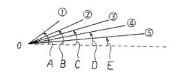
更に、図5は初期フレームにおける複数のポリゴンの表示をポリゴン面に対し、水平方向から観察した図である。複数のポリゴン▲1▼〜▲5▼が、水平軸に対し、順次角度が小さくなるような表示角度で表示されている。
【0045】
更に、上記図3及び図5に説明した表示ポリゴンの拡大、表示角度の変化を繰り返すことにより、動きのある飛沫状態を表示することが可能である。具体的に説明すると、図5に示されるそれぞれ角度A〜Eで表示されたポリゴン▲1▼〜▲5▼のそれぞれは、図5の状態から時間の経過とともにそれぞれ角度A〜Eより小さい角度で順次表示される。
【0046】
ここで、角度を小さくして表示されるポリゴンの大きさは、予め設定された角度に対応した大きさに第1のVDP41において演算される。このようにして、ポリゴン▲1▼からポリゴン▲5▼に向かってポリゴンが倒れ込むように表現できる。
【0047】
更に、図5に示すポリゴン▲1▼が角度を小さくしてポリゴン▲2▼の位置に表示される時、図5に示すポリゴン▲1▼の位置に新たなポリゴンが表示される。この時、図5に示すポリゴン▲5▼は、水平位置(図5の破線の水平軸)に移動して表示が消される。この様に繰り返すことにより、動きのある飛沫状態が表現される。
【0048】
図2に戻り説明すると、先ず、メインCPU2は、プログラム実行過程で、プログラムデータに基づき飛沫の表示が必要であるか否かを判断する(ステップS)。
【0049】
次いで、飛沫の表示が必要である場合は、表示座標、表示角度、初期・最終拡大率、表示フレーム数をプログラムデータに基づき第1のVDP41に付属するビデオRAM410に入力する(ステップS2)。ビデオRAM410は、したがって1フレーム中に変化する飛沫模様のパターンが貼り付けられているそれぞれのポリゴンの拡大率、角度を算出する(ステップS3)。
【0050】
ここで、1フレーム中に変化する飛沫模様のパターンが貼り付けられているそれぞれのポリゴンの拡大率、角度の算出の基礎となる前記表示座標、表示角度、及び初期・最終拡大率について説明する。
【0051】
図3において、図3(1)が初期の拡大率を有する飛沫模様のパターンが貼り付けられているポリゴンであり、頂点座標0〜3を有する。図3(5)が最終拡大率に拡大された飛沫模様のパターンが貼り付けられているポリゴンである。更に、前記表示座標及び表示角度は、図3(1)に示す初期拡大率のポリゴンの表示座標及び表示角度(図5▲1▼の角度A)である。
【0052】
更に、初期フレームにおける複数のポリゴンの表示をポリゴン面に対し水平方向から観察した図5において、▲1▼は表示角度Aを有する初期拡大率のポリゴンであり、▲5▼は表示角度Eを有する最終拡大率のポリゴンである。初期拡大率のポリゴンの表示座標と表示角度A、及びポリゴンの最終拡大率が与えられると、他のポリゴン▲2▼〜▲5▼の表示角度B〜E及び、ポリゴン▲2▼〜▲4▼の拡大率が計算できる。
【0053】
したがって、第1のVDP41は、これら1フレーム中に変化する拡大率・表示角度に基づいて計算をし、その計算結果のポリゴンデータを第2のVDP42に送り、第2のVDP42の処理により表示装置上に表示が行われる(ステップS4)。
【0054】
ここで、表示すべきフレーム数分の表示を行ない終了する(ステップS6)。またフレーム毎の拡大率及び角度の更新が必要であれば、更新された拡大率及び角度に基づき、ステップS3の処理を行なう(ステップS5)。
【0055】
図6は、この様にして表示制御される、スキーヤによって蹴り出される雪の飛沫の表示例である。特に、スキーヤによって蹴り出される雪の飛沫を表示するポリゴン面に対し、水平となる方向に視点を置いて観察される表示例である。
【0056】
図示されるように、かかるポリゴン面と水平になる方向に視点を置いて観察される場合であっても、本発明において、角度を変えて複数のポリゴンの表示が行われるので、飛沫の状態が一の線状とならず仮想現実感を損なうことがない。
【0057】
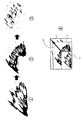
更に図7〜図9は、他の実施例であり、特にアニメーション像の駒を拡大率が変えられるポリゴン毎に対応して飛沫模様として貼り付けている例である。更に、図10〜図12は、図7〜図9に対応する拡大率と拡大方向の関係を示す実施の形態を示す図である。
【0058】
即ち、図7は、図7▲4▼に示す関係から、基準ポリゴンAを初期ポリゴンとして、矢印AAの方向に拡大し、図7▲2▼に示す中間拡大率のポリゴンBを表示し、次いで、図7▲3▼に示す、ポリゴンBより更に大きい拡大率のポリゴンCが表示される。この時、ポリゴンA、B、Cの飛沫模様は、図示されるようにアニメーションの駒の模様がそれぞれに貼り付けられる。
【0059】
ここで、ポリゴンは、図7▲4▼に示すように矢印AAの一方向に拡大するのみでなく、図10に示すように、最大拡大率の後、拡大率を下げることも可能である。
【0060】
即ち、図10において、基準ポリゴンAの拡大率を100%とすると、縦方向に230%の最大拡大率、横方向に200%の拡大率のポリゴン▲1▼とし、次いで、縦方向200%、横方向230%のポリゴン▲2▼とする。
【0061】
更に、縦方向に100%の拡大率、横方向に最大拡大率250%のポリゴン▲2▼とし、更に横方向に拡大すると共に縦方向に拡大率を小さくして消滅させる様に変化させている。
【0062】
図8は、アニメーションを用いた別の実施例であり、図8▲4▼に示すように、基準ポリゴンAを縦及び横方向に拡大したポリゴンBに変化させ、更に、ポリゴンBに対し、縦方向に拡大率を小さくし、横方向に拡大率を大きくしたポリゴンCに変化させる。
【0063】
図8▲1▼、▲2▼、▲3▼のそれぞれは、ポリゴンA,B,Cのそれぞれに対し貼り付けられる雪の飛沫柱のアニメーションの駒の模様である。したがって、ポリゴンA,B,Cの表示によって、雪の飛沫柱の画像が容易に表示可能である。
【0064】
図11は、図8に対応する、縦横の拡大率の関係を説明する図である。即ち、図8▲1▼のポリゴンを左右に拡大し、且つ上方向に拡大する関係を示している。尚、図11において、▲1▼、▲2▼、▲3▼の数字は、図8の▲1▼、▲2▼、▲3▼の画像の時のポリゴンの拡大率を示している。
【0065】
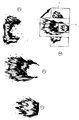
さらに、図9は、2つの種類のアニメーションの駒あるいはパターンの像をポリゴンに貼り付けた実施例である。この場合は、図9▲1▼、▲2▼の2つの種類のアニメーション像あるいはパターンの像が用意される。例えばキャラクタとしてスキーヤである場合、スキーヤの進行する後ろ側に図9▲3▼のような雪上の通過軌跡の模様を表示する場合である。
【0066】
図9▲3▼の実施例では、スキーヤの進行方向と逆方向に、図9▲1▼のパターンを順次に拡大率を大きくして表示し、図9▲1▼のパターンを所定個数、例えば5個表示した後、これらの表示が消される間際に図9▲2▼のパターンを表示している。これにより雪上にスキーヤの軌跡が現実感を持って表示できる。
【0067】
図12は、図9に対応するポリゴンの拡大率を示している。1つのポリゴンの1つの辺の中心座標を基準に、対称となるようにこの辺に沿う軸方向にその大きさの拡大率を順次変化して表示することを示している。尚、図12では、図示省略されているが、図9の実施例では当該1つの辺の垂直方向にも順次拡大している。
【0068】
以上の実施の形態では、専ら雪の飛沫について説明したが、本発明はこれに限定されず、水、粉体等の飛沫の画像をポリゴンにより表示する場合にも適用が容易である。
【0069】
【発明の効果】
以上実施の形態に従い説明したように、本発明により容易に雪、水等の飛沫の画像をポリゴンを用いて表示することが可能である。したがって、より現実感を与える飛沫の画像を有するゲーム等のプログラムの設計が容易になる。
【図面の簡単な説明】
【図1】本発明を適用する画像処理装置してのビデオゲーム装置の実施の形態例ブロック図である。
【図2】本発明の飛沫表示方法の一動作フローである。
【図3】本発明の原理を説明する図である。
【図4】本発明の原理を説明する図であり、更に複数の拡大されたポリゴンを重ねた状態を示す図である。
【図5】1フレームに表示される複数の拡大されたポリゴンと表示角度との関係を説明する図である。
【図6】スキーヤによって蹴り出される雪の飛沫の表示例である。
【図7】アニメーション像の駒を拡大率が変えられるポリゴン毎に対応して飛沫模様として貼り付けている例である。
【図8】飛沫柱のアニメーション像の駒を拡大率が変えられるポリゴン毎に対応して飛沫柱模様として貼り付けている例である。
【図9】2つの種類のアニメーションの駒の像をポリゴンに貼り付けた実施例である。
【図10】図7に対応してポリゴンの拡大率を変える例を説明する図である。
【図11】図8に対応してポリゴンの拡大率を変える例を説明する図である。
【図12】図9に対応してポリゴンの拡大率を変える例を説明する図である。
【図13】雪の飛沫を生成の例を示す図である。
【符号の説明】
100 ビデオゲーム装置本体
2 CPU
80 ROMカートリッジ
91 CD−ROMドライバ
30 入力パッド
40 表示装置
41、42 ビデオディスプレィプロセッサ[0001]
BACKGROUND OF THE INVENTION
The present invention relates to a splash display method in an image processing apparatus. In particular, the present invention relates to a method for displaying the state of splashes with polygons in a video game apparatus or the like that displays images with a plurality of polygons.
[0002]
[Prior art]
In a video game device or the like, an image is displayed with a plurality of polygons having three-dimensional spatial coordinates in order to give a player a virtual reality. For this reason, as the game progresses, polygon data having three-dimensional space coordinates are converted into two-dimensional coordinates corresponding to the display screen, and then textures such as texture are pasted on the polygons, and display is performed according to display priority. Is called.
[0003]
In such a case, when the splash state of the liquid or the splash state of the snow when the snow is kicked by skiing as shown in FIG. 13 is displayed by polygons, it is necessary to express by using a large number of small polygons. Furthermore, in order to express the state of change of the splash, high-speed processing is required for a plurality of polygons, and there is a problem that the load on the processing device increases.
[0004]
In response to such a problem, the present applicant has previously developed to express a water splash state or a mud splash state, that is, a mud splash state, by attaching a texture that expresses the splash to one polygon.
[0005]
[Problems to be solved by the invention]
However, when it is desired to display the state of the splash with one polygon to which the texture expressing the splash is pasted, the display image observed from a viewpoint close to the horizontal direction of the polygon surface is particularly a texture that expresses the splash. May be displayed as a single line. In such a case, virtual reality is particularly lacking.
[0006]
Accordingly, an object of the present invention is to provide a splash display method in an image processing apparatus that does not increase the load on the processing apparatus and at the same time does not impair virtual reality.
[0007]
It is another object of the present invention to provide a display method that can easily cope with various splash patterns.
[0008]
Another object of the present invention is to provide a splash display method that enables a splash pattern to be expressed using animation.
[0009]
Still another object of the present invention is to provide a display method that enables display of splashes in any image display software that requires expression of splashes, such as video game devices.
[0010]
A further object of the present invention is to provide a recording medium for storing a program for realizing the above method and an image processing apparatus using the recording medium.
[0011]
[Means for Solving the Problems]
A splash display method in an image processing apparatus according to the present invention that achieves the above-described problem and an image processing apparatus using the same are a plurality of polygons each having a texture that expresses a splash in an image display method that displays an image using a plurality of polygons. The splash state is displayed by displaying polygons at different angles.
[0012]
Further, the display angle of each of the plurality of polygons displayed at different angles is further reduced with time.
[0013]
Further, the size of the polygon displayed with the angle is made different according to the displayed angle.
[0014]
Furthermore, as a specific aspect of the present invention that achieves the above-described problem, a size of a single polygon with a texture that expresses the splash is determined in two axial directions with reference to one vertex coordinate of the single polygon. It is characterized in that the splash state is displayed by sequentially changing and displaying the enlargement ratio.
[0015]
Furthermore, as a specific aspect of the present invention that achieves the above-described problem, one polygon with a texture that expresses the splash is symmetric with respect to the coordinates of both ends of one side of the one polygon. It is also possible to display the splash state by sequentially changing the enlargement ratio of the size in the biaxial direction.
[0016]
In addition, with respect to one polygon with a texture that expresses splashes, the enlargement ratio of the size is sequentially increased in the axial direction along the side so as to be symmetric with respect to the center coordinates of one side of the one polygon. It is also possible to display the splash state by changing and displaying.
[0017]
Further, in any of the above, in synchronization with the enlargement ratio the sequentially changed, by displaying a different angle of the polygon, it is also possible to display a splash state.
[0018]
Furthermore, in the above, transparent color data is pasted to the pixels of the region other than the texture representing the splash of one polygon to which the texture representing the splash is pasted. Thereby, the splash of snow or water can be displayed.
[0019]
Further, the texture representing the splash is assigned to each of a plurality of frames constituting the animation image of the splash in accordance with the change in the sequential enlargement ratio of the one polygon.
[0020]
Further, the texture pattern expressing the splash may be assigned a different pattern corresponding to the change in the sequential enlargement ratio of the one polygon.
[0021]
DETAILED DESCRIPTION OF THE INVENTION
Embodiments of the present invention will be described below with reference to the drawings. In the drawings, the same or similar elements are described with the same reference numerals or reference symbols.
[0022]
FIG. 1 is a block diagram of an embodiment of a video game apparatus as an image processing apparatus to which the present invention is applied. In the figure, the
[0023]
The
[0024]
The
[0025]
The
[0026]
A
[0027]
Further, frame buffer memories (FB) 411 and 412 are connected to the
[0028]
The
[0029]
The
[0030]
The CPU control circuit 31 connected to the first bus (CPU-BUS) 5 is a first bus (CPU-BUS) when a pair of CPUs as the high-
[0031]
The CPU control circuit 31 controls the
[0032]
Furthermore, ROM cartridge 80 which is connected to the second bus (A-BUS) 8 is connected in a insertion to the outside of the
[0033]
Connected to the second bus (A-BUS) 8 through an optical disk control unit 9 are a functional block as an optional device for generating an external video signal such as a CD-
[0034]
The conversion circuit 401 is a circuit that converts an analog RGB signal that is an output from the
[0035]
A sound source processing circuit 7 is further connected to the third bus (B-BUS) 6 to control the sound generation of the PCM / FM sound source. The sound source processing circuit 7 is connected to a
[0036]
Further, a D /
[0037]
Next, features of the present invention implemented in the video game apparatus as shown in FIG. 1 will be described below.
[0038]
FIG. 2 is an operation flow of the splash display method of the present invention. The operation flow is executed by the
[0039]
Before describing the operation of FIG. 2, the embodiment of the present invention will be described with reference to FIGS. In FIG. 3, FIGS. 3 (1) to 3 (5) are diagrams in which one
[0040]
That is, in FIG. 3, the transparent texture is affixed to the polygon except for the area where the splash pattern is affixed. When the pattern of the splash pattern is a splash of snow, a texture expressing the splash of snow based on white is pasted. The texture data expressing the splash of snow based on the transparency or white color is read from the texture map stored in the RAM 33 or the like by the
[0041]
One polygon on which the splash pattern is pasted is enlarged in the order of FIGS. 3 (1) to (5) and displayed sequentially. Therefore, it is possible to display in a pseudo manner the state in which the splashes spread sequentially.
[0042]
FIG. 4 is a diagram in which one polygon on which a splash pattern is pasted in this way is sequentially enlarged, and the displayed state is observed from above, that is, from a direction perpendicular to the polygon surface. The state where the splash pattern spreads can be observed.
[0043]
In FIG. 4A, the shape of one polygon to which the splash pattern is attached is a rhombus. FIG. 4 (2) shows a case where the shape of the polygon to which the splash pattern is attached is a square. In either case, the axis is superimposed on one
[0044]
Further, FIG. 5 is a diagram in which the display of a plurality of polygons in the initial frame is observed from the horizontal direction with respect to the polygon surface. A plurality of polygons {1} to {circle around (5)} are displayed at display angles such that the angles are sequentially reduced with respect to the horizontal axis.
[0045]
Furthermore, by repeating the enlargement of the display polygon and the change of the display angle described in FIGS. 3 and 5 above, it is possible to display a moving splash state. More specifically, the polygons {circle around (1)} to {circle around (5)} shown at angles A to E shown in FIG. 5 are smaller than the angles A to E with the passage of time from the state of FIG. Displayed sequentially.
[0046]
Here, the size of the polygon displayed at a reduced angle is calculated in the
[0047]
Furthermore, when the polygon {circle around (1)} shown in FIG. 5 is displayed at the position of the polygon {circle around (2)} with a smaller angle, a new polygon is displayed at the position of the polygon {circle around (1)} shown in FIG. At this time, the polygon (5) shown in FIG. 5 is moved to the horizontal position (the horizontal axis of the broken line in FIG. 5) and the display is turned off. By repeating in this way, a moving splash state is expressed.
[0048]
Referring back to FIG. 2, first, the
[0049]
Next, when it is necessary to display the splash, the display coordinates, the display angle, the initial / final enlargement ratio, and the number of display frames are input to the
[0050]
Here, the enlargement ratio, the display coordinates, the display angle, and the initial / final enlargement ratio, which are the basis for calculating the angle, of each polygon to which a splash pattern that changes in one frame is attached will be described.
[0051]
In FIG. 3, FIG. 3A is a polygon to which a splash pattern having an initial enlargement ratio is pasted, and has vertex coordinates 0 to 3. FIG. 3 (5) shows a polygon to which a splash pattern that has been enlarged to the final enlargement rate is pasted. Further, the display coordinates and the display angle are the display coordinates and the display angle (angle A in FIG. 5 (1)) of the polygon having the initial magnification shown in FIG.
[0052]
Further, in FIG. 5 in which the display of a plurality of polygons in the initial frame is observed from the horizontal direction with respect to the polygon surface, {circle over (1)} is a polygon with an initial magnification having a display angle A, and {circle over (5)} has a display angle E. This is the final magnification polygon. Given the display coordinates and display angle A of the polygon with the initial enlargement ratio, and the final enlargement ratio of the polygon, the display angles B to E of the other polygons (2) to (5) and the polygons (2) to (4) The enlargement ratio can be calculated.
[0053]
Therefore, the
[0054]
Here, display is performed for the number of frames to be displayed, and the process ends (step S6). If it is necessary to update the enlargement factor and angle for each frame, the process of step S3 is performed based on the updated enlargement factor and angle (step S5).
[0055]
FIG. 6 is a display example of the splash of snow kicked out by the skier, the display of which is controlled in this way. In particular, it is a display example that is observed with a viewpoint in a horizontal direction with respect to a polygonal surface that displays a splash of snow kicked out by a skier.
[0056]
As shown in the drawing, even when the image is observed with the viewpoint in a direction horizontal to the polygon surface, in the present invention, since a plurality of polygons are displayed at different angles, the state of the splash is It does not become one line and does not impair virtual reality.
[0057]
Further, FIGS. 7 to 9 show other embodiments, in particular, an example in which a frame of an animation image is pasted as a splash pattern corresponding to each polygon whose magnification rate can be changed. Further, FIGS. 10 to 12 are diagrams showing an embodiment showing a relationship between an enlargement ratio and an enlargement direction corresponding to FIGS. 7 to 9.
[0058]
That is, FIG. 7 uses the relationship shown in FIG. 7 (4) as a reference polygon A as an initial polygon, enlarges in the direction of arrow AA, displays a polygon B having an intermediate enlargement ratio shown in FIG. 7C, a polygon C having a larger enlargement ratio than that of the polygon B is displayed. At this time, the splash pattern of the polygons A, B, and C is pasted to the animation frame pattern as shown in the figure.
[0059]
Here, the polygon is not only enlarged in one direction of the arrow AA as shown in FIG. 7 (4), but the enlargement rate can be lowered after the maximum enlargement rate as shown in FIG.
[0060]
That is, in FIG. 10, assuming that the enlargement ratio of the reference polygon A is 100%, the maximum enlargement ratio is 230% in the vertical direction and the polygon {circle around (1)} is 200% in the horizontal direction. The polygon is 230% in the horizontal direction (2).
[0061]
Furthermore, the polygon (2) has an enlargement ratio of 100% in the vertical direction and a maximum enlargement ratio of 250% in the horizontal direction. The polygon is further expanded in the horizontal direction and reduced in the vertical direction to disappear. .
[0062]
FIG. 8 shows another embodiment using animation. As shown in FIG. 8 (4), the reference polygon A is changed to a polygon B expanded in the vertical and horizontal directions, and further, The polygon C is changed to a polygon C having a smaller enlargement ratio in the direction and a larger enlargement ratio in the horizontal direction.
[0063]
Each of FIGS. 8 (1), (2), and (3) is a pattern of an animation piece of a snow splash column attached to each of polygons A, B, and C. Therefore, by displaying the polygons A, B, and C, it is possible to easily display an image of a snow splash column.
[0064]
FIG. 11 is a diagram for explaining the relationship between the vertical and horizontal enlargement ratios corresponding to FIG. That is, FIG. 8 (1) shows a relationship in which the polygon is enlarged to the left and right and enlarged upward. In FIG. 11, the numbers {circle around (1)}, {circle around (2)}, and {circle around (3)} indicate the enlargement ratio of the polygon for the images {circle around (1)}, {circle around (2)}, and {circle around (3)} in FIG.
[0065]
Further, FIG. 9 shows an embodiment in which two types of animation pieces or pattern images are pasted on a polygon. In this case, two types of animation images or pattern images shown in FIGS. 9 (1) and (2) are prepared. For example, in the case of a skier as a character, a pattern of a passing locus on snow as shown in FIG.
[0066]
In the embodiment shown in FIG. 9 (3), the pattern shown in FIG. 9 (1) is displayed in the direction opposite to the direction of the skier and the enlargement ratio is sequentially increased, and a predetermined number of patterns such as FIG. After displaying five, the pattern of FIG. 9 (2) is displayed just before these displays are erased. As a result, the trajectory of the skier can be displayed on the snow with a sense of reality.
[0067]
FIG. 12 shows the enlargement ratio of the polygon corresponding to FIG. This shows that the magnification is sequentially changed and displayed in the axial direction along this side so as to be symmetric with respect to the center coordinates of one side of one polygon. Although not shown in FIG. 12, in the embodiment of FIG. 9, the one side is also enlarged in the vertical direction.
[0068]
In the above embodiment, the description has been made only on the splash of snow. However, the present invention is not limited to this, and can be easily applied to the case where an image of splash of water, powder, or the like is displayed with polygons.
[0069]
【The invention's effect】
As described above according to the embodiment, the present invention can easily display an image of splashes of snow, water, etc. using polygons. Therefore, it is easy to design a program such as a game having a splash image that gives a more realistic feeling.
[Brief description of the drawings]
FIG. 1 is a block diagram of an embodiment of a video game apparatus as an image processing apparatus to which the present invention is applied.
FIG. 2 is an operation flow of the splash display method of the present invention.
FIG. 3 is a diagram illustrating the principle of the present invention.
FIG. 4 is a diagram for explaining the principle of the present invention, and further showing a state in which a plurality of enlarged polygons are superposed.
FIG. 5 is a diagram illustrating a relationship between a plurality of enlarged polygons displayed in one frame and a display angle.
FIG. 6 is a display example of a splash of snow kicked out by a skier.
FIG. 7 is an example in which a frame of an animation image is pasted as a splash pattern corresponding to each polygon whose magnification rate can be changed.
FIG. 8 is an example in which a frame of an animation image of a splash column is pasted as a splash column pattern corresponding to each polygon whose magnification rate can be changed.
FIG. 9 is an example in which images of two types of animation frames are pasted on a polygon.
10 is a diagram for explaining an example of changing a magnification rate of a polygon in correspondence with FIG. 7; FIG.
FIG. 11 is a diagram for explaining an example of changing the enlargement ratio of a polygon corresponding to FIG. 8;
12 is a diagram for explaining an example of changing the enlargement ratio of a polygon corresponding to FIG. 9; FIG.
FIG. 13 is a diagram illustrating an example of generation of snow splashes.
[Explanation of symbols]
100 Video
80
Claims (9)
前記制御手段による前記プログラムの実行により,
2軸を含む平面をポリゴン面として備えた基準ポリゴンに対し,順次拡大率がそれぞれ異なる複数のポリゴンを生成し,
前記生成された複数のポリゴンのそれぞれに飛沫を表現するテクスチャを貼り,
前記テクスチャが貼られた複数のポリゴンが,前記基準ポリゴンの前記2軸を含む平面と,それぞれ異なる角度をなして表示され,更に前記複数のポリゴンのそれぞれがなす角度が,時間の経過とともに小さくなるようにして表示される画像を生成し,
前記生成された画像を前記ディスプレー装置に表示する
ことを特徴とする飛沫表示方法。A splash display method in an image processing apparatus for displaying an image formed by a plurality of polygons on a display device based on control of a control means for executing a program,
By executing the program by the control means,
A plurality of polygons with different enlargement ratios are sequentially generated for a reference polygon having a plane including two axes as a polygon surface.
A texture representing splash is pasted on each of the generated polygons,
The plurality of polygons to which the texture is pasted are displayed at different angles from the plane including the two axes of the reference polygon, and the angle formed by each of the plurality of polygons decreases with time. To generate the displayed image,
The splash display method, wherein the generated image is displayed on the display device.
前記角度を持って表示されるポリゴンの大きさを,前記表示される角度に対応して異なるものとしたことを特徴とする飛沫表示方法。In claim 1,
A splash display method, wherein a size of a polygon displayed with the angle is made different according to the displayed angle.
前記制御手段による前記プログラムの実行により,
2軸を含む平面をポリゴン面として備えた基準ポリゴンに対し,順次拡大率がそれぞれ異なる複数のポリゴンを生成し,
前記生成された複数のポリゴンのそれぞれに飛沫を表現するテクスチャを貼り,
前記テクスチャが貼られた複数のポリゴンが,前記基準ポリゴンの前記2軸を含む平面と,それぞれ異なる角度をなして表示される画像を生成し,
前記生成された画像を前記ディスプレー装置に表示し,
前記それぞれ飛沫を表現するテクスチャを貼った複数のポリゴンは,前記基準ポリゴンの一つの頂点座標を基準に,2軸方向にその大きさの拡大率を順次変化して表示されるものである
ことを特徴とする画像処理装置における飛沫表示方法。A splash display method in an image processing apparatus for displaying an image formed by a plurality of polygons on a display device based on control of a control means for executing a program,
By executing the program by the control means,
A plurality of polygons with different enlargement ratios are sequentially generated for a reference polygon having a plane including two axes as a polygon surface.
A texture representing splash is pasted on each of the generated polygons,
A plurality of polygons to which the texture is pasted generate an image displayed at a different angle from a plane including the two axes of the reference polygon;
Displaying the generated image on the display device;
The plurality of polygons to which the texture representing each splash is pasted are displayed by sequentially changing the enlargement ratio of the sizes in the two-axis directions with reference to one vertex coordinate of the reference polygon. A splash display method in an image processing apparatus.
前記制御手段による前記プログラムの実行により,
2軸を含む平面をポリゴン面として備えた基準ポリゴンに対し,順次拡大率が異なる複数のポリゴンを生成し,
前記生成された複数のポリゴンにそれぞれ飛沫を表現するテクスチャを貼り,アニメーション画像として,前記ディスプレー装置に表示し,
前記複数のポリゴンは,前記基準ポリゴンの一つの辺の中心座標を基準に,対称となるように前記一の辺に沿う軸方向に拡大率がそれぞれ異なり,且つ前記一の辺に垂直な方向に拡大率がそれぞれ異なるように,順次変化して表示されるものであることを特徴とする画像処理装置における飛沫表示方法。 A splash display method in an image processing apparatus for displaying an image formed by a plurality of polygons on a display device based on control of a control means for executing a program,
By executing the program by the control means,
A plurality of polygons with different enlargement ratios are sequentially generated for a reference polygon having a plane including two axes as a polygon surface.
A texture representing splash is pasted on each of the generated polygons, and an animation image is displayed on the display device.
The plurality of polygons have different enlargement ratios in the axial direction along the one side so as to be symmetric with respect to the center coordinates of one side of the reference polygon, and in a direction perpendicular to the one side. A splash display method in an image processing apparatus, wherein the display is sequentially changed so that the enlargement ratios are different.
前記制御手段による前記プログラムの実行により,
2軸を含む平面をポリゴン面として備えた基準ポリゴンに対し,順次拡大率がそれぞれ異なる複数のポリゴンを生成し,
前記生成された複数のポリゴンのそれぞれに飛沫を表現するテクスチャを貼り,
前記テクスチャが貼られた複数のポリゴンが,前記基準ポリゴンの前記2軸を含む平面と,それぞれ異なる角度をなして表示される画像を生成し,
前記生成された画像を前記ディスプレー装置に表示し,
前記それぞれ飛沫を表現するテクスチャを貼った複数のポリゴンは,前記基準ポリゴンの一の辺の中心座標を基準に,対称となるように前記一の辺に沿う軸方向にその大きさの拡大率を順次変化して表示されるものである
ことを特徴とする画像処理装置における飛沫表示方法。A splash display method in an image processing apparatus for displaying an image formed by a plurality of polygons on a display device based on control of a control means for executing a program,
By executing the program by the control means,
A plurality of polygons with different enlargement ratios are sequentially generated for a reference polygon having a plane including two axes as a polygon surface.
A texture representing splash is pasted on each of the generated polygons,
A plurality of polygons to which the texture is pasted generate an image displayed at a different angle from a plane including the two axes of the reference polygon;
Displaying the generated image on the display device;
Each of the plurality of polygons with a texture expressing each splash has an enlargement ratio of its size in the axial direction along the one side so as to be symmetric with respect to the center coordinates of one side of the reference polygon. A splash display method in an image processing apparatus, characterized in that the display is sequentially changed.
更に前記順次変化する拡大率に同期して,前記ポリゴンの角度を変えて表示することにより,前記角度を異ならして表示することを特徴とする画像処理装置における飛沫表示方法。In any of claims 3 to 5,
Further, the splash display method in the image processing apparatus, wherein the polygons are displayed at different angles by changing the angles of the polygons in synchronization with the sequentially changing magnification.
前記飛沫を表現するテクスチャは,前記ポリゴンの順次の拡大率の変化に対応して,飛沫のアニメーション画像を構成する複数の駒のそれぞれが割り当てられることを特徴とする飛沫表示方法。In claim 6,
The splash display method, wherein the texture representing the splash is assigned to each of a plurality of frames constituting an animation image of the splash in response to a change in the sequential enlargement ratio of the polygon.
前記制御手段による前記プログラムの実行により,
2軸を含む平面をポリゴン面として備えた基準ポリゴンの一の辺の中心座標を基準に,対称となるように前記一の辺に沿う軸方向に順次拡大率がそれぞれ異なる複数のポリゴンを生成し,
前記生成された複数のポリゴンのそれぞれに飛沫を表現するテクスチャを貼り,
前記テクスチャが貼られた複数のポリゴンが,前記キャラクタの後側に前記キャラクタの進行方向と逆方向に順次に前記拡大率を大きくして表示される画像を生成し,
前記生成された画像を前記ディスプレー装置に表示する
ことを特徴とする飛沫表示方法。A splash display method in an image processing device that displays a running image of a character on a display device, which is formed by a plurality of polygons based on control of a control means that executes a program,
By executing the program by the control means,
A plurality of polygons having different enlargement ratios sequentially in the axial direction along the one side are generated so as to be symmetric with respect to the center coordinates of one side of the reference polygon having a plane including two axes as a polygon surface. ,
A texture representing splash is pasted on each of the generated polygons,
A plurality of polygons to which the texture is pasted generate an image that is displayed on the rear side of the character with the enlargement ratio sequentially increased in the direction opposite to the character traveling direction,
A splash display method, comprising: displaying the generated image on the display device.
Priority Applications (1)
| Application Number | Priority Date | Filing Date | Title |
|---|---|---|---|
| JP16217197A JP3978812B2 (en) | 1997-06-19 | 1997-06-19 | Splash display method in image processing apparatus |
Applications Claiming Priority (1)
| Application Number | Priority Date | Filing Date | Title |
|---|---|---|---|
| JP16217197A JP3978812B2 (en) | 1997-06-19 | 1997-06-19 | Splash display method in image processing apparatus |
Publications (2)
| Publication Number | Publication Date |
|---|---|
| JPH117547A JPH117547A (en) | 1999-01-12 |
| JP3978812B2 true JP3978812B2 (en) | 2007-09-19 |
Family
ID=15749378
Family Applications (1)
| Application Number | Title | Priority Date | Filing Date |
|---|---|---|---|
| JP16217197A Expired - Lifetime JP3978812B2 (en) | 1997-06-19 | 1997-06-19 | Splash display method in image processing apparatus |
Country Status (1)
| Country | Link |
|---|---|
| JP (1) | JP3978812B2 (en) |
Families Citing this family (2)
| Publication number | Priority date | Publication date | Assignee | Title |
|---|---|---|---|---|
| JP3816375B2 (en) | 2001-11-15 | 2006-08-30 | 株式会社スクウェア・エニックス | VIDEO GAME DEVICE, CHARACTER DISPLAY METHOD, PROGRAM, AND RECORDING MEDIUM FOR VIDEO GAME |
| JP2010079564A (en) * | 2008-09-25 | 2010-04-08 | Namco Bandai Games Inc | Program, information storage medium and game apparatus |
-
1997
- 1997-06-19 JP JP16217197A patent/JP3978812B2/en not_active Expired - Lifetime
Also Published As
| Publication number | Publication date |
|---|---|
| JPH117547A (en) | 1999-01-12 |
Similar Documents
| Publication | Publication Date | Title |
|---|---|---|
| EP0620532B1 (en) | Method and apparatus for synthesizing a three-dimensional image signal and producing a two-dimensional visual display therefrom | |
| JP2006068138A (en) | Game apparatus and image processing program | |
| JPH09319891A (en) | Image processor and its processing method | |
| EP1126416B1 (en) | Randomly animating a flame in an image | |
| JP2000011204A (en) | Image processing method and recording medium with image processing program recorded thereon | |
| EP1312047B1 (en) | Apparatus and method for rendering antialiased image | |
| US6339430B1 (en) | Video game machine and method for changing texture of models | |
| JP4305903B2 (en) | Image generation system, program, and information storage medium | |
| JP3748451B1 (en) | Program, information storage medium, and image generation system | |
| JP4749198B2 (en) | Program, information storage medium, and image generation system | |
| JP3978812B2 (en) | Splash display method in image processing apparatus | |
| JPH1139502A (en) | Device and method for displaying image and recording medium | |
| JP2000218036A (en) | Game device, game control method and recording medium therefor | |
| JP5146054B2 (en) | Generation control program of sound generated from sound source in virtual space | |
| JP4106917B2 (en) | Animation generation program and image processing apparatus using the same | |
| JP4592087B2 (en) | Image generation system, program, and information storage medium | |
| JP2004038398A (en) | Program and method for three-dimensional image processing, and video game device | |
| JP3468985B2 (en) | Graphic drawing apparatus and graphic drawing method | |
| JP4688405B2 (en) | PROGRAM, INFORMATION STORAGE MEDIUM, AND GAME DEVICE | |
| JP2003067770A (en) | Image generating device and image generating program | |
| JP3867071B2 (en) | Image processing apparatus and image processing method | |
| JP2008077406A (en) | Image generation system, program, and information storage medium | |
| JP2007164736A (en) | Image generation system, program and information storage medium | |
| JP3990543B2 (en) | Program, information storage medium, and game device | |
| JPH0744735A (en) | Picture processor |
Legal Events
| Date | Code | Title | Description |
|---|---|---|---|
| A521 | Written amendment |
Free format text: JAPANESE INTERMEDIATE CODE: A523 Effective date: 20040615 |
|
| A621 | Written request for application examination |
Free format text: JAPANESE INTERMEDIATE CODE: A621 Effective date: 20040615 |
|
| A977 | Report on retrieval |
Free format text: JAPANESE INTERMEDIATE CODE: A971007 Effective date: 20070112 |
|
| A131 | Notification of reasons for refusal |
Free format text: JAPANESE INTERMEDIATE CODE: A131 Effective date: 20070123 |
|
| A521 | Written amendment |
Free format text: JAPANESE INTERMEDIATE CODE: A523 Effective date: 20070309 |
|
| A131 | Notification of reasons for refusal |
Free format text: JAPANESE INTERMEDIATE CODE: A131 Effective date: 20070403 |
|
| A521 | Written amendment |
Free format text: JAPANESE INTERMEDIATE CODE: A523 Effective date: 20070510 |
|
| TRDD | Decision of grant or rejection written | ||
| A01 | Written decision to grant a patent or to grant a registration (utility model) |
Free format text: JAPANESE INTERMEDIATE CODE: A01 Effective date: 20070605 |
|
| A61 | First payment of annual fees (during grant procedure) |
Free format text: JAPANESE INTERMEDIATE CODE: A61 Effective date: 20070618 |
|
| R150 | Certificate of patent or registration of utility model |
Free format text: JAPANESE INTERMEDIATE CODE: R150 |
|
| FPAY | Renewal fee payment (event date is renewal date of database) |
Free format text: PAYMENT UNTIL: 20100706 Year of fee payment: 3 |