JP3977531B2 - Spout bag feeder - Google Patents
Spout bag feeder Download PDFInfo
- Publication number
- JP3977531B2 JP3977531B2 JP33971798A JP33971798A JP3977531B2 JP 3977531 B2 JP3977531 B2 JP 3977531B2 JP 33971798 A JP33971798 A JP 33971798A JP 33971798 A JP33971798 A JP 33971798A JP 3977531 B2 JP3977531 B2 JP 3977531B2
- Authority
- JP
- Japan
- Prior art keywords
- spout
- bag
- belt
- supply
- spout bag
- Prior art date
- Legal status (The legal status is an assumption and is not a legal conclusion. Google has not performed a legal analysis and makes no representation as to the accuracy of the status listed.)
- Expired - Lifetime
Links
Images


Description
【0001】
【発明の属する技術分野】
本発明は、キャップ形式の注ぎ口を有するいわゆるスパウト袋を一枚ずつ包装機側に自動的に送り込むための供給装置に関する。
【0002】
【従来の技術】
従来、キャップ形式の注ぎ口を有してその反対側を未溶封の開口部とされたスパウト袋は、注ぎ口部分が大きくて整列して移送させることが非常に困難であることから、専用の供給装置により包装機に自動供給する方法は採用されていなかった。
因に、スパウト袋を使用する包装機においては、注ぎ口部分を設けていない平坦な袋本体のみを供給装置によって包装機側に送り、ついで、包装機の特定工程において、その袋本体に別途供給部から送られた注ぎ口をセットしてから両者を溶封し一体化するという方法等が講じられている。
また、チャック付袋やスタンドパック袋については自動供給装置が使用されているが、これらの袋とスパウト袋の何れも包装機に自動的に供給することが可能な供給装置は開発されていないようである。
【0003】
【発明が解決しようとする課題】
スパウト袋を包装機に自動供給することができる供給装置があれば、包装機にスパウト袋を製造する機構部分が不要になって包装機全体の構造が簡素化される。しかも、スパウト袋でない通常の包装袋を使用する標準的な包装機について、スパウト袋の供給装置を設置することによりスパウト袋による包装が可能となるということから、かかるスパウト袋を包装機側に自動的に供給する供給装置の開発が要望されていた。
【0004】
この発明の目的は、スパウト袋を先端を揃えて一枚ずつ包装機側に自動的に送り込むための供給装置を提供することにある。
【0005】
【課題を解決するための手段】
前記目的を達成するために請求項1に記載した発明は、注ぎ口部を上にしてその反対側の未溶封の開口部を下にした多数のスパウト袋を第1モータ装置により駆動されるベルトコンベア上に倒し重ねて供給するストッカー部と、該ベルトコンベア上に設けられたフレームに、後部上方に配置した第1プーリと前部下方に配置した第2プーリに掛け渡した繰出ベルトを第2モータ装置により駆動するように設けて、その第2プーリの下面を前記ベルトコンベアの上面に対して駆動手段により上下方向に移動自在に設けた繰出ユニットと、前方の供給端に送られる先頭のスパウト袋の注ぎ口部に向けて圧縮空気を吹き出す第1ノズル及び後続のスパウト袋の注ぎ口部に向けて圧力空気を吹き出す第2ノズルとを設け、前記繰出ユニットの繰出ベルトを前記ベルトコンベアの送りベルトより早送り制御して先頭のスパウト袋を後続のスパウト袋から分離させて、供給端の袋ストッパーに同スパウト袋の開口部の先端が当接するまで送るように設け、前記第2プーリが上昇位置にあるときに、その供給端に送り込まれたスパウト袋の開口部側を、吸盤により吸着して受け渡し位置まで持ち上げる第1揺動レバーと、その第1揺動レバーにより持ち上げられたスパウト袋を吸盤により吸着して包装機への供給位置に設けられた挟着片対間に開口部を上位置にして供給する第2揺動レバーを設けたことを特徴とするものである。
【0006】
【発明の作用及び効果】
(1)多数のスパウト袋を注ぎ口部を上にしてその反対側の未溶封の開口部を下にしてストッカー部のベルトコンベア上に倒し重ねて供給する。それらのスパウト袋は緩速度でベルトコンベアにより前方に移送され、繰出ユニットの第2プーリの位置まで送られると、ベルトコンベアの送りベルトより早送り制御された繰出ベルトによって後続のスパウト袋から分離され、その先端が前方の供給端の袋ストッパーに当接する位置まで移送される。
(2)スパウト袋が袋ストッパーに当接して停止すると、繰出ユニットの繰出ベルトの送りが停止して第2プーリを駆動手段により上昇させると共に、その袋が後戻りしないようにその位置を保持するべく、第1ノズルから同スパウト袋の注ぎ口部に向けて圧縮空気が吹き出される。
(3)ついで、そのスパウト袋の開口部側が第1揺動レバーの吸盤により吸着されて受け渡し位置(I)まで持ち上げられ、これを第2揺動レバーの吸盤により吸着して受け取り、同レバーの上昇回転移動により開口部を上位置にされたスパウト袋が、包装機への供給位置(II)に設けられた挟着片対間に供給される。
(4)しかして、先頭のスパウト袋が第2揺動レバー側に受け渡されると、第1ノズルの圧縮空気の吹き出しが停止し、ベルトコンベアによる後続のスパウト袋の移送を補助するために、第2ノズルからそれらのスパウト袋に向けて圧縮空気が一定時間だけ吹き出される。次のスパウト袋が、繰出ユニットの下降した第2プーリの位置まで送られると、引き続き上記(1)〜(3)の動作が同様に行われて、スパウト袋は包装機側に連続的に供給される。
【0007】
このスパウト袋の供給装置は、スパウト袋を一枚ずつ包装機側の挟着片対間に安定して自動的に送り込むことができる。よって、従来より懸案とされていたスパウト袋を包装機に自動供給することが可能となったことにより、スパウト袋を用いる包装作業に大いに寄与する。
【0008】
【発明の実施の形態】
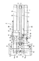
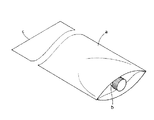
以下に、本発明の実施の形態例を図面に基づいて説明する。図1は供給装置の側面図、図2は同、平面図、図3は繰出ユニットとベルトコンベアとの関係を示す側面図、図4はスパウト袋の斜視図である。
【0009】
図1に示すスパウト袋の供給装置Pにおいて、11は図4に示すスパウト袋aを注ぎ口部bを上にしてその反対側の未溶封の開口部cを下にし、これを多数重ねて供給するストッカー部10を設けたベルトコンベアである。そのベルトコンベア11は、機台1の前端寄りと後端位置に2列のベルト溝を形成したプーリ12、13を回転自由に軸支し、上方送行部を機台1上に露出させた丸断面形状の送りベルト14をそれらのプーリ12、13に掛け渡し、前記機台1の底部に取り付けた第1モータ装置15により一方のプーリ12を緩速で回転駆動するように設けられている。16、17はスパウト袋aの両側を案内するために、機台1上に設けられた一対の案内板であり、それらの間隔をスパウト袋aの幅寸法の大きさに応じて調整自由に設ける。また、このベルトコンベア11の搬送面は、前方の供給端16a、17aに向かってやや下がり傾斜に設けられている。
【0010】
図2に示すように、案内板16、17の前方の供給端16a、17aには内方に突出する袋ストッパー18、19を取り付け、一方の袋ストッパー18側には、送り込まれたスパウト袋aの先端を接触させる検知レバー20を揺動可能に支持する。その検知レバー20を感知する近接センサー21は、スパウト袋aの確認と、スパウト袋を検知しないときに後記吸盤52の真空吸引作用を司る制御弁を停止作動させるものである。
【0011】
上記ベルトコンベア11の上方には、前記機台1の外側面に夫々固定されたガイドバー26にフレーム27を摺動可能に支持させた繰出ユニット25を設ける。この繰出ユニット25のフレーム27に軸支された回転軸28には、2列のベルト溝を設けた第1プーリ29を取り付け、該回転軸28を前記フレーム27に取り付けた第2モータ装置30でベルト31を介して駆動するように設ける。
前記回転軸28には第1プーリ29を挟んでアーム33及びほぼL字形のレバー34を回転可能に軸支し、それらの先端に第2プーリ35を回転自由に設ける。36は後部上方に配置した前記第1プーリ29と前部下方に配置した第2プーリ35に掛け渡した丸断面形状の繰出ベルトである。また、前記第2プーリ35の両端部にはリング状のベルト37、37を夫々装着する。
【0012】
前記フレーム27の内方に取り付けたブラケット40には、駆動手段たるエアーシリンダ41を設け、該エアーシリンダ41のロッドの先端部42を前記レバー34の短いレバー片34aの自由端に連結する。しかして、そのエアーシリンダ41によって前記第2プーリ35の下面をベルトコンベア11の上面に対して上下方向に一定の高さを移動自在に設ける。
【0013】
上記した繰出ユニット25は、繰出ベルト36をベルトコンベア11の送りベルト14より早送り制御することにより、前方のスパウト袋aを後続のスパウト袋aから分離させるように設けると共に、前方のスパウト袋aが袋ストッパー18、19に当接して停止した場合に、その繰出ベルト36の送りを停止し第2プーリ35をエアーシリンダ41により上昇移動させるように構成されている。
【0014】
42は前記フレーム27の内方に固定された支持枠43に設けられた第1ノズルであって、この第1ノズル42から前方の供給端16a、17aに送られた先頭のスパウト袋aの注ぎ口部bに向けて圧縮空気を吹き出し、該袋aが後戻りしないようにその位置を保持するべく設けられている。44は後続のスパウト袋aの注ぎ口部に向けて圧力空気を吹き出し、前記ベルトコンベア11によるスパウト袋aの移送を補助するように設けられた第2ノズルである。この第2ノズル44も第1ノズル42と同様に、前記支持枠43に取り付けられている。45は前記支持枠43に取り付けられた押えガイドであって、スパウト袋aの注ぎ口部bより少し上方に配置されている。
【0015】
図1、図2に示すように、51は包装機に設けられたスタンド50に揺動可能に支持された第1揺動レバーである。この第1揺動レバー51は、上記繰出ユニット25により送られて袋ストッパー18、19に当接したスパウト袋aを吸盤52により吸着し、これを受け渡し位置(I)まで持ち上げるように設けられている。
また、55は前記スタンド50に設けた回転軸56で揺動可能に支持されて、受け渡し位置(I)と包装機への供給位置(II)との間を可逆回転移動されるように設けられた第2揺動レバーである。この第2揺動レバー55は、その先端に設けた吸盤57により第1揺動レバー51で持ち上げられたスパウト袋aを吸着して、供給位置(II)に設けた挟着片対58間に供給するように設けられている。
なお、かかる第1揺動レバー51、第2揺動レバー55及び挟着片対58については、特公平6−55604号公報等で公知とされたものと同様の構造である。gは一般的なロータリー式包装機のグリップ対を示す。
【0016】
上記したスパウト袋の供給装置Pの作動については、上述した発明の作用の項、各構成要素の中で述べているのでその説明を省略する。
以上、このスパウト袋の供給装置によれば、従来装置で供給が困難とされていたスパウト袋を一枚ずつ包装機側に安定して自動的に送り込むことが可能となった。加えて、この供給装置によれば、チャック付袋やスタンドパック袋についても包装機に自動的に供給することが可能であるため、大変利便性がよい。
【図面の簡単な説明】
【図1】供給装置の側面図
【図2】同、平面図
【図3】繰出ユニットとベルトコンベアとの関係を示す側面図
【図4】スパウト袋の斜視図
【符号の説明】
P→スパウト袋の供給装置 (I)→受け渡し位置 (II)→包装機への供給位置
a→スパウト袋 b→注ぎ口部 c→開口部
10→ストッカー部 11→ベルトコンベア 16a、17a→供給端
18、19→袋ストッパー 25→繰出ユニット 27→フレーム
29→第1プーリ 30→第2モータ装置 35→第2プーリ
36→繰出ベルト 41→エアーシリンダ(駆動手段) 42→第1ノズル
44→第2ノズル 51→第1揺動レバー 52→吸盤
55→第2揺動レバー 57→吸盤 58→挟着片対[0001]
BACKGROUND OF THE INVENTION
The present invention relates to a supply device for automatically feeding so-called spout bags having cap-type spouts one by one to the packaging machine side.
[0002]
[Prior art]
Conventionally, a spout bag having a cap-type spout and having an unsealed opening on the opposite side is very difficult because the spout portion is large and very difficult to be aligned and transported. The automatic feeding method to the packaging machine by the feeding device was not adopted.
By the way, in a packaging machine that uses spout bags, only the flat bag body without the spout portion is sent to the packaging machine side by the supply device, and then supplied separately to the bag body in the specific process of the packaging machine. The method of sealing and integrating both after setting the pouring spout sent from the part is taken.
In addition, although automatic supply devices are used for bags with chucks and stand pack bags, no supply device has been developed that can automatically supply these bags and spout bags to a packaging machine. It is.
[0003]
[Problems to be solved by the invention]
If there is a supply device that can automatically supply the spout bag to the packaging machine, the mechanism part for manufacturing the spout bag in the packaging machine becomes unnecessary, and the structure of the entire packaging machine is simplified. Moreover, for standard packaging machines that use normal packaging bags that are not spout bags, it is possible to wrap with spout bags by installing a spout bag supply device. There was a need to develop a supply device that could be supplied in an automated manner.
[0004]
An object of the present invention is to provide a supply device for automatically feeding spout bags one by one with their tips aligned to the packaging machine side one by one.
[0005]
[Means for Solving the Problems]
In order to achieve the above object, according to the first aspect of the present invention, the first motor device drives a large number of spout bags with the spout portion up and the unsealed opening on the opposite side down. A stocker unit that is fed over the belt conveyer and a frame provided on the belt conveyer is provided with a first belt disposed above the rear portion and a second belt disposed on the second pulley disposed below the front portion. A feeding unit provided to be driven by a two-motor device, the lower surface of the second pulley being movable in the vertical direction by the driving means with respect to the upper surface of the belt conveyor, and a leading unit sent to the front supply end A first nozzle that blows out compressed air toward the spout of the spout bag and a second nozzle that blows out pressurized air toward the spout of the subsequent spout bag; Is provided so that the leading spout bag is separated from the succeeding spout bag by feeding it faster than the feed belt of the belt conveyor, and is sent until the tip of the opening of the spout bag comes into contact with the bag stopper at the supply end, When the second pulley is in the raised position, the opening portion of the spout bag fed to the supply end is lifted by the first swing lever, which is sucked up by the suction cup to the delivery position, and the first swing lever A second rocking lever is provided that sucks the spout bag that is sucked by a suction cup and supplies the spout bag with the opening positioned between the pair of sandwiching pieces provided at the supply position to the packaging machine. is there.
[0006]
[Action and effect of the invention]
(1) A large number of spout bags are supplied while being sprinkled on the belt conveyor of the stocker section with the spout portion facing up and the unsealed opening on the opposite side facing down. When these spout bags are transported forward by the belt conveyor at a slow speed and sent to the position of the second pulley of the feeding unit, they are separated from the subsequent spout bags by the feeding belt that is controlled to feed forward from the feeding belt of the belt conveyor, The tip is transferred to a position where it abuts against a bag stopper at the front supply end.
(2) When the spout bag is brought into contact with the bag stopper and stopped, the feeding of the feeding belt of the feeding unit is stopped, the second pulley is raised by the driving means, and the position is held so that the bag does not return. Compressed air is blown out from the first nozzle toward the spout of the spout bag.
(3) Next, the opening side of the spout bag is attracted by the suction cup of the first swing lever and lifted to the transfer position (I), and is sucked and received by the suction cup of the second swing lever. The spout bag whose opening is brought to the upper position by the ascending rotational movement is supplied between the pair of sandwiching pieces provided at the supply position (II) to the packaging machine.
(4) However, when the leading spout bag is delivered to the second swing lever side, the blowout of the compressed air from the first nozzle stops, and in order to assist the transfer of the subsequent spout bag by the belt conveyor, Compressed air is blown out from the second nozzle toward the spout bags for a certain period of time. When the next spout bag is sent to the position of the second pulley where the feeding unit is lowered, the above operations (1) to (3) are continuously performed, and the spout bag is continuously supplied to the packaging machine side. Is done.
[0007]
This spout bag supply device can stably and automatically feed spout bags one by one between a pair of sandwiching pieces on the packaging machine side. Therefore, it becomes possible to automatically supply the spout bag, which has been a concern, conventionally to the packaging machine, which greatly contributes to the packaging work using the spout bag.
[0008]
DETAILED DESCRIPTION OF THE INVENTION
Embodiments of the present invention will be described below with reference to the drawings. FIG. 1 is a side view of the supply device, FIG. 2 is a plan view thereof, FIG. 3 is a side view showing the relationship between the feeding unit and the belt conveyor, and FIG. 4 is a perspective view of the spout bag.
[0009]
In the spout bag supply device P shown in FIG. 1, 11 shows a spout bag a shown in FIG. 4 with the spout portion b up and the unsealed opening c on the opposite side down, and a number of these are stacked. It is a belt conveyor provided with the
[0010]
As shown in FIG. 2,
[0011]
Above the
An
[0012]
The
[0013]
The
[0014]
[0015]
As shown in FIGS. 1 and 2,
55 is supported by a
The
[0016]
The operation of the spout bag supply device P described above is described in the section of the operation of the invention described above and in each component, and thus the description thereof is omitted.
As described above, according to the spout bag supply device, it is possible to stably and automatically feed spout bags, which have been difficult to be supplied by conventional devices, one by one to the packaging machine side one by one. In addition, according to this supply device, it is possible to automatically supply the zippered bag and the stand pack bag to the packaging machine, which is very convenient.
[Brief description of the drawings]
FIG. 1 is a side view of a supply device. FIG. 2 is a plan view. FIG. 3 is a side view showing a relationship between a feeding unit and a belt conveyor. FIG. 4 is a perspective view of a spout bag.
P → Spout bag supply device (I) → Transfer position (II) → Packing machine supply position a → Spout bag b → Spout part c → Opening
Claims (1)
Priority Applications (1)
| Application Number | Priority Date | Filing Date | Title |
|---|---|---|---|
| JP33971798A JP3977531B2 (en) | 1998-11-30 | 1998-11-30 | Spout bag feeder |
Applications Claiming Priority (1)
| Application Number | Priority Date | Filing Date | Title |
|---|---|---|---|
| JP33971798A JP3977531B2 (en) | 1998-11-30 | 1998-11-30 | Spout bag feeder |
Publications (2)
| Publication Number | Publication Date |
|---|---|
| JP2000168729A JP2000168729A (en) | 2000-06-20 |
| JP3977531B2 true JP3977531B2 (en) | 2007-09-19 |
Family
ID=18330154
Family Applications (1)
| Application Number | Title | Priority Date | Filing Date |
|---|---|---|---|
| JP33971798A Expired - Lifetime JP3977531B2 (en) | 1998-11-30 | 1998-11-30 | Spout bag feeder |
Country Status (1)
| Country | Link |
|---|---|
| JP (1) | JP3977531B2 (en) |
Cited By (1)
| Publication number | Priority date | Publication date | Assignee | Title |
|---|---|---|---|---|
| CN103935556A (en) * | 2014-04-02 | 2014-07-23 | 昆山尚威包装科技有限公司 | Prefabricated bag feeding device |
Families Citing this family (1)
| Publication number | Priority date | Publication date | Assignee | Title |
|---|---|---|---|---|
| JP4797607B2 (en) * | 2005-12-02 | 2011-10-19 | 大日本印刷株式会社 | Corner cutting device and corner cutting method |
-
1998
- 1998-11-30 JP JP33971798A patent/JP3977531B2/en not_active Expired - Lifetime
Cited By (2)
| Publication number | Priority date | Publication date | Assignee | Title |
|---|---|---|---|---|
| CN103935556A (en) * | 2014-04-02 | 2014-07-23 | 昆山尚威包装科技有限公司 | Prefabricated bag feeding device |
| CN103935556B (en) * | 2014-04-02 | 2016-02-24 | 昆山尚威包装科技有限公司 | Pre-formed bags is to bagging apparatus |
Also Published As
| Publication number | Publication date |
|---|---|
| JP2000168729A (en) | 2000-06-20 |
Similar Documents
| Publication | Publication Date | Title |
|---|---|---|
| JP5107171B2 (en) | Empty bag supply method and empty bag supply device | |
| JP2004244085A (en) | Bag-making and packaging machine | |
| US5642681A (en) | Sewing sleeves on shirt bodies | |
| US5765495A (en) | Method for sleeve alignment prior to sewing | |
| GB1524170A (en) | Apparatus for automatic insertion of valved bags on bag-filling machines for materials in granular powder or like form | |
| JP2004359310A (en) | Supply apparatus for packaging bag | |
| US5765494A (en) | Sleeve making method and apparatus | |
| JP3977531B2 (en) | Spout bag feeder | |
| JP3236948B2 (en) | Method and apparatus for taking out and opening a folded carton | |
| JPH10194238A (en) | Method for supplying of packaging bag and device thereof | |
| JPH10287309A (en) | Apparatus for supplying packaging bag | |
| JP6978786B2 (en) | Self-supporting bag packaging device | |
| JP2021195153A (en) | Filling/packaging machine | |
| JP2000140466A (en) | Cloth folding and piling device for sewing machine | |
| JP2003137219A (en) | Conveyer-magazine-type bag feeder | |
| KR102546199B1 (en) | A pakage supply device for automatic packing machine | |
| JPH1179438A (en) | Sheet material feeding device | |
| JP3616482B2 (en) | Packaging bag feeder | |
| JP2821996B2 (en) | Bag transfer device of packaging machine | |
| KR101974969B1 (en) | a robot bag placer and a control method of the same | |
| KR200205251Y1 (en) | The automatic bag feeder of the bagging machine | |
| JP2535097B2 (en) | Packaging equipment | |
| KR20230148609A (en) | A pouch supply apparatus for rotary type automatic packing machine | |
| JP2540494Y2 (en) | Spoon feeding device for spoon packaging machine | |
| CN115135828A (en) | Machine for automatically feeding fabric articles |
Legal Events
| Date | Code | Title | Description |
|---|---|---|---|
| A621 | Written request for application examination |
Free format text: JAPANESE INTERMEDIATE CODE: A621 Effective date: 20051012 |
|
| A977 | Report on retrieval |
Free format text: JAPANESE INTERMEDIATE CODE: A971007 Effective date: 20070606 |
|
| TRDD | Decision of grant or rejection written | ||
| A01 | Written decision to grant a patent or to grant a registration (utility model) |
Free format text: JAPANESE INTERMEDIATE CODE: A01 Effective date: 20070619 |
|
| A61 | First payment of annual fees (during grant procedure) |
Free format text: JAPANESE INTERMEDIATE CODE: A61 Effective date: 20070621 |
|
| FPAY | Renewal fee payment (event date is renewal date of database) |
Free format text: PAYMENT UNTIL: 20100629 Year of fee payment: 3 |
|
| R150 | Certificate of patent or registration of utility model |
Free format text: JAPANESE INTERMEDIATE CODE: R150 |
|
| FPAY | Renewal fee payment (event date is renewal date of database) |
Free format text: PAYMENT UNTIL: 20110629 Year of fee payment: 4 |
|
| FPAY | Renewal fee payment (event date is renewal date of database) |
Free format text: PAYMENT UNTIL: 20110629 Year of fee payment: 4 |
|
| FPAY | Renewal fee payment (event date is renewal date of database) |
Free format text: PAYMENT UNTIL: 20120629 Year of fee payment: 5 |
|
| FPAY | Renewal fee payment (event date is renewal date of database) |
Free format text: PAYMENT UNTIL: 20120629 Year of fee payment: 5 |
|
| FPAY | Renewal fee payment (event date is renewal date of database) |
Free format text: PAYMENT UNTIL: 20120629 Year of fee payment: 5 |
|
| FPAY | Renewal fee payment (event date is renewal date of database) |
Free format text: PAYMENT UNTIL: 20130629 Year of fee payment: 6 |
|
| FPAY | Renewal fee payment (event date is renewal date of database) |
Free format text: PAYMENT UNTIL: 20130629 Year of fee payment: 6 |
|
| R250 | Receipt of annual fees |
Free format text: JAPANESE INTERMEDIATE CODE: R250 |
|
| R250 | Receipt of annual fees |
Free format text: JAPANESE INTERMEDIATE CODE: R250 |
|
| R250 | Receipt of annual fees |
Free format text: JAPANESE INTERMEDIATE CODE: R250 |
|
| R250 | Receipt of annual fees |
Free format text: JAPANESE INTERMEDIATE CODE: R250 |
|
| R250 | Receipt of annual fees |
Free format text: JAPANESE INTERMEDIATE CODE: R250 |
|
| R250 | Receipt of annual fees |
Free format text: JAPANESE INTERMEDIATE CODE: R250 |
|
| EXPY | Cancellation because of completion of term |