JP3977306B2 - Image processing apparatus and image processing method - Google Patents
Image processing apparatus and image processing method Download PDFInfo
- Publication number
- JP3977306B2 JP3977306B2 JP2003324691A JP2003324691A JP3977306B2 JP 3977306 B2 JP3977306 B2 JP 3977306B2 JP 2003324691 A JP2003324691 A JP 2003324691A JP 2003324691 A JP2003324691 A JP 2003324691A JP 3977306 B2 JP3977306 B2 JP 3977306B2
- Authority
- JP
- Japan
- Prior art keywords
- forgery
- copy
- image
- image patch
- background
- Prior art date
- Legal status (The legal status is an assumption and is not a legal conclusion. Google has not performed a legal analysis and makes no representation as to the accuracy of the status listed.)
- Expired - Fee Related
Links
Images


Description
本発明は、重要な文書の複写による不正な偽造や情報漏洩を抑止する目的で文書の背景に複写抑止地紋を合成し出力する技術に関する。 The present invention relates to a technology for synthesizing and outputting a copy-suppressed copy-forgery-inhibited pattern on the background of a document for the purpose of suppressing illegal forgery and information leakage due to copying of an important document.
領収書や証券、証明書には、簡単に複写されることがないように、複写すると、文字や画像が浮かび上がる特殊な模様が背景に印刷されているものがある。この特殊な模様は、一般に「偽造抑止地紋」と呼ばれ、複写によって原本が容易に複製できないような仕掛けを施し、心理的にではあるが、原本の複写を抑止する効果を実現している。 Some receipts, securities, and certificates have a special pattern printed on the background that makes characters and images appear when copied so that they are not easily copied. This special pattern is generally referred to as “counterfeit deterrence pattern”, and implements a mechanism that prevents the original from being easily duplicated by copying, realizing a psychologically effective effect of inhibiting copying of the original.
この偽造抑止地紋では、複写後にドットが残る領域と、複写後にドットが消える領域の同じ濃度を持つ2つの領域から構成されている。この2つの領域はほぼ同じ濃度であり、マクロ的には、一見すると「複写物」などの文字や画像が隠れていることが分からないが、ミクロ的にはそれぞれ異なる特性を持っている。尚、この隠された文字や画像のことを「潜像」と呼ぶこととする。 This counterfeit copy-forgery-inhibited pattern is composed of two regions having the same density: a region where dots remain after copying and a region where dots disappear after copying. These two regions have almost the same density. Macroscopically, it cannot be seen that characters and images such as “copy” are hidden, but they have different characteristics in terms of micro. This hidden character or image is referred to as a “latent image”.
例えば、複写後にドットが残る領域(潜像部と呼ぶ)は各々のドットが集中した固まりのドットで構成し、複写後にドットが消える領域(背景部と呼ぶ)は各々のドットが分散したドットで構成することで、このような濃度がほぼ同じでそれぞれ特性が異なる二つの領域を作り出すことができる。 For example, an area in which dots remain after copying (called a latent image portion) is composed of clustered dots in which each dot is concentrated, and an area in which dots disappear after copying (called a background portion) is a dot in which each dot is dispersed. By configuring, it is possible to create two regions having such almost the same concentration and different characteristics.
集中したドットや分散したドットは、画像処理的には、異なる線数の網点を用いた網点処理や異なる特徴のディザマトリクスを用いたディザ処理によって生成できる。 Concentrated dots and dispersed dots can be generated in image processing by halftone processing using halftone dots having different numbers of lines or dither processing using dither matrices having different characteristics.
この網点処理においては、集中したドット配置を得るためには低い線数の網点を用い、分散したドット配置を得るためには高い線数の網点を用いると良い。 In this halftone processing, it is preferable to use a halftone dot with a low line number to obtain a concentrated dot arrangement, and use a halftone dot with a high line number to obtain a dispersed dot arrangement.
また、ディザマトリクスを用いたディザ処理では、集中したドット配置を得るためにはドット集中型ディザマトリクスを用い、分散したドット配置を得るためにはドット分散型ディザマトリクスを用いると良い。 In dither processing using a dither matrix, a dot concentrated dither matrix may be used to obtain a concentrated dot arrangement, and a dot dispersed dither matrix may be used to obtain a dispersed dot arrangement.
従って、上述した網点処理を用いて地紋画像を生成する場合、潜像部は低い線数の網点処理が、背景部は高い線数の網点処理が適しており、またディザ処理を用いて地紋画像を生成する場合、潜像部はドット集中型ディザマトリクスを用いたディザ処理が、背景部はドット分散型ディザマトリクスを用いたディザ処理が適している。 Therefore, when generating a copy-forgery-inhibited pattern image using the above-described halftone processing, a halftone processing with a low number of lines is suitable for the latent image portion, and a halftone processing with a high number of lines is suitable for the background portion, and dither processing is used. When the copy-forgery-inhibited pattern image is generated, dither processing using a dot concentration type dither matrix is suitable for the latent image portion, and dither processing using a dot dispersion type dither matrix is suitable for the background portion.
一般に、複写機には、複写原稿の微小なドットを読み取る入力解像度や微小なドットを再現する出力解像度に依存した画像再現能力の限界が存在する。従って、複写機の画像再現能力の限界を超えた孤立した微小なドットが原稿中に存在すると、その複写物では微小なドットを完全には再現できず、孤立した微小なドットの部分が抜け落ちてしまう。 In general, a copying machine has a limit of image reproducibility depending on an input resolution for reading minute dots of a copied document and an output resolution for reproducing minute dots. Therefore, if there are small dots in the document that exceed the limit of the image reproduction capability of the copier, the small dots cannot be completely reproduced in the copy, and the isolated small dots will fall out. End up.
つまり、偽造抑止地紋の背景部が複写機で再現できるドットの限界を超えるように作成されている場合、複写によって偽造抑止地紋の大きなドット(集中したドット)は再現できるが、小さなドット(分散したドット)は再現できず、隠された画像(潜像)が浮かび上がる現象が起きる。また、複写により分散したドットが完全に消えなくとも、集中したドットと比較して明らかに複写後の濃度差があるような場合にも、隠された画像(潜像)が浮かび上がる。 In other words, if the background of the forgery-inhibited background pattern is created to exceed the limit of dots that can be reproduced by a copier, large dots (concentrated dots) in the forgery-inhibited background pattern can be reproduced by copying, but small dots (distributed) (Dot) cannot be reproduced, and a hidden image (latent image) appears. Even if the dots dispersed by copying do not completely disappear, a hidden image (latent image) also appears when there is a clear density difference after copying compared to concentrated dots.
また、偽造抑止地紋では、隠されている文字や画像(潜像)をより判別しにくくする、「カモフラージュ」という技術も良く知られている。このカモフラージュ技術は、潜像部や背景部とは濃度を異ならせた模様を偽造抑止地紋画像全体に配置する方法であり、一見、マクロ的には、潜像部や背景部とは異なる濃度のカモフラージュ模様が目立ち、潜像が更に目立たなくなる効果がある。 In addition, a technique called “camouflage” that makes it difficult to distinguish hidden characters and images (latent images) is well known for forgery-suppressing background patterns. This camouflage technology is a method of arranging a pattern with a different density from the latent image portion or background portion over the entire forgery-inhibited tint block image. At first glance, the density of the latent image portion or background portion is different from that of the latent image portion or background portion. The camouflage pattern is conspicuous and the latent image is more inconspicuous.
また、カモフラージュ模様なしの偽造抑止地紋に比べ、カモフラージュ模様が存在する偽造抑止地紋は、印刷物に装飾的な印象を与える効果もある。このカモフラージュ模様は、複写後に潜像を容易に判別できるようにするために、複写後にはカモフラージュ模様の内部のドットはできるだけ消失することが望ましい。最も簡単な実装の場合、カモフラージュはカモフラージュ模様に相当する箇所でドットを打たないことで実現できる。 In addition, compared with a forgery-inhibiting tint block without a camouflage pattern, a forgery-inhibiting tint block having a camouflage pattern has an effect of giving a decorative impression to a printed matter. In this camouflage pattern, it is desirable that the dots inside the camouflage pattern disappear as much as possible after copying so that the latent image can be easily identified after copying. In the simplest implementation, camouflage can be achieved by not hitting dots at locations corresponding to camouflage patterns.
以上が偽造抑止地紋の概要である。 The above is the outline of the counterfeit copy-forgery pattern.
従来、印刷用紙メーカーが、予め専用紙に「複写物」などの文字や画像(潜像)を含む地紋を印刷し、複写防止用紙として販売していた。そして、官公庁や企業がその複写防止用紙を購入し、原本性を保証したい文書を複写防止用紙の上に印刷することで、印刷物の複写を抑止していた。 Conventionally, printing paper manufacturers have previously printed a copy-forgery-inhibited pattern including characters and images (latent images) such as “copy” on a dedicated paper and sold it as copy-preventing paper. Then, government offices and companies purchased the copy-preventing paper and printed the document whose originality is to be guaranteed on the copy-preventing paper, thereby inhibiting the copying of the printed matter.
上述の複写防止用紙は、印刷用紙メーカーが専用紙に地紋をプレプリントして作成しているため、専用紙を用いるコスト、プレプリント紙を必要枚数以上に準備することで生じるコストなど、コスト面でデメリットが存在した。 The above-mentioned copy prevention paper is created by printing paper manufacturers by preprinting the background pattern on the special paper, so the cost of using the special paper, the cost caused by preparing more than the required number of preprinted paper, etc. There were disadvantages.
これに対して、近年、ソフトウェア的に偽造抑止地紋画像を作成し、レーザプリンタでその偽造抑止地紋が背景に配置された文書を出力する技術(ここでは、「プリンタによるオンデマンド地紋出力法」と呼ぶ)が実現されている(例えば、特許文献1参照)。
On the other hand, in recent years, a technology for creating a forgery-inhibited tint block image in software and outputting a document in which the forgery-inhibited tint block image is placed in the background with a laser printer (here, “on-demand tint block output method using a printer”) (Refer to
このプリンタによるオンデマンド地紋出力法では、普通紙を用いて背景に偽造抑止地紋が配置された文書を印刷できるため、必要な時に必要な枚数だけ背景に偽造抑止地紋が配置された文書を印刷することができる。従って、従来のように複写防止用紙を必要以上に準備しておく必要は無い。つまり、プリンタによるオンデマンド地紋出力法では、従来の複写防止用紙を用いた文書の複写抑止方式と比べ、用紙に対するコストを大幅に削減することができる。 In this on-demand copy-forgery-inhibited pattern output method using a printer, since a document having a forgery-inhibited background pattern arranged on the background can be printed using plain paper, a document having the forgery-inhibited background pattern arranged on the background is printed when necessary. be able to. Therefore, it is not necessary to prepare copy prevention paper more than necessary as in the prior art. That is, the on-demand copy-forgery-inhibited pattern output method using a printer can greatly reduce the cost of paper compared to a conventional document copy suppression method using copy-preventing paper.
また、従来の複写防止用紙の利用者は、予め用意された隠された文字や画像(潜像)、又はオーダーメードで注文した隠された文字や画像(潜像)しか利用できなかった。 In addition, users of conventional copy protection paper can only use hidden characters and images (latent images) prepared in advance, or hidden characters and images (latent images) ordered on a custom-made basis.
しかしながら、プリンタによるオンデマンド地紋出力法では、利用者が印刷毎にソフトウェア処理により任意の隠された文字や画像(潜像)を含む地紋画像を生成し、プリンタでオンデマンドに印刷できるため、隠された文字や画像(潜像)を自由にカスタマイズできるメリットがある。 However, with the on-demand copy-forgery-inhibited pattern output method using a printer, a user can generate a copy-forgery-inhibited pattern image including any hidden characters and images (latent images) by software processing for each printing and print it on-demand with the printer. There is an advantage that customized characters and images (latent images) can be freely customized.
この潜像をオンデマンドに選択できるメリットを生かせば、潜像として埋め込む画像や文字として、従来から使われている会社のロゴや禁複写等の文字だけでなく、例えば出力プリンタを識別するシリアル番号やIPアドレス、プリント命令を発行したコンピュータを識別するコンピュータ名やIPアドレス、プリント命令を発行したユーザを識別するユーザ名やログイン名、いつ誰によって印刷処理が行われたかを識別するためのプリントジョブ番号、印刷日時、印刷場所、電子文書のファイル名など様々な情報を選択できる。 If you take advantage of the ability to select this latent image on demand, you can use not only the company logos and non-copying characters that are conventionally used as images and characters to be embedded as latent images, but also serial numbers that identify output printers, for example. And IP address, computer name and IP address for identifying the computer that issued the print command, user name and login name for identifying the user who issued the print command, and print job for identifying when and who performed the printing process Various information such as a number, printing date / time, printing location, and file name of the electronic document can be selected.
その結果、プリンタによるオンデマンド地紋出力法では、従来のプレプリントでの複写防止用紙では実現できなかった、より高度な追跡機能を実現できる。
上述したプリンタによるオンデマンド地紋出力法においては、プリンタエンジン特性、印刷環境(温度や湿度)や出力する用紙(メディア)等の状態に依存した、潜像部の濃度と背景部の濃度の変動が予想される。 In the on-demand background pattern output method by the printer described above, the density of the latent image portion and the background portion vary depending on the printer engine characteristics, the printing environment (temperature and humidity), the output paper (media), and the like. is expected.
従って、複写を抑止したい文書の背景に地紋画像を配置し、複写抑止効果を実現させるためには、まず、複写を抑止したい文書と合成する地紋画像の潜像部と背景部の印刷濃度がほぼ等しくなり、かつ複写後に潜像部が浮かび上がるように地紋画像の潜像部と背景部の濃度を適切に調整する必要がある。本明細書では、地紋画像を生成する際に地紋画像の背景部と潜像部の印刷濃度を決定するパラメータを「地紋濃度パラメータ」と称す。「地紋濃度パラメータ」の構成要素については後に詳しく述べる。 Therefore, in order to place a copy-forgery-inhibited pattern image on the background of a document whose copy is to be suppressed and to realize the copy-suppressing effect, first, the print density of the latent image portion and the background portion of the copy-forgery-inhibited pattern image to be combined with the document whose copy is to be suppressed is almost equal. It is necessary to appropriately adjust the density of the latent image portion and the background portion of the tint block image so that the latent image portion becomes equal after copying. In this specification, a parameter that determines the print density of the background portion and the latent image portion of the copy-forgery-inhibited pattern image when generating the copy-forgery-inhibited pattern image is referred to as a “background pattern density parameter”. The components of the “background pattern density parameter” will be described in detail later.
この地紋濃度パラメータを探す方法としては、文書と地紋画像を合成する前に、試し刷りを実行し、印刷時に潜像部と背景部の濃度がほぼ等しくなり、ターゲットとなる複写機で複写した後に潜像が浮かび上がる地紋画像を視覚的に見つけ、その地紋画像を生成する際に用いた地紋濃度パラメータを最適な地紋パラメータとして決定する方法が一般的である。その後、決定した最適な地紋濃度パラメータに基づいて地紋画像を生成し、複写を抑止したい文書と地紋画像を合成して印刷出力する。 As a method for searching for the tint block density parameter, a test print is executed before synthesizing the document and tint block image, and the density of the latent image portion and the background portion becomes substantially equal at the time of printing. A general method is to visually find a tint block image in which a latent image emerges, and to determine the tint block density parameter used when generating the tint block image as an optimum tint block parameter. Thereafter, a copy-forgery-inhibited pattern image is generated based on the determined optimum copy-forgery-inhibited pattern density parameter.
しかしながら、プリンタエンジン特性や個体差に起因して、潜像部と背景部の階調再現特性が大きく異なるプリンタも存在する。また、出力用紙の種類の差に起因した潜像部と背景部の階調再現特性の差も存在する。例えば、インクジェットプリンタの場合、出力用紙の特性に依存したドットの滲みに起因して、潜像部と背景部の階調再現特性が異なる場合もある。また印刷環境や耐久による濃度変動が大きいプリンタも存在し、例えばレーザプリンタの場合、感光ドラムの電界分布が湿度や温度の影響を受け易く、電界分布が広がりなだらかになると、分散して配置されたドットや孤立したドットの再現が不安定になり易い。 However, there are printers in which the gradation reproduction characteristics of the latent image portion and the background portion are greatly different due to printer engine characteristics and individual differences. There is also a difference in gradation reproduction characteristics between the latent image portion and the background portion due to the difference in the type of output paper. For example, in the case of an ink jet printer, the gradation reproduction characteristics of the latent image portion and the background portion may be different due to dot bleeding depending on the characteristics of the output paper. There are also printers with large density fluctuations due to the printing environment and durability. For example, in the case of a laser printer, the electric field distribution of the photosensitive drum is easily affected by humidity and temperature, and when the electric field distribution becomes gentler, it is distributed. The reproduction of dots and isolated dots tends to be unstable.
一般に、地紋画像の試し刷り印刷において、潜像部と背景部の一方または双方を、最終的に得られる潜像部と背景部の濃度の差が視覚的に分りづらい程度に少しずつ濃度変化させ、一方または双方の濃度を合わせる必要がある。 In general, in trial printing of a tint block image, one or both of the latent image portion and the background portion is gradually changed in density so that the difference in density between the finally obtained latent image portion and the background portion is difficult to visually recognize. , One or both of the concentrations must be matched.
プリンタエンジン特性や出力用紙等に依存する潜像部と背景部の階調再現特性が決まっている場合、機種や用紙に合わせて最適な地紋濃度パラメータを決めることで対応出来る。 When the gradation reproduction characteristics of the latent image portion and the background portion depending on the printer engine characteristics, output paper, and the like are determined, this can be dealt with by determining the optimum tint block density parameter according to the model and paper.
しかし、印刷環境や耐久などに依存する潜像部の濃度と背景部の濃度変化を考慮に入れた上で最適な地紋濃度パラメータを探索する場合、印刷環境の変化や耐久の結果生じる濃度変動幅も想定に含めると、薄い濃度から濃い濃度まで比較的広い範囲を、視覚的に潜像部と背景部の濃度の差が判別できない程度の僅かな変化幅で刻んで多数の地紋濃度パラメータの組み合わせを準備し、試し刷り印刷して、最適な地紋濃度パラメータを見つける必要がある。 However, when searching for the optimum tint block density parameter, taking into account the latent image density and background density changes that depend on the printing environment and durability, the density fluctuation range resulting from changes in the printing environment and durability. Is also included in the assumption, a relatively wide range from low to high density is combined with a large number of tint block density parameters with a slight change width so that the difference in density between the latent image area and the background area cannot be visually discriminated. Must be prepared and test printed to find the optimal tint block density parameter.
印刷環境の変化や耐久に依存する濃度変動幅が大きなプリンタの場合、最適な地紋画像を見つけるために必要な地紋濃度パラメータの組み合わせは、濃度変動幅に従い必然的に増える。全ての地紋濃度パラメータに対し試し刷りを行うことは可能だが、試し刷りに多数の紙を要してしまう。 In the case of a printer having a large density fluctuation range that depends on changes in the printing environment and durability, the combination of the tint block density parameters necessary for finding the optimum tint block image inevitably increases according to the density fluctuation range. Although it is possible to perform test printing for all the tint block density parameters, a large number of papers are required for the test printing.
従って、プリンタのエンジン特性や出力用紙に依存した潜像部と背景部の階調再現特性が未知のプリンタ(世代が古いプリンタや将来のプリンタ)、印刷環境や耐久等に依存して潜像部の濃度と背景部の濃度変化が大きいプリンタでは、一度の試し刷りで最適な地紋画像を得ることが難しいため、プリンタによるオンデマンド地紋出力法においては、地紋画像が出力可能なプリンタが制限されていた。 Therefore, the latent image part depends on the printer environment and durability, the printer whose engine gradation characteristics and the gradation reproduction characteristics of the background part depending on the engine characteristics and output paper are unknown (the printer of the old generation and the future printer), etc. Since it is difficult to obtain an optimal copy-forgery-inhibited pattern image with a single trial print, the printer that can output a copy-forgery-inhibited pattern image is limited in printers with large changes in image density and background density. It was.
しかしながら、最適な地紋濃度パラメータを効率的に見つける手段が存在し、プリンタによるオンデマンド地紋出力法における偽造抑止地紋を用いて、地紋を印刷するユーザにその手段を提供するなら、プリンタによるオンデマンド地紋出力法をより多くのプリンタに汎用的に適用することができるというメリットがある。 However, if there is a means for efficiently finding the optimum tint block density parameter, and if the means for printing the tint block is provided to the user who prints the tint block using the forgery-preventing tint block in the on-demand tint pattern output method by the printer, the on-demand tint pattern by the printer There is an advantage that the output method can be universally applied to more printers.
本発明は、潜像部と背景部とを含む地紋画像パッチを生成する画像処理装置であって、潜像部の濃度パラメータと背景部の濃度パラメータとのうち少なくとも一方の濃度パラメータを変化させることで生成された第1の地紋画像パッチ群を出力する第1の地紋画像パッチ群出力手段と、前記第1の地紋画像パッチ群出力手段で出力された第1の地紋画像パッチ群のうち少なくとも一つの地紋画像パッチを示す情報をユーザからの指示に基づいて入力する入力手段と、前記入力手段で入力された情報が示す地紋画像パッチの生成に用いられた濃度パラメータに基づいて、第2の地紋画像パッチ群を生成する第2の地紋画像パッチ群生成手段と、前記第2の地紋画像パッチ群生成手段で生成された第2の地紋画像パッチ群を出力する第2の地紋画像パッチ群出力手段と、前記第2の地紋画像パッチ群出力手段で出力された第2の地紋画像パッチ群のうち一つの地紋画像パッチを示す情報をユーザからの指示に基づいて入力する第2の入力手段と、前記第2の入力手段で入力された情報が示す地紋画像パッチの生成に用いられた濃度パラメータに基づいて、地紋画像を生成する地紋画像生成手段とを有することを特徴とする。
The present invention is an image processing apparatus that generates a tint block image patch including a latent image portion and a background portion, and changes at least one of the density parameter of the latent image portion and the density parameter of the background portion. At least one of the first tint block image patch group output means for outputting the first tint block image patch group generated at
また、本発明は、潜像部と背景部とを含む地紋画像パッチを生成する画像処理方法であって、潜像部の濃度パラメータと背景部の濃度パラメータとのうち少なくとも一方の濃度パラメータを変化させることで生成された第1の地紋画像パッチ群を出力する第1の地紋画像パッチ群出力工程と、前記第1の地紋画像パッチ群出力工程で出力された第1の地紋画像パッチ群のうち少なくとも一つの地紋画像パッチを示す情報をユーザからの指示に基づいて入力する入力工程と、前記入力工程で入力された情報が示す地紋画像パッチの生成に用いられた濃度パラメータに基づいて、第2の地紋画像パッチ群を生成する第2の地紋画像パッチ群生成工程と、前記第2の地紋画像パッチ群生成工程で生成された第2の地紋画像パッチ群を出力する第2の地紋画像パッチ群出力工程と、前記第2の地紋画像パッチ群出力工程で出力された第2の地紋画像パッチ群のうち一つの地紋画像パッチを示す情報をユーザからの指示に基づいて入力する第2の入力工程と、前記第2の入力工程で入力された情報が示す地紋画像パッチの生成に用いられた濃度パラメータに基づいて、地紋画像を生成する地紋画像生成工程とを有することを特徴とする。 The present invention is also an image processing method for generating a tint block image patch including a latent image portion and a background portion, and changes at least one of the density parameter of the latent image portion and the density parameter of the background portion. A first tint block image patch group output step for outputting the first tint block image patch group generated by the step, and a first tint block image patch group output in the first tint block image patch group output step Based on an input step for inputting information indicating at least one copy-forgery-inhibited pattern image patch based on an instruction from the user, and a second parameter based on the density parameter used for generating the copy-forgery-inhibited pattern image patch indicated by the information input in the input step. of the second pattern image patch group generating step of generating a background pattern image patch group, a second outputting a second copy-forgery-inhibited pattern image patch group generated by the second pattern image patch group generation step First, information indicating one copy-forgery-inhibited pattern image patch in the second copy-forgery-inhibited pattern image patch group output step and the second copy-forgery-inhibited pattern image patch output step is input based on an instruction from the user. And a copy-forgery-inhibited pattern image generation step for generating a copy-forgery-inhibited pattern image based on the density parameter used for generating the copy-forgery-inhibited pattern image patch indicated by the information input in the second input process. To do.
本発明によれば、プリンタによるオンデマンド地紋出力法において、プリンタのエンジン特性、出力用紙の特性、個体差等に起因する潜像部と背景部の階調再現特性の違い、印刷環境や耐久に起因する濃度変動が大きい場合においても、潜像部と背景部の印刷濃度が近似し、複写後に背景部が消失する地紋画像を生成する為に必要な、最適に潜像部と背景部の印刷濃度を決定する地紋濃度パラメータを効率的に決定することができる。 According to the present invention, in the on-demand copy-forgery-inhibited pattern output method by the printer, the difference in the gradation reproduction characteristics of the latent image portion and the background portion due to the engine characteristics of the printer, the characteristics of the output paper, individual differences, etc., the printing environment and durability Even when the resulting density fluctuation is large, the latent image portion and the background portion are optimally printed to generate a copy-forgery-inhibited pattern image in which the print density of the latent image portion and the background portion approximates and the background portion disappears after copying. The tint block density parameter for determining the density can be determined efficiently.
以下、図面を参照しながら発明を実施するための最良の形態について詳細に説明する。尚、本実施形態では、背景部に対応する画像は、ドット分散型ディザマトリクスを用いてドットが離散的に配置されるように設計し、潜像部に対応する画像はドット集中型ディザマトリクスを用いてドットが集中して配置されるように設計するものとする。 The best mode for carrying out the invention will be described below in detail with reference to the drawings. In this embodiment, the image corresponding to the background portion is designed so that dots are discretely arranged using a dot dispersion type dither matrix, and the image corresponding to the latent image portion is a dot concentration type dither matrix. It is assumed that the dots are designed to be arranged in a concentrated manner.
以下、背景部の画像生成に用いるディザマトリクスを背景ディザマトリクス、潜像部の画像生成に用いるディザマトリクスを潜像ディザマトリクスと呼ぶこととする。 Hereinafter, the dither matrix used for generating the background image is referred to as a background dither matrix, and the dither matrix used for generating the latent image portion is referred to as a latent image dither matrix.
また、ディザ法は多値の入力画像信号を一定の規則により算出された閾値と比較して、その大小関係で2値画像を出力する方法である。ディザマトリクスはディザ法で入力画像信号を2値化する際の閾値が2次元的に配置された閾値マトリクスである。 The dither method is a method in which a multi-value input image signal is compared with a threshold value calculated according to a certain rule, and a binary image is output based on the magnitude relationship. The dither matrix is a threshold matrix in which thresholds for binarizing an input image signal by the dither method are two-dimensionally arranged.
入力画像信号の画素値を対応するディザマトリクスの閾値で2値化処理することにより、2値画像(閾値パターン)が得られるが、得られる2値画像は入力画像信号の階調がディザマトリクスの閾値未満の場合には、画素値に一方のビット(例えば1)、閾値以上の場合には他方のビット(例えば0)が割り当てられる。 A binary image (threshold pattern) is obtained by binarizing the pixel value of the input image signal with the threshold value of the corresponding dither matrix, but the obtained binary image has a gradation of the dither matrix of the input image signal. If it is less than the threshold value, one bit (for example, 1) is assigned to the pixel value, and if it is greater than or equal to the threshold value, the other bit (for example, 0) is assigned.
本実施形態では、背景を構成する2値画像、潜像部を構成する2値画像は、プリンタを使って紙に印刷した時に背景部と潜像部がほぼ同じ濃度となるよう、それぞれ適切な入力画像信号を入力して、ディザ法によって予め生成されているとする。 In this embodiment, the binary image constituting the background and the binary image constituting the latent image portion are respectively appropriate so that the background portion and the latent image portion have substantially the same density when printed on paper using a printer. Assume that an input image signal is input and generated in advance by a dither method.
また、プリンタを使って紙に印刷した時に背景部と潜像部がほぼ同じ濃度となるような背景閾値パターンと潜像閾値パターンの生成方法については後に詳しく述べる。 A background threshold pattern and a method for generating a latent image threshold pattern, which will cause the background portion and the latent image portion to have substantially the same density when printed on paper using a printer, will be described in detail later.
以下の説明では、背景部を構成する2値画像を背景閾値パターンと呼び、潜像部を構成する2値画像を潜像閾値パターンと呼ぶこととする。 In the following description, the binary image constituting the background portion is referred to as a background threshold pattern, and the binary image constituting the latent image portion is referred to as a latent image threshold pattern.
本実施例では、印刷時に背景部と潜像部の濃度が等しくなるような、背景部と潜像部を構成するパターン(2値画像)である背景閾値パターン、潜像閾値パターンの組み合わせを予め決定しておき、背景閾値パターン、潜像閾値パターン、潜像部と背景部を指定する2値画像である潜像背景領域指定画像、及びカモフラージュ領域を指定する2値画像であるカモフラージュ領域指定画像を用いて論理演算を実行することにより、高速、かつ、省メモリで地紋画像を生成するものである。 In this embodiment, a combination of a background threshold pattern and a latent image threshold pattern, which is a pattern (binary image) constituting the background portion and the latent image portion so that the densities of the background portion and the latent image portion are equal at the time of printing, is previously set. A background threshold pattern, a latent image threshold pattern, a latent image background area designation image that is a binary image that designates a latent image portion and a background portion, and a camouflage area designation image that is a binary image that designates a camouflage area. Is used to generate a copy-forgery-inhibited pattern image at a high speed and with a reduced amount of memory.
尚、背景閾値パターン、潜像閾値パターンは地紋画像の背景部と潜像部の印刷時の濃度を決定するパラメータであり、「地紋濃度パラメータ」の具体的な構成要素とする。 The background threshold pattern and the latent image threshold pattern are parameters that determine the density of the background portion and latent image portion of the tint block image when printing, and are specific components of the “background pattern density parameter”.
また、1画素単位で地紋画像に対するドットのOn/Offの論理演算を実行し、地紋画像の生成を行うことにより、地紋画像を生成する際に必要となるメモリ量を大幅に削減するものである。 In addition, by performing a logical operation of dot on / off for the copy-forgery-inhibited pattern image in units of pixels and generating a copy-forgery-inhibited pattern image, the amount of memory required for generating the copy-forgery-inhibited pattern image is greatly reduced. .
図1は、実施例1における地紋合成印刷装置の内部処理を示すブロック図である。この地紋合成印刷装置は、地紋画像生成部101、合成部102、印刷データ処理部103、印刷部104から構成されている。
FIG. 1 is a block diagram illustrating internal processing of the tint block composition printing apparatus according to the first embodiment. The tint block composition printing apparatus includes a tint block
まず、地紋画像生成部101には、入力背景画像111、色情報112、処理領域情報113、潜像閾値パターン114、背景閾値パターン115、潜像背景領域指定画像116、カモフラージュ領域指定画像117が入力され、地紋画像118を生成して出力する。地紋画像生成部101は、所定の規則に従って入力背景画像111に画像処理を行い、地紋画像118を生成する。尚、入力背景画像111は多値画像でも2値画像でも良い。また、処理領域情報113は入力画像情報中で地紋の埋め込み処理を行う領域を示す情報である。
First, an
潜像背景領域指定画像115は、潜像部と背景部を指定するための画像であり、1画素1ビットで構成される。潜像背景領域指定画像115の一方のビット(例えば1)は潜像部を表し、他方のビット(例えば0)は背景部を表す。カモフラージュ領域指定画像117は、カモフラージュ効果を持たせるために、濃度を薄くする領域を指定するための画像であり、潜像背景領域指定画像115と同様に1画素1ビットで構成される。カモフラージュ領域指定画像117の一方のビット(例えば1)はカモフラージュ領域でないことを示し、他方のビット(例えば0)は周囲に比べて濃度を薄くするカモフラージュ領域であることを示す。 The latent image background area designation image 115 is an image for designating a latent image portion and a background portion, and is composed of one pixel and one bit. One bit (for example, 1) of the latent image background area designation image 115 represents a latent image portion, and the other bit (for example, 0) represents a background portion. The camouflage area designating image 117 is an image for designating an area where the density is to be reduced in order to have a camouflage effect, and is composed of 1 bit per pixel as in the latent image background area designating image 115. One bit (for example, 1) of the camouflage area designation image 117 indicates that it is not a camouflage area, and the other bit (for example, 0) indicates that it is a camouflage area whose density is lower than the surrounding area.
図10は、潜像背景領域指定画像115及びカモフラージュ領域指定画像117の一例を示す図である。図10において、1001は潜像背景領域指定画像115の一例である。1002はカモフラージュ領域指定画像117の一例である。
FIG. 10 is a diagram illustrating an example of the latent image background area designation image 115 and the camouflage area designation image 117. In FIG. 10,
既に述べたように、背景閾値パターン116と潜像閾値パターン114は、印刷出力時に等しい濃度として出力されるように、適当な画像信号をそれぞれ背景ディザマトリクスと潜像ディザマトリクスの閾値で閾値処理して生成されている。
As described above, the
図11は、潜像閾値パターン114及び背景閾値パターン116の一例を示す図である。図11において、1101は潜像閾値パターンを示し、1102は背景閾値パターンを示す。
FIG. 11 is a diagram illustrating an example of the latent image threshold pattern 114 and the
次に、地紋画像生成部101で生成された地紋画像118は合成部102に出力される。地紋画像118の生成方法については後に詳しく述べる。
Next, the
合成部102では、入力原稿画像119と生成された地紋画像118とを合成し、地紋合成出力原稿画像を生成する。尚、入力原稿画像119の内容に関わらず、地紋画像118をそのまま地紋合成出力原稿画像とする場合には、合成部102で入力原稿画像119を参照する必要はない。このとき、地紋画像118や入力原稿画像119を構成するオブジェクト毎にカラーマッチング処理を実行し、その後、入力原稿画像119を構成するオブジェクトと地紋画像118を合成して地紋合成出力原稿画像を生成しても良いし、或いは後段の印刷データ処理部103において、地紋合成出力原稿画像に対してカラーマッチング処理を実行しても良い。
The combining
次に、印刷データ処理部103では、OS(Operating System)の描画インターフェース(例えば、Microsoft社のOSであるWindows(登録商標)シリーズのGraphic Device Interface(GDI)やApple Computer社のOSであるMacOSシリーズのQuickDraw等が良く知られている)を介して合成部102で合成された地紋合成出力原稿画像を描画情報として受け取り、逐次印刷コマンドへと変換していく。このとき、必要に応じてカラーマッチング処理やRGB−CMYK変換、ハーフトーン処理などの画像処理を実行する。そして、印刷データ処理部103は、地紋合成出力原稿画像データとして、印刷部104で解釈可能なデータ形式(例えば、ページ記述言語で記述されたデータ形式や印刷ビットマップに展開されたデータ形式)を後段の印刷部104に送る。
Next, in the print
印刷部104では、入力された地紋合成出力原稿画像データの情報に従って、地紋合成出力原稿を印刷出力する。ここでレーザビームプリンタの場合を例として説明を行うと、印刷部104は不図示のプリンタコントローラとプリンタエンジンとで構成される。このプリンタコントローラは印刷情報制御部、ページメモリ、出力制御部などで構成される。印刷情報制御部では印刷データ処理部103から送られてくるページ記述言語(PDL)を解析し、描画及び印字に関するコマンドについては、対応するパターンをページメモリに展開する。
The
ここで必要に応じて、RGB−CMYK変換やハーフトーン処理などの画像処理も実行する。尚、ページ記述言語で記述されたデータ形式ではなく、印刷ビットマップであると判定した場合、イメージデータをそのままページメモリに展開する。 If necessary, image processing such as RGB-CMYK conversion and halftone processing is also executed. If it is determined that the print format is not the data format described in the page description language, the image data is expanded as it is in the page memory.
出力制御部はページメモリの内容をビデオ信号に変換し、プリンタエンジンへ出力する。このプリンタエンジンは、例えば記録媒体の搬送機構、半導体レーザーユニット、感光ドラム、現像ユニット、定着ユニット、ドラムクローニングユニット、分離ユニットなどから構成され、公知の電子写真プロセスで印刷を行う。 The output control unit converts the contents of the page memory into a video signal and outputs it to the printer engine. The printer engine includes, for example, a recording medium conveyance mechanism, a semiconductor laser unit, a photosensitive drum, a developing unit, a fixing unit, a drum cloning unit, a separation unit, and the like, and performs printing by a known electrophotographic process.
尚、地紋画像生成部101において、各画素がプリンタの1次色(シアン、イエロー、マゼンダ、ブラック)だけで印刷出力されることを意図して地紋画像を作成している場合、プリンタの1次色(シアン、イエロー、マゼンダ、ブラック)で出力することを想定して表現された各画素が複数の異なる色のインクやトナーで印刷されることは望ましくない。従って、印刷データ処理部103や印刷部104では、地紋合成出力原稿画像中の地紋画像に相当する画素値(例えば、シアン、マゼンダ、イエロー、ブラック)に対しては、1画素の画素値が印刷時に異なる色の複数のインクやトナーで同時に表現され、混色とならないように設定することが望ましい。
When the copy-forgery-inhibited pattern
具体的には、カラーマッチング等の色変換処理をパスし、ハーフトーン処理を実行した後にも、常に単色のインク又はトナーで各画素が印刷される設定を導入すると良い。但し、インクジェットプリンタで地紋画像の1画素を同じ色の淡インク、濃インク、又は大インクドット、小インクドットで表現する場合はこの限りではない。また、地紋画像の色のバリエーションとして、シアンの画素とイエローの画素をバランスよく配置させて、一見緑色に見える地紋画像を生成することも可能であるが、この場合も、地紋画像の1画素はプリンタの1次色(シアン、イエロー、マゼンダ、ブラック)で構成されているならば、地紋画像の1画素は対応するシアンやイエローのトナー又はインクだけで正確に出力することが望ましい。 Specifically, it is preferable to introduce a setting in which each pixel is always printed with a single color ink or toner even after color conversion processing such as color matching is passed and halftone processing is executed. However, this is not the case when one pixel of the copy-forgery-inhibited pattern image is expressed by light ink, dark ink, large ink dots, or small ink dots of the same color on an inkjet printer. In addition, as a color variation of the tint block image, it is possible to generate a tint block image that looks green at first glance by arranging cyan pixels and yellow pixels in a balanced manner. If the primary color of the printer (cyan, yellow, magenta, black) is used, it is desirable that one pixel of the copy-forgery-inhibited pattern image is output accurately only with the corresponding cyan or yellow toner or ink.
しかしながら、地紋画像の1画素をプリンタの1次色(シアン、イエロー、マゼンダ、ブラック)だけで印刷出力しなくとも、地紋の効果を実現する画像を生成することは可能である。地紋画像の1画素が複数の異なる色のインクやトナーで表現されていたとしても、複写後に潜像が残るならば、偽造防止地紋として用いることは可能である。 However, it is possible to generate an image that realizes the effect of the tint block even if one pixel of the tint block image is not printed out only with the primary colors (cyan, yellow, magenta, black) of the printer. Even if one pixel of a copy-forgery-inhibited pattern image is expressed by a plurality of inks or toners of different colors, it can be used as a forgery-proof copy-forgery-inhibited pattern if a latent image remains after copying.
尚、実施例では、地紋画像、入力原稿画像、地紋合成出力原稿画像、地紋合成出力原稿画像データは全てデジタルデータであり、地紋合成出力原稿は紙に印刷された画像を表すものとする。 In the embodiment, the copy-forgery-inhibited pattern image, the input document image, the copy-forgery-inhibited pattern output document image, and the copy-forgery-inhibited pattern output document image data are all digital data, and the copy-forgery-inhibited pattern output document image represents an image printed on paper.
次に、図2を用いて、偽造抑止地紋生成装置の内部処理について説明する。 Next, the internal processing of the forgery-inhibited tint block generation device will be described with reference to FIG.
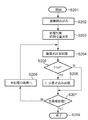
図2は、実施例1における地紋画像生成部101の内部処理手順を示すフローチャートである。初めにユーザインターフェース等を通じてステップS201で、地紋画像生成処理が開始される。次に、ステップS202で、入力背景画像111、背景閾値パターン116、潜像閾値パターン114、潜像背景領域指定画像115、カモフラージュ領域指定画像117を読み込む。
FIG. 2 is a flowchart illustrating an internal processing procedure of the tint block
次に、ステップS203で、地紋画像を生成する際の初期画素を決定する。例えば、入力画像全体に対して左上から右下までラスター走査順に画像処理を行い、地紋画像に変更する場合、左上を初期位置とする。 Next, in step S203, an initial pixel for generating a tint block image is determined. For example, when the entire input image is subjected to image processing in the order of raster scanning from the upper left to the lower right, and changed to a tint block image, the upper left is set as the initial position.
次に、ステップS204では、背景閾値パターン116、潜像閾値パターン114、潜像背景領域指定画像115、カモフラージュ画像117は入力背景画像111の左上からタイル上に配置するとし、処理対象となっている入力背景画像111の画素に対して、以下の式(1)を計算し、印刷時のドットに対応する画素値を書き込むか否かを判定する。このとき画素値は入力された色情報112に対応する。
Next, in step S204, the

ここで、式(1)の構成要素の定義を以下に示す。
nCamouflage:カモフラージュ領域指定画像で画素がカモフラージュ領域であれば0、そうでなければ1
nSmallDotOn:背景閾値パターンの画素値が黒であれば1、白であれば0
nLargeDotOn:潜像閾値パターンの画素値が黒であれば1、白であれば0
nHiddenMark:潜像背景領域指定画像で潜像部に相当する画素であれば1、背景部に相当する画素であれば0
/nHiddenMark:nHiddenMarkの否定。潜像部で0、背景部で1となる。
Here, the definition of the component of Formula (1) is shown below.
nCamouflage: 0 if the pixel is a camouflage area in the camouflage area designation image, 1 otherwise
nSmallDotOn: 1 if the pixel value of the background threshold pattern is black, 0 if white
nLargeDotOn: 1 if the pixel value of the latent image threshold pattern is black, 0 if white
nHiddenMark: 1 if a pixel corresponding to a latent image portion in a latent image background area designation image, 0 if a pixel corresponding to a background portion
/ nHiddenMark: Denial of nHiddenMark. 0 in the latent image portion and 1 in the background portion.
尚、このとき入力背景画像の画素値を参照しながら、印刷時のドットに対応する画素値を書き込むか否かを判定しても良い。この場合、式(1)の右辺に入力背景画像を参照して得られる項目(nBackground)を乗算すると良い。このnBackgroundは、入力背景画像が特定の画素値を持つ領域(白地領域)ならば1、そうでないなら0とする。 At this time, it may be determined whether or not to write a pixel value corresponding to a dot at the time of printing while referring to the pixel value of the input background image. In this case, it is preferable to multiply an item (nBackground) obtained by referring to the input background image on the right side of Expression (1). This nBackground is 1 if the input background image has a specific pixel value (white background area), and 0 otherwise.
また、各処理対象画素で、式(1)の全ての要素を用いて計算する必要はない。以下のように、不必要な計算を省くことで処理の高速化を図れる。 Moreover, it is not necessary to calculate using all the elements of Formula (1) for each pixel to be processed. As described below, the processing speed can be increased by eliminating unnecessary calculations.
例えば、nHiddenMark=1ならば、/nHiddenMark=0、nHiddenMark=0ならば/nHiddenMark=1となる。従って、nHiddenMark=1ならば、式(2)の値をnLargeDotOnの値とし、nHiddenMark=0ならば、式(2)の値をnSmallDotOnの値とすると良い。 For example, if nHiddenMark = 1, / nHiddenMark = 0, and if nHiddenMark = 0, / nHiddenMark = 1. Therefore, if nHiddenMark = 1, the value of equation (2) is the value of nLargeDotOn, and if nHiddenMark = 0, the value of equation (2) is preferably the value of nSmallDotOn.
また、nCamouflageの値は全体にかかる積算であり、nCamouflage=0であれば、nWriteDotOn=0となる。従って、nCamouflage=0の場合はnCamouflage以降の式(2)の計算を省略すると良い。 Further, the value of nCamouflage is an integration over the whole. If nCamouflage = 0, nWriteDotOn = 0. Therefore, in the case of nCamouflage = 0, the calculation of equation (2) after nCamouflage may be omitted.
![]()
![]()
また、生成される地紋画像では、背景閾値パターン116、潜像閾値パターン114、潜像背景領域指定画像115、カモフラージュ領域指定画像117の縦横の長さの最小公倍数の大きさの画像が繰り返しの最小単位となるため、地紋画像生成部101では、繰り返しの最小単位である地紋画像の一部分のみを生成し、その地紋画像の一部分を入力背景画像の大きさにタイル状に繰り返し並べると、地紋画像118の生成にかかる処理時間を短縮できる。
次に、ステップS205では、ステップS204での計算結果(nWriteDotOnの値)を判定する。ここで、nWriteDotOn=1ならばステップS206へ進み、nWriteDotOn=0ならばステップS207へ進む。
Further, in the generated tint block image, an image having a size of the least common multiple of the vertical and horizontal lengths of the
Next, in step S205, the calculation result (value of nWriteDotOn) in step S204 is determined. If nWriteDotOn = 1, the process proceeds to step S206. If nWriteDotOn = 0, the process proceeds to step S207.
このステップS206では、印刷時のドットに対応する画素値を書き込む処理を行う。画素値の値は、地紋画像118の色により変えることができる。黒色の地紋を作成したい場合、入力背景画像111の処理対象画素を黒に設定する。その他、プリンタのトナー又はインクの色に合わせてシアン、マゼンダ、イエローに設定すれば、カラーの地紋画像118を作成することもできる。
In step S206, a process of writing pixel values corresponding to dots at the time of printing is performed. The value of the pixel value can be changed depending on the color of the
入力背景画像111が1画素当たり1〜数ビットの画像データである場合には、インデックスカラーを用いて画素値を表現すれば良い。インデックスカラーとは、画像データの表現方法で、対象とするカラー画像で頻繁に出現する色情報を目次に設定し(例えばインデックス0は白、インデックス1はシアンなど)、各画素の値は色情報を記載した目次の番号で表現する(例えば、1番目の画素値はインデックス1の値、2番目の画素値はインデックス2の値、…と表現する。)
ステップS207では、入力背景画像111の処理対象領域の全画素が処理されたかを判定する。入力背景画像111の処理対象領域の全画素が処理されていない場合はステップS208へ進み、未処理の画素を選択し、再びステップS204〜ステップS206の処理を実行する。また、入力背景画像111の処理対象領域の全画素に対する処理が完了していれば、ステップS209へ進み、地紋画像生成部101における画像処理を終了する。上述の処理により、入力背景画像111に対して画像処理を加えた地紋画像118が生成できる。
When the
In step S207, it is determined whether all pixels in the processing target area of the
次に、実施例での潜像部と背景部におけるドットの配置方法について説明する。実施例では、潜像部をドット集中型ディザマトリクス、背景部をドット分散型ディザマトリクスに基づいて生成する場合について説明する。また潜像部を生成する際に用いるドット集中型ディザマトリクスの代表としては、渦巻き型ディザマトリクスが挙げられる。 Next, a method for arranging dots in the latent image portion and the background portion in the embodiment will be described. In the embodiment, a case where a latent image portion is generated based on a dot concentration type dither matrix and a background portion is generated based on a dot dispersion type dither matrix will be described. A representative example of the dot concentration type dither matrix used when generating the latent image portion is a spiral dither matrix.
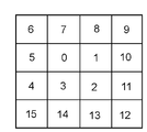
図3は、4×4の渦巻き型ディザマトリクスの一例を示す図である。4×4の渦巻き型ディザマトリクスの閾値は渦巻状に中心から数値が増加する形で配置されている。 FIG. 3 is a diagram illustrating an example of a 4 × 4 spiral dither matrix. The threshold values of the 4 × 4 spiral dither matrix are arranged in a spiral shape with numerical values increasing from the center.
図4は、図3の4×4の渦巻き型ディザマトリクスを用いて所定の入力画像信号を閾値処理して得られる閾値パターン(ドット配置)を表す図である。図4において、401、402、403は入力画像信号3、6、9を図3のディザマトリクスでそれぞれ閾値処理して得られる閾値パターンを示している。ここで得られる閾値パターン(ドット配置)は、各々のドットが集中して配置されるパターンとなっている。 FIG. 4 is a diagram showing a threshold pattern (dot arrangement) obtained by performing threshold processing on a predetermined input image signal using the 4 × 4 spiral dither matrix of FIG. 4, 401, 402, and 403 indicate threshold patterns obtained by performing threshold processing on the input image signals 3, 6, and 9, respectively, using the dither matrix of FIG. The threshold pattern (dot arrangement) obtained here is a pattern in which each dot is arranged in a concentrated manner.
一方、背景部を構成するドット分散型ディザマトリクスの代表としては、Bayer型ディザマトリクスが挙げられる。Bayer型のN×Nディザマトリクスは次式で表される。 On the other hand, a Bayer type dither matrix is a representative example of the dot dispersion type dither matrix that constitutes the background portion. The Bayer type N × N dither matrix is expressed by the following equation.
但し、Nは2のべき乗、UNは各要素が1のN×Nマトリックスである。
図5は、4×4のBayer型ディザマトリクスの一例を示す図である。任意の入力画像信号をBayer型ディザマトリクスでディザ処理を行って生成される閾値パターンは、各々のドットが分散して配置されるように設計されている。
However, N is the power of 2, U N is the N × N matrix of each
FIG. 5 is a diagram illustrating an example of a 4 × 4 Bayer-type dither matrix. A threshold pattern generated by dithering an arbitrary input image signal with a Bayer-type dither matrix is designed so that each dot is arranged in a distributed manner.
図6は、図5の4×4のBayer型ディザマトリクスを用いて所定の入力画像信号を閾値処理して得られる閾値パターン(ドット配置)を表す図である。図6において、601、602、603は入力画像信号2、4、5を図5のディザマトリクスでそれぞれ閾値処理して得られる閾値パターンを示している。ここで得られる閾値パターン(ドット配置)は、各々のドットがお互いに分散して配置されるパターンとなっている。Bayer型ディザマトリクスでは、閾値マトリクスの各要素は相互になるべく接触しない位置に順に配置され、その閾値パターンは孤立した格子状のドット配置を取る。Bayer型ディザでは、ディザマトリクスのサイズが大きくなるとマトリクスによる周期的なテクスチャが目立つ場合も存在するが、特定の階調では、周期的で美しいパターンが得られるメリットがある。
FIG. 6 is a diagram illustrating a threshold pattern (dot arrangement) obtained by performing threshold processing on a predetermined input image signal using the 4 × 4 Bayer-type dither matrix of FIG. 6,
本実施例では、背景に用いるディザマトリクスとして以降、Bayer型ディザマトリクスを用いる場合を中心に説明するが、Bayer型ディザマトリクスに限定するものではない。その他のドット分散型ディザマトリクスを用いても良い。 In the present embodiment, the case where a Bayer type dither matrix is used as a background dither matrix will be mainly described below, but the dither matrix is not limited to the Bayer type dither matrix. Other dot dispersion type dither matrices may be used.
例えば、ブルーノイズマスクも、背景に用いるドット分散型ディザマトリクスの一例である。このブルーノイズマスクは、任意の階調での閾値パターンが全てブルーノイズ特性を有し、閾値パターンを形成する黒画素の分布がランダムではあるが一様性が高く、粒状性が目立ちにくい。また、ブルーノイズ特性とは、任意の階調に設定した場合の点の出力パターンが局所的に非周期的(locally aperiodic)、かつ等方的(isotropic)で低周波成分が少ないことを意味する。ブルーノイズマスクから得られる閾値パターンはモアレの発生を防止し、紙送りムラを目立ちにくくするなど、視覚的に好ましい出力パターンが得られる長所がある。 For example, a blue noise mask is an example of a dot dispersion type dither matrix used for the background. In this blue noise mask, all threshold patterns in an arbitrary gradation have blue noise characteristics, and the distribution of black pixels forming the threshold pattern is random but highly uniform, and the graininess is not conspicuous. The blue noise characteristic means that the output pattern of points when set to an arbitrary gradation is locally aperiodic and isotropic and has low frequency components. . The threshold pattern obtained from the blue noise mask has advantages in that a visually preferable output pattern can be obtained, for example, by preventing the occurrence of moire and making paper feed unevenness inconspicuous.
また、ブルーノイズマスクでなくとも、特定又は任意の階調での閾値パターンが周期的(又は擬似周期的)、かつ非等方的で低周波成分が少ないドット分散型ディザマトリクスを用いても良い。また閾値パターンを用いる方法ではないが、本実施例では誤差拡散法を用いた背景部の構成も可能である。既に述べたベイヤー型ディザマトリクスやブルーノイズマスクを用いて背景閾値パターンを生成した場合、式(1)における nSmallDotOnの値は背景閾値パターンを参照することで読み出すことが出来る。一方、誤差拡散法を用いる場合は、1画素ごとに背景の濃さに対応する階調と周囲の画素から伝播された誤差分の和を所定の閾値と比較し、処理対象画素におけるドットのOn/Offを決定し、nSmallDotOnの値として用いると良い。このとき、ドットのOn/Offで生じた誤差は重みをつけて近傍画素に分配される。未処理の画素の画素値は背景の濃さに対応する元の入力画素値と分配された誤差の和となっている。なお、背景閾値パターンと同様、背景の濃さに対応する階調は予め準備されているとする。誤差拡散法は処理時間がかかるデメリットがあるが、ドットが均一に分散した視覚特性の良い画像が得られるメリットがある。誤差拡散法については既によく知られているため、本実施例では詳しい説明は省略する。同様に、誤差拡散法を改良した方法も適用可能である。 Further, a dot dispersion type dither matrix may be used that is not a blue noise mask but has a periodic (or pseudo-periodic) threshold pattern at a specific or arbitrary gradation, is anisotropic, and has low low frequency components. . Further, although not a method using a threshold pattern, in the present embodiment, a configuration of a background portion using an error diffusion method is also possible. When the background threshold pattern is generated using the Bayer-type dither matrix or the blue noise mask already described, the value of nSmallDotOn in Equation (1) can be read by referring to the background threshold pattern. On the other hand, when the error diffusion method is used, the tone corresponding to the background density for each pixel and the sum of the error propagated from the surrounding pixels are compared with a predetermined threshold value, and the dot On in the pixel to be processed is turned on. / Off is determined and used as the value of nSmallDotOn. At this time, an error caused by dot On / Off is weighted and distributed to neighboring pixels. The pixel value of the unprocessed pixel is the sum of the original input pixel value corresponding to the background density and the distributed error. As in the case of the background threshold pattern, it is assumed that the gradation corresponding to the background density is prepared in advance. The error diffusion method has a demerit that takes a long time, but has an advantage that an image with good visual characteristics in which dots are uniformly dispersed can be obtained. Since the error diffusion method is already well known, detailed description thereof is omitted in this embodiment. Similarly, a method obtained by improving the error diffusion method is also applicable.
また、各階調における閾値パターンは、ディザマトリクスに基づき生成しなくてもよい。階調毎に独自に背景閾値パターン、潜像閾値パターンを生成してもよい。この場合、各階調毎に画質のよい閾値パターンを集めることが出来るメリットもある。 Further, the threshold pattern for each gradation may not be generated based on the dither matrix. A background threshold pattern and a latent image threshold pattern may be independently generated for each gradation. In this case, there is also an advantage that threshold patterns with good image quality can be collected for each gradation.
図7は、背景閾値パターンと潜像閾値パターンの黒画素の面積比率を比較するための図である。図7に示すように、背景ディザマトリクスの縦と横の大きさをX_S、Y_Sとし、入力画像信号の階調をT_Sとし、潜像ディザマトリクスの縦と横の大きさをX_L、Y_Lとし、入力画像信号の階調をT_Lとする。 FIG. 7 is a diagram for comparing the area ratio of black pixels in the background threshold pattern and the latent image threshold pattern. As shown in FIG. 7, the vertical and horizontal sizes of the background dither matrix are X_S and Y_S, the gradation of the input image signal is T_S, and the vertical and horizontal sizes of the latent image dither matrix are X_L and Y_L. Let T_L be the gradation of the input image signal.
そのとき、背景閾値パターン内の黒画素が占める割合はP_S=T_S/(X_S*Y_S)となり、潜像閾値パターン内の黒画素が占める割合はP_L=T_L/(X_L*Y_L)となる。 At that time, the ratio of black pixels in the background threshold pattern is P_S = T_S / (X_S * Y_S), and the ratio of black pixels in the latent image threshold pattern is P_L = T_L / (X_L * Y_L).
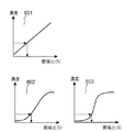
図8は、入力画像信号をディザマトリクスで閾値処理して得られる閾値パターンの黒画素の面積比率と、閾値パターンを印刷した時の濃度との関係を表す図である。尚、ディザ処理では、入力画像信号の階調に従って黒画素の面積比率が変化するため、図8の横軸を入力画像信号の階調と見ても良い。 FIG. 8 is a diagram illustrating the relationship between the area ratio of black pixels of a threshold pattern obtained by performing threshold processing on an input image signal with a dither matrix and the density when the threshold pattern is printed. In the dither processing, the area ratio of the black pixels changes according to the gradation of the input image signal, so the horizontal axis in FIG. 8 may be regarded as the gradation of the input image signal.
ここで、背景部のディザマトリクス(背景閾値パターン)と潜像部のディザマトリクス(潜像閾値パターン)とが同一の辺の大きさを持つ必要はなく、異なる大きさであっても良い。例えば、背景ディザマトリクスと潜像ディザマトリクスの階調特性が801に示すような同一の階調特性の場合、背景部のディザマトリクスと潜像部のディザマトリクスの大きさに関わらず、横軸の値(黒画素の面積比率)がほぼ等しいならば、即ち、P_SとP_Lがほぼ等しくなるような入力画像信号の階調T_S、T_Lの値を用いるならば、背景閾値パターンと潜像閾値パターンの濃度はほぼ等しくなり、潜像が目立たない地紋画像を生成することができる。 Here, the dither matrix (background threshold pattern) of the background portion and the dither matrix (latent image threshold pattern) of the latent image portion do not have to have the same side size, and may be different sizes. For example, when the gradation characteristics of the background dither matrix and the latent image dither matrix are the same as those shown in 801, the horizontal axis represents the dither matrix of the background portion and the latent image portion regardless of the size of the dither matrix. If the values (area ratio of black pixels) are substantially equal, that is, if the values of the gradations T_S and T_L of the input image signal such that P_S and P_L are substantially equal, then the background threshold pattern and the latent image threshold pattern It is possible to generate a copy-forgery-inhibited pattern image in which the densities are substantially equal and the latent image is not noticeable.
しかしながら、実際には、プリンタの特性により、背景ディザマトリクスと潜像ディザマトリクスの階調特性が必ずしも同一になるとは限らない。 However, actually, the gradation characteristics of the background dither matrix and the latent image dither matrix are not always the same due to the characteristics of the printer.
例えば、潜像ディザマトリクスの階調特性は802に示すような緩やかなS字カーブで、背景ディザマトリクスの階調特性は803に示すような急峻なS字カーブで表されるとする。このような場合、背景閾値パターンと潜像閾値パターンの黒画素の面積比率をほぼ等しく設定しても、印刷時の背景部と潜像部の濃度は同一にはならない。 For example, it is assumed that the gradation characteristic of the latent image dither matrix is represented by a gentle S-shaped curve as indicated by 802, and the gradation characteristic of the background dither matrix is represented by a steep S-shaped curve as indicated by 803. In such a case, the density of the background portion and the latent image portion at the time of printing is not the same even if the area ratio of the black pixels of the background threshold pattern and the latent image threshold pattern is set to be approximately equal.
背景部又は潜像部の一方、又は双方のディザマトリクスに対する入力画像信号を適当に調節することで、できるだけ他方の印刷時の濃度に近づけることができる。 By appropriately adjusting the input image signal for the dither matrix of one or both of the background portion and the latent image portion, the density at the time of the other printing can be made as close as possible.
また、背景ディザマトリクス又は潜像ディザマトリクスで表現可能な階調の数が大きければ、入力画像信号の階調の調整により、背景部又は潜像部の濃度を細かく調整することができる。 If the number of gradations that can be expressed by the background dither matrix or the latent image dither matrix is large, the density of the background portion or latent image portion can be finely adjusted by adjusting the gradation of the input image signal.
潜像ディザマトリクスが、図3に示すようなドット集中型ディザマトリクスの場合、入力画像信号の階調が一定以下となると孤立ドットに近くなり、複写時に潜像部が消失し易くなる。一方、入力画像信号の階調が一定以上となるとドットが集中して、潜像を構成する固まりのドット自体が人の目にはっきりと認識され易くなる。 When the latent image dither matrix is a dot-concentrated dither matrix as shown in FIG. 3, when the gradation of the input image signal is below a certain level, it becomes close to an isolated dot, and the latent image portion tends to disappear during copying. On the other hand, when the gradation of the input image signal exceeds a certain level, the dots are concentrated and the clustered dots constituting the latent image are easily recognized clearly by human eyes.
従って、潜像ディザマトリクスにおいては、取り得る入力画像信号の階調は一定の範囲に留めておいたほうが良い。また図3に示すような潜像ディザマトリクスにおいては、ディザマトリクスのサイズが変化しても入力画像信号の階調が同一であれば、ほぼ同一の集中したドット配置が得られる。従って、潜像ディザマトリクスに対する入力画像信号の階調を一定に保ち、ディザマトリクスのサイズを変化させることで、単位面積あたりの濃度を変えることも可能である。 Therefore, in the latent image dither matrix, it is better to keep the gradation of the possible input image signal within a certain range. In the latent image dither matrix as shown in FIG. 3, even if the size of the dither matrix changes, if the gradation of the input image signal is the same, substantially the same concentrated dot arrangement can be obtained. Therefore, it is possible to change the density per unit area by keeping the gradation of the input image signal with respect to the latent image dither matrix constant and changing the size of the dither matrix.
一方、背景ディザマトリクスが図8に示すようなドット分散型ディザマトリクスの場合、入力画像信号の階調を変化させることで全体的に均一にドットを打ちながら濃度を変化させることができる。従って、背景ディザマトリクスの階調が広い(即ち、ディザマトリクスの大きさが大きい)方が背景部の濃度調整に優れていると言える。 On the other hand, when the background dither matrix is a dot-dispersed dither matrix as shown in FIG. 8, the density can be changed while hitting dots uniformly throughout by changing the gradation of the input image signal. Therefore, it can be said that the background dither matrix having a wider gradation (that is, the dither matrix having a larger size) is superior in adjusting the density of the background portion.
尚、プリンタで偽造抑止地紋を出力する場合、プリンタの濃度変動に対して調整を行うための調整機能が必要となってくるが、これについては、後に詳しく述べる。 Note that when outputting a forgery-inhibited tint block with a printer, an adjustment function for adjusting the density variation of the printer is required, which will be described in detail later.
図9は、図1の地紋合成印刷装置を用いて地紋画像を生成する様子を示す模式図である。図9において、901、902、903はそれぞれ、潜像閾値パターン、背景閾値パターン、潜像背景領域指定画像を示し、904は式(1)に基づいて生成した地紋画像を示す。尚、904の生成段階ではカモフラージュ模様は導入されていない。
FIG. 9 is a schematic diagram showing how a tint block image is generated by using the tint block composition printing apparatus of FIG. In FIG. 9,
図9に示す地紋画像904では、丸で囲んだ領域910に示すように、潜像背景領域指定画像903の潜像と背景の切り替わり部分で潜像閾値パターンと背景閾値パターンが合体したドットの固まりが生成されている。このドットの固まりは、潜像背景領域指定画像903の潜像と背景の切り替わりと潜像閾値パターンの大きさが同期していないときに生じ易い。また、このドットの固まりは、潜像背景領域指定画像の潜像と背景の切り替わる部分にのみ集中して現われるため、潜像の概形が目立ち、偽造抑止地紋の効果が薄れるデメリットを生ずる。
In the copy-forgery-inhibited
従って、高画質の地紋画像を生成するためには、潜像背景領域指定画像の潜像と背景の切り替わりでドットの固まりが生じないようにする処理がある。 Therefore, in order to generate a high-quality copy-forgery-inhibited pattern image, there is a process of preventing dot clumps from occurring when the latent image and background image of the latent image background area designation image are switched.
実施例では、以降、潜像背景領域指定画像の潜像と背景の切り替わりでドットの固まりが生じないようにする処理を「バウンダリ処理」と呼ぶことにする。このバウンダリ処理の一例としては、繰り返し配置された潜像閾値パターンの中心(潜像閾値パターンの一辺の半分を切り捨てした画素分だけ左上から移動した画素を中心とする)に対応する、繰り返し配置された潜像背景領域指定画像の画素値のみを読み取ってHiddenMarkLatticeの値とし、同一の潜像閾値パターン内部に属する画素では同一のHiddenMarkLatticeの値を用いて処理する方法がある。この処理方法を数式で表現すると以下となる。 In the embodiment, hereinafter, a process for preventing dot clumps from occurring when a latent image and a background of a latent image / background area designation image are switched is referred to as a “boundary process”. As an example of this boundary processing, the repetitive arrangement corresponding to the center of the repetitively arranged latent image threshold pattern (centering on the pixel moved from the upper left by the amount of pixels obtained by discarding half of one side of the latent image threshold pattern) is performed. There is a method in which only the pixel value of the latent image background area designation image is read to obtain the HiddenMarkLattice value, and the pixels belonging to the same latent image threshold pattern are processed using the same HiddenMarkLattice value. This processing method is expressed as follows:
この方法を用いると、画像の端で無い限りは、潜像閾値パターンは周囲に潜像閾値パターンの白地を伴って構成される。従って、潜像閾値パターンの黒画素の周囲に白地が存在する場合、白地が緩衝地帯となって潜像閾値パターンの黒画素と背景閾値パターンの黒画素が接することが無くなり、潜像背景領域指定画像で指定する潜像と背景の切り替わる部分が目立つことが無くなる。
図9に示す905はバウンダリ処理を行った地紋画像である。905では潜像背景領域指定画像で指定する潜像と背景の切り替わり部分で潜像閾値パターンと背景閾値パターンが合体したドットの固まりが生じていないことが分る。
When this method is used, the latent image threshold pattern is configured with the white background of the latent image threshold pattern around it unless it is at the edge of the image. Therefore, if a white background exists around the black pixels of the latent image threshold pattern, the white background becomes a buffer zone and the black pixels of the latent image threshold pattern do not contact the black pixels of the background threshold pattern, and the latent image background area designation The part where the latent image specified in the image and the background are switched does not stand out.
905 shown in FIG. 9 is a tint block image that has undergone boundary processing. In 905, it can be seen that there is no cluster of dots in which the latent image threshold pattern and the background threshold pattern are merged at the switching portion between the latent image specified in the latent image background area designation image and the background.
また、別のバウンダリ処理の一例としては、入力される潜像背景領域指定画像における潜像と背景の切り替わりを潜像閾値パターンの大きさに同期するように前処理する方法がある。この方法では、まず、潜像背景領域指定画像内に潜像閾値パターンを繰り返し配置し、潜像閾値パターンの中心に対応する潜像背景領域指定画像の画素値を読み取り、サブサンプリングした潜像背景領域指定画像を生成する。次に、サブサンプリングした潜像背景領域指定画像を新たに1画素が潜像閾値パターンの大きさの整数倍となるように拡大し、修正した潜像背景領域指定画像を作成する。最後に、修正した潜像背景領域指定画像に対し、式(1)に基づいて地紋画像を生成すれば、910に示すようなドットの固まりを生じずに、地紋画像を生成することができる。 As another example of the boundary processing, there is a method of pre-processing so that the switching between the latent image and the background in the input latent image background area designation image is synchronized with the size of the latent image threshold pattern. In this method, first, a latent image threshold area pattern is repeatedly arranged in the latent image background area designation image, the pixel value of the latent image background area designation image corresponding to the center of the latent image threshold pattern is read, and the subsampled latent image background is obtained. An area designation image is generated. Next, the subsampled latent image background area designation image is newly enlarged so that one pixel becomes an integral multiple of the size of the latent image threshold pattern, and a corrected latent image background area designation image is created. Finally, if a copy-forgery-inhibited pattern image is generated based on the formula (1) for the corrected latent image background area designation image, the copy-forgery-inhibited pattern image can be generated without causing a cluster of dots as shown in 910.
地紋生成部101に上述の「バウンダリ処理」を追加すると、潜像背景領域指定画像で指定する潜像と背景の切り替わり部分を潜像閾値パターンの大きさと同期させて潜像背景領域指定画像を作成する必要が無いため、利用者にとっても使い勝手が良い。
When the above-described “boundary processing” is added to the tint
図12は、バウンダリ処理により地紋生成部101で生成された地紋画像の一部を示す図である。図12で示す地紋画像を生成する際には、潜像背景領域指定画像、カモフラージュ領域指定画像は、それぞれ図10に示す1001、1002の画像を用い、潜像閾値パターン、背景閾値パターンは、それぞれ図11に示す1101、1102の画像を用いている。尚、1001、1002、1101、1102の画像を囲む破線は画像の境界を示しており、実際の画像には存在しない。図12の地紋画像はバウンダリ処理が施されているため、潜像部と背景部の境界でドット固まる現象が起きておらず、潜像部が判別しにくくなっている。
FIG. 12 is a diagram showing a part of the tint block image generated by the tint
次に、上述した地紋生成部101で生成された地紋画像と入力原稿画像(例えば、帳票や証明書)を合成する合成部102における処理について説明する。
Next, a description will be given of processing in the combining
図13は、入力原稿画像と地紋画像の合成処理を示す模式図である。図13において、1301はテキスト属性のデータ、1302はグラフィック属性のデータ、1303はイメージ属性の地紋画像を表している。
FIG. 13 is a schematic diagram showing a composition process of an input document image and a tint block image. In FIG. 13,
合成部102では、OSの描画インターフェースを用いて,1301〜1303の夫々の画像を配置に関する優先順位(レイヤー構造)に従ってソフトウェア的に重ね合わせ、1304に示すようなテキスト属性のデータ、グラフィック属性のデータ、イメージ属性の地紋画像が合成された画像を生成する。この処理はコンピュータの一般的なアプリケーションであるドローイングソフトにおける画面描画(ディスプレイ描画)とほぼ同様の処理である。尚、合成部102ではOSの描画インターフェース処理に頼ることなく、独自に画像の合成処理を行っても良い。
The
図13に示す例では、イメージ属性の地紋画像1303は、テキスト属性のデータ1301、グラフィック属性のデータ1302と比べて最下位のレイヤーとして重ね合わせられている。例えば、イメージ属性の地紋画像1303とテキスト属性のデータ1301が重なる位置では、テキスト属性のデータ1301を優先して描画する。従って、地紋画像は入力原稿画像の背景に適切に配置され、テキスト属性のデータやグラフィック属性のデータの視認性を低下させることは無い。
In the example shown in FIG. 13, the copy-forgery-inhibited
また、図13に示す例では、地紋画像1303は入力画像と同じ大きさの画像となっているが、一部の領域にのみ地紋画像を重ね合わせたい場合には、地紋画像生成部101で一部の領域に相当する大きさの入力背景画像を入力し、入力した画像サイズに一致する地紋画像だけを生成し、合成部102で入力原稿画像と合成すれば良い。生成する地紋画像が小さい分だけ、地紋画像生成部101での処理を高速化できる。
In the example shown in FIG. 13, the copy-forgery-inhibited
また、合成部102で出力する地紋合成出力原稿画像はOSの描画インターフェースで表現されたデータであっても良いし、合成された結果のビットマップ画像であっても良い。そして、この合成部102で生成された地紋合成出力原稿画像は後段の印刷データ処理部103に送られる。
The copy-forgery-inhibited pattern output document image output by the combining
印刷データ処理部103では、OSの描画インターフェースを介して、合成部102で合成された地紋合成出力原稿画像を描画情報として受け取り、逐次印刷コマンドへと変換していく。このとき、必要に応じてカラーマッチング処理やRGB−CMYK変換、ハーフトーン処理などの画像処理を実行する。そして、印刷データ処理部103は、地紋合成出力原稿画像データとして、印刷部104で解釈可能なデータ形式(例えば、ページ記述言語で記述されたデータ形式や印刷ビットマップに展開されたデータ形式)を後段の印刷部104に送る。
The print
印刷部104では、入力された地紋合成出力原稿画像データの情報に従って、地紋合成出力原稿を印刷出力する。
The
図14は、様々な画像が既に合成されたレイヤー構造をもたない入力原稿画像に対して地紋画像を合成する方法を示す模式図である。図14において、1401は様々な画像が既に合成されたレイヤー構造をもたない入力原稿画像であり、1402は特定の画素値を持つ領域(例えば白地領域)で地紋画像を配置したい領域を示している。
FIG. 14 is a schematic diagram showing a method for synthesizing a tint block image with an input document image having no layer structure in which various images have already been synthesized. In FIG. 14,
尚、入力原稿画像1401のその他の領域は特定の画素値を持たない(例えば白地領域でない)とする。
It is assumed that the other area of the
図15は、様々な画像が既に合成されたレイヤー構造をもたない入力原稿画像に対して地紋画像を合成するための地紋合成印刷装置の内部構成を示すブロック図である。図15に示す地紋合成印刷装置は、様々な画像が既に合成されたレイヤー構造をもたない画像(例えば1401)に対して地紋画像を合成する場合に適している。 FIG. 15 is a block diagram showing an internal configuration of a tint block synthesizing printing apparatus for synthesizing a tint block image with an input document image having no layer structure in which various images have already been synthesized. The copy-forgery-inhibited pattern combination printing apparatus shown in FIG. 15 is suitable for combining a copy-forgery-inhibited pattern image with an image (for example, 1401) in which various images have already been combined and have no layer structure.
図15に示すように、この地紋合成印刷装置は、地紋画像合成出力原稿生成部1501と印刷データ処理部1502、印刷部1503から構成されている。まず、地紋画像合成出力原稿生成部1501には、入力原稿画像、色情報、処理領域情報、潜像閾値パターン、背景閾値パターン、潜像背景領域指定画像、カモフラージュ領域指定画像、が入力され、地紋画像合成入力原稿を生成出力する。
As shown in FIG. 15, this tint block composition printing apparatus includes a tint block image composition output
また、地紋画像合成出力原稿生成部1501では、入力原稿画像の特定の画素値を持つ領域(例えば白地領域)を検出し、その領域にのみ地紋画像を合成し、地紋画像合成入力原稿画像を出力する。具体的には、式(3)に対して入力原稿画像を参照する項目(nBackground)を積算した以下の式を用いて、入力原稿画像中の画素に地紋画像に相当する画素値を書き込むか否かを判定する。
The copy-forgery-inhibited pattern image output
ここでnBackgroundは入力原稿画像が特定の画素値を持つ領域(白地領域)ならば1、そうでないなら0とする。
図1に示した地紋画像生成部101と同様に、地紋画像合成出力原稿生成部1501においても不要な計算を省くことで高速化を実現できる。nBackgroundは全体に対する積算であるため、nBackground=1となる画素に対してのみ、式(3)を計算し、地紋画像に相当する画素値を書き込むか否かを判定する。
Here, nBackground is set to 1 if the input original image has a specific pixel value (white background area), and is set to 0 otherwise.
Similar to the copy-forgery-inhibited pattern
入力原稿画像の画素値を参照する以外は、図1に示した地紋生成部101とほぼ同様の処理を行うため、詳しい説明は省略する。
Except for referring to the pixel value of the input original image, the process is substantially the same as that of the tint
地紋画像合成出力原稿生成部1501で生成した地紋合成出力原稿画像は、印刷データ処理部1502に出力される。印刷データ処理部1502では、図1の印刷データ処理部103とほぼ同じ処理を行う。このとき、地紋画像が合成された領域は1画素の画素値が印刷時に異なる複数のインクやトナーで表現されて混色のドットと成らないように、カラーマッチング等の色変換処理をパスした画像処理を行うと良い。
The tint block composition output document image generated by the tint block image composition output
印刷データ処理部1502は更に、印刷部1504で解釈可能なデータ形式(例えば、ページ記述言語で記述されたデータ形式や印刷ビットマップに展開されたデータ形式)に変換し、地紋合成出力原稿画像データとして後段の印刷部1503に送る。
The print
次に、印刷部1503では、入力された地紋合成出力原稿画像データの情報に従って、地紋合成出力原稿を印刷出力する。これにより、入力原稿画像の特定の画素値を持つ領域(例えば白地領域)に地紋画像を合成し、出力することができる。
Next, the
上述の実施例によれば、既に2値化されたパターンである背景閾値パターンと潜像閾値パターン、潜像部と背景部を指定する2値画像である潜像背景領域指定画像、カモフラージュ領域を指定する2値画像であるカモフラージュ領域画像、入力画像の画素値が所定の画素であるか否かを表すビット情報を用いて論理演算を実行することにより、入力画像の所定の領域に効率的に地紋画像を配置・合成することができる。 According to the above-described embodiment, the background threshold pattern and the latent image threshold pattern which are already binarized patterns, the latent image background area designating image which is a binary image designating the latent image part and the background part, and the camouflage area are obtained. By performing a logical operation using a camouflage area image, which is a binary image to be specified, and bit information indicating whether the pixel value of the input image is a predetermined pixel, it is efficiently applied to the predetermined area of the input image. A tint block image can be arranged and synthesized.
また、2値画像である背景閾値パターンと潜像閾値パターン、潜像部と背景部を指定する2値画像である潜像背景領域指定画像、カモフラージュ領域を指定する2値画像であるカモフラージュ領域画像を用いて論理演算に基づき地紋画像を生成することにより、高速、かつ省メモリで地紋画像を生成することができる。 In addition, a background threshold pattern and a latent image threshold pattern that are binary images, a latent image background area designation image that is a binary image that designates a latent image portion and a background portion, and a camouflage area image that is a binary image that designates a camouflage area By generating a copy-forgery-inhibited pattern image based on a logical operation using, a copy-forgery-inhibited pattern image can be generated at high speed and with a reduced memory.
また、必要に応じて入力画像の画素値を参照し、入力画像の画素値が所定の画素であるか否かを表すビット情報を用いた論理演算により、入力画像中に地紋画像を合成するか否かを判定すれば、入力画像の所定の領域(例えば白地領域)に効率的に地紋画像を配置することもできる。 Whether to copy the copy-forgery-inhibited pattern image into the input image by referring to the pixel value of the input image as necessary and performing a logical operation using bit information indicating whether the pixel value of the input image is a predetermined pixel or not. If it is determined whether or not, the tint block image can be efficiently arranged in a predetermined area (for example, a white area) of the input image.
ここまで地紋画像の生成方法と地紋画像を入力原稿画像の合成方法について詳しく説明してきたが、プリンタを用いて実際に地紋画像を出力する場合、様々な原因により、必ずしも潜像部と背景部が意図した通りの濃度で出力されるとは限らない。 Up to this point, the method for generating the copy-forgery-inhibited pattern image and the method for synthesizing the copy-forgery-inhibited pattern image with the input original image have been described in detail. However, when the copy-forgery-inhibited pattern image is actually output using a printer, the latent image portion and the background portion are not necessarily displayed due to various causes. It is not always output at the intended density.
理由としては、プリンタのエンジン特性や閾値パターンを出力するディザマトリクスの違い、プリンタの個体差、湿度や気温などの印刷環境、エンジンの耐久性、用紙(メディア)の違い、プリンタのインクやトナーの違い等の様々な条件に依存した濃度不安定性を挙げることができる。即ち、背景部と潜像部のディザマトリクスのそれぞれに対する最適な入力階調は、プリンタの機種、ディザマトリクス、プリンタの個体、印刷環境、用紙、インクやトナー等に依存して異なる可能性がある。 Reasons include printer engine characteristics and dither matrix output of threshold patterns, individual printer differences, printing environment such as humidity and temperature, engine durability, differences in paper (media), printer ink and toner Concentration instability depending on various conditions such as differences can be mentioned. That is, the optimum input gradation for each of the background portion and latent image portion dither matrix may differ depending on the printer model, dither matrix, individual printer, printing environment, paper, ink, toner, and the like. .
従って、プリンタのエンジン特性や印刷環境が異なる場合においても、印刷時にほぼ等しい濃度となる背景閾値パターン、潜像閾値パターンを得た上で地紋画像を生成する必要がある。しかしながら、印刷環境による変動を含む全ての変動要因を考慮し、最適な背景閾値パターン、潜像閾値パターンを自動的に計算することは現実的には難しい。 Therefore, even when the engine characteristics and the printing environment of the printer are different, it is necessary to generate a copy-forgery-inhibited pattern image after obtaining a background threshold pattern and a latent image threshold pattern having substantially the same density during printing. However, it is practically difficult to automatically calculate the optimum background threshold pattern and latent image threshold pattern in consideration of all the fluctuation factors including fluctuation due to the printing environment.
従って、地紋合成印刷装置を実行する前に、プリンタ毎に背景部と潜像部の濃度がほぼ同一になる背景閾値パターンと潜像閾値パターンを得る機能、即ち、地紋濃度キャリブレーション機能の実装が必要となる。 Therefore, before executing the tint block synthesizing printing apparatus, a function for obtaining a background threshold pattern and a latent image threshold pattern in which the density of the background portion and the latent image portion are almost the same for each printer, that is, a tint block density calibration function is implemented. Necessary.
この地紋濃度キャリブレーション機能を実装する方法としては、背景ディザマトリクス、潜像ディザマトリクスの一方又は双方に対する入力画像信号の階調を変化させて、濃度がほぼ等しくなるように調整する方法が考えられる。 As a method for implementing this tint block density calibration function, a method of adjusting the gradation of the input image signal to one or both of the background dither matrix and the latent image dither matrix and adjusting the density to be approximately equal is conceivable. .
図16は、潜像閾値パターン及び複数の入力画像信号の階調に対してディザマトリクスで閾値処理して得られる背景閾値パターンを示す図である。図16において、1601は一辺10画素の潜像ディザマトリクスに対して階調6を入力して得られる潜像閾値パターンであり、黒画素の面積比率は6%となっている。
FIG. 16 is a diagram illustrating a background threshold pattern obtained by performing threshold processing with a dither matrix on the latent image threshold pattern and the gradations of a plurality of input image signals. In FIG. 16,
一方、1602〜1604は一辺16画素の背景ディザマトリクスに対してそれぞれ階調12、16、20を入力して得られる背景閾値パターンであり、それぞれ黒画素の面積比率は4.69%、6.25%、7.81%となっている。仮に背景ディザマトリクスが4×4画素であり、4×4画素の背景ディザマトリクスに対して入力画像信号の階調を変化させて濃度調整を行ったとすると、黒画素の面積比率は4×4+1=17段階のレンジしか持たず、約6%ステップの階調変化しか与えられないため、微妙な濃度調整ができない。
On the other hand, 1602 to 1604 are background threshold patterns obtained by inputting
しかしながら、1602〜1604に示すように、表現可能な階調数が多いディザマトリクスから出力される背景閾値パターンは、入力画像信号の階調の選択によって細かく濃度が調節可能であり、濃度キャリブレーションに適していることが分かる。 However, as shown in 1602 to 1604, the background threshold pattern output from the dither matrix having a large number of expressible gradations can be finely adjusted in density by selecting the gradation of the input image signal. It turns out that it is suitable.
以下に、地紋濃度キャリブレーション機能を実現するための地紋濃度試し刷りの概要について説明する。地紋濃度試し刷りは、コンピュータ上のアプリケーション又はプリンタドライバにおいて実装することが可能である。 The outline of the background pattern density test printing for realizing the background pattern density calibration function will be described below. The copy-forgery-inhibited pattern density test printing can be implemented by an application on a computer or a printer driver.
図22は、地紋濃度試し刷りを実行する装置の内部構成を示すブロック図である。図22に示すように、地紋濃度試し刷りを実行する装置は、設定情報入力部2201、パターン生成部2202、試し刷り地紋画像生成部2203、印刷データ処理部2204、印刷部2205から構成されている。
FIG. 22 is a block diagram illustrating an internal configuration of an apparatus that executes a tint block density test print. As shown in FIG. 22, the apparatus for executing the tint block density trial printing is configured by a setting
尚、装置の構成はこれに限らず、本発明における課題を解決可能な構成を有していれば良い。また、地紋濃度試し刷り専用の装置である必要も無い。 Note that the configuration of the apparatus is not limited to this, and it is only necessary to have a configuration capable of solving the problems in the present invention. Further, it is not necessary to use a device dedicated to the background pattern density test printing.
まず、設定情報入力部2201では、設定情報が保存されている初期設定ファイルから設定情報を読み取る処理を行うか、ユーザインターフェースを通じて入力される設定情報の受け付ける処理を行う。次に、パターン生成部2202では、設定情報入力部2201から入力される設定情報に基づき、地紋を生成するために必要なパターンを生成し、後段の試し刷り地紋画像生成部に出力する。本実施例の場合、入力される設定情報から生成されるパターンは背景閾値パターンと潜像閾値パターンとなる。また、地紋濃度試し刷り処理においては、パターン生成部2202は複数の背景閾値パターンと潜像閾値パターンを生成する。
First, the setting
次に、試し刷り地紋画像生成部2203では、パターン生成部2202から入力されたパターンに基づき、試し刷り地紋画像を生成する。この試し刷り地紋画像生成部2203で生成される試し刷り地紋画像の詳細については後に詳しく述べる。
Next, a trial printed tint block
次に、印刷データ処理部2204では、試し刷り地紋画像生成部2203で生成された試し刷り地紋画像に対し、必要な画像処理を実行する。但し、印刷データ処理部では地紋画像の画素値(シアン、マゼンダ、イエロー、ブラック)に対しては、印刷時に複数のインクやトナーが混じった混色とならないように考慮して地紋合成出力原稿画像に画像処理を行う。必要な画像処理が施された試し刷り地紋画像はプリンタが解釈可能なデータ形式(例えば、ページ記述言語で記述されたデータ形式や印刷ビットマップに展開されたデータ形式)に変換され、後段の印刷部2204へ送られる。そして、印刷部2204では、入力されたデータに従って、試し刷り地紋画像を印刷出力する。
Next, the print
次に、試し刷り地紋画像生成部2203で生成される、背景部と潜像部の双方の濃度を変化させた複数の地紋画像(パッチ)を2次元的に配置した試し刷りシートについて説明する。背景部と潜像部の濃度を2次元的に変化させた試し刷りシートには、薄い濃度の地紋から濃い濃度の地紋も印刷されており、1枚のシート内に背景部と潜像部の濃度がほぼ同じになる複数のパッチが存在する。従って、地紋の濃度も選択可能な入力値としてユーザに提示することができる。
Next, a description will be given of a test print sheet in which a plurality of copy-forgery-inhibited pattern images (patches) generated by the test-printed copy-forgery-inhibited pattern
ここまでプリンタによるオンデマンド地紋出力法では、潜像背景領域指定画像、カモフラージュ領域指定画像、色情報はユーザが自由に選択できることを述べてきたが、地紋の濃度もユーザが選択可能な入力値とすることができ、地紋の濃度を選択する手段を提供できるなら、ユーザにとっても選択肢が増えるメリットがある。そこで、ユーザの使い勝手を高めるため、最適な地紋画像の濃度に素早く見つけることのできる工夫が必要となってくる。1枚のシート内に、背景部と潜像部の双方の濃度を変化させて2次元的に配置した試し刷りシートを用いると、潜像部が好ましい濃さで、潜像部と背景部の濃度がほぼ等しく、複写時に潜像がはっきり現れる地紋画像を生成する為の地紋濃度パラメータ(即ち、潜像閾値パターンと背景閾値パターン)を素早く見つけることができる。背景部と潜像部の双方の濃度を変化させて2次元的に配置した試し刷りシートは1枚から得られる情報が多いだけでなく、一覧性に優れ、利便性が高い。また、ユーザが最適な地紋の濃さを探す際に出力する試し刷りシートの枚数を削減することができるため、用紙コストの削減に繋がる効果が得られる。 So far, in the on-demand copy-forgery-inhibited pattern output method using a printer, it has been described that the latent image background area designation image, the camouflage area designation image, and the color information can be freely selected by the user. If it is possible to provide a means for selecting the density of the tint block, there is an advantage that the user has more choices. Therefore, in order to improve the usability for the user, a device that can quickly find the optimum density of the tint block image is required. When a test printing sheet that is two-dimensionally arranged in a single sheet by changing the density of both the background portion and the latent image portion is used, the latent image portion has a preferable density, and the latent image portion and the background portion It is possible to quickly find a tint block density parameter (that is, a latent image threshold pattern and a background threshold pattern) for generating a tint block image in which the densities are substantially equal and the latent image clearly appears at the time of copying. A test printing sheet arranged two-dimensionally by changing the density of both the background portion and the latent image portion has not only a large amount of information obtained from one sheet, but also has excellent listability and high convenience. In addition, since the number of test print sheets to be output when the user searches for the optimum tint block density can be reduced, an effect that leads to a reduction in paper cost can be obtained.
図17は、背景部と潜像部の濃度を変えたパッチを2次元的に配置した試し刷りシートの一例を示す図である。各々のパッチは、潜像部と背景部を必ず含む構成になっており、カモフラージュを含んでいても良い。図17における各々のパッチは、中心部が潜像部、周辺部が背景部を示す。図17に示す例では、潜像部と背景部を指定する潜像背景領域指定画像は四角の矩形となっているが、必ずしも四角に限定するものではなく、「無効」等の文字であってもよいし、例えば潜像部と背景部を別のパッチとして隣合わせて並べる等、視覚的に判定し易いように配置されていれば良い。 FIG. 17 is a diagram illustrating an example of a test printing sheet in which patches having different densities in the background portion and the latent image portion are two-dimensionally arranged. Each patch always includes a latent image portion and a background portion, and may include a camouflage. Each patch in FIG. 17 shows a latent image portion at the center and a background portion at the periphery. In the example shown in FIG. 17, the latent image background area designating image for designating the latent image portion and the background portion is a rectangular rectangle, but is not necessarily limited to a square, and is a character such as “invalid”. Alternatively, for example, the latent image portion and the background portion may be arranged so as to be easily visually determined, for example, arranged next to each other as separate patches.
図17に示す試し刷りシートでは、用紙の横方向に対して潜像部の濃度を変化させて、縦方向に対して背景部の濃度を変化させている。予め、プリンタのエンジン特性やディザマトリクスの階調性等を考慮し、縦方向に配置されたパッチ列の中心に存在するパッチが潜像部と背景部の濃度ほぼ等しくなるように設定しておくと、環境やエンジン性能の劣化による濃度変動が存在した場合でも、潜像部と背景部の濃度がほぼ等しいパッチを見つけ易くなる。 In the test printing sheet shown in FIG. 17, the density of the latent image portion is changed in the horizontal direction of the paper, and the density of the background portion is changed in the vertical direction. In advance, considering the engine characteristics of the printer, the gradation of the dither matrix, etc., the patch existing at the center of the patch array arranged in the vertical direction is set so that the densities of the latent image portion and the background portion are substantially equal. Even when there are density fluctuations due to deterioration of the environment and engine performance, it is easy to find a patch in which the density of the latent image portion and the background portion are substantially equal.
しかしながら、実際にはプリンタの特性や印刷環境によって濃度変動が存在するため、試し刷りシート内の縦方向に配置されたパッチ列の中心のパッチで潜像部と背景部の濃度がほぼ等しくなるわけではない。 However, since there is actually a density fluctuation depending on the printer characteristics and printing environment, the density of the latent image portion and the background portion are almost equal in the patch at the center of the patch array arranged in the vertical direction in the test print sheet. is not.
試し刷りシートでは、縦方向の一方の方向(図17では紙の上方向)では背景部の濃度が濃くなるように、他方の方向(図17では紙の下方向)では背景部の濃度が薄くなるように設定されている。 In the test print sheet, the density of the background portion is high in one direction in the vertical direction (upward direction of the paper in FIG. 17), and the density of the background portion is light in the other direction (downward direction of the paper in FIG. 17). It is set to be.
また、図17に示す例では、縦方向に対して地紋の背景部の濃度を変化させているが、背景部の濃度を変化させる方法としては、既に述べたように背景部ディザマトリクスに対する入力画像信号の階調を変化させる方法がある。 In the example shown in FIG. 17, the density of the background portion of the background pattern is changed in the vertical direction. However, as described above, as a method of changing the density of the background portion, the input image for the background portion dither matrix is used. There is a method for changing the gradation of a signal.
例えば、背景ディザマトリクスのサイズが16×16画素の場合、図16の1602〜1604の背景閾値パターンのように、背景ディザマトリクスに対する入力画像信号の階調を4づつ変化させることで閾値パターンの黒画素の面積比率は約1.5%変化する。
For example, when the size of the background dither matrix is 16 × 16 pixels, the threshold pattern black is changed by changing the gradation of the input image signal by 4 for the background dither matrix as in the
本実施例では、以降、試し刷り印刷で背景部の濃度を変化させる場合の、背景ディザマトリクスに対する入力画像信号の階調の変化量を「コントラストステップ」と呼び、背景部の濃度調整単位の大きさを表す指標とする。 In this embodiment, hereinafter, the amount of change in the gradation of the input image signal with respect to the background dither matrix when changing the density of the background portion by trial printing is referred to as “contrast step”, and the density adjustment unit of the background portion is large. This is an index that represents
一方、図17に示す例では、横方向に対して潜像部の濃度を変化させているが、潜像部の濃度を変化させる方法として、一つには、潜像ディザマトリクスに対する入力画像信号の階調を固定とし、潜像ディザマトリクスの縦横のサイズを小さくする方法がある。 On the other hand, in the example shown in FIG. 17, the density of the latent image portion is changed in the horizontal direction. However, as a method of changing the density of the latent image portion, one of the input image signals to the latent image dither matrix There is a method in which the gray scale is fixed and the vertical and horizontal sizes of the latent image dither matrix are reduced.
例えば、潜像ディザマトリクスの大きさを10×10とし、入力画像信号の階調を9として閾値パターンを生成すると、黒画素の面積比率は9%となり、潜像ディザマトリクスの大きさを12×12とし、入力画像信号の階調を9として閾値パターンを生成すると、黒画素の面積比率は6.25%となり、潜像ディザマトリクスの大きさを14×14とし、入力画像信号の階調を9として閾値パターンを生成すると、黒画素の面積比率は約4.6%となる。 For example, if the threshold pattern is generated with the size of the latent image dither matrix being 10 × 10 and the gradation of the input image signal being 9, the area ratio of black pixels is 9%, and the size of the latent image dither matrix is 12 ×. When the threshold pattern is generated with the gradation of the input image signal being 9 and the gradation of the input image signal being 9, the area ratio of black pixels is 6.25%, the size of the latent image dither matrix is 14 × 14, and the gradation of the input image signal is When the threshold pattern is generated as 9, the area ratio of black pixels is about 4.6%.
従って、潜像ディザマトリクスの大きさを変化させることで潜像部の濃度を変化させることができる。尚、潜像ディザマトリクスの大きさが10×10、12×12、14×14のとき、それぞれ表現可能な階調は理論上10×10+1=101レベル、12×12+1=145レベル、14×14+1=197レベルである。 Therefore, the density of the latent image portion can be changed by changing the size of the latent image dither matrix. Note that when the size of the latent image dither matrix is 10 × 10, 12 × 12, and 14 × 14, the gradations that can be expressed are theoretically 10 × 10 + 1 = 101 levels, 12 × 12 + 1 = 145 levels, and 14 × 14 + 1. = 197 level.
また、潜像部の濃度を変化させる別の方法としては、潜像ディザマトリクスの大きさを固定とし、潜像ディザマトリクスに対する入力画像信号の階調を変化させる方法がある。例えば、潜像ディザマトリクスの大きさを10×10で固定とし、入力画像信号の階調を6、9、12と変化させれば、出力閾値パターンの黒画素の面積比率はそれぞれ6%、9%、12%となる。但し、複写後に潜像部のドットが消えてしまう程度にドットが小さいと、複写してもドットが残るという潜像部に対する必要条件を満たさない。従って、潜像ディザマトリクスに対する入力画像信号の階調は一定以上とする必要がある。 As another method for changing the density of the latent image portion, there is a method of fixing the size of the latent image dither matrix and changing the gradation of the input image signal with respect to the latent image dither matrix. For example, if the size of the latent image dither matrix is fixed to 10 × 10 and the gradation of the input image signal is changed to 6, 9, and 12, the black pixel area ratio of the output threshold pattern is 6% and 9%, respectively. % And 12%. However, if the dots are so small that the dots in the latent image portion disappear after copying, the necessary condition for the latent image portion that dots remain after copying is not satisfied. Therefore, the gradation of the input image signal with respect to the latent image dither matrix needs to be a certain level or higher.
また別の方法としては、潜像ディザマトリクスの大きさと潜像ディザマトリクスに対する入力画像信号の階調の双方を変化させて、潜像閾値パターンを生成し、濃度を変化させても良い。 As another method, both the size of the latent image dither matrix and the gradation of the input image signal with respect to the latent image dither matrix may be changed to generate a latent image threshold pattern and change the density.
図23は、地紋濃度キャリブレーション機能を備えた地紋合成印刷装置を示す図である。図1に示した地紋合成印刷装置(図23の2303)の前段に選択情報入力部2301及びパターン生成部2302を配置した構成となっている。まず、地紋濃度キャリブレーション機能を備えた地紋合成印刷装置の内部構成について説明する。
FIG. 23 is a diagram illustrating a tint block composition printing apparatus having a tint block density calibration function. A selection
まず、選択情報入力部2301では、最適と判断したパッチに関する情報(例えば、パッチの近傍に印刷された番号等)を選択情報として、ユーザインターフェースを通じて入力する。このとき、最適な地紋画像のパッチとは、利用者が望む濃さであり、かつ、背景部と潜像部がほぼ同一の濃度となっており、ターゲットとする複写機で試し刷りシートを複写した際に潜像部が残り、背景部が消失するパッチである。ターゲットとなる複写機が無い場合は、利用可能な複写機で複写して潜像部が残り背景部が消失するか否かを調査しても良い。
First, the selection
次に、パターン生成部2302は、選択情報入力部2301から入力される選択情報に基づき、地紋を生成するために必要なパターンを生成し、後段の地紋合成印刷装置2303に入力する。本実施例の場合、入力される選択情報から生成されるパターンは背景閾値パターンと潜像閾値パターンとなる。
Next, the
次に、地紋合成印刷装置2303は、前段のパターン生成部2302から入力される背景閾値パターンと潜像閾値パターンに基づいて地紋画像を生成し、地紋画像と入力原稿画像を合成し、出力原稿を印刷出力する。地紋合成印刷装置2303における処理については既に詳しく述べたので、説明は省略する。
Next, the copy-forgery-inhibited pattern
本実施例によれば、地紋濃度キャリブレーション機能を備えた地紋合成印刷装置を提供することができる。 According to this embodiment, it is possible to provide a tint block composition printing apparatus having a tint block density calibration function.
尚、印刷時に背景部と潜像部の濃度が等しいが、ターゲットとなる複写機で試し刷りシートを複写した際に潜像部は残るが、背景部が完全に消失しない場合もある。 Although the density of the background portion and the latent image portion is equal during printing, the latent image portion may remain when the test printing sheet is copied by a target copying machine, but the background portion may not be completely lost.
しかしながら、このとき、潜像部の複写後の濃度と比べて大きく濃度が異なるパッチは最適なパッチと判断しても良い。複写後に潜像が現われるならば、偽造抑止地紋としての効果を発揮させることができるためである。本実施例では、複写後に潜像部が残り背景部が消えるパッチだけでなく、複写後の背景部の濃さが潜像部の濃さに比べて十分低いパッチも最適なパッチとして選択して良い。 However, at this time, a patch whose density is greatly different from the density after copying of the latent image portion may be determined as an optimum patch. This is because if the latent image appears after copying, the effect as a forgery-suppressing tint block can be exhibited. In this embodiment, not only a patch in which the latent image portion remains and the background portion disappears after copying, but also a patch whose background portion after copying is sufficiently lower than the latent image portion is selected as the optimum patch. good.
図18は、最も単純な試し刷りの手順を表すフローチャートである。初めにユーザインターフェース等からの入力に従い、ステップS1801で試し刷りが開始される。次に、ステップS1802では、設定情報が保存されている初期設定ファイルから設定情報を読み取る処理又はユーザインターフェースを通じて入力される設定情報を受け付ける処理を行う。次に、ステップS1803では、上述のステップS1802で入力された設定情報に基づき、地紋画像を生成する際に潜像部と背景部の印刷濃度を決定する地紋濃度パラメータを生成する。本実施例の場合は、入力される設定情報から生成される地紋濃度パターンは背景閾値パターンと潜像閾値パターンとなる。次に、ステップS1804で、ステップS1803から入力される地紋濃度パラメータに基づき、図17に示すような試し刷りシートを生成し、プリンタで印刷出力する。 FIG. 18 is a flowchart showing the simplest test printing procedure. First, in accordance with an input from the user interface or the like, trial printing is started in step S1801. In step S1802, a process for reading the setting information from the initial setting file in which the setting information is stored or a process for receiving the setting information input through the user interface is performed. Next, in step S1803, a tint block density parameter for determining the print density of the latent image portion and the background portion when generating the tint block image is generated based on the setting information input in step S1802. In this embodiment, the background pattern density pattern generated from the input setting information is a background threshold pattern and a latent image threshold pattern. In step S1804, a test print sheet as shown in FIG. 17 is generated based on the tint block density parameter input in step S1803, and is printed out by the printer.
次に、ステップS1805で試し刷りシートの各々のパッチにおける潜像部と背景部の濃度を視覚的に比較する。視覚的な評価では、試し刷りシートの中から潜像部と背景部の濃度がほぼ等しくなっており、ターゲットとする複写機で試し刷りシートを複写した際に潜像部が残り、背景部が消失する(又は潜像部と比べて十分なコントラストがある)最適なパッチをパッチと関連付けられた番号で選択する。例えば、図17に示す例では、用紙の横方向にA列、B列、C列と濃さを変化させたパッチが並べられており、用紙の縦方向に背景部の濃さを変化させたパッチが並べており、各々のパッチの横に背景部の濃さを表す値が記載されている。ここで、地紋画像として好ましいの濃度のパッチが存在し、最適な濃さのパッチは最適な濃さはA列であり、背景部の濃さを表す値は16であるとする。その場合には、そのパッチをA−16として選択すると良い。 In step S1805, the density of the latent image portion and the background portion in each patch of the test printing sheet is visually compared. In the visual evaluation, the density of the latent image portion and the background portion of the test print sheet is almost equal, and when the test print sheet is copied by the target copying machine, the latent image portion remains and the background portion is The optimal patch that disappears (or has sufficient contrast compared to the latent image portion) is selected by the number associated with the patch. For example, in the example shown in FIG. 17, patches with different densities are arranged in rows A, B, and C in the horizontal direction of the paper, and the density of the background portion is changed in the vertical direction of the paper. The patches are arranged, and a value indicating the darkness of the background portion is described beside each patch. Here, it is assumed that there is a patch having a preferable density as the copy-forgery-inhibited pattern image, and the optimal density of the patch having the optimal density is column A, and the value representing the density of the background portion is 16. In that case, the patch may be selected as A-16.
図17に示すように、一回の試し刷りで最適なパッチを見つける試し刷り機能を実現する場合、試し刷りシート内に背景部と潜像部の濃さがほぼ等しく、視覚的に潜像が目立たないパッチが試し刷りシート内に存在する必要がある。そのような場合、プリンタの特性を考慮し、背景部と潜像部の濃度がほぼ等しくなる閾値パターンの範囲を初期デバイス濃度パラメータ(デバイスプロファイルデータ)として把握しておく必要がある。 As shown in FIG. 17, when the trial printing function that finds the optimum patch by one trial printing is realized, the darkness of the background portion and the latent image portion is almost equal in the trial printing sheet, and the latent image is visually observed. Inconspicuous patches need to be present in the proof sheet. In such a case, it is necessary to grasp the threshold pattern range in which the density of the background portion and the latent image portion are substantially equal as the initial device density parameter (device profile data) in consideration of the characteristics of the printer.
初期デバイス濃度パラメータの具体例としては、潜像部が試し刷りシートのA列、B列、C列の濃度となる地紋画像を生成するための各潜像閾値パターンと背景部がA列、B列、C列の濃度とほぼ等しい印刷濃度となる各背景閾値パターン(各列におけるコントラストゼロパラメータ)と、試し刷りシートの縦方向において変化させる背景部の濃度変化幅(各列におけるコントラストステップパラメータ)などが挙げられる。背景部の濃度変化範囲(各列における背景閾値パターンを変化させる範囲。図17ではA列は12〜20)も初期パラメータとして利用可能である。 As a specific example of the initial device density parameter, each latent image threshold pattern and background part for generating a tint block image in which the latent image portion has the densities of the A, B, and C columns of the test printing sheet are the A row and B Each background threshold pattern (contrast zero parameter in each column) having a printing density substantially equal to the density of columns C and C, and density change width of the background portion changed in the vertical direction of the test printing sheet (contrast step parameter in each column) Etc. The density change range of the background portion (the range in which the background threshold pattern in each column is changed. In FIG. 17, the A column is 12 to 20) can be used as the initial parameter.
次に、ステップS1806では、ステップS1805で選択したパッチに関する番号(例えばA−16)を選択情報としてユーザインターフェース等を通じて入力する。次に、ステップS1807では、ステップS1806で入力された情報に基づき、地紋画像の潜像部と背景部の印刷濃度を決定する地紋濃度パラメータを生成する。具体的には、地紋濃度パラメータは背景部と潜像部の濃度がほぼ等しくなり、複写時に背景部が消失するような潜像閾値パターンと背景閾値パターンに相当する。次に、ステップS1808では、ステップS1807で生成された地紋濃度パラメータに基づき、地紋画像を生成し、入力原稿画像と合成して印刷出力する。このステップにおける処理は図1で説明した地紋合成印刷装置における処理と同じである。 In step S1806, the number (for example, A-16) relating to the patch selected in step S1805 is input as selection information through the user interface or the like. In step S1807, a tint block density parameter for determining the print density of the latent image portion and the background portion of the tint block image is generated based on the information input in step S1806. Specifically, the tint block density parameter corresponds to a latent image threshold pattern and a background threshold pattern in which the density of the background portion and the latent image portion are substantially equal and the background portion disappears during copying. In step S1808, a copy-forgery-inhibited pattern image is generated based on the copy-forgery-inhibited pattern density parameter generated in step S1807, combined with the input document image, and printed out. The processing in this step is the same as that in the tint block synthesis printing apparatus described in FIG.
図18に示す試し刷りの手順では、1回の試し刷りで、試し刷りシート内に、背景部と潜像部の濃度がほぼ等しくなる最適なパッチを発見できなければ濃度キャリブレーションが実現できない。しかしながら、プリンタの濃度変動が大きい場合やプリンタの階調再現特性が機種や個体に対して大きな依存性を持つ場合、コントラストステップとして大きな値を用いると、背景部と潜像部の濃さがほぼ同じになるような最適な位置が1度では見つからない場合も存在しえる。 In the trial printing procedure shown in FIG. 18, density calibration cannot be realized unless an optimum patch in which the density of the background portion and the latent image portion are almost equal can be found in the trial printing sheet by one trial printing. However, if the density variation of the printer is large or if the gradation reproduction characteristics of the printer have a large dependency on the model or individual, if the large value is used as the contrast step, the density of the background portion and the latent image portion is almost equal. There may be a case where an optimal position that is the same cannot be found once.
図19は、図18に示す試し刷りのフローチャートよりも更に濃度調整機能を強化した試し刷りのフローチャートである。図18との大きな違いは、粗い試し刷りと細かな試し刷りの2つを備える点である。 FIG. 19 is a flowchart of the trial printing in which the density adjustment function is further enhanced than the flowchart of the trial printing shown in FIG. The major difference from FIG. 18 is that it has two types of rough test printing and fine test printing.
図19に示すステップS1930は粗い試し刷りを実行するステップであり、ステップS1940は細かな試し刷りを実行するステップである。以降、一次のテスト印刷である粗い試し刷りを「コースチューニング」、二次のテスト印刷である細かな試し刷りを「ファインチューニング」と呼ぶ。 Step S1930 shown in FIG. 19 is a step for executing rough test printing, and step S1940 is a step for executing fine test printing. Hereinafter, the rough test print that is the primary test print is called “course tuning”, and the fine test print that is the secondary test print is called “fine tuning”.
ステップS1930とステップS1940の内部では、図18に示した簡単な試し刷りにおけるステップS1804〜ステップS1806とほぼ同一の処理を実行する。 In steps S1930 and S1940, substantially the same processing as steps S1804 to S1806 in the simple test printing shown in FIG. 18 is executed.
図20は、図19に処理手順を示す試し刷りで用いる二種類のシートを示す図である。図20において、2001はステップS1904で出力されるコースチューニング用試し刷りシートの例であり、2002はステップS1908で出力されるファインチューニング用試し刷りシートの例である。 FIG. 20 is a diagram showing two types of sheets used in the trial printing whose processing procedure is shown in FIG. In FIG. 20, 2001 is an example of a coarse tuning trial print sheet output in step S1904, and 2002 is an example of a fine tuning trial print sheet output in step S1908.
以下、図19と図20を用い、2段階の試し刷り処理について順に説明していく。まず図19に示す一次試し刷り(コースチューニング)では、初めにユーザインターフェース等からの入力に従いステップS1901で試し刷りが開始される。次に、ステップS1902では、設定情報が保存されている初期設定ファイルから設定情報を読み取る処理を行うか、ユーザインターフェースを通じて入力される設定情報を受け付ける処理を行う。 Hereinafter, the two-stage test printing process will be described in order with reference to FIGS. 19 and 20. First, in the primary test printing (course tuning) shown in FIG. 19, first, test printing is started in step S1901 according to the input from the user interface or the like. In step S1902, a process for reading the setting information from the initial setting file in which the setting information is stored is performed, or a process for receiving setting information input through the user interface is performed.
次に、ステップS1903では、ステップS1902から入力された設定情報に基づき、地紋画像の潜像部と背景部の印刷濃度を決定する地紋パラメータを生成する。本実施例の場合、入力される設定情報から生成される地紋濃度パラメータは背景閾値パターンと潜像閾値パターンとなる。次に、ステップS1904で2001に示すようなコースチューニング用試し刷りシートを生成し、プリンタで印刷出力する。 Next, in step S1903, a tint block parameter for determining the print density of the latent image portion and the background portion of the tint block image is generated based on the setting information input from step S1902. In this embodiment, the background pattern density parameters generated from the input setting information are the background threshold pattern and the latent image threshold pattern. In step S1904, a trial printing sheet for course tuning as shown in 2001 is generated and printed out by the printer.
コースチューニング用試し刷りシート2001では、図19と同様に、用紙の横方向に並ぶパッチでは潜像部の濃度が変化し、縦方向に並ぶパッチでは背景部の濃度が変化する。また、コースチューニング用試し刷りシート2001では、縦方向に配置されるパッチ内の背景閾値パターンは、それぞれディザに対する入力画像信号の階調を8ステップづつ変化させて生成されている(即ちコントラストステップは8である)。
In the course tuning
尚、背景ディザマトリクスに対する入力階調が0の場合、背景部にはドットが打たれないため、地紋画像としては適当でない。従って、0に近い階調には非ゼロの別の値(例えば8)を設定しても良い。しかし、背景ディザマトリクスに対する入力階調が0である場合を出力すると、背景部が完全に消失した場合、即ち複写により潜像が浮き上がった理想的な状態における、潜像の見え方(潜像部と白地のコントラスト)を確認できるというメリットもある。 Note that when the input gradation for the background dither matrix is 0, no dots are formed in the background portion, so that the background pattern image is not suitable. Therefore, another non-zero value (for example, 8) may be set for the gradation close to 0. However, when the case where the input gradation with respect to the background dither matrix is 0 is output, the appearance of the latent image (latent image portion) in the ideal state where the background portion has completely disappeared, that is, the latent image has been lifted by copying. There is also an advantage that the contrast of the white background can be confirmed.
また、コースチューニング用試し刷りシート2001では、縦方向のパッチ間で背景部の濃度変化が大きいため、背景部と潜像部の濃度を精密に調整することは難しい。しかしながら、背景部と潜像部の濃度がほぼ同じになる地紋画像を生成する地紋濃度パラメータの範囲を素早く絞り込むことができる。
In the course tuning
Bayer型ディザを用いて閾値パターンを作る場合、入力階調が半分の階調128を越えると、生成される閾値パターンは、ドットが互いに接し孤立ドットでは無くなり、複写時に背景部が消失する効果が得られにくい。従って、最適な地紋画像を探す目的であれば、背景部の階調は0〜128をカバーすれば十分である。
When creating a threshold pattern using Bayer-type dither, if the input gradation exceeds half of the
尚、図20のコースチューニング用試し刷りシート2001では、図を見やすくするために、背景部の階調を0〜32までの範囲のみ示しているが、16×16の背景閾値パターンで表現される全階調(0〜256)、もしくは背景部として利用可能な階調(0〜128)をカバーすることが望ましい。
In the course tuning
ここでは、コースチューニング用試し刷りシート2001では、潜像部とほぼ同じ濃さが得られると予想される背景部の階調(例えば、コースチューニング用試し刷りシート2001の場合、0〜32)を実質的にカバーしているとして説明を続ける。
Here, in the trial printing sheet for
階調再現特性が未知のプリンタや環境による背景部の濃度変動が大きなプリンタで、潜像部と背景部の印刷濃度が近似する地紋画像を生成するために最適な地紋濃度パラメータを見つける場合、背景部が取り得る全値域または実質的に取り得る値域をカバーするように、まず粗いコントラストステップで背景閾値パターンを生成し、試し刷りシートを出力すると良い。そうすることで、背景部と潜像部の階調再現特性が未知のプリンタや印刷環境や耐久よる濃度変動が大きなプリンタでも、事前の知識無しに、背景部と潜像部の濃度がほぼ同じになる地紋濃度パラメータの範囲を絞ることができる。このようなコースチューニング用試し刷りシートは多数のプリンタに汎用的に適用できるよう設計されており、デバイスによる個別の設定を必要としない点で価値が高い。 When finding the optimum copy-forgery-inhibited pattern density parameter in order to generate a copy-forgery-inhibited pattern image with similar print densities in the latent image area and the background area on a printer with unknown gradation reproduction characteristics or a printer with a large background fluctuation due to the environment. First, a background threshold pattern may be generated with a rough contrast step so as to cover the entire range of values that can be taken by the section, or a range of values that can be taken substantially, and a test print sheet may be output. By doing so, the density of the background part and the latent image part is almost the same without any prior knowledge, even for printers where the gradation reproduction characteristics of the background part and the latent image part are unknown, or printers with large density fluctuations due to the printing environment and durability. It is possible to narrow down the range of the background pattern density parameter. Such a course tuning test print sheet is designed to be applied to a large number of printers in general, and is highly valuable in that it does not require individual setting by a device.
次に、ステップS1905では、試し刷りシートの各々のパッチにおける潜像部と背景部の濃度を視覚的に比較する。ここでは、ステップS1805で説明した処理とほぼ同様の処理を行うが、このとき、背景部のコントラストステップが大きいため、最適なパッチの番号は見つからない可能性が高い。従って、そのような場合、最適なパッチが存在すると予測される範囲を選択する。 Next, in step S1905, the density of the latent image portion and the background portion in each patch of the test printing sheet is visually compared. In this case, processing similar to that described in step S1805 is performed. At this time, since the contrast step of the background portion is large, there is a high possibility that the optimum patch number cannot be found. Therefore, in such a case, a range where an optimal patch is predicted to exist is selected.
このコースチューニングにおいて、最適なパッチが存在すると予測される範囲を指定する方法は幾つか考えられる。一つの方法は、最適なパッチが存在すると予測される範囲を中心値で指定する方法である。例えば、コースチューニング用試し刷りシート2001のA列において、上から3番目のパッチ(A−16)が潜像部と背景部の濃度の差が最も少ない場合、A列の上から3番目のパッチ(A−16)を最適なパッチが存在すると予測される中心として指定する。
In this course tuning, there are several methods for designating a range where an optimum patch is expected to exist. One method is a method of designating a range where an optimal patch is predicted to exist as a center value. For example, when the third patch from the top (A-16) in the A row of the course tuning
後述するファインチューニングにおいて、指定されたパッチを中心として背景の濃度をより細かく変化させれば、潜像部と背景部の濃度がほぼ等しい地紋画像を生成するための最適な地紋濃度パラメータが存在する可能性が高い。 In the fine tuning described later, if the background density is changed more finely around the specified patch, there is an optimum tint block density parameter for generating a tint block image in which the latent image portion and the background portion have substantially the same density. Probability is high.
また、別の方法は、最適なパッチが存在すると予測される区間を指定する方法である。例えば、コースチューニング用試し刷りシート2001のA列において、上から3番目のパッチ(A−16)は潜像部に比べ背景部が薄く、上から4番目のパッチ(A−24)は潜像部に比べ背景部が濃いとする。この場合、A列の上から3番目のパッチ(A−16)と4番目のパッチ(A−24)との間に最適なパッチが存在する可能性が高い。従って、背景部と潜像部の濃度の大小関係が変化する区間を最適なパッチが存在すると予測される区間として指定する。
Another method is a method of designating an interval in which an optimal patch is predicted to exist. For example, in row A of the course tuning
この場合、A列の上から3番目のパッチ(A−16)と4番目のパッチ(A−24)の双方の番号を入力すると良い。但し、操作メニューに2つの入力値を入力し、区間を指定する方法は煩雑である可能性があるため、ユーザがA列の上から3番目のパッチ(A−16)と4番目のパッチ(A−24)の中間値を計算し、最適なパッチが存在すると予測される中心として(A−20)という中間値を入力するようにしても良い。 In this case, it is preferable to input the numbers of both the third patch (A-16) and the fourth patch (A-24) from the top of the A column. However, there is a possibility that the method of inputting two input values to the operation menu and designating the section may be complicated, so that the user has the third patch (A-16) and the fourth patch ( The intermediate value of A-24) may be calculated, and the intermediate value of (A-20) may be input as the center where the optimal patch is predicted to exist.
A列のパッチと同様、B列、C列のパッチに対しても、最適なパッチが存在すると予測される近傍又は区間に関する情報を入力し、ファインチューニング用試し刷りシート2002に示すような2次元の試し刷りシートを用いて出力することも可能である。
Similar to the A-line patch, the two-dimensional information shown in the fine tuning
このファインチューニング用試し刷りシート2002は、A列だけでなくB列、C列においても潜像部と背景部の濃度の差が最も少ないパッチ(B−8)と(C−8)を指定している。この場合、異なる濃度の地紋パラメータを1回の試し刷りで決めることができる効果が実現できる。
This fine tuning
但し、A列に存在するパッチに対してのみ、背景部の濃さを変化させて最適なパッチを探す場合は、ファインチューニングにおいて背景部と潜像部の濃度を2次元的に変化させた試し刷りシートを印刷する必要はなく、指定された濃度の潜像部に対し、背景部の濃さだけを変化させた試し刷りシートを出力すれば良い。 However, when searching for an optimal patch by changing the density of the background part only for the patches existing in the A column, a trial in which the density of the background part and the latent image part is two-dimensionally changed in fine tuning. There is no need to print a printed sheet, and a test printed sheet in which only the density of the background portion is changed with respect to the latent image portion having the designated density may be output.
次に、ステップS1906では、ステップS1905の視覚的評価に基づき、試し刷り印刷を行う利用者はユーザインターフェースを通じて試し刷りシートから最適なパッチが存在すると予測される中心又は区間に関する情報を入力する。ここで、図19には図示していないが、ファインチューニング1940を実行する際の初期設定情報として、以前にステップS1906で入力された情報を設定用ファイルに保存しておき、そのファイルを読み出して用いても良い。 Next, in step S1906, based on the visual evaluation in step S1905, the user who performs the trial printing inputs information on the center or section where the optimum patch is predicted to exist from the trial printing sheet through the user interface. Here, although not shown in FIG. 19, as the initial setting information when executing the fine tuning 1940, the information previously input in step S1906 is saved in the setting file, and the file is read out. It may be used.
次に、ステップS1907では、ステップS1906で入力された情報に基づき、背景部と潜像部の濃度がほぼ等しくなるような地紋画像を生成するために必要な地紋濃度パラメータを生成する。本実施例の場合、ステップS1906で入力された範囲の間の濃度として印刷される複数の背景閾値パターンと選択された濃度の潜像閾値パターンを生成する。 Next, in step S1907, a background pattern density parameter necessary for generating a background pattern image in which the densities of the background portion and the latent image portion are substantially equal is generated based on the information input in step S1906. In the case of the present embodiment, a plurality of background threshold patterns to be printed as densities between the ranges input in step S1906 and a latent image threshold pattern having a selected density are generated.
次に、ステップS1908では、ステップS1907で生成された地紋濃度パラメータに基づき、ファインチューニング用試し刷りシートを生成して印刷する。例えば、図20に示すファインチューニング用試し刷りシート2002では、ステップS1907のコースチューニングで選択したコースチューニング用試し刷りシート2001のA列の上から3番目のパッチ(A−16)、B列の上から2番目のパッチ(B−8)、C列の上から2番目のパッチ(C−8)を中心に、コントラストステップを2に設定し、更に細かく背景ディザマトリクスに対する入力画像信号の階調を変化させている。従って、コースチューニング用試し刷りシート2001と比べて、背景部の濃度と潜像部の濃度がより近いパッチを検出できる。
In step S1908, a fine tuning test print sheet is generated and printed based on the tint block density parameter generated in step S1907. For example, in the fine tuning
このように、ファインチューニングを実行するステップS1940では、コースチューニングを実行するステップS1930に比べて、より精密に背景部と潜像部の濃度が近いパッチを探し出すことができるようなファインチューニング用試し刷りシートを生成する。次に、ステップS1909で試し刷りシートの各々のパッチにおける潜像部と背景部の濃度を視覚的に比較する。視覚的な評価により、潜像部と背景部の濃度がほぼ等しくなっており、ターゲットとする複写機で試し刷りシートを複写した際に潜像部が残り、背景部が消失する(又は潜像部と比べて十分なコントラストがある)パッチを探し、試し刷りシートの中から最適なパッチの番号(例えば、(A−18))を選択する。このとき、潜像部の濃度を変化させた2次元的な試し刷りを行っていれば、A列だけでなく、B列、C列から地紋画像として好ましい濃度のパッチを選択することができる。 As described above, in step S1940 in which fine tuning is executed, a fine-tuning test print that can more accurately find a patch having a density close to the background portion and the latent image portion than in step S1930 in which coarse tuning is executed. Generate a sheet. In step S1909, the density of the latent image portion and the background portion in each patch of the test printing sheet is visually compared. As a result of visual evaluation, the density of the latent image portion and the background portion is almost equal, and when the test printing sheet is copied with the target copying machine, the latent image portion remains and the background portion disappears (or the latent image). A patch having a sufficient contrast with respect to the copy) is searched, and an optimum patch number (for example, (A-18)) is selected from the test printing sheet. At this time, if two-dimensional test printing is performed with the density of the latent image portion changed, a patch having a preferable density as a copy-forgery-inhibited pattern image can be selected not only from the A row but also from the B and C rows.
次に、ステップS1910では、ステップS1909で選択したパッチに関する番号を選択情報としてユーザインターフェースを通じて入力する。次に、ステップS1911では、ステップS1910で入力された情報に基づき、背景部と潜像部の印刷濃度が近似した地紋画像を生成するために必要な地紋濃度パラメータを生成する。具体的には、本実施例の場合、背景部と潜像部の濃度がほぼ等しくなるような潜像閾値パターンと背景閾値パターンの生成に相当する。次に、ステップS1912では、ステップS1911で生成された地紋濃度パラメータに基づき、地紋画像を生成し、入力原稿画像と合成して印刷出力する。このステップにおける処理は図1で説明した偽造抑止地紋印刷出力装置における処理と同じである。 In step S1910, the number related to the patch selected in step S1909 is input as selection information through the user interface. In step S1911, a background pattern density parameter necessary for generating a background pattern image in which the print densities of the background portion and the latent image portion are approximated is generated based on the information input in step S1910. Specifically, in the case of the present embodiment, this corresponds to generation of a latent image threshold pattern and a background threshold pattern in which the density of the background portion and the latent image portion are substantially equal. In step S1912, a copy-forgery-inhibited pattern image is generated based on the copy-forgery-inhibited pattern density parameter generated in step S1911, and is combined with the input document image and printed out. The processing in this step is the same as the processing in the forgery-inhibited tint block printing output device described in FIG.
尚、コースチューニングを実行するステップS1930とファインチューニングを実行するステップS1940の処理は、常に双方行う必要はない。例えば、プリンタの設置時や一定期間毎のメンテナンス時、又は地紋画像が適切に出力されない場合にのみ、コースチューニングのステップS1930を行うとし、日常的に地紋を印刷する場合には、このステップS1930の処理を省き、ファインチューニングのステップS1940の処理のみを行うとしても良い。 Note that it is not always necessary to perform both the processing in step S1930 for executing the course tuning and the processing in step S1940 for executing the fine tuning. For example, the course tuning step S1930 is performed only when the printer is installed, at regular intervals of maintenance, or when the copy-forgery-inhibited pattern image is not properly output. The processing may be omitted and only the processing of step S1940 of fine tuning may be performed.
通常の利用時にはコースチューニングを省くことで、地紋の濃度キャリブレーションにかかる時間を削減できる。このとき、コースチューニングを実行するステップS1930で得られた地紋として適切なパラメータに関する情報は、設定ファイルに保存しておく。コースチューニングを省きファインチューニングのみを実行する場合に、保存された設定ファイルからファインチューニング用試し刷りシート2002でパッチを出力する範囲を読み出し、ファインチューニング用試し刷りシートを生成すると良い。この場合、印刷環境が変化した場合でも、コースチューニングに戻る回数を減らすように設計することが、使い勝手の観点から望ましい。
By omitting the course tuning during normal use, the time required for the background pattern density calibration can be reduced. At this time, information regarding parameters suitable as the tint block obtained in step S1930 for executing the course tuning is stored in a setting file. When only fine tuning is executed without course tuning, a fine tuning trial print sheet may be generated by reading a range in which patches are output on the fine tuning
例えば、コースチューニング用試し刷りシート2001を印刷し、A列において(A−16)が最も潜像部と背景部の濃度の差が少なく、(A−16)を中心として、ファインチューニングで詳しく調整する設定を行うとする。しかし、実際のプリンタでは(A−20)を中心として環境による濃度変動が起きていると仮定する。
For example, the course tuning
ファインチューニング用試し刷りシート2002において、もし環境による濃度変動が(A−16)を中心に起きている場合、前後のコントラストステップ4の範囲(即ちA−12からA−20まで)を追うことができ、コースチューニングに戻る機会は少ない。しかし、環境による濃度変動が(A−20)を中心として濃度変動が起きる場合、ファインチューニング用試し刷りシート2001では一方向のコントラストステップ8の範囲(即ちA−12からA−20まで)のみしか追うことができず、A−24の方向に濃度が変化した場合、コースチューニングに戻らざるを得ない。
In the fine tuning
このような場合、例えば、コースチューニング用試し刷りシート2001のパッチからファインチューニングで細かく濃度変化させる中心を選択させる場合、コースチューニング用試し刷りシート2001の前後のコントラストステップをファインチューニング用試し刷りシート2002で必要とされる前後のコントラストステップの2倍に設定すると、コースチューニング用試し刷りシート2001で選択した中心のパッチを中心として隣り合うパッチまでの範囲をファインチューニングでカバーできるため、コースチューニングに戻る機会を減らすことができる。
In such a case, for example, when the center for fine density change by fine tuning is selected from the patch of the coarse tuning
また別の例では、ファインチューニングでは、コースチューニングで中心として選択したパッチの前後だけでなく、その前後数個のパッチまでの範囲をカバーできるように出力するパッチ数を多めに設定しても良い。その場合も多少の濃度変動が存在してもコースチューニングに戻る機会を減らすことができる。 In another example, in fine tuning, not only before and after the patch selected as the center in course tuning, but also a larger number of patches to be output may be set to cover the range up to several patches before and after. . Even in this case, the chance of returning to the course tuning can be reduced even if some concentration fluctuation exists.
このとき、図示しないが、図19に処理手順を示す2段階の試し刷りの機能を実現する装置やソフトウェアは、試し刷りをコースチューニングから開始するか、或いは前回実行したコースチューニングによって得られた情報に基づいてコースチューニングを省きファインチューニングから試し刷りを開始するかを選択させるステップを持ち、コースチューニングからの開始を選択した場合はステップS1902〜1912に示す処理を順に実行し、ファインチューニングからの開始を選択した場合は保存されたコースチューニングに関する情報を読み出し(ステップS1902での処理に該当)、地紋パラメータを生成し(ステップS1903での処理に該当)、ファインチューニング以降の処理(ステップS1908〜1912)を実行する。 At this time, although not shown, the apparatus or software that realizes the two-stage trial printing function whose processing procedure is shown in FIG. 19 is the information obtained by starting the trial printing from the course tuning or by the course tuning executed last time. If the start from the course tuning is selected, the process shown in steps S1902 to 1912 is sequentially executed to start the process from the fine tuning. Is selected, the stored information related to the course tuning is read (corresponding to the processing in step S1902), the tint block parameter is generated (corresponding to the processing in step S1903), and the processing after fine tuning (steps S1908 to 1912). Run .
また、コースチューニングを実行するステップS1930の機能は、プリンタの設置やメンテナンスを行うサービスマンのみが実行できる詳細機能(メンテナンス機能)とし、一般のユーザは操作できないようにしても良い。例えば、このステップS1930を実行するためには、パスワードを要求する形態のソフトウェアを実装することもできる。 The function of step S1930 for executing the course tuning may be a detailed function (maintenance function) that can be executed only by a service person who performs printer installation or maintenance, and may not be operated by a general user. For example, in order to execute this step S1930, software that requires a password can be implemented.
また、図1や図15の地紋合成印刷装置の印刷部(プリンタコントローラ及びプリンタエンジン)を除く部分がコンピュータにおけるソフトウェアとして実装される場合、OSのアクセス制限の機能を用いて、コンピュータの管理者以外はこのステップS1930の機能を実行できないようにアクセス制限を設けても良い。 In addition, when the portions other than the printing unit (printer controller and printer engine) of the tint block composition printing apparatus of FIGS. 1 and 15 are implemented as software in a computer, the OS access restriction function is used to enable a non-computer administrator. May restrict access so that the function of step S1930 cannot be executed.
上述のような設定とすれば、単純な設定ミスや第三者の意図的な変更によって生じる、ファインチューニングを実行するステップS1940だけでは、最適な地紋画像が見つからないトラブルを防ぐことができる。 With the settings as described above, it is possible to prevent a trouble that an optimum copy-forgery-inhibited pattern image cannot be found only by step S1940 for executing fine tuning, which is caused by a simple setting mistake or intentional change by a third party.
更に、コースチューニングのステップS1930及びファインチューニングのステップS1940に対しても同様に、パスワードやコンピュータの管理者権限を要求してアクセス制限を設けても良い。一般的な利用者が、単純な設定ミスや第三者の意図的な変更によって最適な地紋画像が見つからないトラブルに陥ることを防ぐことができるだけでなく、地紋の濃度キャリブレーションを意識することなく、手軽に地紋が合成された原稿を印刷出力できるメリットがある。 Further, for the course tuning step S1930 and the fine tuning step S1940, access restrictions may be set by requesting a password or a computer administrator authority. This not only prevents general users from getting into the trouble of finding the optimal copy-forgery-inhibited pattern image due to a simple setting mistake or intentional change by a third party, but also without being aware of the density calibration of the copy-forgery-inhibited pattern. There is an advantage that a manuscript with a tint pattern can be easily printed out.
また、図20のファインチューニング用試し刷りシート2002では、背景部と潜像部の双方の濃度を変化させたサンプルを示しているが、コースチューニングで望ましい潜像部の濃度を決定し、ファインチューニング用試し刷りシートでは、決定された潜像部の濃度に対して背景部の濃度を変化させたパッチのみを出力する試し刷りシートを出力しても良い。
Further, the fine tuning
その場合、1枚のシートの内部に出力できるパッチの面積が増えるため、コントラストステップを小さくして1枚の画像に多数のパッチを出力しても良いし、実際の入力原稿に合成して印刷する予定の潜像背景領域指定画像、カモフラージュ領域指定画像を用いてパッチを出力しても良い。 In that case, since the area of patches that can be output within one sheet increases, it is possible to output a large number of patches in one image by reducing the contrast step, or to combine and print on an actual input document. A patch may be output using a latent image background area designating image and a camouflage area designating image to be performed.
また、図20のコースチューニング用試し刷りシート2001、ファインチューニング用試し刷りシート2002において、背景部の濃度や濃度変化幅は各列共通であっても、各列異なっても良い。また、コースチューニング用試し刷りシート2001とファインチューニング用試し刷りシート2002で全く異なる地紋画像の配置構成をとっても良い。
Further, in the coarse tuning
最後にコースチューニングとファインチューニングの2段階の試し刷り機能をより一般化した、多段階の試し刷りの処理手順について説明する。 Finally, a multi-step test printing process procedure that generalizes the two-step test printing functions of course tuning and fine tuning will be described.
図21は、より高度な機能を持つ多段階の試し刷りの処理手順を示すフローチャートである。初めにユーザインターフェース等からの入力に従い、ステップS2101で試し刷りが開始される。次に、ステップS2102で地紋画像を生成するための初期設定情報を読み出す。例えば、初期設定情報はコンピュータ上のHDD又はメモリ内の設定ファイルに記憶し、コンピュータ上のソフトウェアが読み出せす形であるとする。 FIG. 21 is a flowchart showing a processing procedure for multi-stage test printing having a more advanced function. First, in accordance with an input from the user interface or the like, trial printing is started in step S2101. In step S2102, initial setting information for generating a tint block image is read. For example, it is assumed that the initial setting information is stored in a setting file in an HDD or a memory on a computer and can be read by software on the computer.
次に、ステップS2103では、ステップS2102で入力された設定情報に基づき、地紋画像の潜像部と背景部の濃度を決定する地紋濃度パラメータを生成する。具体的には、本実施例の場合、背景部と潜像部の濃度がほぼ等しくなるような潜像閾値パターンと背景閾値パターンの生成に相当する。 In step S2103, a tint block density parameter for determining the density of the latent image portion and the background portion of the tint block image is generated based on the setting information input in step S2102. Specifically, in the case of the present embodiment, this corresponds to generation of a latent image threshold pattern and a background threshold pattern in which the density of the background portion and the latent image portion are substantially equal.
次に、ステップS2104では、ステップS2103で生成された地紋濃度パラメータに基づき、試し刷りシートを生成して印刷を行う。試し刷りシートは、図17に示すように、2次元的に背景部と潜像部の濃度を変化させて配置してあっても良いし、背景部の濃さだけが変化していても良い。次に、ステップS2105で試し刷りシートの各々のパッチに対して、背景部と潜像部の濃度がほぼ等しくなっているか、ターゲットとなる複写機で複写した試し刷りシートの各々のパッチは潜像部が残り、背景部が消える(又は潜像部と比べて十分なコントラストがある)か等を視覚的に評価する。 In step S2104, a test print sheet is generated and printed based on the tint block density parameter generated in step S2103. As shown in FIG. 17, the test printing sheet may be arranged by changing the density of the background part and the latent image part two-dimensionally, or only the density of the background part may be changed. . Next, in step S2105, the density of the background portion and the latent image portion is substantially equal to each patch of the test print sheet, or each patch of the test print sheet copied by the target copier is a latent image. It is visually evaluated whether the area remains and the background area disappears (or there is sufficient contrast compared to the latent image area).
次に、ステップS2106では、もし試し刷りシートの中に背景部と潜像部の濃度がほぼ等しく、そしてターゲットとなる複写機で複写した際に潜像部が残り、背景部が消失する(又は潜像部と比べて十分なコントラストがある)パッチが存在する場合、ステップS2108へ進む。しかし、背景部と潜像部の濃度がほぼ等しく、そしてターゲットとなる複写機で複写した際に潜像部が残り、背景部が消失する(または潜像部と比べて十分なコントラストがある)パッチが存在しない場合は、ステップS2107へ進む。 Next, in step S2106, if the density of the background portion and the latent image portion is approximately equal in the test printing sheet, and the image is copied by the target copying machine, the latent image portion remains and the background portion disappears (or If there is a patch having sufficient contrast as compared with the latent image portion, the process proceeds to step S2108. However, the density of the background portion and the latent image portion is substantially equal, and the latent image portion remains and the background portion disappears when copying with the target copying machine (or there is sufficient contrast compared to the latent image portion). If no patch exists, the process proceeds to step S2107.
このステップS2107では、図10で既に説明したように、試し刷りシートから最適なパッチが存在すると予測される中心又は区間に関する情報をパッチに関連付けられた番号等を用い、ユーザインターフェースを通じて入力する。このとき更に、背景部の濃度変化の幅を決定する指標であるコントラストステップも合わせて入力する。 In step S2107, as already described with reference to FIG. 10, information on the center or section where the optimum patch is predicted to exist from the test printed sheet is input through the user interface using the number associated with the patch. At this time, a contrast step which is an index for determining the width of density change in the background portion is also input.
コントラストステップは既に出力された試し刷りシートで用いたコントラストステップよりも小さな値を設定するのが望ましい。尚、コントラストステップの値はソフトウェアが自動的に設定する仕様としても良い。 The contrast step is desirably set to a smaller value than the contrast step used in the test print sheet that has already been output. The contrast step value may be set automatically by the software.
次に、ステップS2108では、ステップS2107で入力された情報に基づき、地紋画像の潜像部と背景部の印刷濃度を決定する地紋濃度パラメータを生成する。次に、ステップS2104に再び戻り、ステップS2108で生成された地紋濃度パラメータに基づき、試し刷りシートを印刷し、再びステップS2105へ進み視覚的評価を行う。最適なパッチが見つかるまで、最適なパッチが存在すると予測される中心又は区間に関する情報を設定し直し、ループを繰り返す。 In step S2108, a tint block density parameter for determining the print density of the latent image portion and the background portion of the tint block image is generated based on the information input in step S2107. Next, the process returns to step S2104, a test print sheet is printed based on the tint block density parameter generated in step S2108, and the process proceeds to step S2105 again to perform visual evaluation. Until the optimal patch is found, the information regarding the center or section where the optimal patch is predicted to exist is reset and the loop is repeated.
次に、ステップS2109では、ユーザインターフェース等を通じてステップS2105で選択した背景部と潜像部の濃度がほぼ等しく、そしてターゲットとなる複写機で複写した際に背景部が消失し、潜像部が残るパッチに関連付けられた番号を入力する。次に、ステップS2110では、ステップS2109で入力された情報に基づき、地紋画像の潜像部と背景部の濃度を決定する地紋濃度パラメータを生成する。具体的には、本実施例の場合、背景部と潜像部の濃度がほぼ等しくなり、複写時に背景部が消失するような潜像閾値パターンと背景閾値パターンの生成に相当する。 In step S2109, the density of the background portion and the latent image portion selected in step S2105 is approximately equal through the user interface or the like, and the background portion disappears and the latent image portion remains when copied by the target copier. Enter the number associated with the patch. In step S2110, a tint block density parameter for determining the density of the latent image portion and the background portion of the tint block image is generated based on the information input in step S2109. Specifically, in the case of this embodiment, this corresponds to the generation of a latent image threshold pattern and a background threshold pattern in which the density of the background portion and the latent image portion are substantially equal, and the background portion disappears during copying.
次に、ステップS2111では、ステップS2110で生成された地紋濃度パラメータに基づき、地紋画像を生成し、入力原稿画像と合成して印刷出力する。このステップにおける処理は図1で説明した地紋合成印刷装置における処理と同じである。 In step S2111, a copy-forgery-inhibited pattern image is generated based on the copy-forgery-inhibited pattern density parameter generated in step S2110, and is combined with the input document image and printed out. The processing in this step is the same as that in the tint block synthesis printing apparatus described in FIG.
最後に図17や図20に示した試し刷りシートの変形例について説明する。 Finally, a modified example of the test printing sheet shown in FIGS. 17 and 20 will be described.
図24は、試し刷りシートの変形例を示す図である。図17や図20で示した試し刷りシートでは、1つのパッチの中に背景部と潜像部を配置していた。図24に示す試し刷りシートでは、各列A、B、Cはそれぞれ潜像部の矩形(2401、2403、2405)と背景部の矩形(2402、2404、2406)から成り、潜像部の矩形の内部では濃度は固定であり、各列A、B、C毎に濃度が異なっている。 FIG. 24 is a diagram illustrating a modified example of the test printing sheet. In the test printing sheets shown in FIGS. 17 and 20, the background portion and the latent image portion are arranged in one patch. In the test printing sheet shown in FIG. 24, each of the rows A, B, and C is composed of a latent image portion rectangle (2401, 2403, 2405) and a background portion rectangle (2402, 2404, 2406). The density is fixed inside and the density is different for each column A, B, C.
また、背景部の矩形の内部では濃度は滑らかに変化しており(薄い濃度から濃い濃度へのグラデーションとなっている)、背景部の矩形の内部を構成するグラデーションは背景ディザマトリクスに基づく背景閾値パターンで生成されている。背景部の矩形の横には、背景閾値パターンを識別するための番号が割り振られており、潜像部の濃度と背景部の濃度を視覚的に指定したとき、濃度がほとんど等しくなる位置を、図17や図20の試し刷りシートと同じく、例えば(A−16)など番号で指定することができる。 In addition, the density changes smoothly inside the background rectangle (a gradation from light to dark), and the gradation that forms the background rectangle is based on the background threshold based on the background dither matrix. Generated with a pattern. Next to the rectangle of the background part, a number for identifying the background threshold pattern is assigned, and when the density of the latent image part and the density of the background part are visually designated, the position where the density is almost equal, As with the test printing sheets of FIGS. 17 and 20, for example, it can be specified by a number such as (A-16).
図24に示す試し刷りシートを用いれば、図17や図20の試し刷りシートと同じく、粗い試し刷りや細かな試し刷りの機能を実現することも可能である。粗い試し刷りでは、潜像部と背景部の濃度がほぼ等しく感じられる背景部のグラデーションの範囲を背景部に割り当てられた番号で指定して、細かな試し刷りでは指定されたグラデーションの範囲をより拡大し、精密に背景部と潜像部の濃度比較を行うことが可能である。 If the trial printing sheet shown in FIG. 24 is used, it is possible to realize a rough trial printing function or a fine trial printing function as in the trial printing sheets of FIGS. In rough trial printing, the gradation range of the background area where the density of the latent image area and background area feel almost equal is specified by the number assigned to the background area. In the fine trial printing, the specified gradation range is more It is possible to enlarge and precisely compare the density of the background portion and the latent image portion.
また、図24に示す試し刷りシートを図20のコースチューニング用試し刷りシート2001の変わりに用いても良い。連続的に背景部の濃度が変化するため、粗く背景部の階調を変化させるコースチューニング用試し刷りシート2001と比べて、潜像部と背景部の濃度がほぼ同じになる地点を細かく決め易いメリットがある。また、A列、B列、C列にそれぞれカモフラージュ模様を施し、より最終的に生成する地紋画像に近い地紋画像を用いて背景部と潜像部の濃度を比較することも可能である。
Further, the test printing sheet shown in FIG. 24 may be used in place of the course tuning
次に、図面を参照しながら本発明に係る実施例2について詳細に説明する。実施例2では、実施例1で説明した夫々の処理をコンピュータにより実行させるものである。
Next,
図25は、実施例2におけるコンピュータの基本構成を示すブロック図である。例えば、このコンピュータにおいて、実施例1における図1、図15、図22、図23における印刷部(又は印刷部のプリンタエンジン)を除く全ての機能を実行する場合、各機能構成をプログラムにより表現し、このコンピュータに読み込ませることで、実施例1における図1、図15、図22、図23における印刷部(又は印刷部のプリンタエンジン)を除いた全ての機能を実現することができる。 FIG. 25 is a block diagram illustrating a basic configuration of a computer according to the second embodiment. For example, in this computer, when all functions except the printing unit (or the printer engine of the printing unit) in FIGS. 1, 15, 22, and 23 in the first embodiment are executed, each functional configuration is expressed by a program. By loading the information into the computer, all functions except for the printing unit (or the printer engine of the printing unit) in FIGS. 1, 15, 22, and 23 in the first embodiment can be realized.
図25において、2511はCPUであり、RAM2512やROM2513に格納されているプログラムやデータを用いてコンピュータ全体の制御を行うと共に、実施例1で説明した各処理を行う。2512はRAMであり、外部記憶装置2518からロードされたプログラムやデータ、他のコンピュータシステム2524からI/F(インターフェース)2523を介してダウンロードしたプログラムやデータを一時的に記憶するエリアを備えると共に、CPU2511が各種の処理を行うために必要とするエリアを備える。
In FIG. 25,
2513はROMであり、コンピュータの機能プログラムや設定データなどを記憶する。2514はディスプレイ制御装置で、画像や文字等をディスプレイ2515に表示させるための制御処理を行う。2515はディスプレイであり、画像や文字などを表示する。尚、ディスプレイとしてはCRTや液晶画面などが適用可能である。
2516は操作入力デバイスであり、キーボードやマウスなどCPU2511に各種の指示を入力することのできるデバイスにより構成されている。尚、手動でカモフラージュ領域指定画像や潜像背景領域指定画像などを入力する場合には、この操作入力デバイス2516を介してこれらを入力することができる。2517は操作入力デバイス2516を介して入力された各種の指示等をCPU2511に通知するためのI/Oである。
2518はハードディスクなどの大容量情報記憶装置として機能する外部記憶装置であり、OS(オペレーティングシステム)や実施例1の処理をCPU2511に実行させるためのプログラム、背景ディザマトリクス、潜像ディザマトリクス、生成された地紋画像、入力原稿画像などを記憶する。また、外部記憶装置2518への情報の書き込みや外部記憶装置2518からの情報の読み出しはI/O2519を介して行われる。
2521は文書や画像を出力するためのプリンタであり、出力データはI/O1422を介してRAM2512、もしくは外部記憶装置2518から送られる。尚、文書や画像を出力するためのプリンタとしては、例えばインクジェットプリンタ、レーザビームプリンタ、熱転写型プリンタ、ドットインパクトプリンタなどが挙げられる。
A
2530はCPU2511、ROM2513、RAM2512、I/O2522、I/O2519、ディスプレイ制御装置2514、I/F2523、I/O2517を接続するためのバスである。
尚、実施例2では、地紋合成印刷装置や試し刷り機能を備える地紋合成印刷装置の印刷部を除く処理をコンピュータにより実行しているが、プリンタ内部の専用のハードウェア回路を用いてコンピュータで行う処理を代行しても良い。 In the second embodiment, the processing except the printing unit of the tint block synthesis printing apparatus and the tint block synthesis printing apparatus having a trial printing function is executed by the computer. However, the processing is performed by the computer using a dedicated hardware circuit in the printer. You may act as a proxy.
また、以上説明した実施例は、何れも本発明を実施する際に具体化の例を示したものに過ぎず、これらによって本発明の技術的範囲が限定的に解釈されてはならないものである。即ち、本発明はその技術思想、又はその主要な特徴から逸脱することなく、様々な形で実施することができる。 In addition, all of the embodiments described above are merely examples of the implementation of the present invention, and the technical scope of the present invention should not be construed as being limited thereto. . That is, the present invention can be implemented in various forms without departing from the technical idea or the main features thereof.
尚、本発明は複数の機器(例えば、ホストコンピュータ,インターフェース機器,リーダ,プリンタなど)から構成されるシステムに適用しても、1つの機器からなる装置(例えば、複写機,ファクシミリ装置など)に適用しても良い。 Even if the present invention is applied to a system composed of a plurality of devices (for example, a host computer, an interface device, a reader, a printer, etc.), it can be applied to a device (for example, a copier, a facsimile machine, etc.) composed of a single device. It may be applied.
また、本発明の目的は前述した実施形態の機能を実現するソフトウェアのプログラムコードを記録した記録媒体を、システム或いは装置に供給し、そのシステム或いは装置のコンピュータ(CPU若しくはMPU)が記録媒体に格納されたプログラムコードを読出し実行することによっても、達成されることは言うまでもない。 Another object of the present invention is to supply a recording medium recording software program codes for realizing the functions of the above-described embodiments to a system or apparatus, and store the computer (CPU or MPU) of the system or apparatus in the recording medium. Needless to say, this can also be achieved by reading and executing the programmed program code.
この場合、記録媒体から読出されたプログラムコード自体が前述した実施形態の機能を実現することになり、そのプログラムコードを記憶した記録媒体は本発明を構成することになる。 In this case, the program code itself read from the recording medium realizes the functions of the above-described embodiment, and the recording medium storing the program code constitutes the present invention.
このプログラムコードを供給するための記録媒体としては、例えばフロッピー(登録商標)ディスク,ハードディスク,光ディスク,光磁気ディスク,CD−ROM,CD−R,磁気テープ,不揮発性のメモリカード,ROMなどを用いることができる。 As a recording medium for supplying the program code, for example, a floppy (registered trademark) disk, a hard disk, an optical disk, a magneto-optical disk, a CD-ROM, a CD-R, a magnetic tape, a nonvolatile memory card, a ROM, or the like is used. be able to.
また、コンピュータが読出したプログラムコードを実行することにより、前述した実施形態の機能が実現されるだけでなく、そのプログラムコードの指示に基づき、コンピュータ上で稼働しているOS(オペレーティングシステム)などが実際の処理の一部又は全部を行い、その処理によって前述した実施形態の機能が実現される場合も含まれることは言うまでもない。 Further, by executing the program code read by the computer, not only the functions of the above-described embodiments are realized, but also an OS (operating system) operating on the computer based on the instruction of the program code. It goes without saying that a case where the function of the above-described embodiment is realized by performing part or all of the actual processing and the processing is included.
更に、記録媒体から読出されたプログラムコードが、コンピュータに挿入された機能拡張ボードやコンピュータに接続された機能拡張ユニットに備わるメモリに書込まれた後、そのプログラムコードの指示に基づき、その機能拡張ボードや機能拡張ユニットに備わるCPUなどが実際の処理の一部又は全部を行い、その処理によって前述した実施形態の機能が実現される場合も含まれることは言うまでもない。 Further, after the program code read from the recording medium is written in a memory provided in a function expansion board inserted into the computer or a function expansion unit connected to the computer, the function expansion is performed based on the instruction of the program code. It goes without saying that the CPU or the like provided in the board or the function expansion unit performs part or all of the actual processing and the functions of the above-described embodiments are realized by the processing.
101 地紋画像生成部
102 合成部
103 印刷データ処理部
104 印刷部
101 Copy-forgery-inhibited pattern
Claims (14)
潜像部の濃度パラメータと背景部の濃度パラメータとのうち少なくとも一方の濃度パラメータを変化させることで生成された第1の地紋画像パッチ群を出力する第1の地紋画像パッチ群出力手段と、
前記第1の地紋画像パッチ群出力手段で出力された第1の地紋画像パッチ群のうち少なくとも一つの地紋画像パッチを示す情報をユーザからの指示に基づいて入力する入力手段と、
前記入力手段で入力された情報が示す地紋画像パッチの生成に用いられた濃度パラメータに基づいて、第2の地紋画像パッチ群を生成する第2の地紋画像パッチ群生成手段と、
前記第2の地紋画像パッチ群生成手段で生成された第2の地紋画像パッチ群を出力する第2の地紋画像パッチ群出力手段と、
前記第2の地紋画像パッチ群出力手段で出力された第2の地紋画像パッチ群のうち一つの地紋画像パッチを示す情報をユーザからの指示に基づいて入力する第2の入力手段と、
前記第2の入力手段で入力された情報が示す地紋画像パッチの生成に用いられた濃度パラメータに基づいて、地紋画像を生成する地紋画像生成手段とを有することを特徴とする画像処理装置。 An image processing apparatus for generating a tint block image patch including a latent image portion and a background portion,
First tint block image patch group output means for outputting a first tint block image patch group generated by changing at least one of the density parameter of the latent image portion and the density parameter of the background portion;
An input unit that inputs information indicating at least one copy-forgery-inhibited pattern image patch of the first copy-forgery-inhibited pattern image patch group output by the first copy-forgery-inhibited pattern image patch output unit based on an instruction from the user;
Second copy-forgery-inhibited pattern image patch group generation means for generating a second copy-forgery-inhibited pattern image patch group based on the density parameter used to generate the copy-forgery-inhibited pattern image patch indicated by the information input by the input unit;
Second tint block image patch group output means for outputting the second tint block image patch group generated by the second tint block image patch group generating means;
A second input unit for inputting information indicating one copy-forgery-inhibited pattern image patch in the second copy-forgery-inhibited pattern image patch group output by the second copy-forgery-inhibited pattern image patch output unit based on an instruction from the user;
On the basis of the density parameters used to generate the copy-forgery-inhibited pattern image patches indicated by the information input by the second input means, images processor you; and a background pattern image generating means for generating a background pattern image .
前記入力手段で入力された情報が示す地紋画像パッチの生成に用いられた濃度パラメータに基づいて、前記第1の地紋画像パッチ群の濃度パラメータより小さな変化度合いで変化する濃度パラメータを生成し、当該生成された濃度パラメータに基づいて前記第2の地紋画像パッチ群を生成することを特徴とする請求項1に記載の画像処理装置。 The second copy-forgery-inhibited pattern image patch group generation means includes:
Based on the density parameter used to generate the tint block image patch indicated by the information input by the input unit, a density parameter that changes with a smaller degree of change than the density parameter of the first tint block image patch group is generated, The image processing apparatus according to claim 1, wherein the second tint block image patch group is generated based on the generated density parameter.
前記入力手段で入力された情報が指定する地紋画像パッチの生成に用いられた濃度パラメータを含み、且つ、前記第1の地紋画像パッチ群の濃度パラメータより小さいな変化度合いで変化する濃度パラメータに基づいて、前記第2の地紋画像パッチ群を生成することを特徴とする請求項1に記載の画像処理装置。 The second copy-forgery-inhibited pattern image patch group generation means includes:
Based on the density parameter that includes the density parameter used to generate the copy-forgery-inhibited pattern image patch specified by the information input by the input unit and changes with a degree of change smaller than the density parameter of the first copy-forgery-inhibited pattern image patch group. Te, the image processing apparatus according to claim 1, characterized in that generating the second copy-forgery-inhibited pattern image patch group.
前記入力手段で入力された情報が示す地紋画像パッチの生成に用いられた濃度パラメータを中心として、前記第1の地紋画像パッチ群の濃度パラメータより小さいな変化度合いで変化する濃度パラメータに基づいて、前記第2の地紋画像パッチ群を生成することを特徴とする請求項1に記載の画像処理装置。 The second copy-forgery-inhibited pattern image patch group generation means includes:
Based on the density parameter that changes with a degree of change smaller than the density parameter of the first copy-forgery-inhibited pattern image patch, centered on the density parameter used to generate the copy-forgery-inhibited pattern image patch indicated by the information input by the input means, The image processing apparatus according to claim 1, wherein the second tint block image patch group is generated.
前記第1の地紋画像パッチ群の各地紋画像パッチの夫々を示す情報を更に出力することを特徴とする請求項1乃至4の何れか1項に記載の画像処理装置。 The first copy-forgery-inhibited pattern image patch group output means includes:
The image processing apparatus according to any one of claims 1 to 4, characterized in that further outputs information indicating each of the tint block image patch of the first background pattern image patch group.
前記第2の地紋画像パッチ群の各地紋画像パッチの夫々を示す情報を更に出力することを特徴とする請求項1乃至4の何れか1項に記載の画像処理装置。 The second copy-forgery-inhibited pattern image patch group output means includes:
The image processing apparatus according to any one of claims 1 to 4, characterized in that further outputs information indicating each of the tint block image patch of the second copy-forgery-inhibited pattern image patch group.
潜像部の濃度パラメータと背景部の濃度パラメータとのうち少なくとも一方の濃度パラメータを変化させることで生成された第1の地紋画像パッチ群を出力する第1の地紋画像パッチ群出力工程と、
前記第1の地紋画像パッチ群出力工程で出力された第1の地紋画像パッチ群のうち少なくとも一つの地紋画像パッチを示す情報をユーザからの指示に基づいて入力する入力工程と、
前記入力工程で入力された情報が示す地紋画像パッチの生成に用いられた濃度パラメータに基づいて、第2の地紋画像パッチ群を生成する第2の地紋画像パッチ群生成工程と、
前記第2の地紋画像パッチ群生成工程で生成された第2の地紋画像パッチ群を出力する第2の地紋画像パッチ群出力工程と、
前記第2の地紋画像パッチ群出力工程で出力された第2の地紋画像パッチ群のうち一つの地紋画像パッチを示す情報をユーザからの指示に基づいて入力する第2の入力工程と、
前記第2の入力工程で入力された情報が示す地紋画像パッチの生成に用いられた濃度パラメータに基づいて、地紋画像を生成する地紋画像生成工程とを有することを特徴とする画像処理方法。 An image processing method for generating a tint block image patch including a latent image portion and a background portion,
A first tint block image patch group output step of outputting a first tint block image patch group generated by changing at least one of the density parameter of the latent image portion and the density parameter of the background portion;
An input step of inputting information indicating at least one copy-forgery-inhibited pattern image patch in the first copy-forgery-inhibited pattern image patch group output in the first copy-forgery-inhibited pattern image patch output step based on an instruction from the user;
A second copy-forgery-inhibited pattern image patch group generation step for generating a second copy-forgery-inhibited pattern image patch group based on the density parameter used to generate the copy-forgery-inhibited pattern image patch indicated by the information input in the input step;
A second tint block image patch group output step for outputting the second tint block image patch group generated in the second tint block image patch group generating step;
A second input step of inputting information indicating one copy-forgery-inhibited pattern image patch of the second copy-forgery-inhibited pattern image patch group output in the second copy-forgery-inhibited pattern image patch group output step based on an instruction from the user;
On the basis of the density parameters used to generate the copy-forgery-inhibited pattern image patches indicated by the information input by the second input step, images processing how to; and a background pattern image generation step of generating a background pattern image .
前記入力工程で入力された情報が示す地紋画像パッチの生成に用いられた濃度パラメータに基づいて、前記第1の地紋画像パッチ群の濃度パラメータより小さな変化度合いで変化する濃度パラメータを生成し、当該生成された濃度パラメータに基づいて前記第2の地紋画像パッチ群を生成することを特徴とする請求項7に記載の画像処理方法。 The second tint block image patch group generation step includes:
Based on the density parameter used to generate the tint block image patch indicated by the information input in the input step, a density parameter that changes with a smaller degree of change than the density parameter of the first tint block image patch group is generated, 8. The image processing method according to claim 7 , wherein the second copy-forgery-inhibited pattern image patch group is generated based on the generated density parameter.
前記入力工程で入力された情報が指定する地紋画像パッチの生成に用いられた濃度パラメータを含み、且つ、前記第1の地紋画像パッチ群の濃度パラメータより小さいな変化度合いで変化する濃度パラメータに基づいて、前記第2の地紋画像パッチ群を生成することを特徴とする請求項7に記載の画像処理方法。 The second tint block image patch group generation step includes:
Based on the density parameter that includes the density parameter used to generate the copy-forgery-inhibited pattern image patch specified by the information input in the input step and changes with a degree of change smaller than the density parameter of the first copy-forgery-inhibited pattern image patch group. The image processing method according to claim 7 , wherein the second tint block image patch group is generated.
前記入力工程で入力された情報が示す地紋画像パッチの生成に用いられた濃度パラメータを中心として、前記第1の地紋画像パッチ群の濃度パラメータより小さいな変化度合いで変化する濃度パラメータに基づいて、前記第2の地紋画像パッチ群を生成することを特徴とする請求項7に記載の画像処理方法。 The second tint block image patch group generation step includes:
Based on the density parameter that changes with a degree of change smaller than the density parameter of the first background pattern image patch group around the density parameter used for generating the background pattern image patch indicated by the information input in the input step, The image processing method according to claim 7 , wherein the second tint block image patch group is generated.
前記第1の地紋画像パッチ群の各地紋画像パッチの夫々を示す情報を更に出力することを特徴とする請求項7乃至10の何れか1項に記載の画像処理方法。 The first tint block image patch group output step includes:
11. The image processing method according to claim 7 , further comprising: outputting information indicating each of the various background pattern image patches of the first background pattern image patch group.
前記第2の地紋画像パッチ群の各地紋画像パッチの夫々を示す情報を更に出力することを特徴とする請求項7乃至10の何れか1項に記載の画像処理方法。 The second tint block image patch group output step includes:
11. The image processing method according to claim 7 , further comprising: outputting information indicating each of the local pattern image patches of the second background pattern image patch group.
Priority Applications (3)
| Application Number | Priority Date | Filing Date | Title |
|---|---|---|---|
| JP2003324691A JP3977306B2 (en) | 2003-09-17 | 2003-09-17 | Image processing apparatus and image processing method |
| US10/941,103 US20050058476A1 (en) | 2003-09-17 | 2004-09-15 | Copy-forgery-inhibited pattern density parameter determination method, copy-forgery-inhibited pattern image generation method, and image processing apparatus |
| US12/509,598 US8055180B2 (en) | 2003-09-17 | 2009-07-27 | Copy-forgery-inhibited pattern density parameter determination method, copy-forgery-inhibited pattern image generation method, and image processing |
Applications Claiming Priority (1)
| Application Number | Priority Date | Filing Date | Title |
|---|---|---|---|
| JP2003324691A JP3977306B2 (en) | 2003-09-17 | 2003-09-17 | Image processing apparatus and image processing method |
Publications (3)
| Publication Number | Publication Date |
|---|---|
| JP2005091730A JP2005091730A (en) | 2005-04-07 |
| JP2005091730A5 JP2005091730A5 (en) | 2006-02-09 |
| JP3977306B2 true JP3977306B2 (en) | 2007-09-19 |
Family
ID=34455374
Family Applications (1)
| Application Number | Title | Priority Date | Filing Date |
|---|---|---|---|
| JP2003324691A Expired - Fee Related JP3977306B2 (en) | 2003-09-17 | 2003-09-17 | Image processing apparatus and image processing method |
Country Status (1)
| Country | Link |
|---|---|
| JP (1) | JP3977306B2 (en) |
Families Citing this family (9)
| Publication number | Priority date | Publication date | Assignee | Title |
|---|---|---|---|---|
| JP4013964B2 (en) | 2005-04-11 | 2007-11-28 | コニカミノルタビジネステクノロジーズ株式会社 | Information processing apparatus, image processing apparatus, information processing apparatus control method, image processing apparatus control method, information processing apparatus control program, and image processing apparatus control program |
| JP2006293773A (en) * | 2005-04-12 | 2006-10-26 | Ricoh Co Ltd | Electronic document converting device |
| EP1739947B1 (en) | 2005-06-30 | 2013-10-02 | Canon Kabushiki Kaisha | Density determination method, image forming apparatus, and image processing system |
| JP4402092B2 (en) | 2005-10-07 | 2010-01-20 | キヤノン株式会社 | Image forming apparatus and method of controlling image forming apparatus |
| JP4135012B2 (en) | 2005-10-31 | 2008-08-20 | コニカミノルタビジネステクノロジーズ株式会社 | Image processing apparatus and image processing method |
| JP2008006599A (en) * | 2006-06-27 | 2008-01-17 | Ricoh Co Ltd | Method for forming image, method for processing image, program for executing image processing method, and inkjet recorder |
| JP5058663B2 (en) | 2007-04-19 | 2012-10-24 | キヤノン株式会社 | Image forming apparatus |
| JP5137451B2 (en) | 2007-04-19 | 2013-02-06 | キヤノン株式会社 | Image forming apparatus |
| JP6168717B2 (en) * | 2010-10-08 | 2017-07-26 | キヤノン株式会社 | Printing apparatus, printing apparatus control method, and program |
-
2003
- 2003-09-17 JP JP2003324691A patent/JP3977306B2/en not_active Expired - Fee Related
Also Published As
| Publication number | Publication date |
|---|---|
| JP2005091730A (en) | 2005-04-07 |
Similar Documents
| Publication | Publication Date | Title |
|---|---|---|
| US8055180B2 (en) | Copy-forgery-inhibited pattern density parameter determination method, copy-forgery-inhibited pattern image generation method, and image processing | |
| US20180309889A1 (en) | Copy-forgery-inhibited pattern image generation method and image processing apparatus | |
| KR100647765B1 (en) | Image processing method, image processing device and recording medium thereof | |
| JP4143523B2 (en) | Background pattern image generation method, background pattern image generation system, and background pattern image generation apparatus | |
| JP4072484B2 (en) | Image processing apparatus and image processing method | |
| JP4402092B2 (en) | Image forming apparatus and method of controlling image forming apparatus | |
| JP2007143111A (en) | Information processing apparatus and control method therefor | |
| JP4535194B2 (en) | Background pattern image generation program, background pattern image generation method, and background pattern image generation apparatus | |
| JP4125203B2 (en) | Image processing apparatus and image processing method | |
| JP6116229B2 (en) | Apparatus, method, and program | |
| JP3977306B2 (en) | Image processing apparatus and image processing method | |
| JP2007124234A (en) | Information processor and woven pattern printing method | |
| JP4533452B2 (en) | Background pattern image generating apparatus, background pattern image generating method, background pattern image generating system, and method therefor | |
| JP2007279254A (en) | Image processing device and image processing method | |
| JP4227663B2 (en) | Background pattern image generation apparatus, background pattern image generation method, background pattern image generation system, and method thereof | |
| JP2006333140A (en) | Image processing apparatus and image processing method | |
| JP4280791B2 (en) | Background pattern image generating apparatus and background pattern image generating method | |
| JP4208956B2 (en) | Background pattern image generating apparatus, background pattern image generating method, and background pattern image generating system | |
| JP4533461B2 (en) | Background pattern image generating apparatus and background pattern image generating method | |
| JP2007288693A (en) | Information processor and processing method, program therefor, recording medium therefor, and image forming apparatus | |
| JP2006310988A (en) | Image processing apparatus and image processing method | |
| JP4363489B2 (en) | Background pattern image generation program, background pattern image generation apparatus, and background pattern image generation method | |
| JP2018148405A (en) | Image formation device, image processing device, image processing method, and program | |
| JP2008028777A (en) | Image forming apparatus and control method thereof |
Legal Events
| Date | Code | Title | Description |
|---|---|---|---|
| A521 | Request for written amendment filed |
Free format text: JAPANESE INTERMEDIATE CODE: A523 Effective date: 20051216 |
|
| A621 | Written request for application examination |
Free format text: JAPANESE INTERMEDIATE CODE: A621 Effective date: 20051216 |
|
| A977 | Report on retrieval |
Free format text: JAPANESE INTERMEDIATE CODE: A971007 Effective date: 20060801 |
|
| A131 | Notification of reasons for refusal |
Free format text: JAPANESE INTERMEDIATE CODE: A131 Effective date: 20070213 |
|
| A521 | Request for written amendment filed |
Free format text: JAPANESE INTERMEDIATE CODE: A523 Effective date: 20070309 |
|
| TRDD | Decision of grant or rejection written | ||
| A01 | Written decision to grant a patent or to grant a registration (utility model) |
Free format text: JAPANESE INTERMEDIATE CODE: A01 Effective date: 20070611 |
|
| A61 | First payment of annual fees (during grant procedure) |
Free format text: JAPANESE INTERMEDIATE CODE: A61 Effective date: 20070620 |
|
| FPAY | Renewal fee payment (event date is renewal date of database) |
Free format text: PAYMENT UNTIL: 20100629 Year of fee payment: 3 |
|
| R150 | Certificate of patent or registration of utility model |
Ref document number: 3977306 Country of ref document: JP Free format text: JAPANESE INTERMEDIATE CODE: R150 Free format text: JAPANESE INTERMEDIATE CODE: R150 |
|
| FPAY | Renewal fee payment (event date is renewal date of database) |
Free format text: PAYMENT UNTIL: 20110629 Year of fee payment: 4 |
|
| FPAY | Renewal fee payment (event date is renewal date of database) |
Free format text: PAYMENT UNTIL: 20120629 Year of fee payment: 5 |
|
| FPAY | Renewal fee payment (event date is renewal date of database) |
Free format text: PAYMENT UNTIL: 20120629 Year of fee payment: 5 |
|
| FPAY | Renewal fee payment (event date is renewal date of database) |
Free format text: PAYMENT UNTIL: 20130629 Year of fee payment: 6 |
|
| LAPS | Cancellation because of no payment of annual fees |