JP3974698B2 - Medical liquid metering device - Google Patents
Medical liquid metering device Download PDFInfo
- Publication number
- JP3974698B2 JP3974698B2 JP2335898A JP2335898A JP3974698B2 JP 3974698 B2 JP3974698 B2 JP 3974698B2 JP 2335898 A JP2335898 A JP 2335898A JP 2335898 A JP2335898 A JP 2335898A JP 3974698 B2 JP3974698 B2 JP 3974698B2
- Authority
- JP
- Japan
- Prior art keywords
- casing
- drive unit
- pump chamber
- tube
- unit
- Prior art date
- Legal status (The legal status is an assumption and is not a legal conclusion. Google has not performed a legal analysis and makes no representation as to the accuracy of the status listed.)
- Expired - Fee Related
Links
Images


Classifications
-
- A—HUMAN NECESSITIES
- A61—MEDICAL OR VETERINARY SCIENCE; HYGIENE
- A61M—DEVICES FOR INTRODUCING MEDIA INTO, OR ONTO, THE BODY; DEVICES FOR TRANSDUCING BODY MEDIA OR FOR TAKING MEDIA FROM THE BODY; DEVICES FOR PRODUCING OR ENDING SLEEP OR STUPOR
- A61M5/00—Devices for bringing media into the body in a subcutaneous, intra-vascular or intramuscular way; Accessories therefor, e.g. filling or cleaning devices, arm-rests
- A61M5/14—Infusion devices, e.g. infusing by gravity; Blood infusion; Accessories therefor
- A61M5/142—Pressure infusion, e.g. using pumps
- A61M5/145—Pressure infusion, e.g. using pumps using pressurised reservoirs, e.g. pressurised by means of pistons
- A61M5/1452—Pressure infusion, e.g. using pumps using pressurised reservoirs, e.g. pressurised by means of pistons pressurised by means of pistons
- A61M5/1454—Pressure infusion, e.g. using pumps using pressurised reservoirs, e.g. pressurised by means of pistons pressurised by means of pistons spring-actuated, e.g. by a clockwork
-
- A—HUMAN NECESSITIES
- A61—MEDICAL OR VETERINARY SCIENCE; HYGIENE
- A61J—CONTAINERS SPECIALLY ADAPTED FOR MEDICAL OR PHARMACEUTICAL PURPOSES; DEVICES OR METHODS SPECIALLY ADAPTED FOR BRINGING PHARMACEUTICAL PRODUCTS INTO PARTICULAR PHYSICAL OR ADMINISTERING FORMS; DEVICES FOR ADMINISTERING FOOD OR MEDICINES ORALLY; BABY COMFORTERS; DEVICES FOR RECEIVING SPITTLE
- A61J15/00—Feeding-tubes for therapeutic purposes
- A61J15/0026—Parts, details or accessories for feeding-tubes
- A61J15/0076—Feeding pumps
-
- F—MECHANICAL ENGINEERING; LIGHTING; HEATING; WEAPONS; BLASTING
- F04—POSITIVE - DISPLACEMENT MACHINES FOR LIQUIDS; PUMPS FOR LIQUIDS OR ELASTIC FLUIDS
- F04B—POSITIVE-DISPLACEMENT MACHINES FOR LIQUIDS; PUMPS
- F04B53/00—Component parts, details or accessories not provided for in, or of interest apart from, groups F04B1/00 - F04B23/00 or F04B39/00 - F04B47/00
- F04B53/16—Casings; Cylinders; Cylinder liners or heads; Fluid connections
-
- F—MECHANICAL ENGINEERING; LIGHTING; HEATING; WEAPONS; BLASTING
- F04—POSITIVE - DISPLACEMENT MACHINES FOR LIQUIDS; PUMPS FOR LIQUIDS OR ELASTIC FLUIDS
- F04B—POSITIVE-DISPLACEMENT MACHINES FOR LIQUIDS; PUMPS
- F04B9/00—Piston machines or pumps characterised by the driving or driven means to or from their working members
- F04B9/02—Piston machines or pumps characterised by the driving or driven means to or from their working members the means being mechanical
- F04B9/04—Piston machines or pumps characterised by the driving or driven means to or from their working members the means being mechanical the means being cams, eccentrics or pin-and-slot mechanisms
- F04B9/047—Piston machines or pumps characterised by the driving or driven means to or from their working members the means being mechanical the means being cams, eccentrics or pin-and-slot mechanisms the means being pin-and-slot mechanisms
-
- F—MECHANICAL ENGINEERING; LIGHTING; HEATING; WEAPONS; BLASTING
- F04—POSITIVE - DISPLACEMENT MACHINES FOR LIQUIDS; PUMPS FOR LIQUIDS OR ELASTIC FLUIDS
- F04D—NON-POSITIVE-DISPLACEMENT PUMPS
- F04D13/00—Pumping installations or systems
- F04D13/02—Units comprising pumps and their driving means
-
- F—MECHANICAL ENGINEERING; LIGHTING; HEATING; WEAPONS; BLASTING
- F04—POSITIVE - DISPLACEMENT MACHINES FOR LIQUIDS; PUMPS FOR LIQUIDS OR ELASTIC FLUIDS
- F04D—NON-POSITIVE-DISPLACEMENT PUMPS
- F04D15/00—Control, e.g. regulation, of pumps, pumping installations or systems
- F04D15/0066—Control, e.g. regulation, of pumps, pumping installations or systems by changing the speed, e.g. of the driving engine
-
- A—HUMAN NECESSITIES
- A61—MEDICAL OR VETERINARY SCIENCE; HYGIENE
- A61J—CONTAINERS SPECIALLY ADAPTED FOR MEDICAL OR PHARMACEUTICAL PURPOSES; DEVICES OR METHODS SPECIALLY ADAPTED FOR BRINGING PHARMACEUTICAL PRODUCTS INTO PARTICULAR PHYSICAL OR ADMINISTERING FORMS; DEVICES FOR ADMINISTERING FOOD OR MEDICINES ORALLY; BABY COMFORTERS; DEVICES FOR RECEIVING SPITTLE
- A61J15/00—Feeding-tubes for therapeutic purposes
-
- F—MECHANICAL ENGINEERING; LIGHTING; HEATING; WEAPONS; BLASTING
- F05—INDEXING SCHEMES RELATING TO ENGINES OR PUMPS IN VARIOUS SUBCLASSES OF CLASSES F01-F04
- F05B—INDEXING SCHEME RELATING TO WIND, SPRING, WEIGHT, INERTIA OR LIKE MOTORS, TO MACHINES OR ENGINES FOR LIQUIDS COVERED BY SUBCLASSES F03B, F03D AND F03G
- F05B2260/00—Function
- F05B2260/30—Retaining components in desired mutual position
- F05B2260/303—Retaining components in desired mutual position with a bayonet coupling
-
- Y—GENERAL TAGGING OF NEW TECHNOLOGICAL DEVELOPMENTS; GENERAL TAGGING OF CROSS-SECTIONAL TECHNOLOGIES SPANNING OVER SEVERAL SECTIONS OF THE IPC; TECHNICAL SUBJECTS COVERED BY FORMER USPC CROSS-REFERENCE ART COLLECTIONS [XRACs] AND DIGESTS
- Y10—TECHNICAL SUBJECTS COVERED BY FORMER USPC
- Y10S—TECHNICAL SUBJECTS COVERED BY FORMER USPC CROSS-REFERENCE ART COLLECTIONS [XRACs] AND DIGESTS
- Y10S128/00—Surgery
- Y10S128/01—Motorized syringe
Landscapes
- Engineering & Computer Science (AREA)
- Health & Medical Sciences (AREA)
- Mechanical Engineering (AREA)
- General Engineering & Computer Science (AREA)
- Life Sciences & Earth Sciences (AREA)
- Veterinary Medicine (AREA)
- Public Health (AREA)
- General Health & Medical Sciences (AREA)
- Animal Behavior & Ethology (AREA)
- Vascular Medicine (AREA)
- Hematology (AREA)
- Heart & Thoracic Surgery (AREA)
- Biomedical Technology (AREA)
- Anesthesiology (AREA)
- Infusion, Injection, And Reservoir Apparatuses (AREA)
- Medical Preparation Storing Or Oral Administration Devices (AREA)
- External Artificial Organs (AREA)
Description
【0001】
【発明の属する技術分野】
本発明は、医療液体、特に腸管栄養法のための栄養溶液の調量装置に関する。さらに、本発明は、このような栄養溶液の調量装置を有する腸管栄養装置に関する。
【0002】
【従来の技術】
医療液体、たとえば薬剤の調量送り出し装置は、WO93/14797によって知られている。薬剤ポンプは、互いにねじ込まれた2つのシェル状部材からなるケーシングを有している。これらの部材は医療液体で満たされた圧縮可能な容器を収容している。ケーシング内では、ばね作用を持たせたプレートによって液体袋に圧力が負荷されるので、液体はチューブ導管を通って容器から流出する。
【0003】
栄養不足の患者の治療のために、チューブを通して容器から出る栄養溶液と、胃腸管内に配置したカテーテルを患者に適用することが知られている。長期患者に対しては移動栄養装置が用いられ、これにより患者は移動処置に必要なすべての器具を携行しなければならない点を除いては、概ね自由に運動できる。これらの器具には、栄養溶液を供給する供給具に対する接続部材を有する栄養溶液を入れた容器と、供給具と、供給具のチューブが差し込まれて、設定された送り出し量で栄養溶液を連続的に送り出す蠕動ポンプとが属している。チューブポンプの利点は、医療液体がポンプの構成部材と接触しない点である。
【0004】
【発明が解決しようとする課題】
この公知の栄養装置は実用的に実績があるが、チューブポンプはその構造に基づく大きさと比較的大きい重量のために、移動可能な患者による取り扱いの間、患者にとり邪魔に感じられることが欠点である。さらに、チューブポンプの製作は、比較的高いコストを伴う。
【0005】
本発明の目的は、取り扱いが簡単で低コストで運転できるコンパクトな構造の、医療液体、特に腸管栄養法のための栄養溶液の調量装置を提供することにある。
【0006】
【課題を解決するための手段】
上記の目的を達成するために本発明の装置では、ポンプ室を有するケーシング部と、排出体の駆動装置を有するケーシング部とが互いに分離可能であり、排出体とその駆動装置とは、ケーシング部を互いに当接させると互いに係合する各連結部材を有しており、その結果として駆動ユニットがポンプユニットに連結可能、またはポンプユニットから取り外し可能である。
【0007】
本発明の医療液体の調量装置は、チューブポンプ方式によって構成されたものではない。医療液体の送り出しは、ポンプ室内に配置されている排出体によって行われる。医療液体は調量装置の構成部材と接触するが、液体を通す部分の面倒な清掃は必要ない。なぜならば、液体と接触する部分は装置を1回使用した後で簡単に交換できるからである。これらの部分は安価に大量生産できる使い捨て品を形成している。これに対し、製造に比較的高いコストがかかる排出体の駆動ユニットは、再使用するようになっている。排出体は、たとえば回転排出体または往復排出体として構成されていてよい。
【0008】
本発明の調量装置は、互いに分離可能な2つのケーシング部を有している。そのうち一方のケーシング部は排出体を備えたポンプ室を有し、他方のケーシング部は排出体の駆動ユニットを収容している。トルクの伝達は、駆動ユニットを連結すると係合する連結部材によって行われる。
【0009】
本発明の好ましい実施態様では、駆動ユニットは、巻上げ可能なコイルばねによって駆動されるモータを有している。これによって、調量装置は電源系統や電池によらずに駆動することができるので、常時使用できる状態にある。しかしまた、排出体を、電池で駆動される電動モータによって駆動することも可能である。
【0010】
送り出し量を調節できるように、駆動ユニットは、変速比が調節可能な伝動装置を有していることが好ましい。しかしまた、この伝動装置は、より少ない、またはより多い送り出し量を設定するために別の変速比を有する伝動装置と交換可能なモジュールとして構成されていてもよい。
【0011】
両ケーシング部は互いにねじ合わせ可能であることが好ましい。ケーシング部を結合するために、たとえばバヨネット継手が設けられていてもよい。しかしまた、駆動ユニットが、はめ込み可能なモジュールとして構成されていてもよい。
【0012】
本発明の、別の好ましい実施態様において、ポンプ室は円筒形であり、排出体は円筒形のポンプ室内で回転可能な物体であり、この物体は円筒壁に密接した複数の翼状の排出部材を有している。この構造は非常に単純なので、製作コストはわずかである。排出体もケーシング体もダイカスト品として大量生産でき、差込み部材として円筒形ポンプ室に差し込むことができ、その後、このポンプ室は、排出体駆動ユニットを収容しているケーシング部によって閉じられる。
【0013】
有利な構成において、駆動ユニットの駆動軸は、駆動ユニットを連結すると排出体と嵌め合わされて結合する。排出体は、内側輪郭を備えた中央開口部を有しており、この開口部に嵌入する駆動軸は、排出体の内側輪郭に対応する外側輪郭を備えている。
【0014】
別の有利な構成では、排出体は円筒形のポンプ室内で摺動可能なピストンであり、入口と出口がポンプ室の一方の端部に配置されており、入口には吸入弁が配置されて出口には送り出し弁が配置されている。
【0015】
ピストンの駆動は好ましくは往復運動可能なピンを備えたスライダーによって行われ、駆動ユニットを連結すると、このピンが、ポンプユニットのピストンと結合したピストンロッドの孔に嵌入する。
【0016】
上記の構成において、駆動ユニットのケーシング部が収容スペースを有しており、ポンプユニットがこの収容スペース内に固定されるように収容スペースにぴったり挿入できることが好都合である。
【0017】
ケーシング部がY字形の管片であり、その分岐した脚部がポンプ室の入口接続管および出口接続管を形成している場合、ポンプユニットを使い捨て品として特に簡単で安価に製作することができる。Y字形管片は、適当な接触面によって収容室内に簡単に固定できる。
【0018】
接続を簡単にするために、駆動ユニットのケーシング部の壁は、ポンプユニットの入口接続管および出口接続管に外からアクセスできるように、収容スペースの領域に貫通孔が設けられているのが好ましい。
【0019】
この調量装置は、容器から栄養チューブを通して、患者の胃に導入されるカテーテルチューブを有するカテーテルに供給される栄養溶液の調量に用いるのが好都合である。この場合、調量装置は栄養チューブに接続される。栄養チューブ端部を接続するために、調量装置にコネクタ、たとえば医療技術で知られているルアーロック・コネクタ、あるいは在来型のチューブ系にも用いられているじょうご式コネクタが設けられていることが合理的である。
【0020】
栄養溶液の送り出しが重力だけで行われる公知の腸管栄養装置に対して、栄養チューブに本発明の調量装置が接続された装置の利点は、送り出し量が栄養溶液の粘度および貯留器の充填量にほとんど依存していない点である。公知の蠕動ポンプを有する栄養装置に対し、ポンプチューブが長い間に疲労して送り出し量に変化が生じるというような危険はない。もう1つの利点は、移動しながらのカテーテル栄養補給の間、患者がより自由に動けるようにするコンパクトな構造である。さらに、ポンプユニットは使い捨て品として交換可能なので、使用後に調量装置を洗浄する必要はない。駆動ユニットは再使用可能なので、調量装置は安価に運転できる。
【0021】
【発明の実施の形態】
以下に、本発明の実施の形態を図面に関連して詳細に説明する。
【0022】
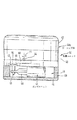
図1は、使い捨て品として形成されたポンプユニット2と、再使用するように構成された駆動ユニット3からなる調量装置1の部分断面図である。ポンプユニットのケーシング部4と駆動ユニットのケーシング部5は互いにねじ合わされている。
【0023】
ポンプユニット2のケーシング部4は中空円筒体6を有している。中空円筒体6の一方の端部は閉じていて、他方の端部は雌ねじ7を備えた固定用フランジ8を有している。円筒壁9には、円周上で互いに180度ずれて配置された2つの孔が設けられている。ここで、参照符号10で示された孔は円筒形ポンプ室12の入口を、また参照符号11で示された孔はその出口をそれぞれ形成している。チューブ導管系を接続するために、ポンプユニット2は、ケーシング部4と一体的な構成部材である、入口に接続されたルアーロック外側コーン14と、出口に接続されたルアーロック内側コーン13とを有している。ルアーロック・コネクタ、すなわちルアーロック内側コーン13とルアーロック外側コーン14は、ポンプ室12の縦方向軸線に対して直角に延びている共通の軸線上にある。
【0024】
ケーシング部4の円筒形のポンプ室12内には、調量装置の運転中に回転する排出体15が配置されている。排出体15は、差込み部材として形成されている(図4)。排出体15は円筒形の下部セクション16と、実質的に三角形断面の中央セクション17と、円筒形の上部セクション18とを有している。円筒形のポンプ室12内で、排出体15はその円筒形の上部セクション18の環状突出部19によって、この環状突出部が円筒壁9の環状突起20に引っ掛かって、滑り出ないように保持されている。三角形断面を有する中央セクション17の丸みを帯びた角隅21は、円筒壁9に密接している。さらに、排出体15は、三角形の輪郭を有する軸方向開口部22を有している。
駆動ユニット3のケーシング部5は雄ねじ24を備えた円筒形の突出部23を有している。雄ねじ24はポンプユニット2の固定用フランジ8とねじ合わせることができる。ケーシング部5は、巻上げ可能なコイルばねによって駆動されるモータ25を収容している。これは時計機構などによって知られているスプリングモータであるが、ここでは略示するにとどめる。コイルばねを巻き上げるために、ケーシングキャップ内に折り畳んで倒せるねじ頭26が設けられている。モータ25に続いて、変速比が調節可能な伝動装置27が接続されている。変速比の調節は、ケーシング部5に組み込まれたスライドスイッチ28によって行われ、3種類の回転数を設定できる。伝動装置27の駆動軸29はケーシング部の、円筒形の突出部23を通って延びており、排出体15の軸方向開口部22に対応する三角形断面を有している。両ケーシング部4、5を互いにねじ合わせると、駆動軸29は排出体の開口部22に嵌入し、トルクを排出体に伝達できる。
【0025】
図5は、栄養溶液の調量装置を用いた腸管栄養法のための装置構成を示している。この装置は栄養溶液を入れた容器29、第1のチューブ片30、調量装置1、第2のチューブ片31、およびカテーテル32を有している。カテーテル32は、患者の胃に導入されるカテーテルチューブ33を有している。カテーテルチューブ33の末端は、末端および/または側方が開いたオリーブ状体34を備えている。調量装置1の接続は、ルアーロック・コネクタ34、35によりそれぞれのチューブ端部で行われる。これらのチューブ端部は、調量装置1の、対応するルアーロック接続部材と結合している。容器29は、突き通すことが可能な膜を備えた底側の接続部材36を有している。この膜は、第1のチューブ片30のコネクタ37に組み込まれたスパイクで突き通される。第2のチューブ片31の、栄養カテーテル32との結合は、ルアーロック・コネクタ38、39によって行われる。
【0026】
運転中は調量装置1は栄養溶液を入れた容器29の下方に配置されているので、液体は重力により第1のチューブ片30を通って調量装置1のポンプ室12に流入する。回転する排出体15の回転数に依存して、栄養溶液は第2のチューブ片31を通ってカテーテルチューブ33に送られる。この場合、送り出し量は変速比を調節することによって変えることができる。
【0027】
使用後に、調量装置1の駆動ユニット3がポンプユニット2からねじをゆるめて取り外され、調量装置1と栄養チューブ、すなわち第1のチューブ片30および第2のチューブ片31との間のルアーロック・コネクタ結合が外される。その後、栄養溶液が貫流するポンプユニット2は新しいユニットと交換することができるので、清掃は必要ない。
【0028】
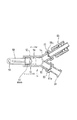
図6から図8に、調量装置の、別の構成を示す。この調量装置は、図1〜図5に基づいて説明した実施例と同様に、駆動ユニット40とポンプユニット41からなる。駆動ユニット40は実質的に円筒形のケーシング部40aを有している。ケーシング上半部は巻上げ可能なコイルばねによって駆動されるモータ42を収容している。モータ42は駆動軸44を備えた伝動装置43を有している。時計機構などによって知られているスプリングモータは、伝動装置と共に略示するにとどめる。ケーシング下半部は、ポンプユニットが固定しないで挿入されている収容スペース45を有している。収容スペース45は透明な底板46によって閉じられている。収容スペース45の上方には、縦方向に摺動可能に案内される長方形のプレート47が配置されている。プレート47は横断方向に延びたスリット48を有しており、伝動装置43の駆動軸44に嵌っている駆動輪50の突起49がこのスリット48に嵌入する。縦方向に摺動可能に案内されるプレート47の下側には円筒形のピン51が固定されている。ピン51は駆動ユニットの収容スペース45内に延びている。
【0029】
ポンプユニット41は、1つの共通脚部53と2つの分岐脚部54、55とを備えたプラスチック製のY字形のケーシング部52を有している。共通脚部53はポンプ室56を形成しており、このポンプ室56内でピストン57が摺動できる。ピストン57にはピストンロッド58が結合している。ピストンロッド58の自由な端部は円筒形の孔59を有しており、その直径はピン51の直径よりもわずかに大きい。Y字形ケーシング部の分岐脚部54、55は、ポンプユニット41の入口接続管および出口接続管を形成している。入口接続管、すなわち分岐脚部54と出口接続管、すなわち分岐脚部55には、公知の栄養装置のチューブのルアーロック・コネクタを接続するために公知のルアーロック外側コーン60とルアーロック内側コーン61がそれぞれはめ込まれている。ルアーロック外側コーン60のフランジ60aと入口接続管、すなわち分岐脚部54との間には、ディスク状の吸入弁62が配置されている。ディスク状の送り出し弁63が、ルアーロック内側コーン61のフランジ61aと出口接続管、すなわち分岐脚部55との間に取り付けられている。
【0030】
駆動ユニット40の収容スペース45は2つの平行な接触面64、65によって縁を形成されている。接触面64、65は斜めに延びている接触面66、67に接続している。ポンプユニット41は、ルアーロック外側コーン60とルアーロック内側コーン61のそれぞれのフランジ60a、61aの、互いに向き合う内側面に当接している三角形の突起68によって収容スペース45内に固定されている。この際、ルアーロック外側コーンまたはルアーロック内側コーンを備えた入口接続管、すなわち分岐脚部54と出口接続管、すなわち分岐脚部55はケーシング壁の側方開口部69、70を通って外方に延びている。
【0031】
ポンプユニット41は、プレート47のピン51がピストンロッド58の孔59内に入るように、駆動ユニット40の収容室45内に挿入されている。駆動ユニット40が運転されると、伝動装置の駆動軸44が矢印71の方向に回転して、ピン51を備えたプレート47は矢印72の方向に往復運動する。ピン51はピストンロッド58と係合しているので、ピストンロッド58も往復運動する。吸込み行程では送り出し弁63が閉じ、吸入弁62が開いてポンプ室56に液体が充填され、送り出し行程では吸入弁が閉じ、送り出し弁が開いて液体が出口接続管55に送り出される。この場合、送り出し量は液体の粘度および貯留容器の充填量にほとんど依存しない。
【0032】
調量装置の使用後、使い捨て品として形成されたポンプユニット41は駆動ユニット40の収容スペース45から取り出すことができ、新しいポンプユニットと交換できる。
【図面の簡単な説明】
【図1】 駆動ユニットがポンプユニットからねじ止めを外された、医療液体の調量装置の好ましい構成の部分断面図である。
【図2】 調量装置のポンプユニットの平面図である。
【図3】 調量装置のポンプユニットの、図1のIII−III線に沿った断面図である。
【図4】 ポンプユニットの排出体の部分断面図である。
【図5】 調量装置が栄養チューブに接続された、腸管栄養法のための装置構成を示す図である。
【図6】 調量装置の別の好ましい構成を示す図である。
【図7】 図6の調量装置を底面側から見た図である。
【図8】 調量装置のポンプユニットの部分断面図である。
【符号の説明】
1 調量装置
2 ポンプユニット
3 駆動ユニット
4,5 ケーシング部
12 ポンプ室
15 排出体
40 駆動ユニット
40a ケーシング部
41 ポンプユニット
52 ケーシング部
56 ポンプ室
57 排出体[0001]
BACKGROUND OF THE INVENTION
The present invention, medical fluid, particularly to metering apparatus nutrient solution for parenteral nutrition. Furthermore, the present invention relates to an intestinal nutrition device having such a nutrient solution metering device.
[0002]
[Prior art]
A device for metering out medical liquids, for example drugs, is known from WO 93/14797. The drug pump has a casing made of two shell-like members screwed together. These members contain compressible containers filled with medical fluid. In the casing, pressure is applied to the liquid bag by the spring-loaded plate, so that the liquid flows out of the container through the tube conduit.
[0003]
For the treatment of undernourished patients, it is known to apply to a patient a nutrient solution that exits the container through a tube and a catheter placed in the gastrointestinal tract. For long-term patients, mobile nutrition devices are used, which allow the patient to exercise almost freely, except that the patient must carry all the equipment necessary for the mobile procedure. In these instruments, a container containing a nutrient solution having a connection member to the supply device for supplying the nutrient solution, a supply device, and a tube of the supply device are inserted, and the nutrient solution is continuously supplied at a set delivery amount. And peristaltic pumps to be sent out. The advantage of a tube pump is that the medical fluid does not contact the pump components.
[0004]
[Problems to be solved by the invention]
Although this known nutritional device has a practical track record, tube pumps are disadvantageous in that they are bothersome to the patient during handling by a movable patient due to their size and relatively high weight. is there. Furthermore, the production of the tube pump involves a relatively high cost.
[0005]
An object of the present invention is to provide a compact structure that handling can be operated in a simple and low cost, the metering device of nutrient solution for medical liquids, in particular intestinal nutrition.
[0006]
[Means for Solving the Problems]
The apparatus of the present invention in order to achieve the above object, a casing unit having a pump chamber, can be separated and the casing part to each other with a driving device of the discharge member, the discharge member and a driving apparatus thereof, the casing section When the Ru abutted to each other each other initiative has a respective connecting member engaged, the drive unit as a result of its is connectable to the pump unit, or removable-der from pump unit.
[0007]
The medical liquid metering device of the present invention is not configured by a tube pump system. Feeding out the medical fluid is performed by a discharge member disposed in the pump chamber. Although the medical liquid comes into contact with the components of the metering device, no troublesome cleaning of the portion through which the liquid passes is necessary. This is because the part in contact with the liquid can be easily replaced after a single use of the device. These parts form disposable items that can be mass-produced at low cost. In contrast, the drive unit of the discharge member takes a relatively high have cost production is adapted to reuse. The discharge body may be configured as a rotary discharge body or a reciprocating discharge body, for example.
[0008]
The metering device of the present invention has two casing parts separable from each other. One casing part has a pump chamber provided with a discharge body, and the other casing part accommodates a drive unit for the discharge body. Torque is transmitted by a connecting member that engages when the drive unit is connected.
[0009]
In a preferred embodiment of the present invention, the drive unit includes a motor driven by winding possible coil spring. It's in this, metering since the device can you to drive regardless of the power supply system and battery, is in a state that you can always use. But also, a discharge body, can be driven by an electric motor driven by a battery.
[0010]
It is preferable that the drive unit has a transmission that can adjust the gear ratio so that the amount of feed can be adjusted. However, this transmission device may also be configured as a module that can be exchanged with a transmission device having a different gear ratio in order to set a smaller or larger delivery amount.
[0011]
It is preferable that both casing parts can be screwed together . To couple the casing section, for example may have a bayonet joint is provided. But also, the driving unit may be configured as a snap possible modules.
[0012]
Of the present invention, in another preferred embodiment, the pump chamber is cylindrical, the discharge member is an object rotatable pumping chamber of cylinder, the discharge member of the plurality of wings this object in close to the cylindrical wall Have. This structure is so simple that the production cost is small. Both the discharge body and the casing body can be mass-produced as a die-cast product, and can be inserted into the cylindrical pump chamber as an insertion member , after which the pump chamber is closed by a casing portion that houses the discharge body drive unit.
[0013]
In an advantageous configuration, the drive shaft of the drive unit is fitted and joined with the ejector when the drive unit is connected. Discharge member has a central opening with an inner contour, the drive shaft fits into this opening is provided with an outer contour corresponding to the inner contour of the discharge body.
[0014]
In another advantageous configuration, the discharge body is a piston slidable in a cylindrical pump chamber, the inlet and the outlet are arranged at one end of the pump chamber, and the inlet valve is arranged at the inlet A delivery valve is arranged at the outlet.
[0015]
Piston drive is carried out preferably by a slider having a reciprocable pin, when coupling the drive unit, the pin is fitted into the hole of the piston rod attached to the piston of the pump unit.
[0016]
In the above configuration, it is advantageous that the casing portion of the drive unit has an accommodation space, and the pump unit can be inserted into the accommodation space so as to be fixed in the accommodation space.
[0017]
Ke pacing unit is a tube piece Y-shaped, particularly simple and inexpensive to manufacture child when the bifurcated legs forms an inlet connection pipe and the outlet connection pipe of the pump chamber, the pump unit as a disposable door is Ru can. The Y-shaped tube piece can be easily fixed in the receiving chamber by a suitable contact surface.
[0018]
For ease of connection, the wall of the casing of the drive unit, the so accessible from outside, through holes in the region of the revenue volume space is provided in the inlet connection pipe and the outlet connection tube pump unit Is preferred .
[0019]
This metering device is conveniently used for metering nutrient solutions supplied from a container through a feeding tube to a catheter having a catheter tube introduced into the patient's stomach. In this case, the metering device is connected to the feeding tube. To connect the feeding tube end, metering connector apparatus, for example, luer lock connectors are known in the medical technology or is funnel-type connector is also used for conventional type of tubing, it is provided It is reasonable.
[0020]
Compared to the known intestinal feeding device in which the feeding of the nutrient solution is performed only by gravity, the advantage of the device in which the metering device of the present invention is connected to the feeding tube is that the feeding amount is the viscosity of the nutrient solution and the filling amount of the reservoir It is a point that is hardly dependent on There is no danger that the feeding tube will be fatigued over a long period of time and the feed rate will change with respect to a known nutritional device having a peristaltic pump. Another advantage is that during the catheter nutrition while moving, a compact structure that the patient can move more freely. Furthermore, since the pump unit can be replaced as a disposable item, it is not necessary to clean the metering device after use. Since the drive unit is reusable, the metering device can be operated inexpensively.
[0021]
DETAILED DESCRIPTION OF THE INVENTION
Embodiments of the present invention will be described below in detail with reference to the drawings.
[0022]
Figure 1 includes a
[0023]
The casing part 4 of the
[0024]
The casing portion 4 of the
The
[0025]
FIG. 5 shows an apparatus configuration for an intestinal nutrition method using a nutrient solution metering apparatus. The
[0026]
During operation, since the metering device 1 is disposed below the
[0027]
After use, the
[0028]
In FIGS. 6-8, the metering device, shows the different configurations. This metering device includes a
[0029]
[0030]
The
[0031]
The
[0032]
After use of the metering device, the
[Brief description of the drawings]
FIG. 1 is a partial cross-sectional view of a preferred configuration of a medical fluid metering device with a drive unit unscrewed from a pump unit.
FIG. 2 is a plan view of a pump unit of the metering device.
Pump unit of Figure 3 the metering device, it is a cross-sectional view taken along line III-III in FIG.
FIG. 4 is a partial cross-sectional view of a discharge body of a pump unit.
[5] the metering device is connected to a feeding tube, a diagram illustrating a device configuration for intestinal nutrition.
FIG. 6 is a diagram showing another preferred configuration of the metering device.
7 is a view of the metering device of FIG. 6 as viewed from the bottom side.
FIG. 8 is a partial cross-sectional view of a pump unit of a metering device.
[Explanation of symbols]
DESCRIPTION OF SYMBOLS 1
Claims (15)
駆動ユニット(3、40)がポンプユニット(2、41)に連結可能、または該ポンプユニットから取り外し可能であるように、前記ポンプ室(12、56)を有する前記ケーシング部(4、52)と、前記排出体の前記駆動装置(25、27;42、43)を有する前記ケーシング部(5、40a)とは互いに分離可能であり、前記排出体(15、57)とその前記駆動装置とは、前記両ケーシング部を互いに当接させると互いに係合する各連結部材(22、29;51、59)を有しており、
前記ポンプ室(12、56)を有する前記ケーシング部(4、52)と前記排出体(15、57)は、協働して、前記排出体の前記駆動装置(25、27;42、43)を有する前記ケーシング部(5、40a)と前記連結部材(22、29;51、59)を、前記医療液体から隔離している、
ことを特徴とする、医療液体の調量装置。A medical liquid having an inlet and an outlet, and having a casing portion having a pump chamber in which a discharge body that contacts and discharges the medical liquid is disposed, and a casing portion that accommodates a drive device for the discharge body , Especially in the nutritional solution metering device for enteral nutrition,
The casing part (4, 52) having the pump chamber (12, 56) so that the drive unit (3, 40) can be connected to or removed from the pump unit (2, 41); The casing part (5, 40a) having the drive device (25, 27; 42, 43) of the discharge body is separable from each other, and the discharge body (15, 57) and the drive device are separated from each other. Each of the casing members has a connecting member (22, 29; 51, 59) that engages with each other when they are brought into contact with each other .
The casing part (4, 52) having the pump chamber (12, 56) and the discharge body (15, 57) cooperate with each other to drive the discharge body (25, 27; 42, 43). Separating the casing part (5, 40a) and the connecting member (22, 29; 51, 59) from the medical fluid ,
A medical liquid metering device characterized by the above.
請求項1から13のいずれか1項に記載の、医療液体の調量装置(1)が前記栄養チューブ(30、31)に接続されていることを特徴とする栄養チューブ。The nutrient solution for enteral tube feeding method, from the container (29) containing the 該栄 nutrient solution, in feeding tube that sent to the catheter (32) having a catheter tube (33) to be introduced into the patient's stomach,
請 Motomeko according to any one of 1 to 13, feeding tube of the metering device of the medical liquid (1) is characterized in that it is connected to the nutritional tube (30, 31).
請求項1から13のいずれか1項に記載の、医療液体の調量装置(1)が前記栄養チューブ(30、31)に接続されていることを特徴とする、腸管栄養装置。In an enteral feeding device comprising a container (29) containing a nutrient solution, a feeding tube (30, 31) and a catheter (32) with a catheter tube (33) introduced into the stomach of a patient,
請 Motomeko according to any one of 1 to 13, characterized in that the metering device of the medical liquid (1) is connected before Symbol feeding tube (30, 31), intestinotrophic device.
Applications Claiming Priority (2)
| Application Number | Priority Date | Filing Date | Title |
|---|---|---|---|
| DE29701861U DE29701861U1 (en) | 1997-02-04 | 1997-02-04 | Device for dosing medical liquids |
| DE29701861-2 | 1997-02-04 |
Publications (2)
| Publication Number | Publication Date |
|---|---|
| JPH10309314A JPH10309314A (en) | 1998-11-24 |
| JP3974698B2 true JP3974698B2 (en) | 2007-09-12 |
Family
ID=8035444
Family Applications (1)
| Application Number | Title | Priority Date | Filing Date |
|---|---|---|---|
| JP2335898A Expired - Fee Related JP3974698B2 (en) | 1997-02-04 | 1998-02-04 | Medical liquid metering device |
Country Status (8)
| Country | Link |
|---|---|
| US (1) | US5993422A (en) |
| EP (1) | EP0856323B1 (en) |
| JP (1) | JP3974698B2 (en) |
| KR (1) | KR100508737B1 (en) |
| CN (1) | CN1178704C (en) |
| AR (1) | AR010884A1 (en) |
| BR (1) | BR9800541A (en) |
| DE (2) | DE29701861U1 (en) |
Families Citing this family (14)
| Publication number | Priority date | Publication date | Assignee | Title |
|---|---|---|---|---|
| KR100473363B1 (en) * | 2000-10-28 | 2005-03-07 | 김용년 | Injector |
| US8100879B2 (en) * | 2002-11-18 | 2012-01-24 | Nestec S.A. | Connector device for enteral administration set |
| US20060089604A1 (en) * | 2004-10-26 | 2006-04-27 | Intrasafe Medical, Llc | Infusion device for administering fluids to a patient |
| US8366697B2 (en) * | 2008-02-08 | 2013-02-05 | Codan Us Corporation | Enteral feeding safety reservoir and system |
| GB2474233A (en) * | 2009-10-06 | 2011-04-13 | Uk Investments Associates Llc | Cooling pump comprising a detachable head portion |
| US9710610B2 (en) | 2012-07-25 | 2017-07-18 | Covidien Lp | Enteral feeding pump with flow adjustment |
| US20140066900A1 (en) | 2012-09-06 | 2014-03-06 | Corindus, Inc. | System for guide catheter control |
| US9901725B2 (en) | 2012-10-01 | 2018-02-27 | Bayer Healthcare Llc | Overmolded medical connector tubing and method |
| EP3049127B1 (en) | 2013-09-24 | 2021-07-14 | Kpr U.S., Llc | Feeding set and enteral feeding pump |
| CN104307054B (en) * | 2014-10-08 | 2016-06-22 | 常熟市雷号医疗器械有限公司 | Medical semi-automatic drainage metering device |
| DE102014226310A1 (en) * | 2014-12-17 | 2016-06-23 | Hamilton Bonaduz Ag | Liquid metering device with modular design, in particular with change gear |
| WO2017060445A1 (en) * | 2015-10-09 | 2017-04-13 | Fresenius Kabi Deutschland Gmbh | Cover for a container for receiving an enteral nutrition solution |
| CN106691865B (en) * | 2017-01-16 | 2023-05-26 | 郑州大学第一附属医院 | Spiral negative pressure extraction booster |
| US11266574B2 (en) | 2018-08-27 | 2022-03-08 | Avent, Inc. | Blenderized diet and/or bolus delivery manual pump |
Family Cites Families (31)
| Publication number | Priority date | Publication date | Assignee | Title |
|---|---|---|---|---|
| DE1026047B (en) * | 1952-09-18 | 1958-03-13 | Dr Med Dietrich Sachs | Device for pumping blood |
| US3447479A (en) * | 1967-06-02 | 1969-06-03 | Pall Corp | Syringe pump |
| DE2112654A1 (en) * | 1971-03-16 | 1972-10-05 | Southdown Medical Developments | Device for actuating a syringe |
| JPS4913705A (en) * | 1972-05-18 | 1974-02-06 | ||
| DE2408912B2 (en) * | 1974-02-25 | 1976-09-02 | Regelsberger, Helmut, Dr.flied., 4930 Detmold | METHOD FOR DELIVERING GASES IN PORTIONS INTO THE VEIN SYSTEM OF A HUMAN OR ANIMAL, AND DEVICE FOR CARRYING OUT THE METHOD |
| DE2639992A1 (en) * | 1976-09-04 | 1978-03-09 | Sigdell Jan Erik Dr | Infusion pump and flow meter - has single diaphragm for pump and inlet and outlet valves |
| US4634431A (en) * | 1976-11-12 | 1987-01-06 | Whitney Douglass G | Syringe injector |
| ES234032Y (en) * | 1978-02-17 | 1979-01-01 | PUMPING DEVICE FOR INFUSIONS IN MEDICAL APPLICATIONS | |
| US4450079A (en) * | 1979-09-06 | 1984-05-22 | Imed Corporation | Cassette for providing a controlled flow of fluid |
| DE3106611A1 (en) * | 1980-03-03 | 1982-01-28 | Andros Inc., Berkeley, Calif. | "MEDICAL INFUSION DEVICE, IN PARTICULAR INTERCHANGEABLE PUMP CASSETTE DAFUER" |
| US4396305A (en) * | 1981-01-22 | 1983-08-02 | Scm Corporation | Ribbon Cartridge handling apparatus |
| DE3138267C2 (en) * | 1981-09-25 | 1985-05-30 | Pfrimmer-Viggo GmbH & Co KG, 8520 Erlangen | Enteral feeding device |
| US4636431A (en) * | 1983-02-25 | 1987-01-13 | E. I. Du Pont De Nemours And Company | Polymers containing resorcinol monobenzoate |
| US4605396A (en) * | 1985-02-25 | 1986-08-12 | Warner-Lambert Company | Gravity flow cassette with rotary valve |
| DE3611112A1 (en) * | 1986-01-10 | 1987-07-16 | Fresenius Ag | NUTRITIONAL SYSTEM FOR ENTERAL NUTRITION |
| US4798589A (en) * | 1987-06-15 | 1989-01-17 | Fisher Scientific Group Inc. | Diaphragm pump cassette |
| ATE115866T1 (en) * | 1987-06-16 | 1995-01-15 | Frantz Medical Dev Ltd | PUMP, ESPECIALLY FOR CONTROL OF ENTERAL FLUID, PUMP CASSETTE, AND OPERATING PROCEDURES. |
| JPH0438149Y2 (en) * | 1987-12-01 | 1992-09-07 | ||
| JPH01218461A (en) * | 1988-02-27 | 1989-08-31 | Nippon Zeon Co Ltd | Liquid transporter |
| JPH0451964A (en) * | 1990-06-16 | 1992-02-20 | Mitsubishi Kasei Corp | Fluid therapy device |
| JPH05115551A (en) * | 1991-10-30 | 1993-05-14 | Sadayuki Yamada | Pulsating blood transporting device in surgery |
| ATE237378T1 (en) * | 1992-01-24 | 2003-05-15 | I Flow Corp | PUMP WITH PRESSURE PLATE |
| US5911716A (en) * | 1992-01-24 | 1999-06-15 | I-Flow Corporation | Platen pump |
| JP3332245B2 (en) * | 1992-07-06 | 2002-10-07 | アークレイ株式会社 | Control method of liquid pump used for high performance liquid chromatography |
| DE4336336A1 (en) * | 1992-11-23 | 1994-05-26 | Lang Volker | Cassette infusion system |
| JPH07100206A (en) * | 1993-10-06 | 1995-04-18 | Nissho Corp | Fixed pressure liquid chemical injecting pump |
| US5827219A (en) * | 1993-10-28 | 1998-10-27 | Medrad, Inc. | Injection system and pumping system for use therein |
| JPH07194695A (en) * | 1993-12-28 | 1995-08-01 | Jms Co Ltd | Fluid transferring device |
| US5492535A (en) * | 1994-04-06 | 1996-02-20 | Cordis Corporation | Hand-powered pumping apparatus for perfusion and other fluid catheterization procedures |
| JP3069253B2 (en) * | 1994-11-22 | 2000-07-24 | シルバー株式会社 | Electromagnetic pump with oil level sensor |
| US5656034A (en) * | 1995-03-31 | 1997-08-12 | Perkin Elmer Corp | High-pressure micro-volume syringe pump |
-
1997
- 1997-02-04 DE DE29701861U patent/DE29701861U1/en not_active Expired - Lifetime
-
1998
- 1998-01-25 CN CNB981043097A patent/CN1178704C/en not_active Expired - Fee Related
- 1998-01-31 DE DE59806570T patent/DE59806570D1/en not_active Expired - Lifetime
- 1998-01-31 EP EP19980101669 patent/EP0856323B1/en not_active Expired - Lifetime
- 1998-02-03 BR BR9800541A patent/BR9800541A/en not_active IP Right Cessation
- 1998-02-03 US US09/017,845 patent/US5993422A/en not_active Expired - Lifetime
- 1998-02-04 KR KR10-1998-0003002A patent/KR100508737B1/en not_active IP Right Cessation
- 1998-02-04 JP JP2335898A patent/JP3974698B2/en not_active Expired - Fee Related
- 1998-02-04 AR ARP980100487 patent/AR010884A1/en active IP Right Grant
Also Published As
| Publication number | Publication date |
|---|---|
| US5993422A (en) | 1999-11-30 |
| CN1178704C (en) | 2004-12-08 |
| KR100508737B1 (en) | 2005-12-06 |
| CN1190024A (en) | 1998-08-12 |
| EP0856323B1 (en) | 2002-12-11 |
| DE59806570D1 (en) | 2003-01-23 |
| AR010884A1 (en) | 2000-07-12 |
| DE29701861U1 (en) | 1998-06-10 |
| EP0856323A2 (en) | 1998-08-05 |
| KR19980071043A (en) | 1998-10-26 |
| BR9800541A (en) | 1999-07-06 |
| EP0856323A3 (en) | 1998-12-16 |
| JPH10309314A (en) | 1998-11-24 |
Similar Documents
| Publication | Publication Date | Title |
|---|---|---|
| JP3974698B2 (en) | Medical liquid metering device | |
| US10398831B2 (en) | Positive displacement pump | |
| US4936760A (en) | Volumetric infusion pump | |
| CN109789251B (en) | Device for aspirating body fluids and for delivering substances | |
| EP0555007B1 (en) | Drug delivery system | |
| CN106691865B (en) | Spiral negative pressure extraction booster | |
| US20050020980A1 (en) | Coupling system for an infusion pump | |
| CN109715229B (en) | Suction and delivery device with drive unit and connecting piece | |
| US20060226086A1 (en) | Centrifuge for blood processing systems | |
| WO2002025112A1 (en) | Flexible tube positive displacement pump | |
| WO2010078073A1 (en) | Reservoir compartment adapter for infusion device | |
| WO2008098190A1 (en) | Enteral feeding systems, devices and methods | |
| US8529512B2 (en) | Cylinder pump | |
| WO1991016933A1 (en) | Disposable infusion apparatus with peristaltic pump | |
| DE3852523T2 (en) | Pump, especially for the control of the enterally administered liquid, pump cassette, and operating procedures. | |
| MXPA98000970A (en) | Device for the dosage of medicine liquids | |
| CN111184928A (en) | External nutrient solution transfusion assembly | |
| CN110841125A (en) | Peritoneal dialysis solution supply system | |
| EP1888246A1 (en) | Centrifuge for blood processing systems | |
| CN218979770U (en) | Hydrostatic therapy liquid dispenser | |
| CN221431899U (en) | Stomach intestine medicine feeder | |
| LU500040B1 (en) | Intelligent dispensing device | |
| CN212490990U (en) | External nutrient solution transfusion assembly | |
| JP7431424B2 (en) | cylinder pump | |
| US20230108800A1 (en) | Infusion pump with multiple reservoirs |
Legal Events
| Date | Code | Title | Description |
|---|---|---|---|
| A521 | Written amendment |
Free format text: JAPANESE INTERMEDIATE CODE: A821 Effective date: 19980206 |
|
| A521 | Written amendment |
Free format text: JAPANESE INTERMEDIATE CODE: A523 Effective date: 19980529 |
|
| RD04 | Notification of resignation of power of attorney |
Free format text: JAPANESE INTERMEDIATE CODE: A7424 Effective date: 20000216 |
|
| A521 | Written amendment |
Free format text: JAPANESE INTERMEDIATE CODE: A523 Effective date: 20050204 |
|
| A621 | Written request for application examination |
Free format text: JAPANESE INTERMEDIATE CODE: A621 Effective date: 20050204 |
|
| RD04 | Notification of resignation of power of attorney |
Free format text: JAPANESE INTERMEDIATE CODE: A7424 Effective date: 20050204 |
|
| A977 | Report on retrieval |
Free format text: JAPANESE INTERMEDIATE CODE: A971007 Effective date: 20060712 |
|
| A131 | Notification of reasons for refusal |
Free format text: JAPANESE INTERMEDIATE CODE: A131 Effective date: 20060823 |
|
| A601 | Written request for extension of time |
Free format text: JAPANESE INTERMEDIATE CODE: A601 Effective date: 20061124 |
|
| A602 | Written permission of extension of time |
Free format text: JAPANESE INTERMEDIATE CODE: A602 Effective date: 20061204 |
|
| A521 | Written amendment |
Free format text: JAPANESE INTERMEDIATE CODE: A523 Effective date: 20070222 |
|
| RD03 | Notification of appointment of power of attorney |
Free format text: JAPANESE INTERMEDIATE CODE: A7423 Effective date: 20070222 |
|
| A521 | Written amendment |
Free format text: JAPANESE INTERMEDIATE CODE: A821 Effective date: 20070222 |
|
| TRDD | Decision of grant or rejection written | ||
| A01 | Written decision to grant a patent or to grant a registration (utility model) |
Free format text: JAPANESE INTERMEDIATE CODE: A01 Effective date: 20070516 |
|
| A61 | First payment of annual fees (during grant procedure) |
Free format text: JAPANESE INTERMEDIATE CODE: A61 Effective date: 20070615 |
|
| R150 | Certificate of patent or registration of utility model |
Free format text: JAPANESE INTERMEDIATE CODE: R150 |
|
| FPAY | Renewal fee payment (event date is renewal date of database) |
Free format text: PAYMENT UNTIL: 20100622 Year of fee payment: 3 |
|
| FPAY | Renewal fee payment (event date is renewal date of database) |
Free format text: PAYMENT UNTIL: 20110622 Year of fee payment: 4 |
|
| FPAY | Renewal fee payment (event date is renewal date of database) |
Free format text: PAYMENT UNTIL: 20120622 Year of fee payment: 5 |
|
| FPAY | Renewal fee payment (event date is renewal date of database) |
Free format text: PAYMENT UNTIL: 20130622 Year of fee payment: 6 |
|
| LAPS | Cancellation because of no payment of annual fees |