JP3973390B2 - Intake pressure detection method for internal combustion engine - Google Patents
Intake pressure detection method for internal combustion engine Download PDFInfo
- Publication number
- JP3973390B2 JP3973390B2 JP2001296775A JP2001296775A JP3973390B2 JP 3973390 B2 JP3973390 B2 JP 3973390B2 JP 2001296775 A JP2001296775 A JP 2001296775A JP 2001296775 A JP2001296775 A JP 2001296775A JP 3973390 B2 JP3973390 B2 JP 3973390B2
- Authority
- JP
- Japan
- Prior art keywords
- intake pressure
- value
- internal combustion
- combustion engine
- lower limit
- Prior art date
- Legal status (The legal status is an assumption and is not a legal conclusion. Google has not performed a legal analysis and makes no representation as to the accuracy of the status listed.)
- Expired - Fee Related
Links
- 238000002485 combustion reaction Methods 0.000 title claims description 97
- 238000001514 detection method Methods 0.000 title claims description 68
- 230000010349 pulsation Effects 0.000 claims description 66
- 230000001052 transient effect Effects 0.000 claims description 34
- 238000000034 method Methods 0.000 claims description 17
- 239000000446 fuel Substances 0.000 description 56
- 238000002347 injection Methods 0.000 description 36
- 239000007924 injection Substances 0.000 description 36
- 230000001133 acceleration Effects 0.000 description 22
- 230000000875 corresponding effect Effects 0.000 description 19
- 230000001788 irregular Effects 0.000 description 14
- 230000008569 process Effects 0.000 description 10
- 230000004043 responsiveness Effects 0.000 description 9
- 238000012937 correction Methods 0.000 description 7
- 238000012545 processing Methods 0.000 description 7
- 230000001276 controlling effect Effects 0.000 description 6
- 230000007423 decrease Effects 0.000 description 6
- 238000009499 grossing Methods 0.000 description 6
- 239000000203 mixture Substances 0.000 description 6
- 230000000630 rising effect Effects 0.000 description 6
- 230000008859 change Effects 0.000 description 5
- 230000000694 effects Effects 0.000 description 5
- 239000007789 gas Substances 0.000 description 5
- 239000001301 oxygen Substances 0.000 description 5
- 229910052760 oxygen Inorganic materials 0.000 description 5
- 230000004044 response Effects 0.000 description 5
- 230000007704 transition Effects 0.000 description 5
- 238000012935 Averaging Methods 0.000 description 4
- 101150096038 PTH1R gene Proteins 0.000 description 4
- QVGXLLKOCUKJST-UHFFFAOYSA-N atomic oxygen Chemical compound [O] QVGXLLKOCUKJST-UHFFFAOYSA-N 0.000 description 4
- 239000000498 cooling water Substances 0.000 description 4
- 230000006870 function Effects 0.000 description 4
- 238000000137 annealing Methods 0.000 description 3
- 230000002596 correlated effect Effects 0.000 description 3
- 238000010586 diagram Methods 0.000 description 3
- XLYOFNOQVPJJNP-UHFFFAOYSA-N water Substances O XLYOFNOQVPJJNP-UHFFFAOYSA-N 0.000 description 3
- 239000002826 coolant Substances 0.000 description 2
- 239000002828 fuel tank Substances 0.000 description 2
- 239000003054 catalyst Substances 0.000 description 1
- 230000003247 decreasing effect Effects 0.000 description 1
- 230000003111 delayed effect Effects 0.000 description 1
- 238000000691 measurement method Methods 0.000 description 1
- 150000002926 oxygen Chemical class 0.000 description 1
- 230000029058 respiratory gaseous exchange Effects 0.000 description 1
- 238000005070 sampling Methods 0.000 description 1
Images


Landscapes
- Combined Controls Of Internal Combustion Engines (AREA)
- Electrical Control Of Air Or Fuel Supplied To Internal-Combustion Engine (AREA)
- Measuring Fluid Pressure (AREA)
- Electrical Control Of Ignition Timing (AREA)
Description
【0001】
【発明の属する技術分野】
この発明は、内燃機関の制御に必要な運転パラメータとして使用される吸気圧を検出するための吸気圧検出方法、並びにその吸気圧検出方法の実施に直接使用する吸気圧検出装置及び内燃機関の制御装置に関する。
【0002】
【従来の技術】
従来より、内燃機関の吸気圧は、燃料噴射制御、点火時期制御又は排気還流制御等の種々の内燃機関の制御に運転パラメータの一つとして使用されている。例えば、いわゆる「D−Jシステム」(吸気通路の吸気圧を測定して燃料噴射を行うシステム)のエンジンでは、エンジンの燃焼室に吸入される吸気量を、吸気圧とエンジン回転速度から算出し、算出された吸気量に基づいて燃料噴射量を求めている。しかし、レシプロエンジンでは、ピストンの往復運動に伴い吸気に脈動が発生することから、吸気圧もそれに伴って変動することになる。このため、吸気圧センサで検出される吸気圧の値をそのまま運転パラメータとして使用することは、内燃機関の制御が不安定となるためできなかった。
【0003】
そこで、吸気脈動の影響を排除した吸気圧を検出して内燃機関の制御に使用するために、種々の技術がこれまで提案されている。
【0004】
一般的な技術としては、吸気圧センサによる検出値を「なまし処理」することにより、吸気の脈動に伴う吸気圧の変動を平滑化することが考えられる。「なまし処理」とは、所定の周期でサンプリングされる検出値を平均化処理することであり、その平均化度合いを「なまし係数」として任意に設定することができる。
【0005】
この他、特開平1−318938号公報にも同様の技術の一例が開示されている。即ち、この公報の吸気管圧力計測装置では、吸気圧センサにより検出される吸気圧を所定の駆動周期毎にサンプリングし、そのサンプリングで得られる吸気圧の検出値を相加平均処理して平均値を演算する。そして、内燃機関の過渡運転時には、この平均値をそのまま吸気圧の計算値として燃料噴射量の制御に使用する。一方で、内燃機関の定常運転時には、上記の相加平均処理により得られた平均値を更に平均化し、その平均化で得られる平均値をそのまま吸気圧の計算値として燃料噴射量の制御に使用するようにしている。即ち、この計測装置では、過渡運転時には、吸気圧センサの検出値を「1回なまし処理」することにより得られる計算値を吸気圧とし、定常運転時には、吸気圧センサの検出値を「2回なまし処理」することにより得られる計算値を吸気圧として、それぞれ燃料噴射量制御に使用している。
【0006】
【発明が解決しようとする課題】
ところが、従来の一般的な「なまし処理」による計測方法では、なまし係数を大きくすると、吸気圧の計算値は、定常運転時には安定するものの、過渡運転時には応答遅れが生じる傾向があった。逆に、なまし係数を小さくすると、吸気圧の計算値は、過渡運転時の応答遅れは改善されるものの、定常運転時にかえって不安定になる傾向があった。
【0007】
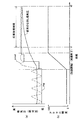
一方、前記従来公報の計測装置では、図13に示すように、吸気圧の計算値は、定常運転時に安定し、過渡運転時の応答性も前記一般的なまし処理に比べて改善されることになる。しかしながら、計算値の精度としては、実際に燃焼室に取り込まれる吸気量との相関性が充分ではなく、内燃機関の負荷に対する吸気圧計算値の関係では、リニアリティのある特性が得られなかった。
【0008】
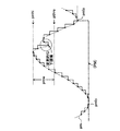
ここで、本願出願人は、4サイクルのレシプロエンジンで、吸気の脈動に伴う吸気圧の変動において、その吸気圧の下限値、即ち、吸気行程の下死点付近での検出値が、実際の吸気量を最も良く反映した吸気圧となることを発見し、これを吸気圧の計算値として使用することを考え出し、特願2000−293439の出願で既に提案している。即ち、内燃機関の運転時に、図14に示すように、脈動を伴って変化する吸気圧のAD値pmadの下限値pmloを算出し、その下限値pmloを吸気圧の検出値としての最終的な吸気圧PMとする内燃機関の吸気圧検出方法を提案している。
【0009】
この提案技術につき、本出願人が更に検討を重ねた結果、運転中のエンジンで吹き返しなどが発生し、図14に時刻t1,t2で示すように、AD値pmadの波形が乱れた場合、その乱れによる変則的な下限値を吸気圧脈動の下限値pmloとして誤検出してしまうおそれがあることが分かった。このような誤検出が起きた場合、エンジンの吸入空気量は実際よりも多い値として算出され、それに応じて燃料噴射量が過剰に算出されることから、空燃比がリッチ化して、ドライバビリティや排気エミッションを悪化させるなどの不具合を発生させるおそれがある。
【0010】
そこで、この発明は上記事情に鑑みてなされたものであって、その目的は、安定性と応答性に優れ、実際の吸気量との相関性の高い吸気圧の検出を可能にすると共に、エンジン吹き返しなどによる誤検出を防止することを可能にした内燃機関の吸気圧検出方法を提供することにある。
【0011】
【課題を解決するための手段】
上記目的を達成するために、請求項1に記載の発明の内燃機関の吸気圧検出方法は、内燃機関の制御に使用される吸気圧を検出するようにした内燃機関の吸気圧検出方法であって、内燃機関の運転時に吸気圧脈動を吸気圧検出手段により検出し、その検出値における下限値を算出すると共に、内燃機関の回転速度に応じたしきい値を算出し、そのしきい値より下限値が小さくなるとき下限値を制御に使用される吸気圧の最終的な検出値として決定することを趣旨とする。
【0012】
内燃機関の運転時には、吸気に脈動が発生して吸気圧も脈動を伴うことから、この吸気圧を内燃機関の制御のためにそのまま使用したのでは、その制御が不安定になる。ここで、吸気圧脈動の検出値において、その下限値が実際の吸気量を最も良く反映した吸気圧となることが既に発見されている。
従って、上記発明の構成によれば、吸気圧脈動の下限値が算出され、その算出される下限値が制御に使用される吸気圧の最終的な検出値として決定されることから、脈動を伴う吸気圧にも拘わらず、吸気圧として吸気量に相関した適正な値と挙動が得られる。
又、内燃機関の回転速度に応じて算出されるしきい値より下限値が小さくなるときその下限値が制御に使用される吸気圧の最終的な検出値として決定されるので、例えば、内燃機関の吹き返しなどにより、吸気圧脈動の波形が乱れて変則的な下限値が現れても、その変則的な下限値が除外されて吸気圧の最終的な検出値として決定されることがない。
【0013】
上記目的を達成するために、請求項2に記載の発明は、請求項1に記載の発明の内燃機関の吸気圧検出方法において、しきい値は、下限値と共に算出される吸気圧脈動の上限値から所定の設定幅を減算することにより算出されるものであり、その設定幅は、内燃機関の高負荷定常運転時における回転速度に応じた吸気圧脈動の振幅に基づき予め設定されたものであることを趣旨とする。
【0014】
上記発明の構成によれば、請求項1に記載の発明の作用に加え、しきい値は、吸気圧脈動の上限値を基準にその上限値より設定幅だけ低い値として算出される。ここで、上記設定幅は、内燃機関の高負荷定常運転時における回転速度に応じた吸気圧脈動の振幅に基づいて設定されることから、回転速度により変わる下限値との比較に好適なしきい値が得られる。
【0015】
上記目的を達成するために、請求項3に記載の発明は、請求項1に記載の発明の内燃機関の吸気圧検出方法において、内燃機関の過渡運転時には、回転速度に応じて算出されるしきい値より大きい別のしきい値を算出し、その別のしきい値より下限値が小さくなるときその下限値を吸気圧の最終的な検出値として決定することを趣旨とする。
【0016】
内燃機関の過渡運転時には、吸気圧脈動の振幅が定常運転時のそれに比べて小さくなり、その下限値が相対的に大きくなることから、下限値がしきい値より大きくなる傾向がある。そこで、上記発明の構成によれば、請求項1に記載の発明の作用に加え、内燃機関の過渡運転時には、しきい値より大きい別のしきい値が下限値との比較に参照され、その別のしきい値より下限値が小さくなるとき下限値が吸気圧の最終的な検出値として決定されるので、過渡運転時に対応して吸気圧の検出を行うことが可能となる。
【0017】
上記目的を達成するために、請求項4に記載の発明の内燃機関の吸気圧検出装置は、内燃機関の制御に使用される吸気圧を検出するようにした内燃機関の吸気圧検出装置であって、内燃機関の吸気圧を検出するための吸気圧検出手段と、内燃機関の運転時に吸気圧検出手段により検出される吸気圧脈動の検出値における下限値を算出するための下限値算出手段と、内燃機関の回転速度を検出するための回転速度検出手段と、検出される回転速度に応じたしきい値を算出するためのしきい値算出手段と、しきい値より下限値が小さくなるとき下限値を制御に使用される吸気圧の最終的な検出値として決定するための吸気圧決定手段とを備えたことを趣旨とする。
【0018】
上記発明の構成によれば、内燃機関の運転時に吸気圧検出手段による検出値に基づいて、下限値算出手段により吸気圧脈動の検出値における下限値が算出されると共に、回転速度検出手段により検出される回転速度に応じたしきい値がしきい値算出手段により算出される。そして、そのしきい値より下限値が小さくなるとき、吸気圧決定手段により下限値が吸気圧の最終的な検出値として決定されることから、脈動を伴う吸気圧にも拘わらず吸気圧として吸気量に相関した適正な値と挙動が得られる。又、内燃機関の吹き返しなどにより吸気圧脈動の波形が乱れて、変則的な下限値が現れても、その変則的な下限値が除外されて吸気圧の最終的な検出値として決定されることがない。
【0019】
上記目的を達成するために、請求項5に記載の発明は、請求項4に記載の発明の内燃機関の吸気圧検出装置において、内燃機関の過渡運転を判断するための過渡運転判断手段と、内燃機関の過渡運転に応じたしきい値であってしきい値より大きい別のしきい値を算出するための別のしきい値算出手段とを備え、吸気圧決定手段は、内燃機関の過渡運転と判断されたときに、しきい値算出手段により算出されるしきい値に代わって別のしきい値算出手段により算出される別のしきい値を選択し、その別のしきい値より下限値が小さくなるとき下限値を吸気圧の最終的な検出値として決定することを趣旨とする。
【0020】
内燃機関の過渡運転時には、吸気圧脈動の振幅が定常運転時のそれに比べて小さくなり、その下限値も相対的に大きくなることから、下限値がしきい値より大きくなる傾向がある。そこで、上記発明の構成によれば、請求項4に記載の発明の作用に加え、内燃機関の過渡運転時には、過渡運転時判断手段によりそのことが判断され、別のしきい値算出手段により算出され、しきい値算出手段により算出されるしきい値より大きい別のしきい値が下限値との比較に参照され、その別のしきい値より下限値が小さくなるとき下限値が吸気圧の最終的な検出値として吸気圧決定手段により決定されるので、過渡運転時に対応して吸気圧の検出を行うことが可能になる。
【0021】
上記目的を達成するために、請求項6に記載の発明は、内燃機関の運転に関わる制御対象を制御するようにした制御装置において、内燃機関の吸気圧を検出するための吸気圧検出手段と、内燃機関の回転速度を検出するための回転速度検出手段と、内燃機関の運転時に吸気圧検出手段により検出される吸気圧脈動の検出値に係る下限値を算出するための下限値算出手段と、検出される回転速度に応じたしきい値を算出するためのしきい値算出手段と、しきい値より下限値が小さくなるとき下限値を制御に使用される吸気圧の最終的な検出値として決定するための吸気圧決定手段と、決定される吸気圧の最終的な検出値と回転速度の検出値とに基づいて所要の制御量を得るための操作量を算出する操作量算出手段と、算出される操作量に基づいて制御対象を操作することにより制御量を制御するための制御手段とを備えたことを趣旨とする。
【0022】
上記発明の構成によれば、内燃機関の運転時に、吸気圧検出手段により検出される吸気圧の検出値から、吸気圧脈動の下限値が下限値算出手段により算出される。同じく、運転時に、回転速度検出手段により検出される回転速度に応じたしきい値がしきい値算出手段により算出される。そして、しきい値より下限値が小さくなるとき、その下限値が吸気圧の最終的な検出値として吸気圧決定手段により決定される。ここで、決定された吸気圧の最終的な検出値と回転速度の検出値とに基づいて、操作量算出手段により所要の制御量を得るための操作量が算出され、制御手段により、その操作量に基づき制御対象が操作されることにより制御量が制御される。
従って、吸気圧脈動の乱れによる変則的な下限値が除外されて吸気圧の検出値として決定されることがなく、適正な吸気圧脈動の下限値のみが吸気圧の検出値として制御対象の制御に取り込まれる。これにより、脈動を伴う吸気圧にも拘わらず制御量が不安定な値となることがなく、制御対象が吸気圧の挙動に応じて適正に制御される。
【0023】
【発明の実施の形態】
以下、本発明の内燃機関の吸気圧検出方法及びその検出方法を使用した吸気圧検出装置、その吸気圧検出装置を使用した内燃機関の制御装置を具体化した一実施の形態を図面を参照して詳細に説明する。
【0024】
図1に、本実施の形態のエンジンシステムの概略構成を示す。車両に搭載されたエンジンシステムは燃料を貯留する燃料タンク1を備える。燃料タンク1に内蔵された燃料ポンプ2は、タンク1に貯留された燃料を吐出する。内燃機関であるレシプロタイプの単気筒エンジン3には、燃料噴射弁(インジェクタ)4が設けられる。燃料ポンプ2から吐出された燃料は、燃料通路5を通じてインジェクタ4に供給される。供給された燃料は、インジェクタ4が作動することにより、吸気通路6へ噴射される。吸気通路6には、エアクリーナ7を通じて外部から空気が取り込まれる。吸気通路6に取り込まれた空気とインジェクタ4から噴射された燃料は、可燃混合気を形成して燃焼室8に吸入される。
【0025】
吸気通路6には、所定のアクセル装置(図示略)により操作されるスロットルバルブ9が設けられる。スロットルバルブ9が開閉されることにより、吸気通路6から燃焼室8に吸入される空気量(吸気量)が調節される。吸気通路6には、スロットルバルブ9を迂回してバイパス通路10が設けられる。バイパス通路10には、アイドル・スピード・コントロール・バルブ(ISCバルブ)11が設けられる。ISCバルブ11は、アイドル運転時、即ち、スロットルバルブ9の全閉時に、エンジン3のアイドル回転速度を調節するために作動させるものである。
【0026】
燃焼室8に設けられた点火プラグ12は、イグニッションコイル13から出力される点火信号を受けてスパーク動作する。両部品12,13は、燃焼室8に供給される可燃混合気に点火するための点火装置を構成する。燃焼室8に吸入された可燃混合気は、点火プラグ12のスパーク動作により爆発・燃焼する。燃焼後の排気ガスは、燃焼室8から排気通路14を通じて外部へ排出される。排気通路14を流れる排気ガスは、三元触媒15により浄化される。そして、燃焼室8における可燃混合気の燃焼に伴い、ピストン16が運動してクランクシャフト17が回転することにより、車両を走行させる駆動力がエンジン3で得られる。
【0027】
車両には、エンジン3を始動させるためのイグニションスイッチ18が設けられる。車両には、エンジン3の各種制御を司る電子制御装置(ECU)20が設けられる。車両用電源としてのバッテリ19は、イグニションスイッチ18を介してECU20に接続される。イグニションスイッチ18がオンされることにより、バッテリ19からECU20に電力が供給される。
【0028】
エンジン3に設けられる各種センサ21,22,23,24は、エンジン3の運転状態に関する各種運転パラメータを検出するためのものであり、それぞれECU20に接続される。即ち、吸気通路6に設けられた吸気圧検出手段である吸気圧センサ21は、スロットルバルブ9より下流側の吸気通路6における吸気圧pmを検出し、その検出値に応じた電気信号を出力する。エンジン3に設けられた水温センサ22は、エンジン3の内部を流れる冷却水の温度(冷却水温)THWを検出し、その検出値に応じた電気信号を出力する。エンジン3に設けられた回転速度検出手段である回転速度センサ23は、クランクシャフト17の回転速度(エンジン回転速度)NEを検出し、その検出値に応じた電気信号を出力する。排気通路14に設けられた酸素センサ24は、排気通路14へ排出される排気ガス中の酸素濃度(出力電圧)Oxを検出し、その検出値に応じた電気信号を出力する。この酸素センサ24は、エンジン3の燃焼室8に供給される可燃混合気の空燃比A/Fを得るために使用される。
【0029】
この実施の形態で、ECU20は、前述した各種センサ21〜24から出力される各種信号を入力する。ECU20は、これらの入力信号に基づき、吸気圧検出制御、燃料噴射制御及び点火時期制御等をそれぞれ実行するために、燃料ポンプ2、インジェクタ4、ISCバルブ11及びイグニションコイル13等をそれぞれ制御する。この実施の形態で、ECU20は、本発明の下限値算出手段、しきい値算出手段、吸気圧決定手段、過渡運転判断手段、別のしきい値算出手段、操作量算出手段及び制御手段を構成する。
【0030】
ここで、吸気圧検出制御とは、吸気圧センサ21で検出される吸気圧pmに基づいて吸気脈動の影響を排除した吸気圧の検出値を得るための制御である。燃料噴射制御とは、エンジン3の運転状態に応じてインジェクタ4による燃料噴射量及びその噴射タイミングを制御することである。点火時期制御とは、エンジン3の運転状態に応じてイグニションコイル13を制御することにより、各点火プラグ12による点火時期を制御することである。
【0031】
周知のように、ECU20は中央処理装置(CPU)、読み出し専用メモリ(ROM)、ランダムアクセスメモリ(RAM)、バックアップRAM、外部入力回路及び外部出力回路等を備える。ECU20は、CPU、ROM、RAM及びバックアップRAMと、外部入力回路及び外部出力回路等とをバスにより接続してなる論理演算回路を構成する。ROMは、エンジン3の各種制御に関する所定の制御プログラムを予め記憶したものである。RAMは、CPUの演算結果を一時記憶するものである。バックアップRAMは、予め記憶したデータを保存するものである。CPUは、入力回路を介して入力される各種センサ21〜24の検出信号に基づき、所定の制御プログラムに従って前述した各種制御等を実行する。
【0032】
次に、ECU20が実行する各種制御のうち、吸気圧検出制御のための処理内容について説明する。図2に吸気圧検出制御プログラムをフローチャートに示す。ECU20は、図2に示すルーチンを所定期間毎に周期的に実行する。この実施の形態では、ECU20は「1ms」の周期でこのルーチンを実行する。
【0033】
先ず、ステップ100で、ECU20は、回転速度センサ23の検出値に基づきエンジン回転速度NEの値を読み込む。
【0034】
次に、ステップ101で、ECU20は、吸気圧センサ21で検出される吸気圧pmについて今回のAD値pmadを読み込む。
【0035】
次に、ステップ102で、ECU20は、今回のAD値pmadが前回のAD値pmadoより大きいか否かを判断する。この判断結果が否定である場合、吸気圧pmが上昇していないものとして、ステップ118で、ECU20は、今回の圧力上昇フラグXPMUPを「0」に設定し、処理をステップ119へ移行する。圧力上昇フラグXPMUPとは、吸気圧pmが上昇している場合に「1」に設定され、それ以外の場合には「0」に設定されるものである。
【0036】
ステップ119では、ECU20は、前回の圧力上昇フラグXPMUPOが「1」であるか否かを判断する。この判断結果が否定である場合、吸気圧pmが前回に引き続いて降下しているものとして、ECU20は、処理をステップ114へ移行する。この判断結果が肯定である場合、吸気圧pmが上昇から下降に転じたものとして、ステップ120で、ECU20は、前回のAD値pmadoを上限値pmhiとして設定し、処理をステップ114へ移行する。
【0037】
一方、ステップ102の判断結果が肯定である場合、吸気圧pmが上昇しているものとして、ステップ103で、ECU20は、今回の圧力上昇フラグXPMUPを「1」に設定する。
【0038】
次に、ステップ104で、ECU20は、前回の圧力上昇フラグXPMUPOが「0」であるか否かを判断する。この判断結果が否定である場合、吸気圧pmが前回に引き続いて上昇しているものとして、ECU20は処理をステップ114へ移行する。上記判断結果が肯定である場合、吸気圧pmが下降から上昇に転じたものとして、処理をステップ105へ移行する。
【0039】
ステップ105で、ECU20は、減速判定フラグXGENSOKUが「0」であるか否かを判断する。減速判定フラグXGENSOKUは、エンジン3の減速運転時に「1」に設定され、それ以外の場合に「0」に設定されるものである。この実施の形態では、ECU20は、本ルーチンによって得られる後述する最終的な吸気圧PMの値の変化と、回転速度センサ23の検出値の変化等に基づいてエンジン3が減速運転状態にあるか否かを判断し、その判断結果に応じて減速判定フラグXGENSOKUを設定する。ここで、上記判断結果が否定である場合、エンジン3の減速運転時であるものとして、ECU20は、ステップ109で、減速時用に予め設定された所定値K1を設定幅pmwとして設定する。この設定幅pmwは、後述するしきい値pthreを算出するために使用されるパラメータである。この所定値K1を、例えば「1.0(mmHg)」に設定することができる。
【0040】
一方、ステップ105の判断結果が肯定である場合、エンジン3の減速運転時ではないものとして、ECU20は、処理をステップ106へ移行する。そして、ステップ106で、ECU20は、加速判定フラグXKASOKUが「0」であるか否かを判断する。加速判定フラグXKASOKUは、エンジン3の加速運転時に「1」に設定され、それ以外の場合に「0」に設定されるものである。この実施の形態では、ECU20は、本ルーチンによって得られる最終的な吸気圧PMの値の変化と、回転速度センサ23の検出値の変化等とに基づいてエンジン3が加速運転状態であるか否かを判断し、その判断結果に応じて加速判定フラグXKASOKUを設定する。ここで、上記判断結果が否定である場合、エンジン3の加速運転時であるものとして、ECU20は、ステップ108で、加速時用に予め設定された所定値K2を設定幅pmwとして設定する。この設定幅pmwは、後述するしきい値pthreを算出するために使用されるパラメータである。この所定値K2を、減速時の所定値K1より大きい、例えば「3.0(mmHg)」に設定することができる。
【0041】
一方、ステップ106の判断結果が肯定である場合、エンジン3の定常運転時であるものとして、ECU20は、処理をステップ107へ移行する。ステップ107で、ECU20は、所定のマップ参照により設定幅pmwを算出する。即ち、ECU20は、図3に示すようにエンジン回転速度NEと設定幅pmwをパラメータとして予め設定されたデータマップを参照することにより、今回読み込まれたエンジン回転速度NEの値に応じた設定幅pmwを算出する。このデータマップにおける設定幅pmwは、エンジン3の高負荷定常運転時におけるエンジン回転速度NEに応じた吸気圧脈動の振幅に基づいて予め設定されたものである。即ち、スロットルバルブ9を全開とした「WOT」の定常運転時には、図4(a)〜(c)に示すように、吸気圧pmの振幅がエンジン回転速度NEの違いに応じて異なることになる。図4(a)〜(c)には、「1000rpm」、「1500rpm」及び「2000rpm」の場合の振幅の違いが示される。従って、この実施の形態では、この高負荷定常運転時にエンジン回転速度NEの値によって異なる吸気圧pmの振幅の大きさに基づいて設定幅pmwを設定している。
【0042】
そして、ステップ107〜109から移行してステップ110で、ECU20は、上記算出された吸気圧脈動の上限値pmhiから上記算出された設定幅pmwを減算することにより、しきい値pthreを算出する。
【0043】
その後、ステップ111で、ECU20は、下降から上昇へ転じた吸気圧pmの前回のAD値pmadoがしきい値pthreより大きいか否かを判断する。この判断結果が肯定である場合、ECU20は、そのまま処理をステップ114へ移行する。この判断結果が否定である場合、ステップ112で、ECU20は、前回のAD値pmadoを吸気圧pmの下限値pmloとして設定する。即ち、脈動を伴う吸気圧pmより連続して得られる多数のAD値pmadの中から脈動の谷に位置する下限値pmloを算出するのである。
【0044】
そして、ステップ113で、ECU20は、今回得られた下限値pmloを、最終的に求めるべき吸気圧PMとして設定する。
【0045】
その後、ステップ119,120,104,111,113から移行してステップ114で、ECU20は、今回のAD値pmadを前回のAD値pmadoとして設定する。
【0046】
次に、ステップ115で、ECU20は、今回の圧力上昇フラグXPMUPが「1」であるか否かを判断する。この判断結果が肯定である場合、ステップ116で、ECU20は、前回の上昇判定フラグXPMUPOを「1」に設定する。この判断結果が否定である場合、ステップ117で、ECU20は、前回の上昇判定フラグXPMUPOを「0」に設定する。
【0047】
このように、ECU20は、本ルーチンの処理を一旦終了し、次の演算周期のタイミングを待ってステップ100からの処理を再開する。
【0048】
上記ルーチンでは、エンジン3の運転時に吸気圧pmの脈動の下限値pmloを算出し、その下限値pmloを吸気圧pmの検出値としての最終的な吸気圧PMとして決定するようにしている。そのために、図5に示すように、脈動を伴う吸気圧pmにつき、サンプリングされる前回のAD値pmadoと今回のAD値pmadとを比較して、吸気圧pmの下降又は上昇を判断し、下降から上昇への転換を判断すると共に、上昇から下降への転換を判断する。そして、上昇から下降への転換時における前回のAD値pmadoを上限値pmhiとして算出し、下降から上昇への転換時における前回のAD値pmadoを下限値pmloとして算出し、その下限値pmloを最終的な吸気圧PMの値として決定するようにしている。
【0049】
ここで、上記ルーチンでは、図6に示すように、上限値pmhiと設定幅pmwからしきい値pthreが求められ、そのしきい値pthreより下限値pmloが小さくなるとき、その下限値pmloを吸気圧pmの検出値である最終的な吸気圧PMとして決定するようにしている。従って、図6に円で囲まれるように、AD値pmadに変則的な下限値が現れても、その変則的な下限値がしきい値pthreより大きい場合には、その変則的な下限値が下限値pmloの設定から除外されて最終的な吸気圧PMとして決定されることがない。
【0050】
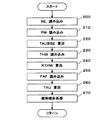
この実施の形態のエンジンシステムでは、上記のように検出される最終的な吸気圧PMを使用して燃料噴射制御が行われる。そこで、次に、この燃料噴射制御の処理内容について説明する。図7に燃料噴射制御のプログラムをフローチャートに示す。ECU20は、このルーチンを所定期間毎に周期的に実行する。
【0051】
先ず、ステップ200で、ECU20は回転速度センサ23の検出値に基づきエンジン回転速度NEの値を読み込む。
【0052】
ステップ210で、ECU20は、最終的な吸気圧PMの値を読み込む。即ち、脈動を伴う吸気圧pmの下限値pmloを最終的な吸気圧PMの値として読み込む。
【0053】
ステップ220で、ECU20は、読み込まれたエンジン回転速度NEの値と吸気圧PMの値とに基づいて基本燃料噴射量TAUBSEを算出する。ECU20は、この基本燃料噴射量TAUBSEの算出を、予め定められた関数データ(噴射量マップ)を参照することにより行う。この関数データでは、エンジン3の燃焼室8に吸入される吸気量が、吸気圧PMの値とエンジン回転速度NEの値から決定され、その吸気量に応じた基本燃料噴射量TAUBSEが決定されるようになっている。
【0054】
ステップ230で、ECU20は、水温センサ22の検出値に基づき冷却水温THWの値を読み込む。そして、ステップ240で、ECU20は、読み込まれた冷却水温THWの値に基づき、エンジン3の暖機状態に応じて基本燃料噴射量TAUBSEを補正するための暖機補正係数KTHWを算出する。
【0055】
ステップ250で、ECU20は、燃焼室8に供給される空気と燃料との可燃混合気の空燃比A/Fを補正するための空燃比補正係数FAFの値を読み込む。この空燃比補正係数FAFは、酸素センサ24の検出値から読み込まれる酸素濃度Oxの値に基づいて算出されるものである。
【0056】
ステップ260で、ECU20は、上記のように算出された基本燃料噴射量TAUBSEを、暖機補正係数KTHW及び空燃比補正係数FAF等に基づいて補正することにより最終燃料噴射量TAUの値を算出する。
【0057】
その後、ステップ270で、ECU20は、算出された最終燃料噴射量TAUの値に基づいてインジェクタ4を制御することにより、インジェクタ4から噴射される燃料量を制御するのである。
【0058】
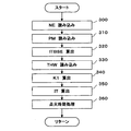
この実施の形態のエンジンシステムでは、上記のように検出される最終的な吸気圧PMを使用して点火時期制御が行われる。そこで、この点火時期制御の処理内容について説明する。図8に点火時期制御のプログラムをフローチャートに示す。ECU20は、このルーチンを所定期間毎に周期的に実行する。
【0059】
先ず、ステップ300で、ECU20は回転速度センサ23の検出値に基づきエンジン回転速度NEの値を読み込む。
【0060】
ステップ310で、ECU20は、最終的な吸気圧PMの値を読み込む。即ち、脈動を伴う吸気圧pmの下限値pmloを最終的な吸気圧PMの値として読み込む。
【0061】
ステップ320で、ECU20は、読み込まれたエンジン回転速度NEの値と吸気圧PMの値とに基づいて基本点火時期ITBSEを算出する。ECU20は、この基本点火時期ITBSEの算出を、予め定められた関数データ(点火時期マップ)を参照することにより行う。この関数データでは、エンジン3の燃焼室8に吸入される吸気量が、吸気圧PMの値とエンジン回転速度NEの値から決定され、その吸気量に応じた基本点火時期ITBSEが決定されるようになっている。
【0062】
ステップ330で、ECU20は、水温センサ22の検出値に基づき冷却水温THWの値を読み込む。そして、ステップ340で、ECU20は、読み込まれた冷却水温THWの値に基づき、エンジン3の暖機状態に応じて基本点火時期ITBSEを補正するための暖機補正係数K1を算出する。
【0063】
ステップ350で、ECU20は、上記のように算出された基本点火時期ITBSEを、暖機補正係数K1等に基づき補正することにより、最終点火時期ITの値を算出する。
【0064】
その後、ステップ360で、ECU20は、算出された最終点火時期ITの値に基づいてイグニションコイル13を制御することにより、点火プラグ12による点火時期を制御する。
【0065】
以上説明した本実施の形態のエンジンシステムにおいて、エンジン3の運転時には吸気通路6で吸気の脈動が発生して、吸気圧センサ21で検出される吸気圧pmは脈動を伴ったものとなる。このため、脈動を伴った吸気圧pmを、エンジン3の各種制御を実行するための運転パラメータの一つとしてそのまま使用したのでは、各種制御が不安定となる。
【0066】
ここで、本願出願人は、脈動を伴う吸気圧pmの検出値において、その下限値pmloが、実際に燃焼室8に吸入される吸気量を最も良く反映した吸気圧となることを発見した。そこで、このエンジンシステムが実行する吸気圧検出方法では、吸気圧脈動、即ち、脈動を伴う吸気圧pmについてその下限値pmloを算出し、その下限値pmloを最終的な吸気圧PMとして決定するようにしている。このことから、脈動を伴う吸気圧pmにも拘わらず、最終的な吸気圧PMとして吸気量に相関した適正な値と挙動が得られる。これによって、安定性と応答性に優れ、実際の吸気量との相関性の高い最終的な吸気圧PMを検出することができるようになる。
【0067】
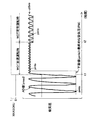
図9(a),(b)には、アクセル開度の変化に対する吸気圧の挙動をタイムチャートに示す。図9(b)において、破線は吸気圧pmのAD値pmadを示し、実線は本実施の形態の検出により得られる最終的な吸気圧PMを示し、2点鎖線は従来のなまし処理によるなまし吸気圧を示す。
【0068】
このチャートからも明らかなように、加速開始前と加速終了後では、変化のないアクセル開度の挙動に合わせて吸気圧PMも安定することが分かる。又、加速開始から加速終了までの間の過渡運転時では、吸気圧PMも段階的に速やかに上昇することが分かる。これを、2点鎖線で示す従来のなまし吸気圧の挙動と比較すると、本実施の形態の吸気圧PMは、加速終了後の時刻t1に安定するのに対し、従来のなまし吸気圧は、かなり遅れた時刻t2に安定することになる。従って、本実施の形態の吸気圧検出方法によれば、両時刻t1,t2の間の時間だけ応答性を改善した吸気圧PMを検出できることが分かる。
【0069】
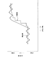
図10に、エンジン負荷に対する吸気圧の算出特性をグラフに示す。このグラフから明らかなように、従来のなまし吸気圧は、エンジン負荷の増加に対して曲線的に増加するのに対し、本実施の形態の吸気圧PMでは、直線的に増加することが分かる。即ち、本実施の形態の吸気圧PMの方がエンジン負荷に対してリニアリティがあることが分かる。このことは、アクセル装置によるスロットルバルブ9の動きに対して吸気圧PMがリニアに反応することを意味し、過渡時に検出される吸気圧PMの応答性が向上していることを示している。これによって、吸気圧PMから換算される吸気量が、従来のなまし吸気圧により換算される吸気量に対して、より正確なものになることが分かる。
【0070】
ところで、この実施の形態のエンジン3では、運転中に吹き返しなどが発生すると、吸気通路6での吸気圧脈動の波形が乱れ、その乱れによる変則的な下限値が吸気圧脈動の正規の下限値に混じって現れることがある。
【0071】
これに対して、この実施の形態では、脈動を伴う吸気圧pmのAD値pmadの下限値を算出すると共に、エンジン回転速度NEに応じたしきい値pthreを算出している。そして、計算上は下限値となるAD値pmadが、しきい値pthreより小さくなるとき、その下限値となるAD値pmadを吸気圧pmの検出値である最終的な吸気圧PMとして決定するようにしている。従って、例えば、エンジン3の吹き返しなどにより、脈動を伴う吸気圧pmの波形が乱れて変則的な下限値が現れても、その変則的な下限値が正規の下限値から除外されるので、変則的な下限値が最終的な吸気圧PMの値として決定されることがない。このため、エンジン3の吹き返しなどにより脈動を伴う吸気圧pmが乱れても、最終的な吸気圧PMの誤検出を防止することができる。
【0072】
しかも、この実施の形態では、上記しきい値pthreが、下限値pmloと共に算出される上限値pmhiを基準に、その上限値pmhiより所定の設定幅pmwだけ小さい値として算出される。ここで、所定の設定幅pmwは、エンジン3の高負荷定常運転時における吸気圧脈動のエンジン回転速度NEの違いに応じた振幅に基づいて予め設定されたものであることから、しきい値pthreとしては、エンジン回転速度NEにより変わる下限値pmloとの比較に好適な値が得られる。このため、吹き返しなどによる吸気圧pmの乱れの程度がエンジン回転速度NEの違いにより変わっても、変則的な下限値が正規の下限値から適正に除外されるので、最終的な吸気圧PMの誤検出を適正に防止することができる。
【0073】
ここで、エンジン3の過渡運転時、即ち、減速運転時及び加速運転時には、吸気圧脈動の振幅が定常運転時のそれに比べて小さくなり、その吸気圧脈動の下限値pmloも相対的に大きくなることから、その下限値pmloがしきい値pthreよりも大きくなる傾向がある。例えば、エンジン3の急加速時には、図11に示すように、時刻t1〜t2においてスロットルバルブ9の急開後しばらくの間は、吸気圧pmのAD値pmadの脈動波形の振幅が、時刻t2以降に続く定常運転時(高負荷)における脈動波形のそれより小さくなり、そのAD値pmadの下限値pmloがしきい値pthreより大きくなる。そのため、エンジン3の加速直後である時刻t1〜t2の間は、エンジン3に対する吸入空気量が増加しているにも拘わらず、検出される最終的な吸気圧PMが小さい値のままとなる。その結果、吸気圧PM等に基づいて算出される最終的な燃料噴射量TAUが少なくなり、空燃比がリーン化してエンジン回転速度NEが上昇せず、息つき発生などのドライバビリティの悪化を招くおそれがあった。
【0074】
そこで、この実施の形態では、エンジン3の過渡運転時には、エンジン回転速度NEに応じて算出されるしきい値pthreとは異なり、計算上はそれより大きい別のしきい値pthreが下限値pmloとの比較に参照されるようになっている。即ち、エンジン回転速度NEに応じて算出される設定幅pmwに代わって、減速時用又は加速時用に予め設定され、設定幅pmwより小さい所定値K1,K2と、上限値pmhiとから算出される別のしきい値pthreが、下限値pmloとの比較に参照される。そして、この別のしきい値pthreより下限値pmloが小さくなるとき、その下限値pmloが最終的な吸気圧PMとして決定されるので、過渡運転時に応じて最終的な吸気圧PMの検出を行うことが可能となる。このため、過渡運転時における最終的な吸気圧PMの誤検出を確実に防止することができるようになる。
即ち、エンジン3の急加速時には、図12に示すように、しきい値pthreが、図11に示すしきい値pthreより大きくなり、時刻t1〜t2におけるAD値pmadの下限値pmloが、そのしきい値pthreより大きくなることがない。このため、急加速直後に急増するAD値pmadの下限値pmloを適正にとらえることができる。この結果、エンジン3の加速直後である時刻t1〜t2においても、エンジン3に対する吸入空気量の増加に応じて増える最終的な吸気圧PMを適正に検出することができる。つまり、エンジン3の過渡運転に応じて吸気圧の適正な検出を行うことができる。
そして、この実施の形態では、適正に検出された最終的な吸気圧PMを、燃料噴射量制御と点火時期制御に取り込んでいることから、適正な吸気量を算出することができ、過渡運転時に見合った適正な燃料噴射制御と適正な点火時期制御を実行することができる。この結果、応答性に優れた過渡運転をエンジン3で実現することができる。又、例えば、急加速時に応答遅れがあって、吸入空気量に対して最終燃料噴射量TAUが少なくなり空燃比A/Fがリーン化するのとは異なり、この実施の形態では、急加速時に、吸入空気量に対して適正な最終燃料噴射量TAUが得られ、空燃比A/Fが適正化するので、エンジン回転速度NEを順調に高めることができ、適正なドライバビリティを確保することができる。
【0075】
この実施の形態のエンジンシステムによれば、エンジン3の運転時に、吸気圧センサ21により検出される吸気圧pmのAD値pmadから、吸気圧脈動の下限値pmloがECU20により算出される。同じく、運転時に、回転速度センサ23により検出されるエンジン回転速度NEの値に応じたしきい値pthreがECU20により算出される。更に、しきい値pthreより下限値pmloが小さくなるとき、その下限値pmloがECU20により吸気圧pmの検出値としての最終的な吸気圧PMとして決定される。この決定された最終的な吸気圧PMの値とエンジン回転速度NEの検出値等とに基づいて、最終燃料噴射量TAU及び最終点火時期ITがECU20により操作量としてそれぞれ算出される。そして、それら操作量TAU,ITに基づいてインジェクタ4及びイグニションコイル13等がECU20によりそれぞれ制御されることにより、燃料噴射制御及び点火時期制御が実行される。
従って、脈動を伴う吸気圧pmのAD値pmadの中から、エンジン3の吹き返しなどに起因するAD値pmadの乱れによる変則的な下限値が除外され、適正な下限値pmloのみが最終的な吸気圧PMの値としてインジェクタ4及びイグニションコイル13等の制御に取り込まれる。このことから、吸気圧pmが脈動を伴い、その脈動に乱れが生じることがあるにも拘わらず、操作量としての最終燃料噴射量TAU及び最終点火時期ITの値が適正に求められ、インジェクタ4及びイグニションコイル13等が吸気圧pmの挙動に応じて適正に制御されるようになる。この結果、安定性と応答性に優れた燃料噴射制御及び点火時期制御を実行することができ、実際の吸気量との相関性が高く、吸気圧脈動の乱れの影響の少ない正確な燃料噴射制御及び点火時期制御を実行することができる。併せて、エンジン3の吹き返しなどに影響を受けることのない安定した制御を実行することができる。
【0076】
尚、この発明は前記実施の形態に限定されるものではなく、発明の趣旨を逸脱することのない範囲で以下のように実施することもできる。
【0077】
(1)前記実施の形態では、本発明の吸気圧検出方法、吸気圧検出装置、内燃機関の制御装置等を単気筒のエンジン3を含むエンジンシステムに具体化したが、2気筒や3気筒、或いはそれ以上の気筒数のエンジンを含むエンジンシステムに具体化することもできる。但し、気筒数が多ければ吸気脈動の振幅も小さくなることから、本発明の効果は1〜3の気筒数のエンジンで特に有効と言える。
【0078】
(2)前記実施の形態では、本発明を燃料噴射制御及び点火時期制御に具体化したが、それらの制御に限られるものではなく、吸気圧を運転パラメータの一つとして使用する排気還流制御等のその他の制御に使用してもよい。
【0079】
【発明の効果】
請求項1に記載の発明の構成によれば、安定性と応答性に優れ、実際の吸気量との相関性の高い吸気圧の検出を行うことができると共に、内燃機関の吹き返しなどによる吸気圧の誤検出を防止することができる。
【0080】
請求項2に記載の発明の構成によれば、請求項1に記載の発明の効果に加え、内燃機関の吹き返しなどによる吸気圧の乱れの程度が回転速度の違いにより変わっても、吸気圧の誤検出を適正に防止することができる。
【0081】
請求項3に記載の発明の構成によれば、請求項1に記載の発明の効果に加え、内燃機関の過渡運転に応じて吸気圧の適正な検出を行うことができる。
【0082】
請求項4に記載の発明の構成によれば、安定性と応答性に優れ、実際の吸気量との相関性の高い吸気圧の検出を行うことができると共に、エンジン吹き返しなどによる吸気圧の誤検出を防止することができる。
【0083】
請求項5に記載の発明の構成によれば、請求項4に記載の発明の効果に加え、内燃機関の過渡運転に応じて吸気圧の適正な検出を行うことができる。
【0084】
請求項6に記載の発明の構成によれば、安定性と応答性に優れ、実際の吸気量との相関性の高い正確な内燃機関制御を実行することができ、併せて、内燃機関の吹き返しなどに影響を受けることのない安定した制御を実行することができる。
【図面の簡単な説明】
【図1】 一実施の形態に係り、エンジンシステムを示す概略構成図である。
【図2】 吸気圧検出制御のプログラムを示すフローチャートである。
【図3】 エンジン回転速度に対する設定幅の関係を示すデータマップである。
【図4】 (a)〜(c)は、吸気圧脈動波形の違いを示すグラフである。
【図5】 脈動を伴う吸気圧のAD値等を示す説明図である。
【図6】 脈動を伴う吸気圧のAD値等を示す説明図である。
【図7】 燃料噴射制御のプログラムを示すフローチャートである。
【図8】 点火時期制御のプログラムを示すフローチャートである。
【図9】 (a),(b)はアクセル開度の変化に対する吸気圧の挙動を示すタイムチャートである。
【図10】 エンジン負荷に対する吸気圧の算出特性を示すグラフである。
【図11】 加速運転時における吸気圧のAD値等の挙動を示すタイムチャートである。
【図12】 加速運転時における吸気圧のAD値等の挙動を示すタイムチャートである。
【図13】 従来の吸気圧の検出値と計算値の挙動を示すタイムチャートである。
【図14】 従来の吸気圧検出方法を示すタイムチャートである。
【符号の説明】
3 エンジン(内燃機関)
4 インジェクタ(燃料噴射弁、制御対象)
6 吸気通路
12 点火プラグ(制御対象)
13 イグニションコイル(制御対象)
20 ECU(下限値算出手段、しきい値算出手段、吸気圧決定手段、過渡運転
判断手段、別のしきい値算出手段、操作量算出手段及び制御手段)
21 吸気圧センサ(吸気圧検出手段)
23 回転速度センサ(回転速度検出手段)[0001]
BACKGROUND OF THE INVENTION
The present invention relates to an intake pressure detection method for detecting an intake pressure used as an operation parameter necessary for control of an internal combustion engine, an intake pressure detection device used directly for carrying out the intake pressure detection method, and control of the internal combustion engine. Relates to the device.
[0002]
[Prior art]
Conventionally, the intake pressure of an internal combustion engine has been used as one of operating parameters for control of various internal combustion engines such as fuel injection control, ignition timing control or exhaust gas recirculation control. For example, in an engine of a so-called “DJ system” (a system that performs fuel injection by measuring the intake pressure in the intake passage), the amount of intake air taken into the combustion chamber of the engine is calculated from the intake pressure and the engine speed. The fuel injection amount is obtained based on the calculated intake air amount. However, in the reciprocating engine, pulsation is generated in the intake air with the reciprocating motion of the piston, so that the intake pressure also fluctuates accordingly. For this reason, it is impossible to use the value of the intake pressure detected by the intake pressure sensor as an operating parameter as it is because the control of the internal combustion engine becomes unstable.
[0003]
Therefore, various techniques have been proposed so far in order to detect the intake pressure excluding the influence of the intake pulsation and use it for the control of the internal combustion engine.
[0004]
As a general technique, it is conceivable to smooth the fluctuation of the intake pressure accompanying the pulsation of the intake air by “smoothing” the detection value by the intake pressure sensor. “Annealing process” is an averaging process of detection values sampled at a predetermined cycle, and the degree of averaging can be arbitrarily set as an “annealing coefficient”.
[0005]
In addition, an example of a similar technique is disclosed in Japanese Patent Laid-Open No. 1-318938. That is, in the intake pipe pressure measuring device of this publication, the intake pressure detected by the intake pressure sensor is sampled every predetermined drive cycle, and the detected value of the intake pressure obtained by the sampling is arithmetically averaged to obtain an average value. Is calculated. Then, during the transient operation of the internal combustion engine, this average value is directly used as the calculated value of the intake pressure for controlling the fuel injection amount. On the other hand, during steady-state operation of the internal combustion engine, the average value obtained by the above arithmetic averaging process is further averaged, and the average value obtained by the averaging is used as the calculated value of the intake pressure as it is for controlling the fuel injection amount. Like to do. That is, in this measuring device, the calculated value obtained by “smoothing once” the detected value of the intake pressure sensor during transient operation is used as the intake pressure, and the detected value of the intake pressure sensor is set to “2” during steady operation. The calculated value obtained by performing the "smoothing process" is used as the intake pressure for the fuel injection amount control.
[0006]
[Problems to be solved by the invention]
However, in the conventional measurement method using the general “smoothing process”, when the smoothing coefficient is increased, the calculated value of the intake pressure is stable during steady operation but tends to cause a response delay during transient operation. On the other hand, when the smoothing coefficient is reduced, the calculated value of the intake pressure tends to become unstable during steady operation, although the response delay during transient operation is improved.
[0007]
On the other hand, as shown in FIG. 13, in the measuring device of the above-mentioned conventional publication, the calculated value of the intake pressure is stable during steady operation, and the responsiveness during transient operation is also improved compared to the general better processing. become. However, as the accuracy of the calculated value, the correlation with the intake air amount actually taken into the combustion chamber is not sufficient, and the characteristic with linearity was not obtained in the relationship of the calculated intake pressure to the load of the internal combustion engine.
[0008]
Here, the applicant of the present invention is a four-cycle reciprocating engine, and in the fluctuation of the intake pressure accompanying the pulsation of intake air, the lower limit value of the intake pressure, that is, the detected value near the bottom dead center of the intake stroke, It was discovered that the intake pressure best reflects the intake air amount, and the idea of using this as the calculated value of the intake pressure has been devised, and has already been proposed in the application of Japanese Patent Application No. 2000-293439. That is, during operation of the internal combustion engine, as shown in FIG. 14, the lower limit value pmlo of the AD value pmad of the intake pressure that changes with pulsation is calculated, and the lower limit value pmlo is finally used as the detected value of the intake pressure. A method for detecting the intake pressure of an internal combustion engine using the intake pressure PM is proposed.
[0009]
As a result of further examination by the applicant of this proposed technique, when the engine is running, a blowback or the like occurs, and the waveform of the AD value pmad is disturbed as indicated by times t1 and t2 in FIG. It has been found that the irregular lower limit due to turbulence may be erroneously detected as the lower limit pmlo of the intake pressure pulsation. When such a false detection occurs, the intake air amount of the engine is calculated as a value larger than the actual value, and the fuel injection amount is excessively calculated accordingly. There is a risk of causing problems such as worsening exhaust emissions.
[0010]
Therefore, the present invention has been made in view of the above circumstances, and its purpose is to enable detection of an intake pressure which is excellent in stability and responsiveness and has a high correlation with an actual intake amount, and an engine. An object of the present invention is to provide an intake pressure detection method for an internal combustion engine that can prevent erroneous detection due to blowback or the like.
[0011]
[Means for Solving the Problems]
In order to achieve the above object, an intake pressure detection method for an internal combustion engine according to
[0012]
During operation of the internal combustion engine, pulsation occurs in the intake air, and the intake pressure also pulsates. Therefore, if this intake pressure is used as it is for the control of the internal combustion engine, the control becomes unstable. Here, it has already been discovered that the lower limit value of the detected value of the intake pressure pulsation is the intake pressure that best reflects the actual intake amount.
Therefore, according to the configuration of the above invention, the lower limit value of the intake pressure pulsation is calculated, Calculated Lower limit is Used for control Of intake pressure Ultimate Since it is determined as the detection value, an appropriate value and behavior correlated with the intake air amount can be obtained as the intake air pressure regardless of the intake air pressure with pulsation.
When the lower limit value is smaller than the threshold value calculated according to the rotational speed of the internal combustion engine, the lower limit value is Used for control Of intake pressure Ultimate Since it is determined as the detected value, for example, even if the waveform of the intake pressure pulsation is disturbed due to the blowback of the internal combustion engine and the like, an irregular lower limit value appears, the irregular lower limit value is excluded and the intake pressure Ultimate It is not determined as a detection value.
[0013]
In order to achieve the above object, according to a second aspect of the present invention, in the intake pressure detection method for an internal combustion engine according to the first aspect of the present invention, the threshold value is an upper limit of the intake pressure pulsation calculated together with the lower limit value. This value is calculated by subtracting a predetermined setting range from the value, and the setting range is set in advance based on the amplitude of the intake pressure pulsation corresponding to the rotational speed at the time of high load steady operation of the internal combustion engine. The purpose is to be.
[0014]
According to the configuration of the above invention, in addition to the operation of the invention described in
[0015]
In order to achieve the above object, the invention described in
[0016]
During the transient operation of the internal combustion engine, the amplitude of the intake pressure pulsation is smaller than that during steady operation, and the lower limit value thereof is relatively large, so that the lower limit value tends to be larger than the threshold value. Therefore, according to the configuration of the above invention, in addition to the operation of the invention described in
[0017]
In order to achieve the above object, an intake pressure detection device for an internal combustion engine according to claim 4 is provided. An intake pressure detection device for an internal combustion engine configured to detect intake pressure used for control of the internal combustion engine, Intake pressure detection means for detecting the intake pressure of the internal combustion engine, and during operation of the internal combustion engine Detected by intake pressure detection means Intake pressure pulsation In the detected value Lower limit value calculating means for calculating the lower limit value, rotational speed detecting means for detecting the rotational speed of the internal combustion engine, and threshold value calculating means for calculating a threshold value corresponding to the detected rotational speed And when the lower limit value is smaller than the threshold value, Used for control Of intake pressure Ultimate It is intended that an intake pressure determining means for determining as a detection value is provided.
[0018]
According to the configuration of the above invention, the intake pressure pulsation is detected by the lower limit value calculating means based on the detected value by the intake pressure detecting means during operation of the internal combustion engine. In the detected value A lower limit value is calculated, and a threshold value according to the rotation speed detected by the rotation speed detection means is calculated by the threshold value calculation means. When the lower limit value becomes smaller than the threshold value, the lower limit value is reduced to the intake pressure by the intake pressure determining means. Ultimate Since it is determined as the detected value, an appropriate value and behavior correlating with the intake air amount can be obtained as the intake air pressure regardless of the intake air pressure accompanying pulsation. In addition, even if the waveform of the intake pressure pulsation is disturbed due to the blowback of the internal combustion engine and an irregular lower limit appears, the irregular lower limit is excluded and the intake pressure Ultimate Can be determined as the detection value Na Yes.
[0019]
In order to achieve the above object, according to a fifth aspect of the present invention, in the intake pressure detecting device for an internal combustion engine according to the fourth aspect of the present invention, a transient operation determining means for determining a transient operation of the internal combustion engine; Another threshold value calculation means for calculating another threshold value that is a threshold value corresponding to the transient operation of the internal combustion engine and is larger than the threshold value, and the intake pressure determination means is a transient value of the internal combustion engine When it is determined that the vehicle is driving, another threshold value calculated by another threshold value calculation unit is selected instead of the threshold value calculated by the threshold value calculation unit, and When the lower limit value decreases, the lower limit value Ultimate The purpose is to determine the detection value.
[0020]
During transient operation of the internal combustion engine, the amplitude of the intake pressure pulsation is smaller than that during steady operation, and the lower limit value thereof is relatively large, and therefore the lower limit value tends to be larger than the threshold value. Therefore, according to the configuration of the above invention, in addition to the operation of the invention according to claim 4, during transient operation of the internal combustion engine, this is determined by the transient operation time determination means, and is calculated by another threshold value calculation means. Another threshold value greater than the threshold value calculated by the threshold value calculation means is referred to the comparison with the lower limit value, and when the lower limit value becomes smaller than the other threshold value, the lower limit value is Ultimate Since the detected value is determined by the intake pressure determining means, it is possible to detect the intake pressure corresponding to the transient operation.
[0021]
In order to achieve the above object, an invention according to a sixth aspect of the present invention relates to an intake pressure detecting means for detecting an intake pressure of an internal combustion engine in a control device for controlling a control object related to the operation of the internal combustion engine. , Rotational speed detection means for detecting the rotational speed of the internal combustion engine, and during operation of the internal combustion engine Detected by intake pressure detection means Intake pressure pulsation According to detected value Lower limit value calculating means for calculating the lower limit value, threshold value calculating means for calculating a threshold value corresponding to the detected rotational speed, and lower limit value when the lower limit value is smaller than the threshold value Used for control Of intake pressure Ultimate Intake pressure determining means for determining the detected value, and the determined intake pressure Ultimate An operation amount calculation means for calculating an operation amount for obtaining a required control amount based on the detection value and the detection value of the rotation speed, and the control amount is controlled by operating the control object based on the calculated operation amount. It is intended to include control means for performing the above.
[0022]
According to the configuration of the invention, the lower limit value of the intake pressure pulsation is calculated by the lower limit value calculating means from the detected value of the intake pressure detected by the intake pressure detecting means during operation of the internal combustion engine. Similarly, during driving, the threshold value calculation means calculates a threshold value corresponding to the rotation speed detected by the rotation speed detection means. When the lower limit value becomes smaller than the threshold value, the lower limit value Ultimate The detected value is determined by the intake pressure determining means. Here, the determined intake pressure Ultimate Based on the detected value and the detected value of the rotation speed, an operation amount for obtaining a required control amount is calculated by the operation amount calculating means, and the control object is operated by operating the control target based on the operation amount. The amount is controlled.
Therefore, the irregular lower limit value due to the disturbance of the intake pressure pulsation is excluded and not determined as the detected value of the intake pressure, and only the lower limit value of the appropriate intake pressure pulsation is determined as the detected value of the intake pressure. Is taken in. As a result, the control amount does not become an unstable value regardless of the intake pressure with pulsation, and the controlled object is appropriately controlled according to the behavior of the intake pressure.
[0023]
DETAILED DESCRIPTION OF THE INVENTION
DETAILED DESCRIPTION OF THE PREFERRED EMBODIMENTS Embodiments of an internal combustion engine intake pressure detection method, an intake pressure detection device using the detection method, and an internal combustion engine control device using the intake pressure detection device according to the present invention will be described below with reference to the drawings. Will be described in detail.
[0024]
FIG. 1 shows a schematic configuration of the engine system of the present embodiment. An engine system mounted on a vehicle includes a
[0025]
The intake passage 6 is provided with a
[0026]
A
[0027]
The vehicle is provided with an
[0028]
[0029]
In this embodiment, the
[0030]
Here, the intake pressure detection control is control for obtaining a detected value of the intake pressure excluding the influence of the intake pulsation based on the intake pressure pm detected by the
[0031]
As is well known, the
[0032]
Next, processing contents for intake pressure detection control among various controls executed by the
[0033]
First, in
[0034]
Next, in
[0035]
Next, in
[0036]
In
[0037]
On the other hand, if the determination result in
[0038]
Next, in
[0039]
In
[0040]
On the other hand, if the determination result in
[0041]
On the other hand, if the determination result in
[0042]
Then, in
[0043]
Thereafter, in
[0044]
In
[0045]
Thereafter, the process proceeds from
[0046]
Next, in
[0047]
In this way, the
[0048]
In the routine described above, the lower limit value pmlo of the pulsation of the intake pressure pm is calculated during operation of the
[0049]
Here, in the above routine, as shown in FIG. 6, the threshold value pthr is obtained from the upper limit value pmhi and the set width pmw, and when the lower limit value pmlo becomes smaller than the threshold value pthre, the lower limit value pmlo is absorbed. The final intake pressure PM, which is the detected value of the atmospheric pressure pm, is determined. Therefore, even if an irregular lower limit value appears in the AD value pmad, as shown in a circle in FIG. 6, if the irregular lower limit value is larger than the threshold value pthre, the irregular lower limit value is The final intake pressure PM is not determined by being excluded from the setting of the lower limit value pmlo.
[0050]
In the engine system of this embodiment, fuel injection control is performed using the final intake pressure PM detected as described above. Therefore, next, the processing content of this fuel injection control will be described. FIG. 7 is a flowchart showing the fuel injection control program. The
[0051]
First, in
[0052]
In
[0053]
In
[0054]
In
[0055]
In
[0056]
In
[0057]
Thereafter, in
[0058]
In the engine system of this embodiment, ignition timing control is performed using the final intake pressure PM detected as described above. Therefore, the processing content of this ignition timing control will be described. FIG. 8 is a flowchart showing the ignition timing control program. The
[0059]
First, at
[0060]
In
[0061]
In
[0062]
In
[0063]
In
[0064]
Thereafter, in
[0065]
In the engine system of the present embodiment described above, intake air pulsation occurs in the intake passage 6 during operation of the
[0066]
Here, the applicant of the present application has found that, in the detected value of the intake pressure pm accompanying pulsation, the lower limit value pmlo is the intake pressure that best reflects the intake amount actually sucked into the
[0067]
9A and 9B are time charts showing the behavior of the intake pressure with respect to changes in the accelerator opening. In FIG. 9B, the broken line indicates the AD value pmad of the intake pressure pm, the solid line indicates the final intake pressure PM obtained by the detection of the present embodiment, and the two-dot chain line is obtained by the conventional annealing process. Better indicates the intake pressure.
[0068]
As is apparent from this chart, it can be seen that the intake pressure PM is also stabilized in accordance with the behavior of the accelerator opening without change before and after the start of acceleration. In addition, it can be seen that the intake pressure PM also rises quickly in steps during the transient operation from the start of acceleration to the end of acceleration. Comparing this with the behavior of the conventional smoothed intake pressure indicated by the two-dot chain line, the intake pressure PM of the present embodiment is stabilized at time t1 after the end of acceleration, whereas the conventional smoothed intake pressure is It becomes stable at time t2 which is considerably delayed. Therefore, according to the intake pressure detection method of the present embodiment, it can be seen that the intake pressure PM with improved responsiveness can be detected for the time between both times t1 and t2.
[0069]
FIG. 10 is a graph showing the calculation characteristic of the intake pressure with respect to the engine load. As is apparent from this graph, the conventional smoothed intake pressure increases in a curve with an increase in engine load, whereas the intake pressure PM in the present embodiment increases in a linear fashion. . That is, it can be seen that the intake pressure PM of the present embodiment has linearity with respect to the engine load. This means that the intake pressure PM reacts linearly to the movement of the
[0070]
By the way, in the
[0071]
On the other hand, in this embodiment, the lower limit value of the AD value pmad of the intake pressure pm accompanied by pulsation is calculated, and the threshold value pthre corresponding to the engine speed NE is calculated. When the AD value pmad serving as the lower limit value is smaller than the threshold value pthre, the AD value pmad serving as the lower limit value is determined as the final intake pressure PM that is the detected value of the intake pressure pm. I have to. Therefore, for example, even when the waveform of the intake pressure pm accompanied by pulsation is disturbed due to the blowback of the
[0072]
Moreover, in this embodiment, the threshold value pthre is calculated as a value smaller than the upper limit value pmhi by a predetermined set width pmw with reference to the upper limit value pmhi calculated together with the lower limit value pmlo. Here, since the predetermined setting range pmw is preset based on the amplitude corresponding to the difference in the engine speed NE of the intake pressure pulsation during the high load steady operation of the
[0073]
Here, during transient operation of the
[0074]
Therefore, in this embodiment, during the transient operation of the
That is, during rapid acceleration of the
In this embodiment, since the properly detected final intake pressure PM is taken into the fuel injection amount control and the ignition timing control, an appropriate intake amount can be calculated, and during transient operation Appropriate proper fuel injection control and proper ignition timing control can be executed. As a result, a transient operation with excellent responsiveness can be realized by the
[0075]
According to the engine system of this embodiment, the
Therefore, the irregular lower limit value due to the disturbance of the AD value pmad caused by the blowback of the
[0076]
In addition, this invention is not limited to the said embodiment, In the range which does not deviate from the meaning of invention, it can also implement as follows.
[0077]
(1) In the above embodiment, the intake pressure detection method, the intake pressure detection device, the control device for the internal combustion engine, and the like of the present invention are embodied in an engine system including a single-
[0078]
(2) In the above embodiment, the present invention is embodied in the fuel injection control and the ignition timing control. However, the present invention is not limited to these controls, and the exhaust gas recirculation control using the intake pressure as one of the operation parameters. It may be used for other controls.
[0079]
【The invention's effect】
According to the configuration of the first aspect of the present invention, it is possible to detect the intake pressure which is excellent in stability and responsiveness and has a high correlation with the actual intake amount, and the intake pressure due to the blowback of the internal combustion engine or the like. False detection can be prevented.
[0080]
According to the configuration of the invention described in
[0081]
According to the configuration of the invention described in
[0082]
According to the configuration of the fourth aspect of the invention, it is possible to detect the intake pressure which is excellent in stability and responsiveness and has a high correlation with the actual intake air amount, and the intake pressure error due to engine blowback or the like is detected. Detection can be prevented.
[0083]
According to the configuration of the invention described in
[0084]
According to the configuration of the invention described in claim 6, it is possible to execute an accurate internal combustion engine control that is excellent in stability and responsiveness and highly correlated with the actual intake air amount. It is possible to execute stable control that is not affected by the above.
[Brief description of the drawings]
FIG. 1 is a schematic configuration diagram showing an engine system according to one embodiment.
FIG. 2 is a flowchart showing a program for intake pressure detection control.
FIG. 3 is a data map showing a relationship of a setting range to engine rotation speed.
4A to 4C are graphs showing differences in intake pressure pulsation waveforms. FIG.
FIG. 5 is an explanatory diagram showing an AD value or the like of intake pressure with pulsation.
FIG. 6 is an explanatory diagram showing an AD value or the like of intake pressure with pulsation.
FIG. 7 is a flowchart showing a program for fuel injection control.
FIG. 8 is a flowchart showing an ignition timing control program.
FIGS. 9A and 9B are time charts showing the behavior of intake pressure with respect to changes in accelerator opening. FIGS.
FIG. 10 is a graph showing calculation characteristics of intake pressure with respect to engine load.
FIG. 11 is a time chart showing the behavior of an intake pressure AD value and the like during acceleration operation.
FIG. 12 is a time chart showing the behavior of the intake pressure AD value and the like during acceleration operation.
FIG. 13 is a time chart showing the behavior of a detected value and a calculated value of a conventional intake pressure.
FIG. 14 is a time chart showing a conventional intake pressure detection method.
[Explanation of symbols]
3 Engine (Internal combustion engine)
4 Injector (fuel injection valve, control target)
6 Air intake passage
12 Spark plug (control target)
13 Ignition coil (control target)
20 ECU (lower limit calculation means, threshold value calculation means, intake pressure determination means, transient operation
Determination means, another threshold value calculation means, operation amount calculation means and control means)
21 Intake pressure sensor (intake pressure detection means)
23 Rotational speed sensor (Rotational speed detection means)
Claims (6)
前記内燃機関の運転時に吸気圧脈動を吸気圧検出手段により検出し、その検出値における下限値を算出すると共に、前記内燃機関の回転速度に応じたしきい値を算出し、そのしきい値より前記下限値が小さくなるとき前記下限値を前記制御に使用される吸気圧の最終的な検出値として決定することを特徴とする内燃機関の吸気圧検出方法。 An intake pressure detection method for an internal combustion engine that detects an intake pressure used to control the internal combustion engine,
An intake pressure pulsation is detected by the intake pressure detection means during operation of the internal combustion engine, a lower limit value is calculated in the detected value , and a threshold value corresponding to the rotational speed of the internal combustion engine is calculated, and from the threshold value An intake pressure detection method for an internal combustion engine, wherein when the lower limit value becomes smaller, the lower limit value is determined as a final detected value of an intake pressure used for the control .
前記設定幅は、前記内燃機関の高負荷定常運転時における前記回転速度に応じた吸気圧脈動の振幅に基づき予め設定されたものである
ことを特徴とする請求項1に記載の内燃機関の吸気圧検出方法。The threshold value is calculated by subtracting a predetermined setting range from the upper limit value of the intake pressure pulsation calculated together with the lower limit value,
2. The internal combustion engine intake system according to claim 1, wherein the set width is preset based on an amplitude of an intake pressure pulsation corresponding to the rotation speed during high-load steady operation of the internal combustion engine. Barometric pressure detection method.
前記内燃機関の吸気圧を検出するための吸気圧検出手段と、
前記内燃機関の運転時に前記吸気圧検出手段により検出される吸気圧脈動の検出値における下限値を算出するための下限値算出手段と、
前記内燃機関の回転速度を検出するための回転速度検出手段と、
前記検出される回転速度に応じたしきい値を算出するためのしきい値算出手段と、
前記しきい値より前記下限値が小さくなるとき前記下限値を前記制御に使用される吸気圧の最終的な検出値として決定するための吸気圧決定手段と
を備えたことを特徴とする内燃機関の吸気圧検出装置。 An intake pressure detection device for an internal combustion engine configured to detect intake pressure used for control of the internal combustion engine,
An intake pressure detecting means for detecting the intake pressure of the internal combustion engine,
And the lower limit value calculating means for calculating a lower limit value of the detected value of the intake pressure pulsations detected by the intake pressure detecting means during the operation of the prior SL internal combustion engine,
A rotational speed detecting means for detecting the rotational speed of the internal combustion engine;
Threshold value calculating means for calculating a threshold value according to the detected rotational speed;
And an intake pressure determining means for determining the lower limit value as a final detected value of the intake pressure used for the control when the lower limit value is smaller than the threshold value. Intake pressure detection device.
前記内燃機関の過渡運転に応じたしきい値であって前記しきい値より大きい別のしきい値を算出するための別のしきい値算出手段と
を備え、前記吸気圧決定手段は、前記内燃機関の過渡運転と判断されたときに、前記しきい値算出手段により算出されるしきい値に代わって前記別のしきい値算出手段により算出される別のしきい値を選択し、その別のしきい値より前記下限値が小さくなるとき前記下限値を吸気圧の最終的な検出値として決定することを特徴とする請求項4に記載の内燃機関の吸気圧検出装置。Transient operation determining means for determining transient operation of the internal combustion engine;
Another threshold value calculating means for calculating another threshold value that is a threshold value corresponding to the transient operation of the internal combustion engine and is larger than the threshold value, the intake pressure determining means, When it is determined that the internal combustion engine is in a transient operation, another threshold value calculated by the another threshold value calculation unit is selected instead of the threshold value calculated by the threshold value calculation unit, The intake pressure detecting device for an internal combustion engine according to claim 4, wherein when the lower limit value becomes smaller than another threshold value, the lower limit value is determined as a final detected value of the intake pressure.
前記内燃機関の吸気圧を検出するための吸気圧検出手段と、
前記内燃機関の回転速度を検出するための回転速度検出手段と、
前記内燃機関の運転時に前記吸気圧検出手段により検出される吸気圧脈動の検出値に係る下限値を算出するための下限値算出手段と、
前記検出される回転速度に応じたしきい値を算出するためのしきい値算出手段と、
前記しきい値より前記下限値が小さくなるとき前記下限値を前記制御に使用される吸気圧の最終的な検出値として決定するための吸気圧決定手段と、
前記決定される吸気圧の最終的な検出値と前記回転速度の検出値とに基づいて所要の制御量を得るための操作量を算出する操作量算出手段と、
前記算出される操作量に基づいて前記制御対象を操作することにより前記制御量を制御するための制御手段と
を備えたことを特徴とする内燃機関の制御装置。In a control device that controls a control object related to the operation of the internal combustion engine,
Intake pressure detecting means for detecting the intake pressure of the internal combustion engine;
A rotational speed detecting means for detecting the rotational speed of the internal combustion engine;
And the lower limit value calculating means for calculating a lower limit value of the detection value of the intake pressure pulsations detected by the intake pressure detecting means during the operation of the prior SL internal combustion engine,
Threshold value calculating means for calculating a threshold value according to the detected rotational speed;
Intake pressure determining means for determining the lower limit value as a final detected value of the intake pressure used for the control when the lower limit value is smaller than the threshold value;
An operation amount calculating means for calculating an operation amount for obtaining a required control amount based on the final detected value of the determined intake pressure and the detected value of the rotational speed;
A control device for an internal combustion engine, comprising: control means for controlling the control amount by operating the control object based on the calculated operation amount.
Priority Applications (3)
| Application Number | Priority Date | Filing Date | Title |
|---|---|---|---|
| JP2001296775A JP3973390B2 (en) | 2001-09-27 | 2001-09-27 | Intake pressure detection method for internal combustion engine |
| TW91116804A TW552407B (en) | 2001-09-27 | 2002-07-26 | Intake-air pressure detecting method for internal-combustion engine |
| CN 02132182 CN1260557C (en) | 2001-09-27 | 2002-08-28 | Intake air pressure detection method for internal combustion engine |
Applications Claiming Priority (1)
| Application Number | Priority Date | Filing Date | Title |
|---|---|---|---|
| JP2001296775A JP3973390B2 (en) | 2001-09-27 | 2001-09-27 | Intake pressure detection method for internal combustion engine |
Publications (2)
| Publication Number | Publication Date |
|---|---|
| JP2003097340A JP2003097340A (en) | 2003-04-03 |
| JP3973390B2 true JP3973390B2 (en) | 2007-09-12 |
Family
ID=19117952
Family Applications (1)
| Application Number | Title | Priority Date | Filing Date |
|---|---|---|---|
| JP2001296775A Expired - Fee Related JP3973390B2 (en) | 2001-09-27 | 2001-09-27 | Intake pressure detection method for internal combustion engine |
Country Status (3)
| Country | Link |
|---|---|
| JP (1) | JP3973390B2 (en) |
| CN (1) | CN1260557C (en) |
| TW (1) | TW552407B (en) |
Families Citing this family (7)
| Publication number | Priority date | Publication date | Assignee | Title |
|---|---|---|---|---|
| JP4027902B2 (en) * | 2004-03-24 | 2007-12-26 | 株式会社豊田中央研究所 | Apparatus for estimating mixture ignition timing of internal combustion engine and control apparatus for internal combustion engine |
| JP2005291141A (en) * | 2004-04-02 | 2005-10-20 | Denso Corp | Reference position learning device of adjustable valve device |
| CN103353772A (en) * | 2013-08-05 | 2013-10-16 | 莆田学院 | Indoor security oxygen-rich concentration control system |
| KR101534712B1 (en) * | 2013-12-17 | 2015-07-08 | 현대자동차 주식회사 | Method and system for diagnosing and correcting boost pressure sensor and air flow sensor by signal of combustion pressure sensor |
| JP2015129442A (en) * | 2014-01-06 | 2015-07-16 | ヤマハ発動機株式会社 | Saddle ride vehicle |
| CN104533644A (en) * | 2014-12-20 | 2015-04-22 | 河南机电高等专科学校 | Fuel oil controller |
| JP6862870B2 (en) * | 2017-02-01 | 2021-04-21 | スズキ株式会社 | Internal combustion engine control device |
-
2001
- 2001-09-27 JP JP2001296775A patent/JP3973390B2/en not_active Expired - Fee Related
-
2002
- 2002-07-26 TW TW91116804A patent/TW552407B/en not_active IP Right Cessation
- 2002-08-28 CN CN 02132182 patent/CN1260557C/en not_active Expired - Fee Related
Also Published As
| Publication number | Publication date |
|---|---|
| CN1409096A (en) | 2003-04-09 |
| JP2003097340A (en) | 2003-04-03 |
| CN1260557C (en) | 2006-06-21 |
| TW552407B (en) | 2003-09-11 |
Similar Documents
| Publication | Publication Date | Title |
|---|---|---|
| US20030159434A1 (en) | Emission control apparatus for engine | |
| JPH07259629A (en) | Fuel property detection device for internal combustion engine | |
| US6655357B2 (en) | Abnormality detection apparatus for intake system of internal combustion engine | |
| US7040085B2 (en) | Deterioration detecting device for oxygen concentration sensor | |
| US4958612A (en) | Air-fuel ratio control method for internal combustion engines | |
| JP3973390B2 (en) | Intake pressure detection method for internal combustion engine | |
| JP3819494B2 (en) | Fuel supply control device for internal combustion engine | |
| JP2010163932A (en) | Catalyst degradation diagnostic device for internal combustion engine | |
| JP4033718B2 (en) | Stroke discrimination method and stroke discrimination device for internal combustion engine | |
| JPH11107827A (en) | Catalyst temperature controller for internal combustion engine | |
| JP3973387B2 (en) | Intake pressure detection method for internal combustion engine | |
| JP3654781B2 (en) | Measuring device for intake air amount of internal combustion engine | |
| JPH11101144A (en) | Fuel supply control device for internal combustion engine | |
| US6176080B1 (en) | Oxygen concentration sensor abnormality-detecting system for internal combustion engines | |
| JP2008038847A (en) | Oxygen sensor diagnostic device for internal combustion engine | |
| JP3912981B2 (en) | Method for estimating the atmospheric pressure of an internal combustion engine | |
| JP2000130221A (en) | Fuel injection control device for internal combustion engine | |
| JPS6256338B2 (en) | ||
| JP7713599B2 (en) | Control device for internal combustion engine | |
| JP4064092B2 (en) | Engine air-fuel ratio control device | |
| JP2002317686A (en) | Suction pressure detecting method for internal combustion engine | |
| JP4161390B2 (en) | Air-fuel ratio control device for internal combustion engine | |
| JP2004036393A (en) | Air-fuel ratio control device for in-cylinder injection internal combustion engine | |
| JP4446873B2 (en) | Air-fuel ratio control device for internal combustion engine | |
| JPH08303234A (en) | Catalyst deterioration diagnostic device for internal combustion engine |
Legal Events
| Date | Code | Title | Description |
|---|---|---|---|
| A977 | Report on retrieval |
Free format text: JAPANESE INTERMEDIATE CODE: A971007 Effective date: 20060403 |
|
| A131 | Notification of reasons for refusal |
Free format text: JAPANESE INTERMEDIATE CODE: A131 Effective date: 20061114 |
|
| A521 | Written amendment |
Free format text: JAPANESE INTERMEDIATE CODE: A523 Effective date: 20070111 |
|
| TRDD | Decision of grant or rejection written | ||
| A01 | Written decision to grant a patent or to grant a registration (utility model) |
Free format text: JAPANESE INTERMEDIATE CODE: A01 Effective date: 20070605 |
|
| A61 | First payment of annual fees (during grant procedure) |
Free format text: JAPANESE INTERMEDIATE CODE: A61 Effective date: 20070612 |
|
| R150 | Certificate of patent or registration of utility model |
Free format text: JAPANESE INTERMEDIATE CODE: R150 |
|
| FPAY | Renewal fee payment (event date is renewal date of database) |
Free format text: PAYMENT UNTIL: 20100622 Year of fee payment: 3 |
|
| LAPS | Cancellation because of no payment of annual fees |