JP3972400B2 - Focal plane shutter blade device - Google Patents
Focal plane shutter blade device Download PDFInfo
- Publication number
- JP3972400B2 JP3972400B2 JP08207897A JP8207897A JP3972400B2 JP 3972400 B2 JP3972400 B2 JP 3972400B2 JP 08207897 A JP08207897 A JP 08207897A JP 8207897 A JP8207897 A JP 8207897A JP 3972400 B2 JP3972400 B2 JP 3972400B2
- Authority
- JP
- Japan
- Prior art keywords
- blade
- camera body
- exposure
- curtain
- slit
- Prior art date
- Legal status (The legal status is an assumption and is not a legal conclusion. Google has not performed a legal analysis and makes no representation as to the accuracy of the status listed.)
- Expired - Lifetime
Links
Images


Classifications
-
- G—PHYSICS
- G03—PHOTOGRAPHY; CINEMATOGRAPHY; ANALOGOUS TECHNIQUES USING WAVES OTHER THAN OPTICAL WAVES; ELECTROGRAPHY; HOLOGRAPHY
- G03B—APPARATUS OR ARRANGEMENTS FOR TAKING PHOTOGRAPHS OR FOR PROJECTING OR VIEWING THEM; APPARATUS OR ARRANGEMENTS EMPLOYING ANALOGOUS TECHNIQUES USING WAVES OTHER THAN OPTICAL WAVES; ACCESSORIES THEREFOR
- G03B9/00—Exposure-making shutters; Diaphragms
- G03B9/08—Shutters
- G03B9/10—Blade or disc rotating or pivoting about axis normal to its plane
- G03B9/18—More than two members
Description
【0001】
【発明の属する技術分野】
本発明は、フォーカルプレーンシャッタ羽根に関するものである。
【0002】
【従来の技術】
従来のこの種の装置は、特開平8−313972号公報に開示されている。この特開平8−313972号公報に示されているように、アパーチャを先スリット羽根と先被い羽根によって遮光していた。即ち、従来の技術においては、先幕がアパーチャを被った状態では先スリット羽根と他の被い羽根によってアパーチャを遮光する構造であった。このために、先幕が露光のためアパーチャを開き始めるまでの助走距離が短く、先幕速および後幕速を速くすることが困難であった。ただし、次のような改良を加えることが可能であったが、欠点も残ることとなった。
【0003】
従来の技術においては、先幕の走行速度がまだ十分に速くなる前にアパーチャを開き始めるため、シャッタの秒時精度を安定させ、又はシンクロ同調秒時をより高速にしようとすると、先幕速(先幕がアパーチャを開き始めてから、アパーチャを全開するまでの時間)を高速化しなければならない。従来はこのために先幕を駆動するばね力を強くする方法がとられて来た。しかし、ばね力を強くするとシャッタ自体が大きくなり、強いばね力のためにシャッタの耐久性や信頼性に悪影響を及ぼす。さらにシャッタチャージに必要なエネルギも増加するので、現在のように電池によりモータを回転させその駆動力でシャッタチャージを行なうカメラでは電池の消耗が激しくなり、頻繁に電池を交換しなければならなくなるという欠点が残る。
【0004】
また、ばね力を強くすることなく先幕速および後幕速(後幕がアパーチャを閉じ始めてから、アパーチャを全閉するまでの時間)を速くするために、先幕および後幕の材料に炭素繊維複合材(CFRP)等の特殊材料を使用してシャッタ幕を軽量化しようとすると、このような特殊材料は高価であるためにコストアップになるという欠点が残る。
【0005】
【発明が解決しようとする課題】
オートフォーカス装置を有するカメラでは、カメラ本体のミラーボックス底部にオートフォーカス装置が配置される。先幕および後幕は、ファインダ部分が配置されているカメラ本体上部から、オートフォーカス装置が配置されているカメラ本体底部に向かって露光のために走行する。このようなフォーカルプレーンシャッタにおいては、図7に示すように、ファインダ103aとアパーチャ101の上縁101aとの間に、アパーチャ101から退避したシャッタ羽根102、103、104および105が重畳されて収容される。従って、シャッタ羽根102の助走距離Dfを長くしようとすると、上縁101aとファインダ103aとの距離Dhを長くしなければならず、従ってカメラ本体の高さを増加させなければならず、カメラが大型化するという問題が生ずる。
【0006】
本発明は、上記の問題点に鑑みてなされたもので、カメラ本体の高さを増すことなく、先幕および後幕の助走距離を長くして、先幕速および後幕速を速くすることを目的とする。
【0007】
【課題を解決するための手段】
この目的を達成するために、請求項1に記載の発明は、底部側にオートフォーカス装置が配置されたカメラ本体内に設けられるフォーカルプレーンシャッタ羽根装置であって、
露光動作時に露光スリットを形成するための先スリット形成羽根と該露光スリットを形成しない先被い羽根とによって構成され、露光開始前においてアパーチャを被う先幕と、
前記露光動作時に前記露光スリットを形成するための後スリット形成羽根と該露光スリットを形成しない後被い羽根とによって構成され、露光開始後において前記アパーチャを被う後幕と、を有し、
前記先幕及び後幕は露光のために、前記オートフォーカス装置が配置されているカメラ本体底部から、カメラ本体上部に向かって走行し、
前記先幕が前記アパーチャを被った露光開始前の状態では、前記先スリット形成羽根の少なくとも一部及び前記後スリット形成羽根のスリットエッジは、前記カメラ本体の高さ方向において前記オートフォーカス装置の上面よりカメラ本体底部寄りに存在しており、且つ前記露光開始前の状態では、前記先幕のうちの前記先スリット形成羽根以外の羽根が、前記アパーチャを被うことを特徴とする。
【0008】
請求項2に記載の発明は、請求項1において、前記カメラ本体には、撮影レンズと、該カメラ本体に装填されたフィルムが走行するフィルム通路とが設けられており、
前記露光開始前の状態では、前記先スリット形成羽根は、前記撮影レンズの光軸方向において、前記オートフォーカス装置と前記フィルム通路との間に配置されていることを特徴とする。
【0009】
請求項3に記載の発明は、請求項1又は2において、前記後幕を構成する羽根の枚数が、前記先幕を構成する羽根の枚数よりも少ないことを特徴とする。
【0010】
請求項4に記載の発明は、請求項3において、前記後スリット形成羽根と前記先スリット形成羽根、および前記先被い羽根と前記後被い羽根とが、それぞれ同一形状であることを特徴とする。
【0011】
請求項5に記載の発明は、請求項3又は4において、前記先被い羽根の中の最も移動量の少ない羽根に対応する前記後被い羽根を削減したことを特徴とする。
【0012】
請求項6に記載の発明は、請求項1〜5の何れか一項において、前記後スリット形成羽根のスリットエッジは、
前記光軸方向においては、前記オートフォーカス装置と前記カメラ本体に装填されたフィルムが走行するフィルム通路との間に配置されていることを特徴とする。
【0013】
請求項7に記載の発明は、請求項1〜6の何れか一項において、前記先幕を回転駆動する先駆動アームおよび先従動アームと、
前記先駆動アームの回転中心となる第1回転軸と、
前記先従動アームの回転中心となる第2回転軸と、を更に具備し、
前記アパーチャの前記カメラ本体の高さ方向の中心は、前記第1回転軸と前記第2回転軸との中間に位置することを特徴とする。
【0014】
請求項8に記載の発明は、請求項1〜7の何れか一項において、前記後幕を回転駆動する後駆動アームと、
前記後駆動アームの回転中心となる第3回転軸とを有し、
前記第3回転軸は、カメラ本体の高さ方向における前記アパーチャの下縁の延長線より前記カメラ本体底部側に外れる位置関係になっていることを特徴とする。
【0015】
【発明の実施の形態】
以下、本発明の実施の形態を図面に基づいて説明する。
【0016】
図1は、本発明によるフォーカルプレーンシャッタ羽根装置の一実施例を示す断面図である。
【0017】
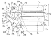
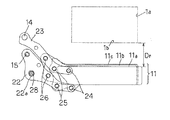
図1において、カメラ本体1にはアパーチャ1aが形成されている。フィルム2、ファインダ3、ペンタプリズム4、スクリーン5、主ミラー6、サブミラー7、撮影レンズ8、オートフォーカス装置9、先幕10、および後幕11は、公知の方法によりカメラ本体1に取り付けられている。撮影前の状態では、図1に示すように、先被い羽根10b、10cおよび10dがアパーチャ1aを被っている。先スリット形成羽根10aは、アパーチャ1aの下方に位置し、アパーチャ1aを被う役目を担っていない。先幕10および後幕11の詳細を図2〜図5に示す。
【0018】
図2〜図5は、図1の矢印A方向から見た先幕10および後幕11の詳細を示す正面図である。図2において、軸12、13、14および15は、不図示のシャッタ基板に設けられている。シャッタ基板は公知の方法によってカメラ本体1に取り付けられている。
【0019】
先駆動アーム16は、軸12の回りに回転可能に取り付けられている。先従動アーム17は、軸13の回りに回転可能に取り付けられている。先スリット形成羽根10aは、ピン18によって先駆動アーム16および先従動アーム17に回転可能に取り付けられている。先被い羽根10b、10cおよび10dは、それぞれピン19、20、および21によって先駆動アーム16および先従動アーム17に回転可能に取り付けられている。先幕は、先スリット形成羽根10a、先被い羽根10b、10cおよび10d、先駆動アーム16、先従動アーム17、ピン18、19、20、および21によって構成されている。
【0020】
後駆動アーム22は、軸15の回りに回転可能に取り付けられている。後従動アーム23は、軸14の回りに回転可能に取り付けられている。後スリット形成羽根11aは、ピン24によって後駆動アーム22および後従動アーム23に回転可能に取り付けられている。後被い羽根11bおよび11cは、ピン25および26によって、それぞれ後駆動アーム22および後従動アーム23に回転可能に取り付けられている(この状態は、図が煩雑となるため図3に分けて示してある)。後幕は、後スリット形成羽根11a、後被い羽根11bおよび11c、後駆動アーム22、後従動アーム23、ピン24、25、および26によって構成されている。
【0021】
後幕の助走距離と先幕の助走距離とが同程度となるように、後スリット形成羽根のスリットエッジ11aは、オートフォーカス装置9の上面(図1のD面)よりカメラ本体底部よりに存在するように配置してある。また、図2に示すように、アパーチャ1aのカメラ本体の高さ方向(B方向)の中心(図2の鎖線Eで示す)は、先駆動アーム16を回転自在に軸支する軸12と先従動アーム17を回転自在に軸支する軸13との間に位置する。また、カメラ本体の高さ方向(B方向)におけるアパーチャ1aの下縁1bより、後駆動アーム22を回転自在に軸支する軸15はカメラ本体底部側に外れている位置関係になっている。
【0022】
また、先スリット形成羽根10aは、光軸方向(図1の矢印A方向)においてはオートフォーカス装置9とフィルム通路29との間に配置され、カメラ本体の高さ方向(図1の矢印B方向)においては、先スリット形成羽根10aの少なくとも一部分はオートフォーカス装置9の上面(図1のD面)よりカメラ本体底部寄りに存在している。
【0023】
次に本発明の動作を説明する。図1、図2および図3の状態から、先駆動アーム16に設けられた長孔16aにはめ合わされた軸27を、公知の方法によって軸12の回りに回転駆動することによって、図1および図2のC方向に先羽根10a〜10dが動かされる。これによって露光動作が開始される。先スリット形成羽根10aが助走距離Dfだけ走行すると、アパーチャ1aを開き始める。この後、先羽根10a〜10dは、図4の位置まで走行すると、公知の方法によって停止する。先羽根10a〜10dが走行を開始してから所定時間経過した後に、後駆動アーム22に設けられた長孔22aにはめ合わされた軸28を、公知の方法によって軸15の回りに回転駆動することによって、図1および図2のC方向に後羽根11a〜11cが動かされる。これによって露光終了動作が開始される。後スリット形成羽根11aが助走距離Dr(図3参照)だけ走行すると、アパーチャ1aを閉じ始める。この後、後羽根11a〜11cは、図5の位置まで走行すると公知の方法によって停止する。
【0024】
本実施例に示すように、先スリット形成羽根10aと後スリット形成羽根11a、先被い羽根10bと後被い羽根11b、先被い羽根10cと後被い羽根11cとを、同一形状とした場合には、先被い羽根10dに対応する後被い羽根11dは、図5の二点鎖線で示すようにアパーチャ1aを遮光する役割を果たさないので不要となる。
【0025】
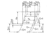
図6は横軸方向に時間を、縦軸方向に先幕および後幕の走行距離をとって、先幕および後幕の走行曲線を描いたものである。図6において、先幕の助走距離をDf1およびDf2で表し、後幕の助走距離をDr1およびDr2で表し、先幕および後幕の走行方向のアパーチャ寸法をApで表してある。また、先幕の助走距離がDf1のときの先幕走行曲線をCf1で表し、後幕の助走距離がDr1のときの後幕走行曲線をCr1で表してある。さらに、先幕の助走距離がDf2のときの先幕走行曲線をCf2で表し、後幕の助走距離かDr2のときの後幕走行曲線をCr2で表している。
【0026】
秒時T(露光時間T)がシンクロ同調秒時とすると、先幕および後幕の助走距離がそれぞれDf2およびDr2の場合には、アパーチャ1aが全開している時間はto2で表される。そしてこの時間to2の間に閃光装置を発光させることになる。一方、先幕および後幕の助走距離が、それぞれDf1およびDr1の場合には、アパーチャ1aが全開している時間はto1となり、時間ts(ts=to1−to2)の余裕が生まれる。この余裕時間tsだけ後幕を早く走行開始させても全開時間to2は確保できるから、このときの秒時Tsをシンクロ同調秒時にできる。明らかにTよりTsの方が短時間であるから、先幕および後幕の助走距離を長くすることによって、シンクロ同調秒時を高速にできる。
【0027】
【発明の効果】
以上のように、本発明のフォーカルプレーンシャッタ羽根装置によれば、カメラ本体内の空きスペースを有効に利用することで、先幕および後幕の助走距離を長くしたので、部品点数を増加させることなく、シャッタ駆動ばねの力を強くすることなく、カメラ本体の高さを増すことなく、先幕速および後幕速を速くすることが可能となる。
【0028】
また、先幕速および後幕速が十分高速になってから、アパーチャ部分を走行させることができるので、最高速秒時(1/8000秒等)においてもスリット幅が広くなり、安定した秒時精度が得られる。またシンクロ同調秒時をより高速にすることが可能となる。
【図面の簡単な説明】
【図1】 本発明によるフォーカルプレーンシャッタ羽根装置の一実施例を示す断面図である。
【図2】 本発明によるフォーカルプレーンシャッタ羽根装置の一実施例を示す正面図である。
【図3】 本発明によるフォーカルプレーンシャッタ羽根装置の一実施例を示す正面図である。
【図4】 本発明によるフォーカルプレーンシャッタ羽根装置の一実施例を示す正面図である。
【図5】 本発明によるフォーカルプレーンシャッタ羽根装置の一実施例を示す正面図である。
【図6】 本発明によるフォーカルプレーンシャッタ羽根装置の一実施例を示す特性図である。
【図7】 従来のフォーカルプレーンシャッタ羽根装置の一例を示す正面図である。
【符号の説明】
1 カメラ本体
1a アパーチャ
2 フィルム
3 ファインダ
4 ペンタプリズム
5 スクリーン
6 主ミラー
7 サブミラー
8 撮影レンズ
9 オートフォーカス装置
10 先幕
10a 先スリット形成羽根
10b 先被い羽根
10c 先被い羽根
10d 先被い羽根
11 後幕
11a 後スリット形成羽根(スリットエッジ)
11b 後被い羽根
11c 後被い羽根
11d 後被い羽根
12 軸
13 軸
14 軸
15 軸
16 先駆動アーム
17 先従動アーム
22 後駆動アーム
23 後従動アーム
27 軸
28 軸[0001]
BACKGROUND OF THE INVENTION
The present invention relates to a focal plane shutter blade.
[0002]
[Prior art]
A conventional device of this type is disclosed in Japanese Patent Application Laid-Open No. 8-313972. As disclosed in Japanese Patent Laid-Open No. 8-313972, the aperture is shielded from light by the leading slit blade and the leading blade. That is, in the prior art, when the front curtain is covered with the aperture, the aperture is shielded by the front slit blade and the other blade. For this reason, the approaching distance until the front curtain starts opening the aperture for exposure is short, and it is difficult to increase the front curtain speed and the rear curtain speed. However, it was possible to make the following improvements, but the drawbacks remained.
[0003]
In the prior art, since the aperture starts to open before the running speed of the front curtain is still sufficiently high, if you try to stabilize the shutter speed accuracy or make the synchro-sync time faster, (Time from the start of the first curtain opening the aperture until the aperture is fully opened) must be increased. Conventionally, a method of increasing the spring force for driving the front curtain has been taken. However, when the spring force is increased, the shutter itself becomes larger, and the durability and reliability of the shutter are adversely affected due to the strong spring force. In addition, since the energy required for shutter charge increases, the camera that rotates the motor with the battery and charges the shutter with the driving force as in the present situation is very exhausted and the battery must be replaced frequently. The fault remains.
[0004]
Further, carbon (from the rear curtain is started closing the aperture, the aperture time to fully closed) leading blade velocity and Komakusoku without strong spring force to quickly, the material of the front and rear curtains If a special material such as a fiber composite material (CFRP) is used to reduce the weight of the shutter curtain, such a special material is expensive and thus has a drawback of increasing the cost.
[0005]
[Problems to be solved by the invention]
In a camera having an autofocus device, the autofocus device is arranged at the bottom of the mirror box of the camera body. The front curtain and the rear curtain travel for exposure from the upper part of the camera body on which the finder portion is disposed toward the bottom of the camera body on which the autofocus device is disposed. In such a focal plane shutter, as shown in FIG. 7,
[0006]
The present invention has been made in view of the above-described problems, and can increase the front curtain speed and the rear curtain speed by increasing the running distance of the front curtain and the rear curtain without increasing the height of the camera body. With the goal.
[0007]
[Means for Solving the Problems]
In order to achieve this object, the invention according to
It is constituted by a front slit forming blade for forming an exposure slit during an exposure operation and a front blade that does not form the exposure slit, and a front curtain that covers the aperture before the start of exposure,
It is constituted by a rear slit forming blade for forming the exposure slit during the exposure operation and a rear cover blade that does not form the exposure slit, and has a rear curtain that covers the aperture after the start of exposure,
For the exposure, the front curtain and the rear curtain travel from the bottom of the camera body where the autofocus device is arranged toward the top of the camera body,
In a state before the start of exposure where the front curtain has covered the aperture, at least a part of the front slit forming blade and the slit edge of the rear slit forming blade are in the height direction of the camera body in the upper surface of the autofocus device. Further, the blades other than the leading slit forming blades of the leading curtain cover the aperture in the state before the exposure start, which is present closer to the bottom of the camera body.
[0008]
The invention described in
In a state before the start of exposure, the leading slit forming blade is disposed between the autofocus device and the film path in the optical axis direction of the photographing lens.
[0009]
According to a third aspect of the present invention, in the first or second aspect, the number of blades constituting the rear curtain is smaller than the number of blades constituting the front curtain.
[0010]
The invention according to claim 4 is characterized in that, in
[0011]
The invention according to
[0012]
The invention according to claim 6 is the slit edge of the rear slit forming blade according to any one of
In the optical axis direction, it is arranged between the autofocus device and a film path along which a film loaded in the camera body travels.
[0013]
A seventh aspect of the present invention provides the first driving arm and the first driven arm for rotating the front curtain according to any one of the first to sixth aspects,
A first rotation shaft serving as a rotation center of the tip drive arm;
A second rotation shaft serving as a rotation center of the first follower arm,
The center of the aperture in the height direction of the camera body is located between the first rotation axis and the second rotation axis.
[0014]
The invention according to claim 8 is the rear drive arm according to any one of
A third rotation shaft serving as a rotation center of the rear drive arm;
The third rotation axis is in a positional relationship that deviates toward the bottom of the camera body from an extension line of the lower edge of the aperture in the height direction of the camera body.
[0015]
DETAILED DESCRIPTION OF THE INVENTION
Hereinafter, embodiments of the present invention will be described with reference to the drawings.
[0016]
FIG. 1 is a sectional view showing an embodiment of a focal plane shutter blade device according to the present invention.
[0017]
In FIG. 1, the
[0018]
2 to 5 are front views showing details of the
[0019]
The
[0020]
The
[0021]
The
[0022]
Further, the leading
[0023]
Next, the operation of the present invention will be described. 1, 2, and 3, the
[0024]
As shown in this embodiment, the leading
[0025]
FIG. 6 shows the travel curves of the front curtain and the rear curtain, with the time in the horizontal axis direction and the travel distance of the front and rear curtains in the vertical axis direction. In FIG. 6, the running distance of the front curtain is represented by Df1 and Df2, the running distance of the rear curtain is represented by Dr1 and Dr2, and the aperture dimension in the running direction of the front curtain and the rear curtain is represented by Ap. Further, the leading curtain traveling curve when the leading curtain traveling distance is Df1 is represented by Cf1, and the trailing curtain traveling curve when the trailing curtain traveling distance is Dr1 is represented by Cr1. Further, the leading curtain traveling curve when the leading curtain traveling distance is Df2 is represented by Cf2, and the trailing curtain traveling curve when the trailing curtain traveling distance is Dr2 is represented by Cr2.
[0026]
Assuming that the second time T (exposure time T) is the synchronization time, the time when the
[0027]
【The invention's effect】
As described above, according to the focal plane shutter blade apparatus of the present invention, the effective distance of the camera body is effectively used to increase the running distance of the front curtain and the rear curtain, thereby increasing the number of parts. In addition, the front curtain speed and the rear curtain speed can be increased without increasing the force of the shutter drive spring and without increasing the height of the camera body.
[0028]
Moreover, since the aperture portion can be driven after the front curtain speed and the rear curtain speed have become sufficiently high, the slit width becomes wide even at the highest speed (such as 1/8000 seconds), and the stable second Accuracy is obtained. It is also possible to make the synchro-sync time faster.
[Brief description of the drawings]
FIG. 1 is a cross-sectional view showing an embodiment of a focal plane shutter blade device according to the present invention.
FIG. 2 is a front view showing an embodiment of a focal plane shutter blade device according to the present invention.
FIG. 3 is a front view showing an embodiment of a focal plane shutter blade device according to the present invention.
FIG. 4 is a front view showing an embodiment of a focal plane shutter blade device according to the present invention.
FIG. 5 is a front view showing an embodiment of a focal plane shutter blade device according to the present invention.
FIG. 6 is a characteristic diagram showing one embodiment of a focal plane shutter blade device according to the present invention.
FIG. 7 is a front view showing an example of a conventional focal plane shutter blade device.
[Explanation of symbols]
DESCRIPTION OF
11b
Claims (8)
露光動作時に露光スリットを形成するための先スリット形成羽根と該露光スリットを形成しない先被い羽根とによって構成され、露光開始前においてアパーチャを被う先幕と、
前記露光動作時に前記露光スリットを形成するための後スリット形成羽根と該露光スリットを形成しない後被い羽根とによって構成され、露光開始後において前記アパーチャを被う後幕と、を有し、
前記先幕及び後幕は露光のために、前記オートフォーカス装置が配置されているカメラ本体底部から、カメラ本体上部に向かって走行し、
前記先幕が前記アパーチャを被った露光開始前の状態では、前記先スリット形成羽根の少なくとも一部及び前記後スリット形成羽根のスリットエッジは、前記カメラ本体の高さ方向において前記オートフォーカス装置の上面よりカメラ本体底部寄りに存在しており、且つ前記露光開始前の状態では、前記先幕のうちの前記先スリット形成羽根以外の羽根が、前記アパーチャを被うことを特徴とするフォーカルプレーンシャッタ羽根装置。 A focal plane shutter blade device provided in a camera body having an autofocus device disposed on the bottom side;
Is constituted by the previously covered blade roots which do not form ahead slit forming blade root and said exposure slit for forming the exposure slit at the time of exposure operation, the front curtain covering the aperture before start of exposure,
It is constituted by a rear slit forming blade for forming the exposure slit during the exposure operation and a rear cover blade that does not form the exposure slit, and has a rear curtain that covers the aperture after the start of exposure ,
For the exposure, the front curtain and the rear curtain travel from the bottom of the camera body where the autofocus device is arranged toward the top of the camera body,
In the state before the start of exposure of the front curtain suffered the aperture, at least a portion and the slit edges of the rear slit forming blade of the destination slit forming blade, the upper surface of the autofocus device in the height direction of said camera body The focal plane shutter blade , which is located closer to the bottom of the camera body and in which the blades other than the front slit forming blade of the front curtain cover the aperture in a state before the start of exposure. apparatus.
前記露光開始前の状態では、前記先スリット形成羽根は、前記撮影レンズの光軸方向において、前記オートフォーカス装置と前記フィルム通路との間に配置されていることを特徴とする請求項1に記載のフォーカルプレーンシャッタ羽根装置。 The camera body is provided with a photographic lens and a film passage through which a film loaded in the camera body travels .
Wherein in the exposure state before the start of the destination slit forming blade, wherein the optical axis direction of the photographing lens, to claim 1, characterized in that it is arranged between the film path and the autofocus device Focal plane shutter blade device.
前記光軸方向においては、前記オートフォーカス装置と前記カメラ本体に装填されたフィルムが走行するフィルム通路との間に配置されていることを特徴とする請求項1〜5の何れか一項に記載のフォーカルプレーンシャッタ羽根装置。The slit edge of the rear slit forming blade is
In the optical axis direction, according to any one of claims 1-5, wherein the autofocus device and loaded in the camera body film is arranged between the film path to travel Focal plane shutter blade device.
前記先駆動アームの回転中心となる第1回転軸と、
前記先従動アームの回転中心となる第2回転軸と、を更に具備し、
前記アパーチャの前記カメラ本体の高さ方向の中心は、前記第1回転軸と前記第2回転軸との中間に位置することを特徴とする請求項1〜6の何れか一項に記載のフォーカルプレーンシャッタ羽根装置。 And the leading driving arm you and destination driven arm for rotating the first curtain,
A first rotary shaft which is a rotational center of the destination drive arm,
Further comprising a second rotating shaft serving as a rotation center of the destination follower arm,
The center of the height Direction of the camera body Apachi catcher is in any one of claims 1 to 6, characterized in that located in the middle between the second rotary shaft and the first rotary shaft The focal plane shutter blade device described .
前記後駆動アームの回転中心となる第3回転軸とを有し、
前記第3回転軸は、カメラ本体の高さ方向における前記アパーチャの下縁の延長線より前記カメラ本体底部側に外れる位置関係になっていることを特徴とする請求項1〜7の何れか一項に記載のフォーカルプレーンシャッタ羽根装置。 A driving arm after rotationally driving the second curtain,
And a third rotation axis which is a rotational center of the rear drive arm,
The third axis of rotation, any one of claims 1 to 7, characterized in that are in a positional relationship of extended line of the lower edge of the aperture in the height direction of the camera body deviates to the camera body bottom The focal plane shutter blade device according to Item .
Priority Applications (2)
| Application Number | Priority Date | Filing Date | Title |
|---|---|---|---|
| JP08207897A JP3972400B2 (en) | 1997-03-14 | 1997-03-14 | Focal plane shutter blade device |
| US09/039,242 US6106165A (en) | 1997-03-14 | 1998-03-16 | Focal plane shutter device having shutter blades positioned with respect to an autofocus device to improve shutter speed |
Applications Claiming Priority (1)
| Application Number | Priority Date | Filing Date | Title |
|---|---|---|---|
| JP08207897A JP3972400B2 (en) | 1997-03-14 | 1997-03-14 | Focal plane shutter blade device |
Publications (2)
| Publication Number | Publication Date |
|---|---|
| JPH10254023A JPH10254023A (en) | 1998-09-25 |
| JP3972400B2 true JP3972400B2 (en) | 2007-09-05 |
Family
ID=13764436
Family Applications (1)
| Application Number | Title | Priority Date | Filing Date |
|---|---|---|---|
| JP08207897A Expired - Lifetime JP3972400B2 (en) | 1997-03-14 | 1997-03-14 | Focal plane shutter blade device |
Country Status (2)
| Country | Link |
|---|---|
| US (1) | US6106165A (en) |
| JP (1) | JP3972400B2 (en) |
Families Citing this family (6)
| Publication number | Priority date | Publication date | Assignee | Title |
|---|---|---|---|---|
| DE10054096A1 (en) * | 2000-10-31 | 2002-05-08 | Harald Gorr | Photo camera and photographic process |
| JP4434504B2 (en) * | 2001-01-31 | 2010-03-17 | キヤノン株式会社 | Shutter device and camera |
| US6776540B2 (en) * | 2002-02-22 | 2004-08-17 | Canon Kabushiki Kaisha | Shutter device |
| US7604422B2 (en) * | 2006-12-11 | 2009-10-20 | Massachusetts Institute Of Technology | Large-aperture focal plane shutter |
| JP2008219523A (en) * | 2007-03-05 | 2008-09-18 | Canon Inc | Imaging apparatus and control method thereof |
| JP5216034B2 (en) * | 2010-02-22 | 2013-06-19 | セイコープレシジョン株式会社 | Focal plane shutter and optical equipment |
Family Cites Families (7)
| Publication number | Priority date | Publication date | Assignee | Title |
|---|---|---|---|---|
| JPS55142323A (en) * | 1979-04-24 | 1980-11-06 | Seiko Koki Kk | Blade device for focal plane shutter |
| JPS60178417A (en) * | 1984-02-27 | 1985-09-12 | Nippon Kogaku Kk <Nikon> | Focus detecting device |
| US4657366A (en) * | 1985-04-30 | 1987-04-14 | Nippon Kogaku K.K. | Shutter device for camera |
| JP2767108B2 (en) * | 1988-06-17 | 1998-06-18 | 旭光学工業株式会社 | Auto focus camera |
| JPH0687946U (en) * | 1993-05-28 | 1994-12-22 | 株式会社精工舎 | Focal plane shutter |
| JPH07319052A (en) * | 1994-05-20 | 1995-12-08 | Nikon Corp | Screen forming device of camera |
| JPH08313972A (en) * | 1995-05-12 | 1996-11-29 | Nikon Corp | Blade device for focal plane shutter |
-
1997
- 1997-03-14 JP JP08207897A patent/JP3972400B2/en not_active Expired - Lifetime
-
1998
- 1998-03-16 US US09/039,242 patent/US6106165A/en not_active Expired - Lifetime
Also Published As
| Publication number | Publication date |
|---|---|
| JPH10254023A (en) | 1998-09-25 |
| US6106165A (en) | 2000-08-22 |
Similar Documents
| Publication | Publication Date | Title |
|---|---|---|
| JP3972400B2 (en) | Focal plane shutter blade device | |
| JP4174142B2 (en) | Camera barrier device | |
| US4508440A (en) | Bellows shielding structure | |
| JPS5952412B2 (en) | Mirror drive device for single-lens reflex cameras | |
| JP4721556B2 (en) | Camera shutter | |
| JPH0524901Y2 (en) | ||
| JP4060671B2 (en) | Focal plane shutter for camera | |
| JP2007102015A (en) | Focal plane shutter for digital camera | |
| JPH0626896Y2 (en) | Blade support device for focal plane shutter | |
| JP3983347B2 (en) | Focal plane shutter device and camera equipped with the same | |
| JPH01293330A (en) | Camera with vertically traveling focal-plane shutter | |
| JPH058410B2 (en) | ||
| JP2765747B2 (en) | camera | |
| JP2002229096A (en) | Shutter device, camera and picture display device | |
| JPS58186728A (en) | Electromagnetic driving focal-plane shutter | |
| US4264177A (en) | Blade mechanism for use in a focal plane shutter | |
| JPS6120585Y2 (en) | ||
| JP3459084B2 (en) | Focal plane shutter with picture frame switching mechanism | |
| JP4904778B2 (en) | camera | |
| JP2965945B2 (en) | Shutter device | |
| JPH08313972A (en) | Blade device for focal plane shutter | |
| JP2009139420A (en) | Shutter device and camera | |
| JPH0453623Y2 (en) | ||
| JPH01205134A (en) | Focal-plane shutter | |
| JPH0557574B2 (en) |
Legal Events
| Date | Code | Title | Description |
|---|---|---|---|
| A621 | Written request for application examination |
Free format text: JAPANESE INTERMEDIATE CODE: A621 Effective date: 20040226 |
|
| A521 | Written amendment |
Free format text: JAPANESE INTERMEDIATE CODE: A523 Effective date: 20040312 |
|
| A977 | Report on retrieval |
Free format text: JAPANESE INTERMEDIATE CODE: A971007 Effective date: 20060915 |
|
| A131 | Notification of reasons for refusal |
Free format text: JAPANESE INTERMEDIATE CODE: A131 Effective date: 20060926 |
|
| A521 | Written amendment |
Free format text: JAPANESE INTERMEDIATE CODE: A523 Effective date: 20061114 |
|
| TRDD | Decision of grant or rejection written | ||
| A01 | Written decision to grant a patent or to grant a registration (utility model) |
Free format text: JAPANESE INTERMEDIATE CODE: A01 Effective date: 20070522 |
|
| A61 | First payment of annual fees (during grant procedure) |
Free format text: JAPANESE INTERMEDIATE CODE: A61 Effective date: 20070604 |
|
| R150 | Certificate of patent or registration of utility model |
Free format text: JAPANESE INTERMEDIATE CODE: R150 |
|
| FPAY | Renewal fee payment (event date is renewal date of database) |
Free format text: PAYMENT UNTIL: 20100622 Year of fee payment: 3 |
|
| FPAY | Renewal fee payment (event date is renewal date of database) |
Free format text: PAYMENT UNTIL: 20100622 Year of fee payment: 3 |
|
| FPAY | Renewal fee payment (event date is renewal date of database) |
Free format text: PAYMENT UNTIL: 20130622 Year of fee payment: 6 |
|
| S531 | Written request for registration of change of domicile |
Free format text: JAPANESE INTERMEDIATE CODE: R313531 |
|
| FPAY | Renewal fee payment (event date is renewal date of database) |
Free format text: PAYMENT UNTIL: 20130622 Year of fee payment: 6 |
|
| R350 | Written notification of registration of transfer |
Free format text: JAPANESE INTERMEDIATE CODE: R350 |
|
| FPAY | Renewal fee payment (event date is renewal date of database) |
Free format text: PAYMENT UNTIL: 20130622 Year of fee payment: 6 |
|
| R250 | Receipt of annual fees |
Free format text: JAPANESE INTERMEDIATE CODE: R250 |
|
| R250 | Receipt of annual fees |
Free format text: JAPANESE INTERMEDIATE CODE: R250 |
|
| R250 | Receipt of annual fees |
Free format text: JAPANESE INTERMEDIATE CODE: R250 |
|
| R250 | Receipt of annual fees |
Free format text: JAPANESE INTERMEDIATE CODE: R250 |
|
| EXPY | Cancellation because of completion of term |