JP3972041B2 - Dental clinical / technical work tools and dental clinical / technical methods - Google Patents
Dental clinical / technical work tools and dental clinical / technical methods Download PDFInfo
- Publication number
- JP3972041B2 JP3972041B2 JP2004226576A JP2004226576A JP3972041B2 JP 3972041 B2 JP3972041 B2 JP 3972041B2 JP 2004226576 A JP2004226576 A JP 2004226576A JP 2004226576 A JP2004226576 A JP 2004226576A JP 3972041 B2 JP3972041 B2 JP 3972041B2
- Authority
- JP
- Japan
- Prior art keywords
- cylinder body
- syringe
- stand
- cylindrical member
- metal
- Prior art date
- Legal status (The legal status is an assumption and is not a legal conclusion. Google has not performed a legal analysis and makes no representation as to the accuracy of the status listed.)
- Expired - Fee Related
Links
Images


Landscapes
- Dental Prosthetics (AREA)
Description
本発明は、歯科臨床及び技工分野における寒天印象材、パラフィンワックス等の歯科材料の使用時の歯科の歯科臨床・技工作業器具および歯科臨床・技工方法に関するものである。 The present invention relates to a dental clinical and agar impression materials in dental technical field, dental dental clinical and laboratory work implement and dental clinical and laboratory methods when using the dental material such as paraffin wax.
歯科の臨床・技工作業で、歯科材料に適切な温度を加えて、物理的な変化を起こさせて、時によっては型をとり、時によっては形を整えるなどの事例は極めて多い。 In dental clinical and technical work, there are very many cases where an appropriate temperature is applied to a dental material to cause a physical change, sometimes taking a mold and sometimes shaping.
例えば、パラフィンワックス等の熱可塑性の歯科材料をシリンジにより効率的に使うことができ、また、それらを微細な温度調節を簡単に行うことができる歯科の臨床・技工作業装置について、発明者らは以下の特許を取得している。
図4は従来の歯科臨床・技工作業装置の1実施形態を示す側面図で、シリンジ6と、金属製スタンド7と、加熱装置8とからなる。
FIG. 4 is a side view showing an embodiment of a conventional dental clinical / technical working apparatus, which includes a
図5に示すように、シリンジ6は圧出用シリンダー本体9とこれに挿入するピストン10からなり、シリンダー本体9は、熱伝導性の良い金属としての純銅で形成した内管11の外周に隙間12を存して断熱性外管13を配設し、この断熱性外管13から出る内管11の端部のうち、先端部にノズル状の注出口を有する純銅製の先端蓋体14を嵌め、根元端には指掛け用のフランジ部15bを外向きに一体に突設した指掛け輪体15を嵌めた。なお、10aはピストンの柄である。
As shown in FIG. 5, the
前記先端蓋体14には、注出口を収容するキャップ体17を嵌める。このキャップ体17も熱伝導性の良い金属としての純銅で形成する。また、金属製スタンド7も熱伝導性の良い金属としての純銅で形成し、前記シリンダー本体9の先端であるキャップ体17や先端蓋体14の部分を挿入する凹部7aを上面開口として形成した。
A
加熱装置8は図4に示すように、通電制御機構、タイマー等を内蔵させた本体の上に熱伝導性の良い金属として純銅または純アルミニウムで形成した矩形の金属製ホットプレート18を設け、該金属製ホットプレート18の裏面に部分的にヒーター19を付設した。また、金属製ホットプレート18の裏面に前記ヒーター19から少し離してサーミスタ等による温度センサー20を付設する。なお、21は電源コード、22は温度調整摘まみである。
As shown in FIG. 4, the heating device 8 is provided with a rectangular metal
次に使用法について説明する。金属製スタンド7はこれを加熱装置8の金属製ホットプレート18の面上にシリンジ6を立設状態で保持したまま移動可能に載置するものである。
Next, the usage will be described. The
その際、シリンジ6はシリンダー本体9内に、歯科材料である寒天またはパラフィンワックス等を充填し、先端にはキャップ体17を嵌めてある。
At that time, the
このようにして、ヒーター19を発熱させて金属製ホットプレート18を加熱し、該金属製ホットプレート18からの熱を金属製スタンド7およびキャップ体17、先端蓋体14を介してシリンダー本体9の内管11に伝達させ、内管11を加熱することでシリンダー本体9の歯科材料を加熱する。その際、いずれも熱伝導性の良い金属で形成してあるので、効率的な加温となる。
In this way, the
パラフィンワックス等をシリンダー本体9内に充填する場合は、円柱状に成型したものをシリンダー本体9内に充填するが、得ようとする温度は約60度でよいので、初めから金属製ホットプレート18の面上でヒーター19の直上から離れた箇所に金属製スタンド7を設置する。
When filling the
しかし、シリンジを素早く温めるとともに使用時に冷め難くするため、シリンダー本体を熱伝導性の良い金属製の内管と断熱性外管との2重構造とすると、シリンジの構造が複雑となり重量が増して、シリンジの操作性が低下してしまう。 However, in order to warm the syringe quickly and make it difficult to cool during use, if the cylinder body has a double structure consisting of a metal inner tube with good thermal conductivity and a heat insulating outer tube, the structure of the syringe becomes complicated and the weight increases. The operability of the syringe will be reduced.
また、シリンダー本体を2重構造とすると、内管と外管との隙間に溶けた歯科材料が入ってしまった場合、それを取り出すことは容易ではなく、手入れが困難である。しかし、シリンダー本体を熱伝導性の良い金属のみで構成すると、シリンダーの使用中に内部の歯科材料がすぐに冷めて固まってしまう。 Further, when the cylinder body has a double structure, when a dental material melted in the gap between the inner tube and the outer tube enters, it is not easy to take it out and it is difficult to care for it. However, if the cylinder body is made of only a metal having good thermal conductivity, the internal dental material will quickly cool and harden during use of the cylinder.
よって、シリンジ使用時の保温性を確保しつつ、軽量で操作性の良い歯科臨床・技工作業器具が望まれる。 Therefore, a dental clinical / technical work implement that is lightweight and has good operability while ensuring heat retention during use of the syringe is desired.
また、金属製スタンド上にシリンジを立ててセットする際、先端蓋体の注出口のみによってシリンジを支えることになるため、ホットプレート上においてより安定した状態でシリンジを温めることができる方法が望まれる。 In addition, when the syringe is set up on a metal stand, the syringe is supported only by the spout of the tip lid, so a method that can warm the syringe in a more stable state on the hot plate is desired. .
また、シリンジに充填する歯科材料の一つであるパラフィンワックスは板状や塊状で市販されるのが一般的であり、従来はこれらをちぎったり溶融してから、直接、歯科模型に盛り付けせねばならず、面倒な作業になっていた。 In addition, paraffin wax, which is one of the dental materials to be filled in syringes, is generally marketed in the form of plates or lumps. Conventionally, these must be peeled or melted and then placed directly on the dental model. It was a troublesome task.
よって、板状や塊状または使い残しの歯科材料であっても、シリンジに効率よく容易に充填できるようにすることが望まれる。 Therefore, it is desired to make it possible to fill the syringe efficiently and easily even in the case of plate-like, lump-like, or unusable dental material.
本発明の目的は前記従来例の不都合を解消し、シリンジ使用時の保温性を確保でき、簡単な構成により軽量で操作性の良い歯科臨床・技工作業器具、及び、従来よりも安定した状態でシリンジを温めることが出来る歯科臨床・技工方法を提供することにある。 The object of the present invention is to eliminate the inconveniences of the conventional examples, and to ensure the heat retention during use of the syringe, and with a simple configuration, it is light and easy to operate, and is more stable than conventional dental clinical / technical work tools. there to be subjected Hisage dental clinical and laboratory methods that can warm the syringe.
本発明は前記目的を達成するため、請求項1記載の発明は、耐熱性合成樹脂材料による圧出用シリンダー本体とこれに挿入するピストンからなるシリンジと、該シリンジのシリンダー本体を覆うケース状に形成した熱伝導性の良い金属製スタンドとからなり、金属製スタンドは、錘の役目を果たし、金属製スタンドの重心を下げて、縦長の金属製スタンドが直立状態で安定できるようにする台部と、シリンダー本体を収容するケース状である円筒部材とからなり、台部は、前記シリンダー本体の先端であるキャップ体や先端蓋体の部分を挿入する凹部を上面開口として形成し、円筒部材は、外径が前記凹部の内径に等しい円筒状に形成し、円筒部材の下端を台部の凹部に圧入し、また、円筒部材は上部外周面に熱硬化性樹脂による断熱部分を設け、スタンドをホットプレートに立てて移動可能に載置することを要旨とするものである。 In order to achieve the above-mentioned object, the invention according to claim 1 is formed in a case shape covering a cylinder body for extruding with a heat-resistant synthetic resin material, a syringe comprising a piston inserted therein, and a cylinder body of the syringe. It consists of a metal stand with good thermal conductivity, and the metal stand serves as a weight, lowers the center of gravity of the metal stand, and allows the vertical metal stand to stabilize in an upright state And a cylindrical member that is in the shape of a case that accommodates the cylinder body, and the base portion is formed with a concave portion into which the cap body or tip lid body portion that is the tip of the cylinder body is inserted as an upper surface opening, The cylindrical member is formed in a cylindrical shape whose outer diameter is equal to the inner diameter of the concave portion, the lower end of the cylindrical member is press-fitted into the concave portion of the base portion, and the cylindrical member has a heat insulating portion made of thermosetting resin on the upper outer peripheral surface. Only, it is an gist placing movably make a stand on a hot plate.
請求項1記載の本発明によれば、シリンダー本体は断熱性の高い合成樹脂材料からなるが、スタンドを熱伝導性の良い金属で形成するとともにケース状にしたから、シリンダー本体の全体を均一に温めることが出来る。すなわち、熱伝導性の良い金属からなるスタンドはホットプレートからの熱により素早く温まるとともに、シリンダー本体を覆ってシリンダー本体を全体から温めることができる。そしてシリンダー本体は耐熱性合成樹脂材料のみで形成するため、構造が簡単で軽量であり、且つ、保温性が良い。 According to the first aspect of the present invention, the cylinder body is made of a synthetic resin material having a high heat insulating property, but the stand is made of a metal having a good thermal conductivity and formed into a case shape. Can be warmed. That is, the stand made of a metal having good heat conductivity can be quickly heated by the heat from the hot plate, and can cover the cylinder body and heat the cylinder body from the whole. Since the cylinder body is formed only from the heat-resistant synthetic resin material, the structure is simple and lightweight, and the heat retaining property is good.
また、スタンドをホットプレート上で移動させる際、断熱部分を把持すれば、ホットプレートの熱が直接使用者に伝わることが無く、安全である。 Further, when the stand is moved on the hot plate, if the heat insulating portion is gripped, the heat of the hot plate is not directly transmitted to the user, which is safe.
請求項2記載の発明は、耐熱性合成樹脂材料による圧出用シリンダー本体とこれに挿入するピストンからなるシリンジの該圧出用シリンダー本体に円柱状に成形した熱可塑性の歯科材料を充填し、耐熱性合成樹脂材料による圧出用シリンダー本体とこれに挿入するピストンからなるシリンジと、該シリンジのシリンダー本体を覆うケース状に形成した熱伝導性の良い金属製スタンドとからなり、金属製スタンドは、錘の役目を果たし、金属製スタンドの重心を下げて、縦長の金属製スタンドが直立状態で安定できるようにする台部と、シリンダー本体を収容するケース状である円筒部材とからなり、台部は、前記シリンダー本体の先端であるキャップ体や先端蓋体の部分を挿入する凹部を上面開口として形成し、円筒部材は、外径が前記凹部の内径に等しい円筒状に形成し、円筒部材の下端を台部の凹部に圧入し、また、円筒部材は上部外周面に熱硬化性樹脂による断熱部分を設け、スタンドをホットプレートに立てて移動可能に載置する金属製スタンドにシリンジを納めて歯科材料を柔らかくしてシリンジから直接模型に圧出・盛り付けを行うことを要旨とするものである。 The invention according to claim 2 is filled with a cylindrical dental thermoplastic material that is molded into a cylinder body for extruding a syringe body composed of a cylinder body for extruding with a heat-resistant synthetic resin material and a piston inserted therein. It consists of a cylinder consisting of a heat-resistant synthetic resin material and a syringe consisting of a piston inserted into the cylinder body, and a metal stand with good thermal conductivity formed in a case covering the cylinder body of the syringe. The base consists of a base that serves as a weight and lowers the center of gravity of the metal stand so that the vertically long metal stand can be stabilized in an upright state, and a cylindrical member that is a case that houses the cylinder body. The concave portion is formed as a top surface opening into which the cap body or tip lid body portion that is the tip of the cylinder body is inserted, and the cylindrical member has an outer diameter that is the concave portion. Forming equal cylindrical inside diameter, and press-fitting the lower end of the cylindrical member in the recess of the base part, also cylindrical member adiabatic portion by thermosetting resin provided on the upper outer peripheral surface, movable upright stand on a hot plate The gist is to place the syringe in a metal stand placed on the surface, soften the dental material, and directly press out and arrange the model from the syringe.
請求項2記載の本発明によれば、ホットプレートに立てて載置した金属製スタンドにシリンジを納めるようにしてセットするから、ホットプレート上においてより安定した状態でシリンジを温めることができる。また、板状や塊状で市販されるパラフィンワックス等の熱可塑性の歯科材料を柔らかくして手で細かくちぎって模型等に貼り付けてから、熱したスパチュラで溶着していたのを、シリンジを介して直接に圧出・盛り付けを行うことができ、必要量を的確に、かつ、簡単に充填することができる。 According to the second aspect of the present invention, since the syringe is set so as to be stored in the metal stand placed on the hot plate, the syringe can be warmed in a more stable state on the hot plate. In addition, a plastic dental material such as paraffin wax that is commercially available in the form of a plate or a lump is softened and peeled off by hand and attached to a model etc., and then welded with a heated spatula via a syringe. Therefore, the required amount can be filled accurately and easily.
本発明の歯科臨床・技工作業器具は、シリンジ使用時の保温性を確保でき、簡単な構成により軽量で操作性が良い。また、本発明の歯科臨床・技工方法は、従来よりも安定した状態でシリンジを温めることが出来る。 The dental clinical / technical work implement according to the present invention can ensure heat retention during use of the syringe, and is lightweight and easy to operate with a simple configuration. Moreover, the dental clinical / technical method of the present invention can warm the syringe in a more stable state than before.
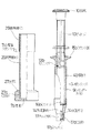
以下、図面について本発明の実施形態を詳細に説明する。図1は本発明の歯科臨床・技工作業器具の1実施形態を示す側面図である。本発明の歯科臨床・技工作業器具も従来と同様に、シリンジ6と、金属製スタンド7とからなり、歯科材料を温める際は加熱装置としてのホットプレートを使用する。
Hereinafter, embodiments of the present invention will be described in detail with reference to the drawings. FIG. 1 is a side view showing an embodiment of a dental clinical / technical work implement according to the present invention. The dental clinical / technical work implement of the present invention also comprises a
図1に示すように、シリンジ6は圧出用シリンダー本体9とこれに挿入するピストン10からなり、シリンダー本体9は、断熱性を有する耐熱性合成樹脂材料として例えば熱硬化性樹脂であるポリサルフォンで形成した胴部40の先端部に、ノズル状の注出口14aを有するポリサルフォン製の先端蓋体14を螺合により嵌め、根元端部には指掛け用のフランジ部15bを外向きに一体に突設する。
As shown in FIG. 1, the
シリンダー本体9の胴部40は一例として、長さ82mm、内径13mm、外径19.5mmの円筒状であり、胴部40と先端蓋体14との間には気密性を高めるためにパッキン14bを配置する。そして前記先端蓋体14には注出口14aを収容するキャップ体17を嵌める。このキャップ体17もポリサルフォンで形成し、注出口14aを収容する凹部17aの内周と前記注出口14aの外周とには互いに螺合するネジが切ってあり、キャップ体17が先端蓋体14に螺合状態で嵌着する。また、凹部17aの底面には気密性を高めるために内側底面にパッキン17bを配置する。
For example, the body 40 of the
ピストン10はナイロン等の合成樹脂で成形し、端部に柄10aを形成している。なお、10bは気密性を高めるためのOリングで、ピストン10の先端部の周方向の溝に嵌着した。
The
金属製スタンド7は、台部27と円筒部材26とからなり、いずれも熱伝導性の良い金属として、アルマイト処理をしたアルミニウムで形成する。台部27は、前記シリンダー本体9の先端であるキャップ体17や先端蓋体14の部分を挿入する凹部27aを上面開口として形成する。一方、円筒部材26は、外径が凹部27aの内径に等しい25mmの円筒状に形成し、円筒部材26の下端を台部27の凹部27aに圧入して金属製スタンド7を形成する。また、円筒部材26は上部外周面に熱硬化性樹脂による断熱部分28を設ける。
The
ここで、円筒部材26の厚みが2mmであるのに対し、台部27の厚みは7.5mmとより厚く形成することにより、金属製スタンド7において台部27が錘の役目を果たし、金属製スタンド7の重心を下げて、縦長の金属製スタンド7が直立状態で安定できるようにする。
Here, while the thickness of the cylindrical member 26 is 2 mm, the thickness of the base portion 27 is 7.5 mm, so that the base portion 27 serves as a weight in the
なお、本実施形態では凹部27aは底面7bを有するものとして水密な凹部としたが、他の実施形態として上下に貫通するようにすることもできる。
In the present embodiment, the
加熱装置8は図4に示すように、通電制御機構、タイマー等を内蔵させた本体の上に熱伝導性の良い金属として純銅または純アルミニウムで形成した矩形の金属製ホットプレート18を設け、該金属製ホットプレート18の裏面に部分的にヒーター19を付設した。また、金属製ホットプレート18の裏面に前記ヒーター19から少し離してサーミスタ等による温度センサー20を付設する。なお、21は電源コード、22は温度調整摘まみである。
As shown in FIG. 4, the heating device 8 is provided with a rectangular metal
次に、このような歯科臨床・技工作業器具としてのシリンジ6のシリンダー本体9に充填するのに適するよう歯科材料を整形する歯科材料用型としての、本発明の歯科材料用型について説明する。
Next, the dental material mold of the present invention will be described as a dental material mold for shaping the dental material so as to be suitable for filling the
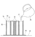
本発明の歯科材料用型の1実施形態を示す全体斜視図である図2に示すように、歯科材料用型は円柱状の柱状部材30と、柱状部材30の底面より僅かに面積の広いシート部材35とからなり、両部材とも弾性材料である剥離度の高い柔軟性シリコーンゴムにより形成する。
As shown in FIG. 2, which is an overall perspective view showing an embodiment of a dental material mold according to the present invention, the dental material mold includes a
柱状部材30は底面から上面33までの高さが、シリンジ6のシリンダー本体9の胴部40の長さよりも短い62mmであり、上面33から底面にかけて貫通して開口する歯科材料の流入空間31、32を複数設ける。また、上面33よりも2mm上方に突出する縁34を、上面33の周囲に設ける。
The
歯科材料の流入空間31は円柱状であり、その直径はシリンジ6のシリンダー本体9の胴部40の内径に等しい13mmである。なお、32は同じく歯科材料の流入空間であるが、その直径は8mmであり、内径8mmのシリンジに使用する歯科材料を整形するのに好適である。
The dental
次に、これらの歯科材料用型を使用して歯科材料の使用前準備を行う方法、及び歯科臨床・技工作業器具の使用方法について説明する。 Next, a method for preparing the dental material before use using these dental material molds and a method for using the dental clinical / technical work implement will be described.
まず、板状又は使い残しの塊状のパラフィンワックス等を薬缶に入れてコンロ又はホットプレートで温め、完全に溶融させる。次に、図3に示すように、薬缶36からパラフィンワックス等37を歯科材料の流入空間31、32に流し入れる。歯科材料用型の柱状部材30の底面にはシート部材35を敷いているため、溶融したパラフィンワックス等37により机などの作業場38が傷んでしまうことがない。また、柱状部材30とシート部材35はいずれも弾性材料であるシリコーンゴムにより形成されているため、柱状部材30の底面はシート部材35により密着して覆われ、パラフィンワックス等37が下から漏れてしまうこともない。
First, plate-shaped or unused bulk paraffin wax or the like is put in a medicine can and heated on a stove or hot plate to be completely melted. Next, as shown in FIG. 3, paraffin wax or the like 37 is poured from the medicine can 36 into the dental
また、柱状部材30の上面33の外周には縁34が存在するため、パラフィンワックス等37が歯科材料の流入空間31、32から溢れても縁34によりせき止められ、更に上面33から溢れて作業場38を汚してしまうことがない。
Further, since the
パラフィンワックス等37が冷え固まったら柱状部材30をシート部材35から外し、底面側からパラフィンワックス等37を押出す。なお、上面33上にはみ出したパラフィンワックス等37は、ナイフなどで削り取る。歯科材料の流入空間31、32は複数存在するので、一度にまとめて複数本のパラフィンワックス柱を成形することができ、効率が良い。
When the
そして固まったパラフィンワックス等37を、シリンジ6に充填する。パラフィンワックス等37は歯科材料の流入空間31、32の形状に沿って、シリンジ6のシリンダー本体9の胴部40内と同じ円柱状に成形されるため、シリンジ6に隙間なく充填することが出来、効率が良い。
The
次に、注出口14a先端にキャップ体17を嵌め、注出口14a側を下にしてシリンジ6を金属製スタンド7に挿入する。そして従来と同様に、部分的にヒーターを配設した金属製のホットプレート上に金属製スタンド7を載置して、ヒーターからの距離によって温度調節しながら金属製スタンド7を温める。金属製スタンド7はこれをホットプレート18の面上にシリンジ6を立設状態で保持したまま移動可能に載置するものであり、熱伝導性の良いアルミニウム製であるため素早く温まる。また、金属製スタンド7は円筒部材26内にシリンダー本体9を収容するケース状であるため、金属製スタンド7によってシリンダー本体9全体が覆われ、ホットプレートの熱が効率よくシリンジ6に伝わる。
Next, the spout 14a tip fitted with a
金属製スタンド7は重心の位置が低いため、シリンジ6を挿入してもホットプレート上で安定して保持することが出来る。また、金属製スタンド7は円筒部材26によりシリンジ6を収容するケース状となっているため、従来のようにシリンジ6をその先端部のみで支える場合に比べて安定性に優れる。
Since the
なお、ホットプレートが鉄製である場合には、金属製スタンド7の底面にマグネットを取り付けることにより、または、台部27を磁石とすることにより効果的に金属製スタンド7の転倒を防止することが出来る。また、前記実施形態では熱伝導性の良い金属としてのアルミニウムの例を説明したが、これを純銅等他の熱伝導性の良い金属に変えることも可能である。
Note that when the hot plate is made of iron, by attaching a magnet to the bottom surface of the
また、ホットプレートのヒーター19は温度調整摘まみ22により温度調整可能であるが、金属製ホットプレート18の面上の温度はヒーター19からの距離で異なるので、金属製ホットプレート18の面上でヒーター19の直上部分とヒーター19の直上から離れた箇所との相違で得る温度を異ならせることができる。
The temperature of the
夜間等しばらく使用しない場合の保温は、加熱装置8の金属製ホットプレート18の上方を合成樹脂製等のカバー25で覆うようにして、無駄な熱の放散を防ぐようにしてもよい。
When not in use for a while, such as at night, the upper portion of the metal
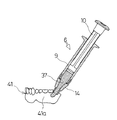
シリンジ6が充分に温まり、シリンジ6内のパラフィンワックス等37が柔らかくなったらシリンジ6を金属性スタンド7より取り出し、キャップ体17を外してピストン10を押圧して注出口14aよりパラフィンワックス等37を圧出する。
When the
例えば、図6に示すように、歯科模型41の作成において、歯肉部41aをパラフィンワックス等37で成形するのに、シリンジ6からパラフィンワックス等37を圧出・盛り付けて行うことができる。
For example, as shown in FIG. 6, in creating the
このとき、シリンダー本体9は断熱性材料であるポリサルフォンにより形成されていることから、内部のパラフィンワックス等37が冷めにくく、使用中に容易に固まってしまうのを防止することが出来る。また、シリンジ6は単層構造の樹脂製であるため、軽量で操作性が良い。
At this time, since the
6 シリンジ 7 金属製スタンド
7a 凹部 7b 底面
8 加熱装置 9 シリンダー本体
10 ピストン 10a 柄
10b Oリング 11 内管
12 隙間 13 断熱性外管
14 先端蓋体 14a 注出口
14b パッキン 15 指掛け輪体
15b フランジ部 17 キャップ体
17a 凹部 17b パッキン
18 金属製ホットプレート 19 ヒーター
20 温度センサー 21 電源コード
22 温度調整摘まみ 26 円筒部材
27 台部 27a 凹部
28 断熱部分 30 柱状部材
31、32 歯科材料の流入空間
33 上面 34 縁
35 シート部材 36 薬缶
37 パラフィンワックス等 38 作業場
40 胴部
41 歯科模型 41a 歯肉部
6
Claims (2)
Priority Applications (1)
| Application Number | Priority Date | Filing Date | Title |
|---|---|---|---|
| JP2004226576A JP3972041B2 (en) | 2004-08-03 | 2004-08-03 | Dental clinical / technical work tools and dental clinical / technical methods |
Applications Claiming Priority (1)
| Application Number | Priority Date | Filing Date | Title |
|---|---|---|---|
| JP2004226576A JP3972041B2 (en) | 2004-08-03 | 2004-08-03 | Dental clinical / technical work tools and dental clinical / technical methods |
Publications (2)
| Publication Number | Publication Date |
|---|---|
| JP2006043036A JP2006043036A (en) | 2006-02-16 |
| JP3972041B2 true JP3972041B2 (en) | 2007-09-05 |
Family
ID=36022249
Family Applications (1)
| Application Number | Title | Priority Date | Filing Date |
|---|---|---|---|
| JP2004226576A Expired - Fee Related JP3972041B2 (en) | 2004-08-03 | 2004-08-03 | Dental clinical / technical work tools and dental clinical / technical methods |
Country Status (1)
| Country | Link |
|---|---|
| JP (1) | JP3972041B2 (en) |
-
2004
- 2004-08-03 JP JP2004226576A patent/JP3972041B2/en not_active Expired - Fee Related
Also Published As
| Publication number | Publication date |
|---|---|
| JP2006043036A (en) | 2006-02-16 |
Similar Documents
| Publication | Publication Date | Title |
|---|---|---|
| EP2498653B1 (en) | Product warming device | |
| US8308480B2 (en) | Method and kit for producing a dental product | |
| US6017217A (en) | High performance dental impression tray structure | |
| US9949872B2 (en) | Therapeutic eye and eyelid cover | |
| JP3972041B2 (en) | Dental clinical / technical work tools and dental clinical / technical methods | |
| US5175008A (en) | Device for supplying plastic material for denture base and flask with the same | |
| US6204485B1 (en) | Toothpaste warmer | |
| JP2004344658A (en) | Heating device for dental material | |
| JP3013087B1 (en) | Dental clinical and technical work equipment | |
| US20110226134A1 (en) | Baby Feeding Apparatus | |
| US4370130A (en) | Wax occlusal rim warmer | |
| KR101588419B1 (en) | Heating charger for dental material by thermoelectric module | |
| US5073697A (en) | Multi-use type heating apparatus | |
| CN209257268U (en) | Liposome extruder temperature control equipment | |
| KR0135520B1 (en) | Device for supplying plantic material for dental base and | |
| GB2435687A (en) | Heater and warmer for depilatory wax | |
| CN210381330U (en) | Medical wax melting device | |
| CN212797980U (en) | Liquid medicine storage device for pharmacy | |
| JPH0736647Y2 (en) | Dental stopping carrier warmer | |
| CN203885890U (en) | Heating aromatherapy machine | |
| CA2101806A1 (en) | Heating assembly for dental materials | |
| CA1318342C (en) | Heater for dental impression compound | |
| CN204618055U (en) | Tooth glass | |
| JPH0431049Y2 (en) | ||
| CN220401988U (en) | Plaster melting heater |
Legal Events
| Date | Code | Title | Description |
|---|---|---|---|
| A977 | Report on retrieval |
Free format text: JAPANESE INTERMEDIATE CODE: A971007 Effective date: 20070215 |
|
| A131 | Notification of reasons for refusal |
Free format text: JAPANESE INTERMEDIATE CODE: A131 Effective date: 20070227 |
|
| A521 | Written amendment |
Free format text: JAPANESE INTERMEDIATE CODE: A523 Effective date: 20070426 |
|
| TRDD | Decision of grant or rejection written | ||
| A01 | Written decision to grant a patent or to grant a registration (utility model) |
Free format text: JAPANESE INTERMEDIATE CODE: A01 Effective date: 20070605 |
|
| A61 | First payment of annual fees (during grant procedure) |
Free format text: JAPANESE INTERMEDIATE CODE: A61 Effective date: 20070611 |
|
| R150 | Certificate of patent or registration of utility model |
Free format text: JAPANESE INTERMEDIATE CODE: R150 |
|
| FPAY | Renewal fee payment (event date is renewal date of database) |
Free format text: PAYMENT UNTIL: 20110615 Year of fee payment: 4 |
|
| FPAY | Renewal fee payment (event date is renewal date of database) |
Free format text: PAYMENT UNTIL: 20120615 Year of fee payment: 5 |
|
| FPAY | Renewal fee payment (event date is renewal date of database) |
Free format text: PAYMENT UNTIL: 20130615 Year of fee payment: 6 |
|
| FPAY | Renewal fee payment (event date is renewal date of database) |
Free format text: PAYMENT UNTIL: 20140615 Year of fee payment: 7 |
|
| R250 | Receipt of annual fees |
Free format text: JAPANESE INTERMEDIATE CODE: R250 |
|
| R250 | Receipt of annual fees |
Free format text: JAPANESE INTERMEDIATE CODE: R250 |
|
| R250 | Receipt of annual fees |
Free format text: JAPANESE INTERMEDIATE CODE: R250 |
|
| LAPS | Cancellation because of no payment of annual fees |