JP3971423B2 - Cylinder head gasket - Google Patents
Cylinder head gasket Download PDFInfo
- Publication number
- JP3971423B2 JP3971423B2 JP2004511722A JP2004511722A JP3971423B2 JP 3971423 B2 JP3971423 B2 JP 3971423B2 JP 2004511722 A JP2004511722 A JP 2004511722A JP 2004511722 A JP2004511722 A JP 2004511722A JP 3971423 B2 JP3971423 B2 JP 3971423B2
- Authority
- JP
- Japan
- Prior art keywords
- cylinder head
- gasket
- deformation
- head gasket
- height
- Prior art date
- Legal status (The legal status is an assumption and is not a legal conclusion. Google has not performed a legal analysis and makes no representation as to the accuracy of the status listed.)
- Expired - Fee Related
Links
Images


Classifications
-
- F—MECHANICAL ENGINEERING; LIGHTING; HEATING; WEAPONS; BLASTING
- F16—ENGINEERING ELEMENTS AND UNITS; GENERAL MEASURES FOR PRODUCING AND MAINTAINING EFFECTIVE FUNCTIONING OF MACHINES OR INSTALLATIONS; THERMAL INSULATION IN GENERAL
- F16J—PISTONS; CYLINDERS; SEALINGS
- F16J15/00—Sealings
- F16J15/02—Sealings between relatively-stationary surfaces
- F16J15/06—Sealings between relatively-stationary surfaces with solid packing compressed between sealing surfaces
- F16J15/08—Sealings between relatively-stationary surfaces with solid packing compressed between sealing surfaces with exclusively metal packing
- F16J15/0818—Flat gaskets
-
- F—MECHANICAL ENGINEERING; LIGHTING; HEATING; WEAPONS; BLASTING
- F16—ENGINEERING ELEMENTS AND UNITS; GENERAL MEASURES FOR PRODUCING AND MAINTAINING EFFECTIVE FUNCTIONING OF MACHINES OR INSTALLATIONS; THERMAL INSULATION IN GENERAL
- F16J—PISTONS; CYLINDERS; SEALINGS
- F16J15/00—Sealings
- F16J15/02—Sealings between relatively-stationary surfaces
- F16J15/06—Sealings between relatively-stationary surfaces with solid packing compressed between sealing surfaces
- F16J15/08—Sealings between relatively-stationary surfaces with solid packing compressed between sealing surfaces with exclusively metal packing
-
- F—MECHANICAL ENGINEERING; LIGHTING; HEATING; WEAPONS; BLASTING
- F02—COMBUSTION ENGINES; HOT-GAS OR COMBUSTION-PRODUCT ENGINE PLANTS
- F02F—CYLINDERS, PISTONS OR CASINGS, FOR COMBUSTION ENGINES; ARRANGEMENTS OF SEALINGS IN COMBUSTION ENGINES
- F02F11/00—Arrangements of sealings in combustion engines
-
- F—MECHANICAL ENGINEERING; LIGHTING; HEATING; WEAPONS; BLASTING
- F16—ENGINEERING ELEMENTS AND UNITS; GENERAL MEASURES FOR PRODUCING AND MAINTAINING EFFECTIVE FUNCTIONING OF MACHINES OR INSTALLATIONS; THERMAL INSULATION IN GENERAL
- F16J—PISTONS; CYLINDERS; SEALINGS
- F16J15/00—Sealings
- F16J15/02—Sealings between relatively-stationary surfaces
- F16J15/06—Sealings between relatively-stationary surfaces with solid packing compressed between sealing surfaces
- F16J15/08—Sealings between relatively-stationary surfaces with solid packing compressed between sealing surfaces with exclusively metal packing
- F16J15/0818—Flat gaskets
- F16J15/0825—Flat gaskets laminated
-
- F—MECHANICAL ENGINEERING; LIGHTING; HEATING; WEAPONS; BLASTING
- F16—ENGINEERING ELEMENTS AND UNITS; GENERAL MEASURES FOR PRODUCING AND MAINTAINING EFFECTIVE FUNCTIONING OF MACHINES OR INSTALLATIONS; THERMAL INSULATION IN GENERAL
- F16J—PISTONS; CYLINDERS; SEALINGS
- F16J15/00—Sealings
- F16J15/02—Sealings between relatively-stationary surfaces
- F16J15/06—Sealings between relatively-stationary surfaces with solid packing compressed between sealing surfaces
- F16J15/08—Sealings between relatively-stationary surfaces with solid packing compressed between sealing surfaces with exclusively metal packing
- F16J15/0818—Flat gaskets
- F16J2015/085—Flat gaskets without fold over
-
- F—MECHANICAL ENGINEERING; LIGHTING; HEATING; WEAPONS; BLASTING
- F16—ENGINEERING ELEMENTS AND UNITS; GENERAL MEASURES FOR PRODUCING AND MAINTAINING EFFECTIVE FUNCTIONING OF MACHINES OR INSTALLATIONS; THERMAL INSULATION IN GENERAL
- F16J—PISTONS; CYLINDERS; SEALINGS
- F16J15/00—Sealings
- F16J15/02—Sealings between relatively-stationary surfaces
- F16J15/06—Sealings between relatively-stationary surfaces with solid packing compressed between sealing surfaces
- F16J15/08—Sealings between relatively-stationary surfaces with solid packing compressed between sealing surfaces with exclusively metal packing
- F16J15/0818—Flat gaskets
- F16J2015/0862—Flat gaskets with a bore ring
Description
本発明は、内燃機関用のガスケットプレートを備えたシリンダヘッドガスケットであって、上記ガスケットプレートは少なくとも一枚のシートメタル層を有し、上記内燃機関は、二つの端部シリンダおよび少なくとも一個の中間シリンダを備える少なくとも一列のシリンダと、エンジンブロックと、これらのシリンダの燃焼室を覆うシリンダヘッドとを有し、当該シリンダヘッドガスケットは、シリンダヘッド用ネジにより上記シリンダヘッドと上記エンジンブロックとの間に挟持可能であり、上記ガスケットプレートは、ネジ用開口および流体用開口と、上記燃焼室の各々に対する燃焼室用開口とを備え、且つ、上記少なくとも一枚のシートメタル層は各燃焼室用開口に対し該開口を包囲する少なくとも一つのシール用ビード(sealing bead)を有し、上記ガスケットプレートの平面に対して直角な方向における上記ビードの変形は、上記ビードと同心的に延びる上記ガスケットプレートの少なくとも一つの変形制限体(deformation limiter)により制限されるシリンダヘッドガスケットに関する。このガスケットの場合、シートメタル層がシール用ビードを有し、このシートメタル層にはバネ鋼のシートが用いられる。 The present invention is a cylinder head gasket having a gasket plate for an internal combustion engine, the gasket plate having at least one sheet metal layer, the internal combustion engine comprising two end cylinders and at least one intermediate cylinder. At least one row of cylinders including cylinders, an engine block, and a cylinder head that covers combustion chambers of these cylinders, and the cylinder head gasket is interposed between the cylinder head and the engine block by a cylinder head screw. The gasket plate includes a screw opening and a fluid opening, and a combustion chamber opening for each of the combustion chambers, and the at least one sheet metal layer is provided in each combustion chamber opening. And at least one sealing bead surrounding the opening. And, the deformation of the bead in the direction perpendicular to the plane of the gasket plate, about a cylinder head gasket is limited by at least one deformation restriction element of the gasket plate extending the bead concentrically (deformation limiter). In the case of this gasket, the sheet metal layer has a sealing bead, and a spring steel sheet is used for the sheet metal layer.
本発明は、全ての燃焼室の軸線が一つの平面を画成するという所謂インラインエンジン用のシリンダヘッドガスケットに関するだけでなく、(例えば各シリンダバンクが一列に配置された数個の燃焼室と一つのシリンダヘッドとを有する)V型エンジン等の所謂シリンダバンクを幾つか備えたエンジンのシリンダヘッドガスケットにも関する。更に、当該シリンダヘッドガスケットは、各燃焼室の軸線が相互に平行であるが単一平面内には配置されないという形態で一列のシリンダの連続的な燃焼室が互いにオフセットされるように配置される内燃機関に対しても適している。また端部シリンダとはシリンダ列の端部にそれぞれ配置された二つのシリンダを意味し、中間シリンダとはシリンダ列の両方の端部シリンダ間に配置されたシリンダを意味する。したがって本発明のシリンダヘッドガスケットは、少なくとも三つの燃焼室用開口を有する。 The invention relates not only to cylinder head gaskets for so-called in-line engines in which all combustion chamber axes define a single plane, but also to several combustion chambers (for example several cylinders arranged in a row). It also relates to a cylinder head gasket of an engine with several so-called cylinder banks, such as a V-type engine (with two cylinder heads). Furthermore, the cylinder head gasket is arranged such that the continuous combustion chambers of a row of cylinders are offset from each other in such a manner that the axes of the combustion chambers are parallel to each other but are not arranged in a single plane. Also suitable for internal combustion engines. The end cylinder means two cylinders arranged at the end of the cylinder row, and the intermediate cylinder means a cylinder arranged between both end cylinders of the cylinder row. Accordingly, the cylinder head gasket of the present invention has at least three combustion chamber openings.
通常、シリンダヘッドをエンジンブロックに連結すると共にこれらの二つの構成要素間にシリンダヘッドガスケットを挟持する役割を果たすシリンダヘッド用ネジは、各燃焼室の近傍に四つのシリンダヘッド用ネジが位置するように配置される。燃焼室の近傍のシリンダヘッド用ネジについて(燃焼室の軸線方向に見て)エンジンブロックの平面図内で考察し、且つ角度α(燃焼室またはシリンダバンクの軸線に沿って延びるエンジンブロックの長手中心面においては0°および360°であり且つ燃焼室の軸線の回りで時計回りに増加する角度)を各シリンダヘッド用ネジの位置を決めるために導入したとすれば、四本のシリンダヘッド用ネジは約45°、約135°、約225°および約315°に配置され、このことは燃焼室用開口の近傍にあるシリンダヘッドガスケットの各ネジ用開口に対しても同様である。以下の説明において、燃焼室用開口に隣接し且つネジ用開口の近傍であるシリンダヘッドガスケットの領域をネジ近傍領域と称し、且つ、燃焼室用開口に隣接し且つ各ネジ近傍領域間に位置するガスケットの領域をネジ間領域と称する。但し、最近の内燃機関(エンジン)の場合、四本のシリンダヘッド用ネジは各燃焼室に対して配備されてはおらず、エンジンブロックおよびシリンダヘッドにおいて互いに隣り合った燃焼室によって形成される二つの薄肉部(web)のそれぞれには一本のみのシリンダヘッド用ネジが配置されることから、中間シリンダの近傍の四本のシリンダヘッド用ネジはその中間シリンダに対してだけでなくその中間シリンダの近傍の二つの燃焼室に対しても割当てられる。各燃焼室が、燃焼室の軸線を貫通して延びる分割平面であって全ての燃焼室の軸線により画成されるシリンダ列の長手中心面に対して直角に延びる分割平面により細分されるものとし、且つ、その結果生じる燃焼室半体について上記シリンダヘッド用ネジにより生成される挟持力であって燃焼室半体に隣接するシリンダヘッドガスケットの領域に作用する挟持力に関して考察すると、全てのシリンダヘッド用ネジが同一トルクで締着されると仮定すれば、端部シリンダの外側燃焼室半体に対応する挟持力は、端部シリンダの内側燃焼室半体に対応する挟持力または中間シリンダの両燃焼室半体に対応する挟持力の二倍である。故にこの理由のみにより、挟持されたシリンダヘッドガスケットに作用する挟持力または押圧力は全体的に同一の強さではなく、一つまたは複数の中間シリンダの領域および端部シリンダの内側燃焼室半体の領域におけるよりもシリンダ列の長手端部の領域における方が大きい。すなわち、エンジンブロックおよびシリンダヘッドは挟持力の考察に対しては完全に剛性の構成要素としては取り扱われ得ないという理由により、エンジンの場合においてエンジンブロックおよびシリンダヘッドは(シリンダヘッド用ネジのボアが無視されるなら)燃焼室の外側に何らの凹所もキャビティも有さないと仮定すれば、シリンダヘッド用ネジによりもたらされ且つ挟持されたシリンダヘッドガスケットに作用する押圧力は、エンジンブロックおよびシリンダヘッドの弾性変形能力の結果として、シリンダヘッド用ネジからの距離が増大するにつれて減少し、且つ、シリンダ列の横手中心面(シリンダ列の延びる方向において中心であって横方向に延びる平面)からの距離が増大するにつれて増加する。 Normally, the cylinder head screws that connect the cylinder head to the engine block and sandwich the cylinder head gasket between these two components are positioned so that four cylinder head screws are located near each combustion chamber. Placed in. The cylinder head screw near the combustion chamber is considered in the plan view of the engine block (as viewed in the axial direction of the combustion chamber) and the angle α (longitudinal center of the engine block extending along the axis of the combustion chamber or cylinder bank) The angle of 0 ° and 360 ° in the plane and increasing clockwise around the axis of the combustion chamber) is introduced to determine the position of each cylinder head screw. Are located at about 45 °, about 135 °, about 225 °, and about 315 °, as is the case with each screw opening in the cylinder head gasket in the vicinity of the combustion chamber opening. In the following description, the area of the cylinder head gasket that is adjacent to the combustion chamber opening and in the vicinity of the screw opening is referred to as a screw vicinity area, and is adjacent to the combustion chamber opening and located between the screw vicinity areas. The area of the gasket is referred to as an inter-screw area. However, in the case of a recent internal combustion engine (engine), four cylinder head screws are not provided for each combustion chamber, but two engine chambers and cylinder heads are formed by two adjacent combustion chambers. Since only one cylinder head screw is arranged in each thin section (web), the four cylinder head screws in the vicinity of the intermediate cylinder are not only for the intermediate cylinder but also for the intermediate cylinder. It is also assigned to two adjacent combustion chambers. Each combustion chamber shall be subdivided by a dividing plane extending through the axis of the combustion chamber and extending perpendicular to the longitudinal center plane of the cylinder row defined by all combustion chamber axes. In addition, when considering the clamping force generated by the cylinder head screw with respect to the resulting combustion chamber half and acting on the region of the cylinder head gasket adjacent to the combustion chamber half, all cylinder heads are considered. Assuming that the screws are fastened with the same torque, the clamping force corresponding to the outer combustion chamber half of the end cylinder is either the clamping force corresponding to the inner combustion chamber half of the end cylinder or both intermediate cylinders. It is twice the clamping force corresponding to the combustion chamber half. Therefore, for this reason alone, the clamping force or pressing force acting on the clamped cylinder head gasket is not of the same overall strength, but the area of one or more intermediate cylinders and the inner combustion chamber half of the end cylinder. This is larger in the region at the longitudinal end of the cylinder row than in this region. That is, in the case of an engine, the engine block and cylinder head (bore of the cylinder head screw bore) are because the engine block and cylinder head cannot be handled as a completely rigid component for the consideration of clamping force. Assuming that there are no recesses or cavities outside the combustion chamber (if ignored), the thrust exerted by the cylinder head screws and acting on the clamped cylinder head gasket is the engine block and As a result of the elastic deformation capacity of the cylinder head, it decreases as the distance from the cylinder head screw increases, and from the lateral center plane of the cylinder row (a plane extending in the center and laterally extending in the direction in which the cylinder row extends). Increases as the distance increases.
レシプロ式内燃機関が動作する間、シリンダヘッドガスケットを収容するエンジンブロックとシリンダヘッドとの間のシール間隙の幅は、各シリンダの作動サイクルの関数として周期的に変化し、このためシリンダヘッドガスケットはエンジン作動中において一定の圧力変化を受ける。冒頭で言及した形式である本発明の前提のシリンダヘッドガスケットの場合、燃焼室用開口の回りのシールは、燃焼室用開口を包囲するシール用ビードにより少なくとも本質的にもたらされると共に、上述したようにシール間隙が変化するので完全なシールを維持すべく永続的なスプリング弾性特性を有さねばならない。すなわち、長期のエンジン作動後でさえもシール用ビードはガスケットプレートの平面に対して直角な方向において依然としてスプリング弾性形態で変形することができなければならない。これを確実にするために、冒頭で言及した形式である本発明の前提のシリンダヘッドガスケットは各燃焼室開口に対し、該燃焼室用開口に対応するシール用ビードの起こり得る変形(すなわちそのスプリング撓曲)を制限する少なくとも一つの変形制限体を有し、シール用ビードを容認し得ないほどの大きな変形から保護する。なお、このような変形制限体をストッパとも称す。このようなストッパは多くの場合、シール用ビードの径方向外方または径方向内方にて、該シール用ビードが形成されたシートメタル層に対して取付けられた円形金属リングの形状を有する。ガスケットプレートが多層である場合には、シリンダヘッドガスケットが所定位置に挟持されたときにシール用ビードを備えたシートメタル層に対してストッパが当接するようにこのビードの径方向内側または径方向外側において当該ストッパを上記シートメタル層に隣接するシートメタル層にも取付けてもよい。更に、この形式のストッパに対する付加的実施形態は、後に詳述する例えば米国特許第5713580号(US-5,713,580-A)などの現状技術から公知である。この公報の図2は金属製である三層のシリンダヘッドガスケットを示しており、これに依れば二つの外側層のそれぞれは各燃焼室用開口の回りにおいて、他方のシール用ビードと対向するように配置されると共に内側層に向かう方向に突出するシール用ビードを備え、上記内側層は二つの外側層間に配置されると共に、シリンダヘッドガスケットが所定位置に挟持されたときに該内側層上には上記の二つのシール用ビードが当接する。上記内側層は燃焼室用開口に関して径方向に所定距離で終端すると共に、燃焼室用開口に対向する該内側層の縁部に金属ストッパリングが繋止される。このストッパリングは、径方向においてシール用ビードの内側に配置され、且つ上記内側層よりも厚寸であって上記内側層の両主要表面を越えて二つの外側層に向かう方向に突出する。したがって、上記ガスケットプレートの平面に対して直角に測定され且つビード変形を制限するために利用可能である有効高さは、内側層の主要表面を越えた上記ストッパの突出量に等しいものであり、上記ストッパリングの全厚でも高さでもない。上記米国特許第5713580号(US-5,713,580-A)に係るシリンダヘッドガスケットの場合、挟持されたシリンダヘッドガスケットに作用する押圧力がシリンダヘッド用ネジからの距離が増大するにつれて減少することが考慮されており、このように押圧力が減少するのは、ガスケットプレートの平面に対して直角に測定され且つビード変形を制限するために利用可能である上記ストッパリングの高さがシリンダヘッド用ネジからの距離の関数である高さ変移(height profile)を有すること、すなわち(ガスケットプレートの平面に直角にシリンダヘッドガスケットを見た場合に)局所的に変化する上記ストッパリングの有効高さがシリンダヘッド用ネジからの距離に依存することによる。 During operation of a reciprocating internal combustion engine, the width of the seal gap between the engine block containing the cylinder head gasket and the cylinder head changes periodically as a function of the operating cycle of each cylinder, so that the cylinder head gasket is Subject to constant pressure changes during engine operation. In the case of the inventive cylinder head gasket of the type mentioned at the outset, the seal around the combustion chamber opening is at least essentially provided by a sealing bead surrounding the combustion chamber opening, as described above. As the seal gap changes, it must have a permanent spring elasticity to maintain a perfect seal. That is, even after prolonged engine operation, the sealing bead must still be able to deform in a spring resilient configuration in a direction perpendicular to the plane of the gasket plate. To ensure this, the cylinder head gasket of the present invention, of the type mentioned at the outset, has for each combustion chamber opening a possible deformation of the sealing bead corresponding to the combustion chamber opening (ie its spring). It has at least one deformation limiting body that limits bending) and protects the sealing bead from unacceptably large deformation. Such a deformation limiting body is also referred to as a stopper. Such stoppers often have the shape of a circular metal ring attached to the sheet metal layer on which the sealing bead is formed, either radially outward or radially inward of the sealing bead. When the gasket plate is multi-layered, the bead is radially inward or radially outward so that the stopper contacts the sheet metal layer with the sealing bead when the cylinder head gasket is held in place. The stopper may be attached to a sheet metal layer adjacent to the sheet metal layer. Furthermore, additional embodiments for this type of stopper are known from the state of the art such as US Pat. No. 5,713,580 (US-5,713,580-A), which will be described in detail later. FIG. 2 of this publication shows a three-layer cylinder head gasket made of metal, according to which each of the two outer layers faces the other sealing bead around each combustion chamber opening. And a sealing bead protruding in the direction toward the inner layer, the inner layer being disposed between the two outer layers and on the inner layer when the cylinder head gasket is held in place. The two sealing beads are in contact with each other. The inner layer terminates at a predetermined distance in the radial direction with respect to the combustion chamber opening, and a metal stopper ring is secured to the edge of the inner layer facing the combustion chamber opening. The stopper ring is disposed inside the sealing bead in the radial direction, and is thicker than the inner layer and protrudes in a direction toward the two outer layers beyond both main surfaces of the inner layer. Thus, the effective height measured perpendicular to the plane of the gasket plate and available to limit bead deformation is equal to the amount of protrusion of the stopper beyond the major surface of the inner layer; It is not the full thickness or height of the stopper ring. In the case of the cylinder head gasket according to US Pat. No. 5,713,580 (US-5,713,580-A), it is considered that the pressing force acting on the sandwiched cylinder head gasket decreases as the distance from the cylinder head screw increases. This reduction in pressing force is due to the fact that the height of the stopper ring, measured at right angles to the plane of the gasket plate and available to limit bead deformation, from the cylinder head screw. Have a height profile that is a function of distance, i.e. the effective height of the stopper ring, which varies locally (when looking at the cylinder head gasket perpendicular to the plane of the gasket plate), for the cylinder head By depending on the distance from the screw.
本発明は冒頭で言及された形式のシリンダヘッドガスケットに関するが、これによればガスケットプレートの平面に対して直角に測定され且つシール用ビードの変形を制限するために利用可能である各変形制限体の有効高さは、その円周に亘って平均された平均値(以下、高さ平均値と称す)を有するが、このことは各変形制限体または一つの変形制限体の高さがその円周に沿って変化することを意図するものではない。よって、仮に変形制限体の円周に沿った変形制限体の高さが一定であれば、この一定の高さは上記高さ平均値に等しいものとなる。 The present invention relates to a cylinder head gasket of the type mentioned at the outset, according to which each deformation limiter is measured perpendicular to the plane of the gasket plate and can be used to limit the deformation of the sealing bead. Effective height has an average value averaged over its circumference (hereinafter referred to as height average value), which means that the height of each deformation limiting body or one deformation limiting body is the circle. It is not intended to change along the circumference. Therefore, if the height of the deformation limiting body along the circumference of the deformation limiting body is constant, this constant height is equal to the average height value.
最近のレシプロ式内燃機関の開発傾向はより軽量な構造にすること向けられ、これにより、特にシリンダヘッドに対して軽量金属合金を使用する結果となっただけでなく、特にエンジンブロックの燃焼室および他のキャビティの回りにおける壁厚が相当に薄くされる結果となった。しかしながら、その結果、特にエンジンブロックは次第に変形し易くなり、すなわち、シリンダヘッド用ネジが締着されたときに生ずるエンジンブロック(ならびにシリンダヘッド)の弾性変形は相当に大きなものとなり、これによりシリンダヘッド用ネジによりもたらされてシリンダヘッドガスケットに作用する押圧力の減少はシリンダヘッド用ネジからの距離が長くなるにつれて相当に大きなものとなる。エンジン構成部品であるエンジンブロックおよびシリンダヘッドの材料応力(特に、シリンダヘッド用ネジにより引き起こされる歪み)をできるだけ小さく維持するために、シリンダヘッド用ネジに及ぼされる力をできるだけ小さくするように付加的に対処することが試みられている。これらの開発傾向は一定の状況において、一つの中間シリンダの燃焼室回りまたは複数の中間シリンダの燃焼室回りにおいてシリンダヘッドガスケットにより行われるシールが保証されないという事実に繋がる。このため本発明の基礎を為す目的は、一つの中間シリンダまたは複数の中間シリンダにおけるシールの品質が改善されるように、上記で定義された形式のシリンダヘッドガスケットすなわち請求項1の前文に係るシリンダヘッドガスケットを改良することにある。
Recent development trends in reciprocating internal combustion engines have been directed to lighter structures, which not only resulted in the use of lightweight metal alloys, especially for the cylinder head, but also the combustion chambers of the engine block and The wall thickness around the other cavities was considerably reduced. However, as a result, the engine block in particular tends to be gradually deformed, that is, the elastic deformation of the engine block (and the cylinder head) that occurs when the cylinder head screw is tightened is considerably large, which makes the cylinder head The reduction of the pressing force caused by the working screw and acting on the cylinder head gasket becomes considerably larger as the distance from the cylinder head screw becomes longer. In order to keep the material stress (especially the strain caused by the cylinder head screw) of the engine block and cylinder head, which are engine components, as small as possible, the force exerted on the cylinder head screw is additionally reduced as much as possible. There are attempts to deal with it. These development trends lead to the fact that, in certain circumstances, the sealing performed by the cylinder head gasket around the combustion chamber of one intermediate cylinder or around the combustion chambers of a plurality of intermediate cylinders is not guaranteed. For this reason, the object of the present invention is to provide a cylinder head gasket of the type defined above, i.e. a cylinder according to the preamble of
本発明によればこの目的は、端部シリンダに関連する変形制限体の高さ平均値が、それぞれ、一つの中間シリンダまたは複数の中間シリンダに関連する一つの付加的変形制限体または複数の付加的変形制限体の高さ平均値よりも小さくなるような高さ変移を有することで達成される。 According to the invention, the object is that the average height of the deformation limiter associated with the end cylinder is one additional deformation limiter or a plurality of additional deformations associated with one intermediate cylinder or a plurality of intermediate cylinders, respectively. This is achieved by having a height transition that is smaller than the average height of the static deformation limiter.
シリンダヘッドガスケットの設置の間、すなわち(燃焼室内における一切の燃焼圧力なしで)シリンダヘッド用ネジを締着する間、シール用ビードは、上記変形制限体(ストッパ)が圧力を受ける程度までスプリング弾性形態で平たくせしめられる。上記端部シリンダに対応する変形制限体が低いため、本発明のガスケットの場合、中間シリンダに対応するシール機構(ビードおよび変形制限体)に作用する押圧力は各変形制限体の高さが同一であるシリンダヘッドガスケットと比較して大きなものとなり、すなわち、押圧力はシリンダヘッドガスケット全体に亘って均一化される。上述したように、本発明のシリンダヘッドガスケットの場合、この効果を得る上で上記変形制限体はその円周の全体に亘って高さ変移を有する必要はなく、すなわち後述するように他の実施形態が好適であるとしても個々の変形制限体を考慮する場合にはその有効高さをその円周全体に亘って一定とすることもできる。また個々の燃焼室用開口を包囲するシール用ビードの全てが同一高さである必要がないことは勿論である。シリンダヘッドは、該シリンダヘッドの各長手端部間においてシリンダヘッドガスケットによりシールされるシール間隙がエンジンブロック(より正確にはシリンダ列)の横手中心面に向かう方向において高さが高くなるように、燃焼室からの高い気体圧力の作用により膨出する傾向があることから、種々のシール用ビードは、中間シリンダに対応するシール用ビードの高さが端部シリンダに対応するシール用ビードの高さより高くなるように、当該シール用ビードの高さが上記横手中心面に向かう方向に高くなっていくように設計されることが望ましい。スプリング弾性的なシール用ビードはいずれもエンジン作動中における圧力から完全に解放されないのではなく、各シール用ビードが弾性的にのみ変形される程度まで且つエンジン作動中に生ずる最大の燃焼室圧力が生じた場合でさえも燃焼室回りのシールを保証し得る程度まで解放されるようにすべきである。 During installation of the cylinder head gasket, that is, while tightening the cylinder head screw (without any combustion pressure in the combustion chamber), the sealing bead is spring-elastic to the extent that the deformation limiter (stopper) is subjected to pressure. Flattened in form. Since the deformation limiter corresponding to the end cylinder is low, in the case of the gasket of the present invention, the pressure acting on the seal mechanism (bead and deformation limiter) corresponding to the intermediate cylinder is the same as the height of each deformation limiter. In other words, the pressing force is made uniform over the entire cylinder head gasket. As described above, in the case of the cylinder head gasket of the present invention, in order to obtain this effect, the deformation limiting body does not need to have a height shift over the entire circumference, that is, as described later, Even if the form is suitable, the effective height can be made constant over the entire circumference in the case of considering individual deformation restrictors. Of course, it is not necessary that all of the sealing beads surrounding the individual combustion chamber openings have the same height. The cylinder head has a height such that the seal gap sealed by the cylinder head gasket between the longitudinal ends of the cylinder head increases in the direction toward the lateral center surface of the engine block (more precisely, the cylinder row). Since various sealing beads tend to swell due to the action of high gas pressure from the combustion chamber, the height of the sealing bead corresponding to the intermediate cylinder is higher than the height of the sealing bead corresponding to the end cylinder. It is desirable that the height of the sealing bead is designed so as to increase in the direction toward the transverse center plane. Neither spring elastic sealing bead is completely relieved from the pressure during engine operation, but the maximum combustion chamber pressure that occurs during engine operation to the extent that each sealing bead is only elastically deformed. Even if it occurs, it should be released to the extent that it can guarantee a seal around the combustion chamber.
本発明のシリンダヘッドガスケットの場合、上記変形制限体はシリンダヘッドガスケットの局所的隆起部を形成するが、これら局所的隆起部はそれぞれ各燃焼室用開口の回りに延び、且つ、これら局所的隆起部の有効高さは、シリンダヘッド用ネジにより生成される挟持力が端部シリンダの近傍の領域から一つの中間シリンダまたは複数の中間シリンダの近傍の領域へと部分的に伝達されることで、ガスケットプレートの平面に対して直角に延びる挟持力、すなわちシール力が一つの中間シリンダまたは複数の中間シリンダ回りで大きくなるように構成される。上記シリンダヘッド用ネジに所定の締着トルクを加えた場合、押圧力は端部シリンダの領域において小さいものとされ、結果として付加的利点が得られる。例えばシリンダヘッドが軽量金属合金から生成され且つエンジンブロックが灰色鋳鉄から生成される等、シリンダヘッドとエンジンブロックとが異なる材料から生成されると、異なる熱膨張率によりエンジン作動中に、シリンダヘッドのシール表面とエンジンブロックのシール表面との間のシフト移動が起こりシール間隙を制限することは避けられない。これらシフト移動はシリンダヘッドの長手端部の領域において最大である(シリンダ列の横手中心面の領域においてこのようなシフト移動は生じない)ことから、これらシール表面だけでなくシリンダヘッドガスケットにおける摩擦による摩耗および裂開は本発明により低減せしめられる。これは、習用のエンジンと比較して、シリンダヘッドの各長手端部の領域において上記シリンダヘッドガスケットとシリンダヘッドおよびエンジンブロックの各シール表面との間にはより小さな押圧力が生ずるからである。 In the case of the cylinder head gasket of the present invention, the deformation restrictor forms local ridges of the cylinder head gasket, each of these local ridges extending around each combustion chamber opening, and these local ridges. The effective height of the portion is such that the clamping force generated by the cylinder head screw is partially transmitted from a region near the end cylinder to a region near one intermediate cylinder or a plurality of intermediate cylinders, The sandwiching force extending at right angles to the plane of the gasket plate, that is, the sealing force, is configured to increase around one intermediate cylinder or a plurality of intermediate cylinders. When a predetermined tightening torque is applied to the cylinder head screw, the pressing force is small in the region of the end cylinder, resulting in additional advantages. If the cylinder head and engine block are made of different materials, for example, the cylinder head is made of a lightweight metal alloy and the engine block is made of gray cast iron, the cylinder head will It is inevitable that a shift movement occurs between the seal surface and the seal surface of the engine block to limit the seal gap. Since these shift movements are maximum in the region of the longitudinal end of the cylinder head (no such shift movement occurs in the region of the lateral center plane of the cylinder row), the friction is caused not only by these seal surfaces but also by the cylinder head gasket. Wear and tear are reduced by the present invention. This is because a smaller pressing force is generated between the cylinder head gasket and the cylinder head and the seal surfaces of the engine block in the region of each longitudinal end of the cylinder head as compared to a conventional engine.
上述したように本発明により達成されるべき目的は原則的に、全周に亘って一定の有効高さを有する変形制限体によっても達成可能であり、その場合に端部シリンダに対応する変形制限体の有効高さは、少なくとも一つの付加的変形制限体の有効高さよりも低い。しかしながら、ガスケットの上記横手中心面から変形制限体に対応する燃焼室用開口の中心までの距離が長くなるにつれて、変形制限体の高さの平均値が小さくなるように各変形制限体が高さ変移を有するという実施形態が更に良好である。なお、シリンダヘッドガスケットの上記長手中心面はガスケットプレートの平面に対して直角に且つ各燃焼室用開口の中心を貫通して延びる平面であり、シリンダヘッドガスケットの上記横手中心面はこれらの二つの平面に対して直角に延びると共に各端部シリンダに対応する燃焼室用開口の中心から等距離な平面である。 As mentioned above, the object to be achieved by the present invention can in principle also be achieved by a deformation limiter having a constant effective height over the entire circumference, in which case the deformation limit corresponding to the end cylinder. The effective height of the body is lower than the effective height of the at least one additional deformation limiter. However, as the distance from the lateral center plane of the gasket to the center of the combustion chamber opening corresponding to the deformation limiting body becomes longer, the height of each deformation limiting body becomes smaller so that the average value of the height of the deformation limiting body becomes smaller. Embodiments with transitions are even better. The longitudinal center plane of the cylinder head gasket is a plane extending at right angles to the plane of the gasket plate and penetrating through the center of each combustion chamber opening. The plane extends at a right angle to the plane and is equidistant from the center of the combustion chamber opening corresponding to each end cylinder.
上述したように、シリンダヘッド用ネジにより生成されて上記シリンダヘッドガスケットに作用する押圧力は、シリンダヘッドガスケットから考察したときに軽視すべきでないエンジンブロックおよびシリンダヘッドの弾性変形能力を考慮するとシリンダヘッド用ネジからの距離が長くなるにつれて一次近似で減少し、上記エンジンブロックおよびシリンダヘッドという二つの構成要素がシリンダヘッド用ネジにより互いに連結され且つ互いに対して張設される箇所においてエンジンブロックおよびシリンダヘッドの剛性は最大である。しかしながら、特にエンジンブロックのだけではなく場合によってはシリンダヘッドの局所的「限界領域(critical area)」もまた、設置されたシリンダヘッドガスケットに作用する局所変化的押圧力に影響を及ぼす。これら構成要素が例えば冷却水およびエンジンオイル用の通路等のキャビティを有する場合、これら構成要素の剛性は小さく、すなわち、このようなキャビティが無い領域よりも変形し易い。エンジンブロックおよび/またはシリンダヘッドの局所的に変化する構成要素剛性を考慮するために、(エンジンが動作温度に到達していない冷間時に)シリンダヘッドガスケットが所定位置に挟持された場合に上記変形制限体の円周に沿って該変形制限体に作用する圧力が均一化されて該変形制限体の円周に沿って比較的に僅かな圧力の変化のみができるようにシリンダヘッドガスケットが所定位置に挟持されたときに、少なくとも一つの変形制限体(好ましくは全ての変形制限体)がその円周に沿って、エンジンブロックおよび/またはシリンダヘッドの局所的で可変的に減少する構成要素剛性に応じて、高さ変移を有するように本発明のシリンダヘッドガスケットを設計することが提案される。このような本発明のシリンダヘッドガスケットの実施形態では、シリンダヘッド用ネジからの距離が長くなることに伴う圧力の減少だけでなく、例えば冷却水またはエンジンオイル用の通路が燃焼室に近接して配置された場合等においてエンジンブロックおよび/またはシリンダヘッドの構成要素剛性がキャビティまたは近傍キャビティにより減少する箇所における圧力の局所的減少をも考慮している。したがって、一次近似において変形制限体の有効高さは、上記ネジに近い領域における方が上記で定義されたネジ間領域におけるよりも小さいが、この高さ変移に、「限界領域」を考慮すると共にこれら「限界領域」が存在しない場合よりもこのような「限界領域」の近傍において変形制限体の有効高さがより大きくなるようにする高さ変移が重ね合わされるのが好ましい。 As described above, the pressing force generated by the cylinder head screw and acting on the cylinder head gasket should be considered when considering the elastic deformation capacity of the engine block and the cylinder head when considering from the cylinder head gasket. The engine block and the cylinder head are reduced at a first order approximation as the distance from the engine screw becomes longer, and the two components, the engine block and the cylinder head, are connected to each other by the cylinder head screw and are stretched with respect to each other. The rigidity of is the maximum. However, in particular not only the engine block, but in some cases the local “critical area” of the cylinder head also affects the locally varying pressing force acting on the installed cylinder head gasket. If these components have cavities such as passages for cooling water and engine oil, for example, these components are less rigid, i.e. they are more likely to deform than regions without such cavities. To account for locally varying component stiffness of the engine block and / or cylinder head, the above deformation occurs when the cylinder head gasket is clamped in place (during cold when the engine has not reached operating temperature) The cylinder head gasket is positioned at a predetermined position so that the pressure acting on the deformation restricting body is made uniform along the circumference of the restricting body so that only a relatively small pressure change can be made along the circumference of the deformation restricting body. At least one deformation limiter (preferably all deformation limiters) when sandwiched between the engine block and / or the component stiffness of the cylinder head that decreases locally and variably along its circumference. Accordingly, it is proposed to design the cylinder head gasket of the present invention to have a height transition. In the embodiment of the cylinder head gasket according to the present invention, not only the pressure decreases as the distance from the cylinder head screw increases, but also, for example, a passage for cooling water or engine oil is provided close to the combustion chamber. It also takes into account a local decrease in pressure where the component stiffness of the engine block and / or cylinder head is reduced by the cavities or nearby cavities, such as when deployed. Therefore, in the first-order approximation, the effective height of the deformation limiting body is smaller in the region close to the screw than in the inter-screw region defined above. It is preferable to superimpose a height transition so that the effective height of the deformation limiting body is larger in the vicinity of the “limit region” than when these “limit regions” do not exist.
この点に関し、シリンダヘッドガスケットというものは特定のエンジンに対して構成されることからエンジンブロックおよびシリンダヘッドの局所的に変化する構成要素剛性はガスケットの設計技師に対して指定されると共に、本発明の高さ変移設定(heght profiling)は公知の有限要素法により計算され得ることを銘記されたい。 In this regard, since a cylinder head gasket is configured for a particular engine, locally varying component stiffness of the engine block and cylinder head is specified to the gasket engineer and the present invention. Note that the height profiling of can be calculated by known finite element methods.
念のため、局所的で可変的に減少する構成要素剛性を考慮して達成される高さ変移は本発明の基本的着想に係るすなわち請求項1に係る「長手変移(longitudinal profile)」に重ね合わされるべきであり、すなわち、請求項1または請求項2において定義され且つ請求項3において定義されているような割合決定に対する法則は好適な実施形態に対しては相互に組み合わされるべきことも指摘しておく。
As a precaution, the height transition achieved in view of the locally and variably decreasing component stiffness is superimposed on the “longitudinal profile” according to the basic idea of the invention,
独国特許第4142600号(DE-41 42 600-C2)からは、燃焼室用開口を包囲すると共に、エンジンブロックおよび/またはシリンダヘッドの局所的で可変的に減少する構成要素剛性に応じた高さ変移を有するシリンダヘッドガスケットの燃焼室シール要素が得られる。 German Patent No. 4142600 (DE-41 42 600-C2) encloses the combustion chamber opening and increases the local stiffness of the engine block and / or cylinder head to a variable component stiffness. A combustion chamber sealing element of a cylinder head gasket with a profile shift is obtained.
レシプロ式内燃機関が作動する間、各燃焼室内に発生する熱は、特に燃焼室を包囲するエンジンブロックの領域から様々な度合にて一定領域へと放出される。上記熱の放出は、一方では燃焼室の直近であり且つ他方では冷却水用の通路から相当の距離を有する領域から特に不都合に行われる。上記加熱および熱の放出に関して特に重要なのは、相互に接近して配置された燃焼室間の狭幅薄肉部、より正確には壁部の領域である。比較的に熱放出が少ない領域ではエンジンの作動中に熱膨張が大きく、これにより、エンジンブロックとシリンダヘッドとの間のシール間隙の大きさまたは高さが一定領域において小さいものとなり、よってシリンダヘッドガスケットに対する圧力が一定領域において高いものとなる。この状況はこれまで実際には考慮されておらず、逆に変形制限体は、シリンダヘッドガスケットの隣り合った燃焼室開口間の狭幅の薄肉部の領域において他の領域よりも大きな高さを有するように、互いに接近して配置された燃焼室間の狭幅の薄肉部または壁部の領域において特にエンジンブロックの構成要素剛性が小さいことを考慮して設計されていた。そこで、エンジンの作動中に局所的に変化して生ずる熱膨張をも考慮するために、シリンダヘッドガスケットが所定位置に挟持されて内燃機関の作動温度において変形制限体に作用する圧力が該変形制限体の円周に沿って均一化されるように、少なくとも一つの変形制限体がその円周に沿って、内燃機関の作動温度により予測されるエンジンブロックおよび/またはシリンダヘッドの局所的に変化する熱膨張に応じた高さ変移を有するように、本発明のシリンダヘッドガスケットが設計されることが提案される。したがって、本発明の基本的着想に基づいて寸法設定された変形制限体と比較して、熱膨張の大きな箇所において上記変形制限体の有効高さが小さいものとせしめられる。この点に関して便宜的には、内燃機関の全負荷の約60〜100%において予測される熱膨張、より望ましくは永続的な全負荷に対して予測されるべき熱膨張が考慮される。一方、予測されるこれらの熱膨張の全ては、有限要素分析により計算されてもよい。また、局所的に変化する熱膨張を考慮した高さ変移設定は、本発明の基本的着想に係るすなわち請求項1または請求項2に係る長手変移設定、場合によって請求項3に係る変移設定に対しても重ね合わせられることは勿論である。
During the operation of the reciprocating internal combustion engine, the heat generated in each combustion chamber is released to a certain region at various degrees, particularly from the region of the engine block surrounding the combustion chamber. The release of the heat takes place particularly inconveniently on the one hand in the immediate vicinity of the combustion chamber and on the other hand from a region which has a considerable distance from the cooling water passage. Of particular importance with regard to the heating and the release of heat is the narrow, thin wall, more precisely the region of the wall, between the combustion chambers placed close to each other. In areas where there is relatively little heat release, thermal expansion is large during engine operation, which reduces the size or height of the seal gap between the engine block and the cylinder head in certain areas, and thus the cylinder head. The pressure on the gasket is high in a certain region. This situation has not been taken into account so far, and conversely, the deformation limiter has a higher height in the narrow thin region between adjacent combustion chamber openings of the cylinder head gasket than in other regions. As described above, the engine block was designed in consideration of the small rigidity of the engine block, particularly in the narrow thin wall portion or the wall portion region between the combustion chambers arranged close to each other. Therefore, in order to take into account the thermal expansion caused by local changes during the operation of the engine, the pressure acting on the deformation limiting body at the operating temperature of the internal combustion engine with the cylinder head gasket held between the predetermined positions is The at least one deformation limiter varies locally along the circumference of the engine block and / or cylinder head as predicted by the operating temperature of the internal combustion engine so that it is uniform along the circumference of the body. It is proposed that the cylinder head gasket of the present invention be designed to have a height transition in response to thermal expansion. Therefore, the effective height of the deformation limiting body is small at a location where the thermal expansion is large as compared with the deformation limiting body dimensioned based on the basic idea of the present invention. Conveniently in this regard, the expected thermal expansion at about 60-100% of the full load of the internal combustion engine, more preferably the thermal expansion to be predicted for a permanent full load, is considered. On the other hand, all of these predicted thermal expansions may be calculated by finite element analysis. Further, the height transition setting in consideration of the locally changing thermal expansion is based on the basic idea of the present invention, that is, the longitudinal transition setting according to
予測される局所的に変化する熱膨張だけでなくエンジンブロックおよび/またはシリンダヘッドの局所的に変化して減少する構成要素剛性も考慮すべきであれば、本発明のシリンダヘッドガスケットは、シリンダヘッドガスケットが所定位置に挟持され且つ内燃機関の作動温度において変形制限体に作用する圧力が該変形制限体の円周に沿って均一化されるように、上記変形制限体が、局所的に減少する構成要素剛性による圧力減少と局所的に大きな熱膨張による圧力増大との間の平均値に応じた高さ変移を該変形制限体の円周に沿って有するように設計されるべきである。 The cylinder head gasket of the present invention is a cylinder head, provided that not only the expected locally changing thermal expansion but also the locally changing and decreasing component stiffness of the engine block and / or cylinder head should be considered. The deformation limiting body is locally reduced so that the pressure acting on the deformation limiting body at the operating temperature of the internal combustion engine is equalized along the circumference of the deformation limiting body at the operating temperature of the internal combustion engine. It should be designed to have a height transition along the circumference of the deformation limiter according to the average value between the pressure decrease due to component stiffness and the pressure increase due to locally large thermal expansion.
この提案は2001年4月5日におけるElringKlinger AG社の独国特許出願第10117178号(DE 101 17 178)等にも見られるが、本発明の基本的着想に係る、すなわち請求項1に係る変形制限体の長手変移設定に関連付けられていない。
This proposal can also be found in the German patent application No. 10117178 (DE 101 17 178) of ElringKlinger AG on April 5, 2001, etc., which relates to the basic idea of the present invention, ie the variant according to
上記ドイツ特許出願において示唆されたように、本発明のシリンダヘッドガスケットについては、隣り合った燃焼室開口間の変形制限体の有効高さを、ネジ用開口の近傍における有効高さと比較して、低いものとすることも望ましい。 As suggested in the above German patent application, for the cylinder head gasket of the present invention, the effective height of the deformation restrictor between adjacent combustion chamber openings is compared with the effective height in the vicinity of the screw opening, It is also desirable to make it low.
本発明のシリンダヘッドガスケットの場合、変形制限体は例えばシール用ビードの径方向内側だけに配備されるのではなく、ガスケットプレートはシール用ビードの径方向内側だけでなく径方向外側にも変形制限体を備えてもよい。 In the case of the cylinder head gasket of the present invention, the deformation restricting body is not provided only on the radially inner side of the sealing bead, for example, and the gasket plate is not limited to be deformed not only on the radially inner side but also on the radially outer side of the sealing bead. You may have a body.
上述したように上記変形制限体はシール用ビードを備えたシートメタル層上に配備されるが、一方のシートメタル層が燃焼室用開口に対するシール用ビードを備える少なくとも二つのシートメタル層を備えたガスケットの場合、上記変形制限体は別のシートメタル層上にも配備されてもよい。 As described above, the deformation limiting body is disposed on the sheet metal layer provided with the sealing bead, and one sheet metal layer includes at least two sheet metal layers including the sealing bead for the opening for the combustion chamber. In the case of a gasket, the deformation limiting body may be provided on another sheet metal layer.
変形制限体が一つのシートメタル層に取付けられるシリンダヘッドガスケットの場合、本発明によれば、変形制限体の代わりに該変形制限体の領域において上記シートメタル層が高さ変移を有してもよい。さらに、この場合、シートメタル層だけでなく変形制限体も高さ変移を備えることが可能である。 In the case of a cylinder head gasket in which the deformation limiting body is attached to one sheet metal layer, according to the present invention, even if the sheet metal layer has a height transition in the region of the deformation limiting body instead of the deformation limiting body. Good. Furthermore, in this case, not only the sheet metal layer but also the deformation limiting body can be provided with a height transition.
本発明のシリンダヘッドガスケットの場合に上記変形制限体は必ずしも別体部品として生成されてシートメタル層に固着される必要は無い。例えばスタンプ成形工程や、シートメタル層を折り込むことで変形制限体をシートメタル層上に一体的に形成することも可能である。最後に、シートメタル層上に変形制限体が形成されるようにスタンプ成形または深絞り加工と同様の処理によりシートメタル層を変形することも可能である。 In the case of the cylinder head gasket of the present invention, the deformation limiting body is not necessarily generated as a separate part and need not be fixed to the sheet metal layer. For example, it is possible to integrally form the deformation limiting body on the sheet metal layer by folding a stamp metal forming process or the sheet metal layer. Finally, the sheet metal layer can be deformed by a process similar to stamp forming or deep drawing so that a deformation limiting body is formed on the sheet metal layer.
本発明の付加的な特徴、利点および詳細は、以下の記述並びに本発明のシリンダヘッドガスケットの好適実施形態を示す添付図面から明らかである。 Additional features, advantages and details of the present invention will be apparent from the following description and accompanying drawings which show preferred embodiments of the cylinder head gasket of the present invention.
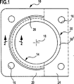
図1は、三層のシートメタル(図2参照)から成るガスケットプレート10を備えたシリンダヘッドガスケットを示しており、このガスケットプレートには少なくとも本質的に円形の燃焼室用開口14と、シリンダヘッド用ネジが貫通するためのネジ用開口16とがスタンプ成形されている。図1は一つの燃焼室開口のみを示しており、燃焼室開口の中心または軸線が参照番号18で示されている。
FIG. 1 shows a cylinder head gasket with a
ガスケットプレート10は、上側カバーシート20と、下側カバーシート22と、これらの間に配置された支持シート24とから構成される。燃焼室用開口14のシールまたは関連する燃焼室の燃焼気体の出口に対するシールは本質的に、二枚のカバーシート20および22におけるビード26および28によりもたらされる。これらビード26および28は、ガスケットプレート10の平面視において円形状であり、燃焼室用開口14に対して同心的に延びると共に、図示した実施形態においては支持シート24に向かう方向に突出する所謂完全ビードとして設計される。ビード26および28は、ガスケットプレート10に対して直角方向に平坦化されるという意味において、ガスケットが所定位置に挟持されたとき及びエンジンの作動中にスプリング弾性形態で変形可能とされるべきであり、このためカバーシート20および22はシート状のバネ鋼から成る。
The
エンジンの作動中に二つのビード26および28が過剰に変形されないように支持シート24上には本発明のストッパ30が形成される。ストッパ30は燃焼室用開口14の軸線18に対してビード26および28の径方向内側に配置されるが、これらビードの径方向外側にも配置されてもよいし、または各ビードの径方向内側と径方向外側との両側に配備されてもよい。これに加え、二つのビード26および28は厳密に対向して配置される必要が無いことは言うまでもなく、上記各ビードは少なくとも一つのストッパの近傍とされ且つ該ストッパの径方向外側もしくは径方向内側に配置されることのみが必要である。図1に示したようにストッパ30は、燃焼室用開口14を(支持シート24の平面視において)円形帯片として包囲し、図示した実施形態においてこの帯片は全体的に同一幅を有するが、このことは常に該当する必要はない。なぜなら、一定のシリンダヘッドガスケットの場合においては、燃焼室用開口の回りにおけるストッパの幅を公知の形態で変化させ、すなわち広幅の輪郭を提供することが推奨されるからである。
A
多気筒エンジンの場合、ガスケットプレート10は、数個の燃焼室用開口14と、各燃焼室用開口に対して少なくとも一つのビードおよび少なくとも一つのストッパから成るシール機構とを備える。図1および図2に示された実施形態においてはシール機構は二つのビードおよび一つのストッパから成る。
In the case of a multi-cylinder engine, the
図2に示した実施形態において全体を30として示した上記ストッパは、燃焼室用開口14に対して境界を為す支持シート24の円形領域24’と、支持シート24に固着された二つのストッパリング301および302とから成る。最も単純な場合、これらストッパリングは、例えばレーザ溶接により支持シート24に固着されたシートメタル製の打抜き形成リングである。
The stopper shown generally as 30 in the embodiment shown in FIG. 2 includes a
広く用いられる習用のシリンダヘッドガスケットの場合、支持シート24の厚みは約0.2mm〜約1.0mmであり、全体的に同一であるストッパリング301および302の厚みは約0.05mm〜約0.1mmであることから、図2は厚みの比率を正しく縮尺通りには示していない。さらに、燃焼室用開口14を包囲する領域において該領域よりも外側におけるよりも大きな厚みを円形状に有するように支持シート24を変形することにより、図2に示されたストッパと類似したストッパが生成されてもよいが、その場合ストッパ30は元の支持シート24の両主要表面を(例えば常に約0.05mm〜約0.1mmだけ)越えて突出するのが好ましい。いずれの場合にも、ストッパ30の全厚は、ガスケットが押圧されていないときにビード26および28が支持シート24に対して着座するがストッパ30とカバーシート20、22の少なくとも一方との間、好適には図2に示されたようにストッパ30とこれらの各カバーシートとの間に間隙が残るように寸法設定される。その結果、ビード26および28はエンジンの作動中に弾性的に平坦化されるが、完全に平坦には押圧されず、よって過剰には変形され得ないことが確実とされる。
If widely cylinder head gasket習用used, the thickness of the
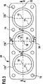
図1および図2は本発明のシリンダヘッドガスケットの端部領域のみを示すが、図3は三気筒エンジンに対するシリンダヘッドガスケットの支持シート24全体の平面図を示す。シリンダヘッドガスケットのガスケットプレート10は三つの燃焼室用開口14を備えている。ガスケットプレート10の平面に対して直角に延びると共に全ての燃焼室用開口14の軸線18を通るガスケットの長手中心面は参照番号32で示され、ガスケットの横手中心面は参照番号34で示されており、この横手中心面は長手中心面32に対して直角に延びると共に各端部燃焼室用開口14の軸線18から、すなわち各外側燃焼室用開口の軸線から等距離に位置する。
1 and 2 show only the end region of the cylinder head gasket of the present invention, while FIG. 3 shows a plan view of the entire cylinder head
本発明のシリンダヘッドガスケットは、燃焼室用開口に対するシール用ビードとこれらビードを一切の過剰変形から保護するストッパとを備える単一のシートメタル層のみを有する単層ガスケットともされ得ることから、簡素化のために図4A〜図4Eにおいては図示したシートメタル層の一方の側上のみにストッパを示す。但し、このシートメタル層は依然として支持シート24と表される。多気筒エンジンに対する本発明のガスケットの場合、種々の燃焼室用開口に対応するストッパはそれらの高さまたは厚みに関して異なる形態であることから、図3および図4A〜図4Eに示したストッパリングは図2と同様に1301、2301および3301と示される。但し、図4A〜図4Eの変更例において、上記ストッパリングは図示したシートメタル層(支持シート24)の両側上に配備されてもよいことは言うまでも無い。
Since the cylinder head gasket of the present invention can be a single-layer gasket having only a single sheet metal layer provided with a sealing bead for the opening for the combustion chamber and a stopper for protecting these beads from any excessive deformation, the cylinder head gasket is simple. 4A to 4E, a stopper is shown only on one side of the illustrated sheet metal layer. However, this sheet metal layer is still represented as the
図4Aは、ストッパの、より詳細には本発明の基本的着想に係るストッパリング1301、2301および3301の高さ変移設定を示している。これによれば、習用のガスケットと比較して、シリンダヘッド用ネジにより生成されてガスケットに作用する押圧力はガスケットの長手端部の領域においては小さいものとされ且つガスケットの横手中心面34に向かう方向においては大きくなることが意図されている。図4Aにおいて一点鎖線40で示したようにストッパリングの有効高さは横手中心面34からの距離が長くなるにつれて低くなる。よって端部ストッパリング1301および3301の形態は中空シリンダに対応し、支持シート24と対面する一方の端面はシリンダ軸線に対して直角に延びる平面を画成し、他方の端面はシリンダ軸線に対して所定角度で延びる平面を画成する。一方、ストッパリング2301の形態は中空シリンダに対応し、支持シート24と対面する一方の端面はシリンダ軸線に対して直角に延びる平面を画成するが、他方の端面は、互いに対して傾斜した二つの平面を画成し、これら二つの平面はシリンダ軸線に対して両者ともに同一角度を成し且つそれぞれが中空シリンダの半周に亘って壁部を限定する。
FIG. 4A shows the height transition setting of the stoppers, more particularly the stopper rings 130 1 , 230 1 and 330 1 according to the basic idea of the invention. According to this, as compared with the customary gasket, the pressing force generated by the cylinder head screw and acting on the gasket is small in the region of the longitudinal end portion of the gasket and is directed toward the
図4Bおよび図4Cは上記ストッパ、より正確にはストッパリング1301、2301および3301に関する本発明の形態を示しておらず、逆に図4Bは上記ストッパリングの公知の高さ変移設定を示している。これによればシリンダヘッド用ネジにより生成されてガスケットに作用する押圧力が各シリンダヘッド用ネジ(もしくは各ネジ用開口16)からの距離が長くなるにつれて小さくなることが考慮され、その場合に図4Bに示した高さ変移設定は図3に示したネジ用開口16の配置に対してのみ該当することは勿論である。また、図4Bに示した高さ変移設定は、局所的に且つキャビティに関して可変的に減少するエンジンブロックおよび/またはシリンダヘッドの構成要素剛性を考慮すべく独国特許第4142600号(DE-41 42 600-C2)と同一の手法によって変更されてもよい。図4Bに示したようにネジ用開口16からの距離が長くなるにつれて押圧力が減少するという状況のみの単純な考察の場合、上記ストッパ、より正確にはストッパリング1301、2301および3301の全ては図4Bにおいて同一の一点鎖線50により示したように同一の高さ変移を有し、すなわち全てのストッパリングは同一である。この場合、各ストッパリングについてその近傍ビードの保護に利用可能な有効高さは以下のように変化する(説明のために図3に示された角度αを参照すると、この角度は反時計回りにおいて、長手中心面32における0°から、横手中心面34における90°を経て、再び長手中心面32における180°、再び横手中心面34における270°から再び長手中心面32における360°まで変化する)。すなわち、ストッパリングの高さは、各ネジ用開口16の間における中心において即ちα=0°、α=90°、α=180°およびα=270°において最大である。一方、ストッパリングの高さは、各ネジ用開口16の近傍、すなわちα=約45°、α=約135°、α=約225°およびα=約315°において最小であり、これらの極値の間において上記ストッパリングの高さは連続的に増大したりまたは連続的に減少したりする。
4B and 4C do not show the form of the present invention with respect to the stoppers, more precisely the stopper rings 130 1 , 230 1 and 330 1 , conversely FIG. 4B shows a known height transition setting for the stopper rings. Show. According to this, it is considered that the pressing force generated by the cylinder head screw and acting on the gasket becomes smaller as the distance from each cylinder head screw (or each screw opening 16) becomes longer. Of course, the height transition setting shown in FIG. 4B only applies to the arrangement of the
また、図4Cは、本発明の基本的着想を考慮せずに、特に2001年4月5日におけるElringKlinger AG社の独国特許出願第10117178号(German Patent Application No. 101 17 178)のエンジンブロックの局所的に変化する熱膨張のみを考慮したストッパ、より正確にはストッパリングの高さ変移を示している。図4Cにおいて一点鎖線601、602および603で示したように、ストッパリング1301、2301および3301の高さ変移については、隣り合った二つの燃焼室間に配置された(すなわちα=0°およびα=180°における)エンジンブロックの領域はエンジンを作動温度まで加熱する間に他の領域よりも大きな程度まで膨張するという事実が考慮されている。この場合、ストッパリング1301および3301の高さ変移は同一であるが横手中心面34に対して鏡像である。したがって、ストッパリング1301の高さはα=0°±約20°の領域において低いがその他の場合には全て同一であり、同様のことがα=180°±約20°におけるストッパリング3301の高さに関して適用される。ストッパリング2301の高さはα=0°±約20°およびα=180°±約20°の領域で低く、その他の場合には全て同一である。
FIG. 4C also shows the engine block of German patent application No. 101 17 178 of ElringKlinger AG, in particular on April 5, 2001, without taking into account the basic idea of the present invention. It shows a stopper that takes into account only the locally changing thermal expansion, more precisely, the height transition of the stopper ring. As indicated by the alternate long and
図4Dは一点鎖線701、702および703により表された本発明のストッパリングの高さ変移設定を示しており、(他の図4A、図4B、図4Cおよび図4Eにおけるのと同様に)高さ変移を表す一点鎖線は全体的に横手中心面34に対する鏡像で延びている。図4Dに示した高さ変移は本発明の基本的着想を用いることに加え、シリンダヘッド用ネジにより生成されてガスケットに作用する押圧力がネジ用開口16からの距離が長くなるにつれて減少するという事実を考慮している。よって、図4Dに示した線701、702および703は、図4Bからの各線50と図4Aからの各線40とを重ね合わせて得られたものである。
Figure 4D shows the height displacement setting of the stopper ring of the present invention represented by the dashed line 70 1, 70 2 and 70 3, as in (other figures 4A, 4B, 4C and 4E D) The alternate long and short dash line representing the height transition extends as a mirror image with respect to the
図4Eにおいて一点鎖線801、802および803により示された高さ変移は、本発明の基本的着想を考慮することに加え、ネジ用開口16からの距離の増大による押圧力の減少、並びに、隣り合う燃焼室間の狭幅領域における熱膨張による押圧力の増加を考慮している。したがって、図4Eにおける線801、802および803に係る高さ変移は図4Cおよび図4Dから得られる。なぜなら、平均値は図4Dに従うストッパの高さの増加と図4Cに従うストッパ高さの減少とから形成されるからである。
In FIG. 4E, the height transitions indicated by the dashed
図4A〜図4Eはストッパの、より正確にはストッパリングの高さ変移、すなわち高低差を相当に誇張して示しており、上記高低差は百分の数ミリメートル程度の大きさであることを銘記されたい。全体的に同一の高さを有する同一のストッパリングを備えた習用のシリンダヘッドガスケットの場合にビードの保護に有効なストッパリング高さが例えば0.12mmであれば、本発明のガスケットの場合における最大ストッパリング高さは約0.12mmであり且つ最小ストッパリング高さは約0.08mmであり、すなわちストッパリング高さの変化の範囲は約0.04mmである。この場合、言及された公知のガスケットと比較すると本ガスケットのストッパ高さは横手中心面の領域においてほぼ同一であるがガスケットの長手端部に向かう方向において低くせしめられる。 4A to 4E show the stopper, more precisely, the height shift of the stopper ring, that is, the height difference is considerably exaggerated. The height difference is about a few hundredths of a millimeter. I want to be noted. In the case of a conventional cylinder head gasket having the same stopper ring having the same overall height, if the stopper ring height effective for bead protection is 0.12 mm, for example, in the case of the gasket of the present invention. The maximum stopper ring height is about 0.12 mm and the minimum stopper ring height is about 0.08 mm, that is, the range of change of the stopper ring height is about 0.04 mm. In this case, the stopper height of the gasket is substantially the same in the region of the transverse center plane, but lower in the direction toward the longitudinal end of the gasket as compared to the known gasket mentioned.
なお、本発明により達成され得る利点に対して重要なのは絶対的なストッパ高さでも支持シートに取付けられるストッパの高さでもなく、本発明に従い変更される有効ストッパ高さである。よって、支持シートに対して全体的に等しい高さの同一のストッパリングが取付けられて、支持シートが例えばスタンプ成形によりストッパリングの領域において本発明の高さ変移を備える場合も含まれる。 It is to be noted that what is important to the advantages that can be achieved by the present invention is not the absolute stopper height or the height of the stopper attached to the support sheet, but the effective stopper height that is changed according to the present invention. Therefore, the case where the same stopper ring having the same overall height is attached to the support sheet, and the support sheet is provided with the height transition of the present invention in the region of the stopper ring, for example, by stamping.
Claims (8)
上記プレートは少なくとも一枚のシートメタル層を有し、
上記内燃機関は、二つの端部シリンダおよび少なくとも一つの中間シリンダを備える少なくとも一列のシリンダと、エンジンブロックと、これらシリンダの燃焼室を覆うシリンダヘッドとを有し、
当該シリンダヘッドガスケットは、シリンダヘッド用ネジにより上記シリンダヘッドと上記エンジンブロックとの間に挟持可能であり、
上記ガスケットプレートは、ネジ用開口および流体用開口と、各燃焼室に対する燃焼室用開口とを備え、且つ、
上記少なくとも一枚のシートメタル層は各燃焼室用開口に対し該開口を包囲する少なくとも一つのシール用ビードを有し、
上記ガスケットプレートの平面に対して直角な方向における上記ビードの変形は、少なくとも一つのシール用ビードと少なくとも一つの変形制限体とを有するシール機構が各燃焼室用開口に対して協働するように、上記ビードと同心的に延びる上記ガスケットプレートの少なくとも一つの変形制限体により制限される、シリンダヘッドガスケットにおいて、
シリンダヘッドガスケットを所定位置に挟持した状態にある内燃機関の作動中において上記シール機構に作用する押圧力を更に均一とするために、
a)所定位置に挟持されたシリンダヘッドガスケットにより内燃機関の作動温度において変形制限体に作用する圧力が上記変形制限体の円周に沿ってほぼ均一となるように、上記変形制限体はその円周に沿って上記内燃機関が作動温度となることにより予測されるエンジンブロックおよび/またはシリンダヘッドの局所的に変化する熱膨張に応じた高さ変移を有し、且つ
b)上記ビードの変形を制限するために利用可能であって上記ガスケットプレートの平面に対して直角に測定された各変形制限体の有効高さをその円周に亘って平均した高さ平均値について、上記各端部シリンダに対応する上記変形制限体の高さ平均値が中間シリンダに対応する少なくとも一つの他の変形制限体の高さ平均値よりも小さいことを特徴とするシリンダヘッドガスケット。A cylinder head gasket with a gasket plate for an internal combustion engine,
The plate has at least one sheet metal layer,
The internal combustion engine includes at least one row of cylinders including two end cylinders and at least one intermediate cylinder, an engine block, and a cylinder head that covers the combustion chambers of these cylinders.
The cylinder head gasket can be sandwiched between the cylinder head and the engine block by a cylinder head screw,
The gasket plate includes a screw opening and a fluid opening, and a combustion chamber opening for each combustion chamber, and
The at least one sheet metal layer has at least one sealing bead surrounding each opening for each combustion chamber opening;
The deformation of the bead in a direction perpendicular to the plane of the gasket plate is such that a sealing mechanism having at least one sealing bead and at least one deformation limiter cooperates with each combustion chamber opening. , Ru is limited by at least one deformation restriction element of the gasket plate extending the bead concentrically, in shea cylinder head gasket,
In order to make the pressing force acting on the seal mechanism more uniform during operation of the internal combustion engine in a state where the cylinder head gasket is held in place,
a) The deformation restricting body has a circular shape so that the pressure acting on the deformation restricting body at the operating temperature of the internal combustion engine is substantially uniform along the circumference of the deformation restricting body by the cylinder head gasket held in place. Having a height transition in response to locally changing thermal expansion of the engine block and / or cylinder head predicted by the internal combustion engine being at operating temperature along the circumference, and b) deforming the bead For each of the end cylinders, a height average value that can be used for limiting and averages the effective height of each deformation limiting body measured at right angles to the plane of the gasket plate over its circumference. A cylinder head characterized in that an average height value of the deformation limiting body corresponding to the above is smaller than an average height value of at least one other deformation limiting body corresponding to the intermediate cylinder gasket.
上記各変形制限体の高さ平均値は全て、上記横手中心面から各変形制限体に対応する燃焼室用開口の中心までの距離が大きくなるにつれて小さくなることを特徴とするシリンダヘッドガスケット。The cylinder head gasket includes a transverse center plane extending at right angles to the plane of the gasket plate, and the center of the combustion chamber opening corresponding to each of the end cylinders has the same distance from the transverse center plane. In the cylinder head gasket according to any one of claims 3,
The cylinder head gasket according to claim 1, wherein all of the height average values of the respective deformation restriction bodies are reduced as the distance from the lateral center plane to the center of the combustion chamber opening corresponding to each deformation restriction body is increased.
上記変形制限体は他方のシートメタル層上に配備されることを特徴とするシリンダヘッドガスケット。The cylinder head gasket according to any one of claims 1 to 5, wherein a gasket plate of the cylinder head gasket has at least two sheet metal layers, and one of the layers includes the sealing bead.
The cylinder head gasket according to claim 1, wherein the deformation restriction body is disposed on the other sheet metal layer.
上記変形制限体の領域において上記シートメタル層は請求項1〜7のいずれか1項において定義された高さ変移を有することを特徴とするシリンダヘッドガスケット。In the cylinder head gasket in which the deformation limiting body is attached to the sheet metal layer,
The cylinder head gasket according to any one of claims 1 to 7, wherein the sheet metal layer has a height transition as defined in any one of claims 1 to 7.
Applications Claiming Priority (2)
| Application Number | Priority Date | Filing Date | Title |
|---|---|---|---|
| DE10224856A DE10224856B4 (en) | 2002-06-05 | 2002-06-05 | Cylinder head gasket |
| PCT/EP2003/005616 WO2003104687A1 (en) | 2002-06-05 | 2003-05-28 | Cylinder-head gasket |
Publications (2)
| Publication Number | Publication Date |
|---|---|
| JP2005520106A JP2005520106A (en) | 2005-07-07 |
| JP3971423B2 true JP3971423B2 (en) | 2007-09-05 |
Family
ID=29718842
Family Applications (1)
| Application Number | Title | Priority Date | Filing Date |
|---|---|---|---|
| JP2004511722A Expired - Fee Related JP3971423B2 (en) | 2002-06-05 | 2003-05-28 | Cylinder head gasket |
Country Status (5)
| Country | Link |
|---|---|
| EP (1) | EP1404993B1 (en) |
| JP (1) | JP3971423B2 (en) |
| KR (1) | KR100714173B1 (en) |
| DE (2) | DE10224856B4 (en) |
| WO (1) | WO2003104687A1 (en) |
Families Citing this family (3)
| Publication number | Priority date | Publication date | Assignee | Title |
|---|---|---|---|---|
| DE102004026395A1 (en) | 2004-05-29 | 2005-12-22 | Elringklinger Ag | Cylinder head gasket |
| DE102012100919A1 (en) * | 2012-02-03 | 2013-08-08 | Elringklinger Ag | Metallic flat gasket |
| US11519505B2 (en) | 2021-03-24 | 2022-12-06 | Federal-Mogul Motorparts Llc | Multi-layer steel gasket |
Family Cites Families (9)
| Publication number | Priority date | Publication date | Assignee | Title |
|---|---|---|---|---|
| JPH01208554A (en) * | 1988-02-15 | 1989-08-22 | Kuniaki Numaya | Metal gasket |
| JP2989282B2 (en) * | 1991-01-09 | 1999-12-13 | 日本ガスケット株式会社 | Metal gasket |
| DE4219709C2 (en) * | 1992-06-16 | 2001-07-12 | Reinz Dichtungs Gmbh | Metallic flat gasket |
| US5618049A (en) * | 1993-06-04 | 1997-04-08 | Japan Metal Gasket Co., Ltd. | Metallic gasket |
| DE19513360C1 (en) * | 1995-04-08 | 1996-06-27 | Elringklinger Gmbh | Metallic cylinder head gasket for IC engine |
| DE59604933D1 (en) * | 1995-04-08 | 2000-05-18 | Elringklinger Gmbh | Metallic cylinder head gasket |
| DE19548573C1 (en) * | 1995-12-23 | 1996-12-19 | Elringklinger Gmbh | Cylinder head seal for IC engine - has plastically deformable sealing layers in area of spring travel limiters between seal plates |
| DE10005455C2 (en) * | 2000-02-08 | 2003-10-16 | Reinz Dichtungs Gmbh & Co Kg | Metallic flat gasket |
| JP2002054740A (en) * | 2000-08-07 | 2002-02-20 | Ishikawa Gasket Co Ltd | Head gasket for multi-cylinder |
-
2002
- 2002-06-05 DE DE10224856A patent/DE10224856B4/en not_active Withdrawn - After Issue
-
2003
- 2003-05-28 DE DE50300322T patent/DE50300322D1/en not_active Revoked
- 2003-05-28 JP JP2004511722A patent/JP3971423B2/en not_active Expired - Fee Related
- 2003-05-28 EP EP03730136A patent/EP1404993B1/en not_active Revoked
- 2003-05-28 KR KR1020047006100A patent/KR100714173B1/en not_active IP Right Cessation
- 2003-05-28 WO PCT/EP2003/005616 patent/WO2003104687A1/en active IP Right Grant
Also Published As
| Publication number | Publication date |
|---|---|
| DE50300322D1 (en) | 2005-03-31 |
| KR20040055794A (en) | 2004-06-26 |
| EP1404993A1 (en) | 2004-04-07 |
| EP1404993B1 (en) | 2005-02-23 |
| KR100714173B1 (en) | 2007-05-02 |
| WO2003104687A1 (en) | 2003-12-18 |
| JP2005520106A (en) | 2005-07-07 |
| DE10224856A1 (en) | 2004-01-08 |
| DE10224856B4 (en) | 2004-05-27 |
Similar Documents
| Publication | Publication Date | Title |
|---|---|---|
| US5286039A (en) | Metal gasket | |
| US6076833A (en) | Metal gasket | |
| US20070013145A1 (en) | Cylinder head gasket | |
| EP1128099A2 (en) | Cylinder head gasket | |
| US7669859B2 (en) | Cylinder head gasket | |
| EP2971874B1 (en) | Small elastic sealing feature inside of main combustion sealing embossment | |
| US6164662A (en) | Metal gasket | |
| US6478307B2 (en) | Metal gasket | |
| US7806416B2 (en) | Cylinder head gasket | |
| US7806415B2 (en) | Cylinder head gasket | |
| JP3971423B2 (en) | Cylinder head gasket | |
| US20060163817A1 (en) | Cylinder head gasket | |
| EP1143174A2 (en) | Laminated gasket | |
| JP4541400B2 (en) | Metal gasket | |
| US20060261561A1 (en) | Flat gasket, in particular cylinder-head gasket | |
| JP4330897B2 (en) | Metal gasket | |
| JP3946217B2 (en) | Metal gasket | |
| US7014194B2 (en) | Cylinder head gasket | |
| EP1111277A2 (en) | Metal Gasket | |
| JP2527102Y2 (en) | Metal gasket | |
| US20180266559A1 (en) | Flat gasket and sealing assembly containing a flat gasket | |
| JP4640342B2 (en) | Seal structure and gasket for internal combustion engine | |
| JP4508667B2 (en) | Metal gasket for cylinder head | |
| JP3142199B2 (en) | Metal gasket | |
| JP2002323135A (en) | Single-layer metal gasket |
Legal Events
| Date | Code | Title | Description |
|---|---|---|---|
| A131 | Notification of reasons for refusal |
Free format text: JAPANESE INTERMEDIATE CODE: A131 Effective date: 20060829 |
|
| A601 | Written request for extension of time |
Free format text: JAPANESE INTERMEDIATE CODE: A601 Effective date: 20061128 |
|
| A602 | Written permission of extension of time |
Free format text: JAPANESE INTERMEDIATE CODE: A602 Effective date: 20061206 |
|
| A521 | Written amendment |
Free format text: JAPANESE INTERMEDIATE CODE: A523 Effective date: 20070228 |
|
| TRDD | Decision of grant or rejection written | ||
| A01 | Written decision to grant a patent or to grant a registration (utility model) |
Free format text: JAPANESE INTERMEDIATE CODE: A01 Effective date: 20070508 |
|
| A61 | First payment of annual fees (during grant procedure) |
Free format text: JAPANESE INTERMEDIATE CODE: A61 Effective date: 20070607 |
|
| R150 | Certificate of patent or registration of utility model |
Free format text: JAPANESE INTERMEDIATE CODE: R150 |
|
| FPAY | Renewal fee payment (event date is renewal date of database) |
Free format text: PAYMENT UNTIL: 20110615 Year of fee payment: 4 |
|
| LAPS | Cancellation because of no payment of annual fees |