JP3971376B2 - Container for a composition comprising two or more components - Google Patents
Container for a composition comprising two or more components Download PDFInfo
- Publication number
- JP3971376B2 JP3971376B2 JP2003503516A JP2003503516A JP3971376B2 JP 3971376 B2 JP3971376 B2 JP 3971376B2 JP 2003503516 A JP2003503516 A JP 2003503516A JP 2003503516 A JP2003503516 A JP 2003503516A JP 3971376 B2 JP3971376 B2 JP 3971376B2
- Authority
- JP
- Japan
- Prior art keywords
- container
- housing
- components
- component
- chamber
- Prior art date
- Legal status (The legal status is an assumption and is not a legal conclusion. Google has not performed a legal analysis and makes no representation as to the accuracy of the status listed.)
- Expired - Fee Related
Links
- 239000000203 mixture Substances 0.000 title claims abstract description 44
- 238000002156 mixing Methods 0.000 abstract description 18
- 239000000853 adhesive Substances 0.000 description 12
- 230000001070 adhesive effect Effects 0.000 description 12
- 239000011888 foil Substances 0.000 description 8
- 239000000463 material Substances 0.000 description 7
- 239000004033 plastic Substances 0.000 description 7
- 229920003023 plastic Polymers 0.000 description 7
- -1 polypropylene Polymers 0.000 description 6
- 239000011248 coating agent Substances 0.000 description 5
- 238000000576 coating method Methods 0.000 description 5
- 239000004615 ingredient Substances 0.000 description 5
- 229910052751 metal Inorganic materials 0.000 description 5
- 239000002184 metal Substances 0.000 description 5
- 229920006332 epoxy adhesive Polymers 0.000 description 4
- 238000004519 manufacturing process Methods 0.000 description 4
- 229910052782 aluminium Inorganic materials 0.000 description 3
- XAGFODPZIPBFFR-UHFFFAOYSA-N aluminium Chemical compound [Al] XAGFODPZIPBFFR-UHFFFAOYSA-N 0.000 description 3
- 239000003795 chemical substances by application Substances 0.000 description 3
- 239000000835 fiber Substances 0.000 description 3
- 238000000465 moulding Methods 0.000 description 3
- 229920000642 polymer Polymers 0.000 description 3
- 238000003860 storage Methods 0.000 description 3
- 239000004698 Polyethylene Substances 0.000 description 2
- 239000004743 Polypropylene Substances 0.000 description 2
- 230000002411 adverse Effects 0.000 description 2
- 239000004568 cement Substances 0.000 description 2
- 238000006243 chemical reaction Methods 0.000 description 2
- 230000004927 fusion Effects 0.000 description 2
- JRZJOMJEPLMPRA-UHFFFAOYSA-N olefin Natural products CCCCCCCC=C JRZJOMJEPLMPRA-UHFFFAOYSA-N 0.000 description 2
- 229920000573 polyethylene Polymers 0.000 description 2
- 229920001155 polypropylene Polymers 0.000 description 2
- 238000007792 addition Methods 0.000 description 1
- 230000004888 barrier function Effects 0.000 description 1
- 230000015572 biosynthetic process Effects 0.000 description 1
- 239000002981 blocking agent Substances 0.000 description 1
- 239000003479 dental cement Substances 0.000 description 1
- 238000006073 displacement reaction Methods 0.000 description 1
- 244000144992 flock Species 0.000 description 1
- 239000012530 fluid Substances 0.000 description 1
- 238000009472 formulation Methods 0.000 description 1
- 230000001771 impaired effect Effects 0.000 description 1
- 208000015181 infectious disease Diseases 0.000 description 1
- 238000005304 joining Methods 0.000 description 1
- 239000007788 liquid Substances 0.000 description 1
- 239000012528 membrane Substances 0.000 description 1
- 238000000034 method Methods 0.000 description 1
- 238000004806 packaging method and process Methods 0.000 description 1
- 238000012856 packing Methods 0.000 description 1
- 239000008188 pellet Substances 0.000 description 1
- 230000002093 peripheral effect Effects 0.000 description 1
- 239000000843 powder Substances 0.000 description 1
- 238000000926 separation method Methods 0.000 description 1
- 239000007787 solid Substances 0.000 description 1
Images


Classifications
-
- B—PERFORMING OPERATIONS; TRANSPORTING
- B65—CONVEYING; PACKING; STORING; HANDLING THIN OR FILAMENTARY MATERIAL
- B65D—CONTAINERS FOR STORAGE OR TRANSPORT OF ARTICLES OR MATERIALS, e.g. BAGS, BARRELS, BOTTLES, BOXES, CANS, CARTONS, CRATES, DRUMS, JARS, TANKS, HOPPERS, FORWARDING CONTAINERS; ACCESSORIES, CLOSURES, OR FITTINGS THEREFOR; PACKAGING ELEMENTS; PACKAGES
- B65D81/00—Containers, packaging elements, or packages, for contents presenting particular transport or storage problems, or adapted to be used for non-packaging purposes after removal of contents
- B65D81/32—Containers, packaging elements, or packages, for contents presenting particular transport or storage problems, or adapted to be used for non-packaging purposes after removal of contents for packaging two or more different materials which must be maintained separate prior to use in admixture
- B65D81/3216—Rigid containers disposed one within the other
- B65D81/3222—Rigid containers disposed one within the other with additional means facilitating admixture
-
- B—PERFORMING OPERATIONS; TRANSPORTING
- B65—CONVEYING; PACKING; STORING; HANDLING THIN OR FILAMENTARY MATERIAL
- B65D—CONTAINERS FOR STORAGE OR TRANSPORT OF ARTICLES OR MATERIALS, e.g. BAGS, BARRELS, BOTTLES, BOXES, CANS, CARTONS, CRATES, DRUMS, JARS, TANKS, HOPPERS, FORWARDING CONTAINERS; ACCESSORIES, CLOSURES, OR FITTINGS THEREFOR; PACKAGING ELEMENTS; PACKAGES
- B65D85/00—Containers, packaging elements or packages, specially adapted for particular articles or materials
- B65D85/70—Containers, packaging elements or packages, specially adapted for particular articles or materials for materials not otherwise provided for
Abstract
Description
本発明は、2以上の成分から製作される組成物のための保管および配合用容器に関する。容器は、一定量の組成物の使用が必要とされるまで、互いに離した状態の少なくとも2種類の成分を保管する。 The present invention relates to storage and formulation containers for compositions made from two or more components. The container stores at least two components separated from each other until a certain amount of the composition is required to be used.
有用な組成物には、一定量の組成物が使用するために必要とされる直前まで、通常混合されることのない2種類の成分から構成されているものが多い。たとえば、エポキシ系接着剤の成分は、互いに接触するとすぐに、化学反応が始まり、最終的には混合された組成物を固くなった塊になるために、互いに離して保管される。そのため、エポキシ系接着剤は、接着剤の成分を最初は互いに分離した状態に保つ2つのコンパートメントまたは2つの分離容器を含むパッケージで広く市販されている。 Useful compositions often consist of two components that are not normally mixed until just before a certain amount of the composition is needed for use. For example, the components of the epoxy adhesive are stored away from each other as soon as they come into contact with each other to initiate a chemical reaction and eventually harden the mixed composition. For this reason, epoxy adhesives are widely marketed in packages that contain two compartments or two separation containers that initially keep the components of the adhesive separated from each other.
複数の成分を含む組成物用のパッケージの中には比較的大きく、異なる時に、複数の用途で用いるのに十分な量の成分を含むものがある。たとえば、エポキシ系接着剤は、缶、瓶および搾り出すことが可能なチューブなどの大量用容器で市販されている。接着剤の一方の成分(「A剤」と呼ぶことが多い)は1つの大量用容器で供給され、他方の成分(「B剤」と呼ぶことが多い)は形状および構成が第1の容器と通常は同じである別の容器で供給される。成分を梱包する費用が比較的廉価であるために、このような大量用容器が普及している。 Some packages for compositions containing multiple components are relatively large and, at different times, contain sufficient amounts of components for use in multiple applications. For example, epoxy adhesives are commercially available in high volume containers such as cans, bottles and squeezable tubes. One component of the adhesive (often referred to as “agent A”) is supplied in one bulk container and the other component (often referred to as “agent B”) is the first container in shape and configuration. And is usually supplied in a separate container that is the same. Such high volume containers are popular because of the relatively low cost of packing the ingredients.
大量用容器に保管されている成分から接着剤を調製するために、容器から取り出して各成分の量が測定され、混合場所に移し変えられる。混合場所は、混合ウェル、混合パッドまたは第3の容器であってもよい。次に、使用者は、成分を混合し、へら、ブラシまたは他の適切な道具を用いて混合した成分を塗布場所に移し変える。 To prepare the adhesive from the components stored in the bulk container, the amount of each component is measured from the container and transferred to the mixing location. The mixing location may be a mixing well, a mixing pad or a third container. The user then mixes the ingredients and uses a spatula, brush or other suitable tool to transfer the mixed ingredients to the application site.
しかし、2つの大量用容器で複数の成分からなる組成物を供給する手法は、全面的に満足するものではない。たとえば、使用者が正確な比で大量用容器から成分を取り出すことができない場合には、結果として生じる組成物の特性を著しく損なう可能性がある。さらに、容器に残っている成分の部分は、一旦容器が開封されると空気に曝されることによって、一定の期間にわたって悪影響を受ける可能性がある。使用者はまた、1回の使用後、混合パッド、混合ウェルまたは他の混合容器を処分するか、または次の使用に向けて同容器を洗浄する作業を行うことを強いられる。さらに、他方の成分を汚染したり、他方の成分の性質に悪影響を及ぼす化学反応を起こしたりする恐れがあるため、一方の容器からの成分が、残っている大量用容器に不注意から移らないように細心の注意を払わなければならない。 However, the method of supplying a composition comprising a plurality of components in two large-volume containers is not completely satisfactory. For example, if the user is unable to remove components from the bulk container at the exact ratio, the resulting composition properties can be significantly impaired. Furthermore, the portion of the component remaining in the container can be adversely affected over a period of time by being exposed to air once the container is opened. The user is also forced to dispose of the mixing pad, mixing well or other mixing container after a single use or to clean the container for subsequent use. In addition, components from one container cannot be inadvertently transferred to the remaining bulk container because it can contaminate the other component or cause a chemical reaction that adversely affects the properties of the other component. So be careful.
近年、最初は互いに離した状態の2種類の成分から構成される組成物のための「使い捨て」容器への関心が高まっている。このような容器は一般に、混合前に、各成分の個別の量を計量する必要性を回避する。これらの容器はまた、混合時に、成分が結果として生じる組成物の所望の比であることを確実にするのに役立つ。さらに、成分が容器内で混合される場合に、混合ウェル、混合パッド、混合容器または他のタイプの混合構造物の必要性が回避される。 In recent years, there has been increased interest in “disposable” containers for compositions composed of two components that are initially separated from each other. Such containers generally avoid the need to weigh individual amounts of each component prior to mixing. These containers also help to ensure that the ingredients are in the desired ratio of the resulting composition when mixed. Furthermore, the need for mixing wells, mixing pads, mixing containers or other types of mixing structures is avoided when the components are mixed in the container.
最初は互いに離した状態の2種類以上の成分から構成される組成物はまた、歯列矯正をはじめとする医療および歯科の分野で広く用いられている。たとえば、歯科で用いられるさまざまな接着剤およびセメントは、使用直前まで混合されない2種類の成分から構成される。2成分歯科組成物の例としては、いずれもスリーエム・カンパニー(3M Company)製であるリライエックスARC(RelyX ARC)歯科用セメントおよびF2000プライマー/接着剤が挙げられる。 Compositions composed of two or more components that are initially separated from each other are also widely used in the medical and dental fields, including orthodontics. For example, various adhesives and cements used in dentistry are composed of two components that are not mixed until just before use. Examples of two-component dental compositions include RelyX ARC dental cement and F2000 primer / adhesive, both manufactured by 3M Company.
1人の患者に使用した後、容器をアプリケータと共に処分することができるため、複数の成分からなる組成物用の使い捨ての容器は、医療組成物および歯科組成物の場合には特に好都合である。このように、患者から患者に感染症を移す危険性が実質的に低減される。比較的ごく少量の組成物が任意の時点において必要とされることが多く、より少ない「単回投与量」または「使い捨て」容器は、必要に応じて組成物の混合したてのバッチが利用可能であることを保証するのに役立つ。 Disposable containers for multi-component compositions are particularly advantageous in the case of medical and dental compositions because the container can be disposed of with the applicator after use with a single patient. . In this way, the risk of transferring an infection from patient to patient is substantially reduced. A relatively small amount of the composition is often required at any point in time, and smaller “single dose” or “disposable” containers are available for freshly mixed batches of the composition as needed Help to ensure that.
複数の成分からなる組成物用の成分の分離保管に特に適した容器の例は、たとえば、米国特許第5,735,437号明細書および米国特許第5,743,736号明細書に記載されている。しかし、容器の製作費用が低減されるように、最新技術を改良する必要が依然としてある。このような容器は使いやすく、保管される成分の貯蔵寿命が十分であるという確実な保証もさらに提供するものであることが好ましい。 Examples of containers that are particularly suitable for separate storage of components for a multi-component composition are described, for example, in US Pat. No. 5,735,437 and US Pat. No. 5,743,736. ing. However, there is still a need to improve the state of the art so that the cost of manufacturing the container is reduced. Such containers are preferably easy to use and additionally provide a reliable guarantee that the shelf life of the components being stored is sufficient.
本発明は、2以上の成分から構成される組成物用の改良した容器に関する。容器は、歯科の分野で見られるような使い捨ての用途に特に適している。混合のために個別の位置に成分を移し変える必要性が不要となるように、成分の保管に加えて、成分の混合および調合に容器を用いることができる。 The present invention relates to an improved container for a composition composed of two or more components. The container is particularly suitable for disposable applications such as those found in the dental field. In addition to component storage, containers can be used to mix and formulate components so that the need to transfer components to separate locations for mixing is eliminated.
さらに詳細には、本発明は、一態様において、2以上の成分から構成される組成物用の容器に関する。容器は、チャンバを有する外部筐体と、コンパートメントを有する内部筐体と、を具備している。内部筐体は、脆性壁部と、脆性壁部から離隔された第1の開口部と、を具備している。カバーは、第1の開口部にわたって延在している。第1の成分はチャンバに収容され、第2の成分はコンパートメントに収容される。内部筐体は外部筐体に収容される。脆性壁部が破壊すると、第1の成分が第2の成分と接触する。 More particularly, the present invention in one aspect relates to a container for a composition composed of two or more components. The container includes an outer casing having a chamber and an inner casing having a compartment. The internal housing includes a brittle wall portion and a first opening portion separated from the brittle wall portion. The cover extends over the first opening. The first component is contained in the chamber and the second component is contained in the compartment. The inner casing is accommodated in the outer casing. When the brittle wall breaks, the first component contacts the second component.
本発明はまた、別の態様において、2以上の成分から構成される組成物用の容器に関する。この態様では、容器は、チャンバおよび穿刺具を有する外部筐体を具備している。容器はまた、外部筐体のチャンバに摺動可能であるように収容される内部筐体も具備している。内部筐体は、脆性壁部を備えたコンパートメントを有する。第1の成分はチャンバに収容され、第2の成分はコンパートメントに収容される。内部筐体は、脆性壁部が穿刺具から離隔された第1の位置から、第1の成分および第2の成分が互いに接するように、脆性壁部が穿刺具によって破壊された第2の位置まで摺動可能である。 The invention also relates, in another aspect, to a container for a composition composed of two or more components. In this embodiment, the container includes an outer housing having a chamber and a puncture device. The container also includes an inner housing that is slidably received in a chamber of the outer housing. The inner housing has a compartment with a brittle wall. The first component is contained in the chamber and the second component is contained in the compartment. The internal housing has a second position where the brittle wall portion is broken by the puncture tool so that the first component and the second component are in contact with each other from the first position where the brittle wall portion is separated from the puncture tool. Is slidable.
本発明による容器は、所望であれば外部筐体とは個別に内部筐体を製作することができるという利点がある。その結果、脆性壁部を設置し、カバーを連結し、2つの成分を容器に加える製作ステップが容易になる。任意に、内部筐体および外部筐体はいずれも、プラスチック材料から廉価に製作されることができ、カバーおよび/または脆性壁部は、熱融着によって所定の位置に固定される金属箔またはプラスチックフィルムを用いて作製されることができる。その結果、容器の費用は比較的廉価である。 The container according to the invention has the advantage that the internal housing can be produced separately from the external housing if desired. As a result, the manufacturing steps of installing the brittle wall, connecting the cover, and adding the two components to the container are facilitated. Optionally, both the inner and outer housings can be made inexpensively from a plastic material, and the cover and / or the brittle wall are fixed in place by thermal fusion metal foil or plastic It can be made using a film. As a result, the cost of the container is relatively low.
本発明のさらなる詳細は、特許請求の範囲の特徴において定義される。 Further details of the invention are defined in the features of the claims.
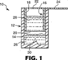
2以上の成分から構成される組成物用の容器が図1〜図3に示されており、参照符号10によって概ね表される。容器10は、チャンバ14を有する外部筐体12を具備している。図面に示されている向きでは、容器10は、下部閉鎖端部および上部開口部を有し、全体として円筒形の構造を供している。
A container for a composition composed of two or more components is shown in FIGS. 1-3 and is generally represented by
図1および図3に示されているように、容器10はまた、コンパートメント18を有する内部筐体16を具備している。内部筐体16は、上部開口部、すなわち(「第1の開口部」)を備えた全体として円筒形の構造を有する本体を具備している。内部筐体16はまた、本体に連結され、かつ上部開口部から離隔された脆性壁部を具備している。内部筐体16の外径は、外部筐体12の内径より少しだけ小さいことが好ましいが、内部筐体16が外部筐体12の底部への移動時にチャンバ14から空気が抜けやすい程度に十分に小さい。
As shown in FIGS. 1 and 3, the
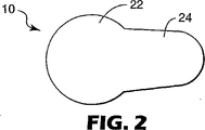
容器10は、図2にも示されているカバー22を具備している。カバー22は、内部筐体16の上部、すなわち第1の開口部のほか、外部筐体12の上部開口部(すなわち「第2の開口部」)にわたって延在する。カバー22は、外部筐体12の半径にほぼ等しい半径の第1の円形部分のほか、第1の部分から横方向の外側に延在している第2の部分を具備している。第2の部分は、外部筐体12を越えて延在し、必要であれば、カバー22を把持するためのタブ24を提供する。
The
複数の成分からなる組成物の第1の成分26は、チャンバ14に収容される。図面に示されている実施形態において、第1の成分26は、内部筐体16の脆性壁部20の下に配置される。複数の成分からなる組成物の第2の成分28は、コンパートメント18に収容される。
The
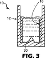
内部筐体16は、図1に示されている第1の位置から図3に示されている第2の位置まで外部筐体12の中で摺動可能である。内部筐体16の第1の位置において、脆性壁部20は、外部筐体12の下端壁から上方に延びている穿刺具30から離隔される。内部筐体16が図3に示されている第2の位置まで移動されるとき、穿刺具30は脆性壁部20を破るため、第1の成分26および第2の成分28が互いに接触することができる。
The
使用時に、カバー22は取り外され、好ましくはアプリケータを用いて、内部筐体16を下方向に移動する。アプリケータは、内部筐体16の上方の今は丸見えの端部に対して配置され、使用者は外部筐体12を保持するか、または適切な面に外部筐体12を載せることが好ましい。(たとえば、脆性壁部20の上側に対してアプリケータを配置するのではなく、)内部筐体16の上端に対してアプリケータを配置することによって、アプリケータの先端が穿刺具30の上端に接触しないようにして、第1の成分26および第2の成分28が一つになるときまで、第2の成分28と接触しないようにする。
In use, the
適切なアプリケータの例としては、フロリダ州オーランドのマイクロブラッシュ・コーポレーション(Microbrush Corporation(Orland,FL))から「マイクロブラシ」(MICROBRUSH)というブランド名のアプリケータが挙げられる。「マイクロブラシ」(MICROBRUSH)というブランド名のアプリケータは、複数の比較的短いフロックファイバを備えた先端を有する。弱な壁部20に穴が開けられた後、成分26、28の混合を促進するほか、フロックファイバはまた、歯の形成窩洞面などの塗布場所にわたって、結果として生じる混合組成物を塗布するのに役立つ。
An example of a suitable applicator is the applicator under the brand name “MICROBRUSH” from Microbrush Corporation (Orlando, FL), Orlando, Florida. The applicator under the brand name “MICROBRUSH” has a tip with a plurality of relatively short floc fibers. In addition to facilitating mixing of the
外部筐体12は、比較的長い期間、第1の成分26を入れておくのに適している任意の材料から構成されることができる。結果として生じる混合組成物が接着剤である場合には、(たとえば、)ポリプロピレン、ポリエチレン、環状オレフィンコなどのポリマーから外部筐体12を構成することができる。外部筐体12を通じた気体分子の移動を減少させるために、このようなプラスチックは、必要に応じて(たとえば、金属コーティングまたはポリマーコーティングによって)コーティングが可能である。さらに、このようなプラスチックは、必要であれば、保管される成分の性質に応じて、光遮断剤を含むことが可能である。
The
同様に、内部筐体16はまた、ポリプロピレン、ポリエチレン、環状オレフィンコなどのポリマーなどのプラスチック材料から構成されることができる。任意に、内部筐体16のプラスチック材料には、気体分子の移動を阻止するためにコーティングが施される。付加的なオプションとして、プラスチック材料は、透明、半透明または白色などの比較的明るい色を付けることができる。場合によっては、黒い外部筐体12および白い内部筐体16を設けることが望ましいことがある。このような構成であれば、使用者は、(この場合には黒い)穿刺具30が白い脆性壁部20を貫通したことを容易に観察し、目で確認することができるためである。
Similarly, the
必要に応じて、単独の一体成形構成要素として内部筐体16を成形し、脆性壁部が比較的薄く、壊れやすいように、成形用金型を配置することによって、脆性壁部20を構成することができる。別のオプションとして、円筒本体に膜を固定することによって、脆性壁部20を形成してもよい。
If necessary, the
適切な脆性膜の例としては、厚さ0.05mmのアルミニウム箔などの金属箔が挙げられる。任意に、箔は、ヒートシール接着剤などの接着剤によって内部筐体16の円筒本体の下端に固定される。熱融コーティングを有する適切な金属膜は、ユニパック・コーポレーション(Unipac Corporation)から「セーフガード」(SAFE−GARD)というブランド名の材料のNO.602である。
Examples of suitable brittle films include metal foils such as 0.05 mm thick aluminum foil. Optionally, the foil is secured to the lower end of the cylindrical body of the
カバー22はまた、成分26、28のための適切な遮断特性を呈する材料から構成される。カバー22のための適切な材料の例は、ローソン・マードン・パッケージング(Lawson Mardon Packaging)の仕様書番号10038のヒートシール接着剤コーティングを有する呼称厚さ0.04mmのアルミニウム箔などのヒートシール接着剤コーティングを有する金属箔(アルミニウム箔など)である。
カバー22は、内部筐体16の上端および外部筐体12の上端の両方に接合されることが好ましい。結果として、カバー22は、大気とコンパートメント18との間のほか、大気とチャンバ14との間のシールを提供する。タブ24を握って、筐体12、16からカバー22を剥すことにより、筐体12、16からカバー22を取り外すことができることが好ましい。
The
任意に、内部筐体16の内部円筒面および/または外部筐体12の下端の上面は、粗い表面組織を提供する複数の突起物を具備する。一旦、脆性壁部20が破られてしまうと、突起物は、設けられている場合には、線分26、28の混合を促進する。
Optionally, the inner cylindrical surface of the
適切な突起構造物の例としては、棒、円錐、角錐、角錐台、リブ、バンプ、繊維が挙げられる。粗い表面組織はまた、互いに離隔されるか、または互いに相互接続される複数の個別の凹部、溝、空洞または孔を提供することができる。任意に、突起物は、容器10の中心長手軸に平行な方向に延在する細長いリブの形状である。
Examples of suitable protruding structures include rods, cones, pyramids, truncated pyramids, ribs, bumps, fibers. The rough surface texture can also provide a plurality of individual recesses, grooves, cavities or holes that are spaced apart from one another or interconnected with one another. Optionally, the protrusion is in the form of an elongated rib extending in a direction parallel to the central longitudinal axis of the
容器10に関して他の構成も可能である。たとえば、穿刺具30は、角錐、直立棒または水平断面において「X」字型または十字型構成を有するスパイクなどの円錐以外の形状であってもよい。穿刺具30はまた、水平断面において環状形状を有してもよい。さらに、筐体12、16は、水平基準面で見た場合、円筒以外の形状の断面形状であってもよい。さらに、内部筐体16が第1の位置にあるときには、筐体12、16の上端は一直線に並んだ関係(すなわち共通の水平基準面にあるように)で示されているが、内部筐体16が第1の位置にあるときには、内部筐体16の上端を外部筐体12の上端の上方または下方に置くことも可能である。(そのような場合には、カバーは十分なシールを提供するのに適した非平面の形状であれば好ましい。)
Other configurations for the
結果として生じる組成物は、必要に応じて、多数の異なる組成物のうちのいずれかであってもよい。たとえば、組成物はまた、家庭用、企業用または工業用に用いられる接着剤(エポキシ接着剤など)であってもよい。別のオプションとして、組成物は、歯列矯正をはじめとする医療および歯科の分野で用いられている接着剤またはセメントであってもよい。他のタイプの組成物も可能である。さらに、成分26、28の一方(または場合によっては両方)は、液体、固体(粉末またはペレットなど)、半流動体、ペーストまたはゲルであってもよい。
The resulting composition may be any of a number of different compositions, as desired. For example, the composition may also be an adhesive (such as an epoxy adhesive) used for home, business or industrial use. As another option, the composition may be an adhesive or cement used in the medical and dental fields, including orthodontics. Other types of compositions are possible. Further, one (or both in some cases) of
容器10は、内部筐体16が外部筐体12とは個別に製作されるという利点がある。結果として、第1の成分26がチャンバ14に加えられる時間の前および内部筐体16が外部筐体12の中に配置される前に、脆性壁部20を内部筐体16の下端に容易に固定することができる。一旦、内部筐体16(脆性壁部20を含む)が製作されると、内部筐体16および外部筐体12の組立を容易に行うことができる。
The
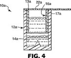
本発明の別の実施形態による容器10aが、図4に示されている。以下に述べる差異を除き、容器10aは、上述の容器10と本質的に同一である。したがって、共通の態様および特徴に関する詳細な説明を繰り返す必要はない。
A
容器10aは、その上端付近に凹部13aを有する外部筐体12aを具備している。凹部13aは、外部筐体12aの上縁部分の内周全体にわたって延在することが好ましい。
The
容器10aの内部筐体16aは上端も有し、上端は容器10aの中心長手軸に対して横方向において外側に向かって延在するフランジ17aを具備している。フランジ17aは、内部筐体16aの上縁部分の内周全体に延在し、凹部13aの中に収容される。
The
フランジ17aおよび凹部13aは、共に外部筐体12aに対する内部筐体16aの下方向の移動を阻止するための抵抗または部分ストップを提供する。外部筐体12aおよび内部筐体16aの両方の上縁へのバー22aの接合を促進するために、この抵抗は、製作中に筐体12a、16aの上端を平行な一直線に整列した関係に保持するのに役立つ。フランジ17aおよび凹部13aの形成はまた、外部筐体12aの中で大気とチャンバ14aとのシールを容易に確立することができる。
Both the
使用者が、内部筐体16aを下方向に摺動させるために、内部筐体16aに対する過度の圧力を働かせる必要がないように、フランジ17aの水平延在部の範囲はさほど大きくないことが好ましい。内部筐体16aの上縁に対して指圧を印加することによって、フランジ17aと凹部13aの下にある外部筐体12aの内面との間の締りばめ関係を容易に克服することができるように、筐体12a、16aは十分に可撓性がある。
It is preferable that the range of the horizontally extending portion of the
任意に、容器10aの製作および組立中に、半円筒のジョーを有する締付け機構が、凹部13aの付近で外部筐体12aの上部領域の外面に適用される。容器10aの組立中に、締付け機構は、筐体12a、16aが互いに対して確実に静止したままにするのに役立つ。たとえば、カバー22aを筐体12a、16aの上縁に接合している最中に、筐体12a、16aの上端を同一平面に整列した関係に保つために、締付け機構を用いることができる。
Optionally, during fabrication and assembly of the
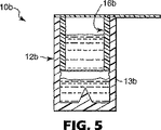
本発明の別の実施形態による容器10bが、図5に示されている。以下に述べる差異を除き、容器10bは、図4に示された容器10と本質的に同一である。
A
図5に示されているように、容器10bは、円経路に沿って延在する内部方向に指向されるフランジ13bを有する外部筐体12bを具備している。円経路は、容器10bの中心長手軸に垂直な平面に存在する。筐体12b、16bの上端が同一平面に整列した関係である間に、フランジ13bの上縁は内部筐体16bの下端に直接隣接して位置決めされる。フランジ13bおよび内部筐体16bの下端は、上述のフランジ17aおよび凹部13aの機能と類似であり、容器10bの組立中に有用であると考えられる協働して締りばめ型の抵抗を形成する。
As shown in FIG. 5, the
本発明の別の実施形態による容器10cが、図6に示されている。以下に述べる差異を除き、容器10cは、上述の容器10、10a、10bと類似である。図6において、容器10cは、水平基準面に沿って切り取った断面図で示されている(容器10cの中心長手軸が垂直方向に指向されていると仮定する)。
A
図6に示されているように、容器10cの外部筐体12cは、容器10cの中心長手軸に平行な方向に延在する1組の細長いキー溝32cを有する。さらに、容器10cの内部筐体16cは、容器10cの中心長手軸から放射方向の外側に延在する1組のキー34cを有する。キー34cが嵌合するキー溝32cに収容されるとき、外部筐体12cの底部に向かう方向に内部筐体16cを移動することができる。
As shown in FIG. 6, the
最初は、筐体12c、16cは、キー34cがキー溝32cに対して異なる回転位置にあるように指向されているため、キー溝32cに収容されていない。そのような最初の非整列配向において、キー34cは、外部筐体12cの上端部分に形成される円形水平肩(図示せず)に隣接して位置決めされる。肩は、キー34cの下方向への移動を遮断し、内部筐体16cが外部筐体12cの中で下降するのを防止する。したがって、キー34cおよび肩は、内部筐体16cの不注意による移動を防止するためのストップとして機能する。
Initially, the
しかし、一定量の組成物が必要とされるとき、使用者は、キー34cがキー溝32cと整列するまで、内部筐体16cまたは外部筐体12cを回転する。そのとき、外部筐体12cの底部に向かう下方向に内部筐体16cを移動させることができる。容器10cの残る機能および態様は、上述の容器10と類似である。
However, when a certain amount of composition is required, the user rotates the
任意に、容器10cと共に用いられるアプリケータ(図示せず)は、内部筐体16cの内部の上部凹部36cの中に適合する突出構造物を有することができる。内部筐体16cに対する静止回転位置にアプリケータを保持するために、そのような突出構造物および凹部を用いることができる。結果として、使用者は、外部筐体12cを静止状態に維持すると同時に、キー34cがキー溝32cと整列されるときまで、アプリケータをひねることによって内部筐体16cを回転することができる(またはその逆も同様)。
Optionally, the applicator (not shown) used with the
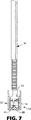
図7は、アプリケータ40を加えた上述の容器10の図である。アプリケータ40が突出する円形リブ42を具備している点を除き、アプリケータ40は、上述の「マイクロブラシ」(MICROBRUSH)というブランド名のアプリケータとある程度類似していることが好ましい。リブ42の外径は、内部筐体16の上端の外径よりわずかに小さい。結果として、使用者は、必要な場合に、カバー(すなわち、図1および図2に示されたカバー22など)を取り外して、リブ42が内部筐体16の上縁で止まるまで、アプリケータ40の先端をコンパートメントに挿入することによって、内部筐体16を下方向に移動させることができる。このとき、アプリケータ40の連続する下方向への圧力により、内部筐体16を下方向に移動させる。
FIG. 7 is a view of the
リブ42は、内部筐体16がその第2の位置に移動したときに、先端44が外部筐体12の底部または内部筐体16に接触しないように選択された距離分、先端44の外端から離隔されることが好ましい。さらに、先端44は、アプリケータ40の長手軸から横方向にずれていることが好ましい。このような構成は、特に穿刺具30が比較的鋭い場合、または使用者がアプリケータ40に過度の圧力を加える場合には、先端44が穿刺具30との接触によって変形しないようにすることを保証するのに役立つ。(図7では横方向のずれ量が異常に大きく、特に、アプリケータ40の下端部分が可撓性である場合には、示されているほど大きくずれる必要はない。)
The
任意に、リブ42の下断面は丸みを帯びている。下の丸みを帯びた断面は、アプリケータ40の中心軸を内部筐体16の中心軸と整列させるのに役立ち、内部筐体16が下方向に移動するとき、リブ42が外部筐体12に接触しないようにする。
Optionally, the lower cross section of the
図8は、容器10の内部筐体16を移動させるための装置50を示している。装置50は、内部円筒スリーブ54を加えた外部円筒スリーブ52を具備している。図8に示されているように、内部スリーブ54の半径は、内部筐体16の半径とほぼ同じである。
FIG. 8 shows an
装置50の外部スリーブ52は、外部筐体12を収容するのに十分な距離だけ内部スリーブ54から離隔される。さらに、外部スリーブ52は、内部スリーブ54より下方に延在し、丸みを帯びた内部下方周縁部を有する。このような構成は、内部スリーブ54と外部スリーブ52との間の空間に外部筐体12の上端を容易に誘導することができることを保証するのに役立つ。
The
装置50が下方向に押されるとき、内部スリーブ54は内部筐体16の上端に載り、外部スリーブ52は装置50が容器10と整列するのに役立つ。装置50が下降するとき、組成物の成分を互いに接触させることができるように、上述したように、内部筐体16が降下する。内部筐体16が下方向に移動するとき、内部筐体16の上方の空間における任意の圧力を緩和するために、内部スリーブ54は少なくとも1つのベント56を具備していることが好ましい。
When the
装置50は細長いハンドル58を具備していることが好ましい。装置50が、上述した「マイクロブラシ」(MICROBRUSH)というブランド名のアプリケータなどのアプリケータ用のハンドルの一端に取り付けられていれば、さらに好ましい。結果として、先端(アプリケータの対向する端部に位置する)を組成物の成分と接触させるために、一旦、装置50が用いられると、アプリケータを端から端まで単に回転するだけで済む。
付加的なオプションとして、装置50は、中心長手軸と整列され、アプリケータ40に着脱可能であるように連結される通路を備えていてもよい。内部筐体16を移動させるために装置50が用いられた後、装置50は所定の位置に残り、使用者が組成物を取り出すために通路を介してアプリケータの先端44を挿入する。そのような場合の装置50は、必要に応じてアプリケータ40のいずれかの端部に最初は着脱可能であるように連結されることも可能であり、あるいは、個別の要素として販売されることも可能である。
As an additional option, the
本発明の別の実施形態による容器10dが、図9に示されている。以下に述べる差異を除き、容器10dは、容器10と本質的に類似である。
A
図9に示されているように、容器10dは、内部筐体16dに加えて、外部筐体12dも具備している。内部筐体16dは、外部筐体12d内部の円筒凹部にぴったり収容される。さらに、容器10dの中心長手軸に沿った方向における内部筐体16dの全長は、外部筐体12dにおける凹部の長さと本質的に同じである。したがって、一旦、筐体12d、16dの上縁が整列される(すなわち、容器10dの中心長手軸に垂直である共通の基準面にある)と、内部筐体16dは下方向に移動することができない。
As shown in FIG. 9, the
容器10dの使用時に、カバー22dは、筐体12d、16dの上縁から剥がされる。次に、アプリケータ(「マイクロブラシ」(MICROBRUSH)というブランド名のアプリケータなど)が、内部筐体16dの脆性壁部20dに接触するまで、コンパートメント18dに挿入される。脆性壁部20dに対するアプリケータの連続圧力により、脆性壁部20dに穴が開けられ、成分26d、28dを互いに接触させることができる。
When the
混合組成物の混合および調合を促進するために、チャンバ14dの下端は半球形状であることが好ましい。オプションとして、チャンバ14dに配置されるパウチ(フォイルパウチなど)に第1の成分を収容することが可能である。付加的なオプションとして、パウチを脆性壁部20dに連結することもでき、またはパウチの上側が脆性壁部20dとして機能することも可能である。
In order to facilitate mixing and blending of the mixed composition, the lower end of the
任意に、カバー22dは壊れやすく、アプリケータによって穴を開けることができる。そのような場合には、カバー22dは筐体12d、16dから分離される必要はない。代わりに、使用者はアプリケータを用いてカバー22dおよび脆性壁部20dの両方を破り、一旦、成分が混合されると、チャンバ14dから組成物を引き出すだけで済む。そのような場合には、把持タブ(図1に示されたタブ24など)を省略することができる。
Optionally, the
上述の構成のすべてに関して、さまざまな他の変形および追加も可能である。したがって、本発明は、上記に詳細に記載された特定の現在好ましい実施形態に限定されると考えるべきではなく、むしろ、その等価物と共に以下に示す特許請求の範囲の正しい範囲によってのみ限定されると考えるべきである。 Various other variations and additions are possible for all of the above configurations. Accordingly, the invention should not be considered limited to the particular presently preferred embodiments described in detail above, but rather is limited only by the correct scope of the following claims, along with their equivalents. Should be considered.
Claims (1)
閉じた下端及び開口した上端を有する外部筐体であって、チャンバと、該下端から該チャンバ内へ上方に延びる穿刺具とを有する外部筐体と、
前記外部筐体の前記チャンバに摺動可能に収容される内部筐体であって、第1端とその反対側の第2端とを有する管状本体を備えるとともに、該第1端に接続される脆性壁部、該脆性壁部から離隔して該第2端に設けられる第1の開口部、及びコンパートメントを有する内部筐体と、
前記外部筐体の前記上端及び前記内部筐体の前記第2端に取り外し可能に設置され、前記上端の開口部及び前記第1の開口部に広がって配置されるカバーと、
前記チャンバに収容される第1成分と、
前記コンパートメントに収容される第2成分と、を具備し、
前記内部筐体は、前記脆性壁部が前記穿刺具から離隔される第1位置から、前記脆性壁部が前記穿刺具により破られて前記第1成分と前記第2成分とが互いに接触するようになる第2位置まで、前記チャンバの中で摺動可能であり、
前記第1位置から前記第2位置までの前記内部筐体の意図しない移動を阻止するためのストッパをさらに具備すること、
を特徴とする容器。In a container for a composition comprising two or more components,
An outer housing having a closed lower end and an open upper end , the outer housing having a chamber and a puncture device extending upwardly from the lower end into the chamber;
An internal housing that is slidably received in the chamber of the external housing , and includes a tubular body having a first end and a second end opposite to the first end, and is connected to the first end. an inner housing having brittle walls, a first opening portion provided in said second end spaced from該脆of walls, and the compartment ment,
A cover that is detachably installed at the upper end of the outer casing and the second end of the inner casing, and is arranged to spread over the opening of the upper end and the first opening;
A first component contained in the chamber;
A second component housed in the compartment,
The inner casing is configured so that the brittle wall portion is broken by the puncture device from the first position where the brittle wall portion is separated from the puncture device, and the first component and the second component are in contact with each other. Is slidable in the chamber to a second position,
Further comprising a stopper for preventing unintentional movement of the internal housing from the first position to the second position;
A container characterized by.
Applications Claiming Priority (2)
| Application Number | Priority Date | Filing Date | Title |
|---|---|---|---|
| US09/862,126 US6543612B2 (en) | 2001-05-21 | 2001-05-21 | Container for compositions made of two or more components |
| PCT/US2002/007016 WO2002100739A1 (en) | 2001-05-21 | 2002-03-07 | Container for compositions made of two or more components |
Publications (3)
| Publication Number | Publication Date |
|---|---|
| JP2004529044A JP2004529044A (en) | 2004-09-24 |
| JP2004529044A5 JP2004529044A5 (en) | 2005-12-22 |
| JP3971376B2 true JP3971376B2 (en) | 2007-09-05 |
Family
ID=25337732
Family Applications (1)
| Application Number | Title | Priority Date | Filing Date |
|---|---|---|---|
| JP2003503516A Expired - Fee Related JP3971376B2 (en) | 2001-05-21 | 2002-03-07 | Container for a composition comprising two or more components |
Country Status (6)
| Country | Link |
|---|---|
| US (1) | US6543612B2 (en) |
| EP (1) | EP1390275B1 (en) |
| JP (1) | JP3971376B2 (en) |
| AT (1) | ATE304495T1 (en) |
| DE (1) | DE60206159T2 (en) |
| WO (1) | WO2002100739A1 (en) |
Families Citing this family (29)
| Publication number | Priority date | Publication date | Assignee | Title |
|---|---|---|---|---|
| US7482116B2 (en) | 2002-06-07 | 2009-01-27 | Dna Genotek Inc. | Compositions and methods for obtaining nucleic acids from sputum |
| CA2424536A1 (en) * | 2003-04-10 | 2004-10-10 | Claude Juneau | Container and method for modifying the composition of a product |
| ES2377727T3 (en) * | 2003-10-16 | 2012-03-30 | Straumann Holding Ag | Package for preserving a medical device, in particular a dental implant |
| US7131784B2 (en) * | 2004-03-11 | 2006-11-07 | 3M Innovative Properties Company | Unit dose delivery system |
| US20050244216A1 (en) * | 2004-04-29 | 2005-11-03 | Michael Magraw | Coupler |
| US20060076353A1 (en) * | 2004-07-29 | 2006-04-13 | Wu Kuo C | Cap structure for a container outlet |
| US20070246381A1 (en) * | 2006-04-21 | 2007-10-25 | Pond Gary J | Telescoping ampoule device |
| WO2009114754A1 (en) * | 2008-03-14 | 2009-09-17 | Solutions Biomed, Llc | Multi-chamber container system for storing and mixing fluids |
| WO2010056871A2 (en) | 2008-11-12 | 2010-05-20 | Solutions Biomed, Llc | Two-part disinfectant system and related methods |
| JP5315074B2 (en) * | 2009-02-04 | 2013-10-16 | 株式会社大協精工 | Hygiene container |
| KR101045245B1 (en) | 2009-06-30 | 2011-06-30 | 주식회사 블리스팩 | the package with makeup goods in impregnate contents |
| FR2960131B1 (en) * | 2010-05-21 | 2012-07-27 | Claude Sebban | NEW FOOD PRODUCT |
| FR2973355B1 (en) * | 2011-03-30 | 2014-05-23 | Cadorit Ag | PACKING DEVICE SUITABLE FOR PACKING SEPARATELY A FIRST AND A SECOND FLUID |
| US9442046B2 (en) | 2011-06-19 | 2016-09-13 | Abogen, Inc. | Device for sample collection |
| CA2791626A1 (en) * | 2011-10-04 | 2013-04-04 | Biomedical Concepts Llc | Method for pre-debriding treatment of non-viable skin tissue and compositions and system therefor |
| AU2014218419B2 (en) | 2013-08-01 | 2019-05-16 | Ancestry.Com Dna, Llc | Sample collection device |
| EP3026425B1 (en) * | 2014-11-27 | 2020-05-06 | Hach Lange GmbH | Nephelometric turbidimeter vial arrangement |
| KR101717503B1 (en) * | 2015-06-30 | 2017-03-17 | 주식회사 오에이치코리아 | Apparatus for generating reactant gas in use of airborne disinfection |
| TWI589278B (en) * | 2015-11-19 | 2017-07-01 | 財團法人金屬工業研究發展中心 | Implant carrier, mixing pot, and implant carrier assembly |
| US9700397B2 (en) * | 2015-11-30 | 2017-07-11 | Metal Industries Research & Development Centre | Implant carrier, mixing pot, and implant carrier assembly |
| CN105846116A (en) * | 2016-05-19 | 2016-08-10 | 徐松炎 | Electric wire connector quick self-sealing waterproof insulating sleeve |
| EP3595536A4 (en) | 2017-03-15 | 2020-12-23 | Ancestry.com DNA, LLC | Sample collection device and method |
| US20200071054A1 (en) * | 2017-05-02 | 2020-03-05 | Csp Technologies, Inc. | Mineral entrained plastic formulations as puncturing elements |
| CA3078493A1 (en) * | 2017-10-06 | 2019-04-11 | Ancestry.Com Dna, Llc | Systems, devices, and methods for sample collection |
| JP2021504728A (en) | 2017-11-22 | 2021-02-15 | アンセストリー ドットコム ディーエヌエー リミテッド ライアビリティ カンパニー | Sampling kit with cap with selectively movable sleeve |
| US11426734B2 (en) | 2017-11-22 | 2022-08-30 | Ancestry.Com Dna, Llc | Sample collection kit including cap having selectively movable sleeve |
| US10703552B1 (en) * | 2017-12-07 | 2020-07-07 | Charlee Crocker | Drink container and concentrate |
| MX2021010260A (en) | 2019-02-27 | 2021-09-21 | Ancestry Com Dna Llc | Graphical user interface displaying relatedness based on shared dna. |
| US20230039707A1 (en) * | 2021-08-04 | 2023-02-09 | Andrew Jhonnie Spencer | Self-heating or self-cooling system and method |
Family Cites Families (40)
| Publication number | Priority date | Publication date | Assignee | Title |
|---|---|---|---|---|
| US2288895A (en) * | 1940-10-09 | 1942-07-07 | Continental Can Co | Self-heating container |
| US2612163A (en) | 1950-10-09 | 1952-09-30 | Wilson Y Norman | Container for hypodermic preparations |
| US2624011A (en) | 1951-03-27 | 1952-12-30 | Kurt G Stern | Self-developing pocket radiation dosimeter |
| US3010598A (en) * | 1953-08-12 | 1961-11-28 | Carl E Foss | Cooperating container |
| US2862616A (en) | 1958-03-17 | 1958-12-02 | Lancaster Chemical Corp | Method of packaging epoxy resins |
| US3359361A (en) | 1966-03-11 | 1967-12-19 | Hysol Corp | Insulating device for wire and cable ends |
| US3340873A (en) | 1966-05-13 | 1967-09-12 | Solowey Ida | Compartmented medical container having a rupturable diaphragm between compartments |
| DE1773584A1 (en) | 1967-06-13 | 1973-01-04 | Xerox Corp | REACTION VESSEL |
| US3750907A (en) | 1970-04-08 | 1973-08-07 | Eastman Kodak Co | Fluid containers having both relatively strong and relatively weak seals |
| ES167545Y (en) * | 1971-04-01 | 1972-02-16 | Alvarez Gil Lloret | CONTAINERS FOR COMPOSITE DRINKS. |
| DE2432290A1 (en) | 1974-07-05 | 1976-01-22 | Erich Wunsch | Plant spraying concentrate in closed capsule - is released into spraying tank from location sleeve in filler nozzle |
| US4152269A (en) | 1977-02-01 | 1979-05-01 | Warner-Lambert Company | Collection and separation device |
| ES247427Y (en) * | 1977-05-31 | 1981-06-16 | A PERFECTED CONTAINER WITH TWO COMPARTMENTS INTENDED TO CONTAIN PRODUCTS SEPARATED FROM EACH OTHER. | |
| DE3019636C2 (en) | 1979-06-08 | 1983-03-31 | Panpack AG, 9490 Vaduz | Disposable packaging for storing and dispensing small amounts of flowable materials |
| DE3303838A1 (en) | 1983-02-04 | 1984-08-09 | Mühlbauer, Ernst, Dipl.-Kaufm., 2000 Hamburg | MULTI-COMPONENT CAPSULE |
| US4538920A (en) | 1983-03-03 | 1985-09-03 | Minnesota Mining And Manufacturing Company | Static mixing device |
| US4611715A (en) | 1984-10-16 | 1986-09-16 | Sanford Redmond | Dispenser package |
| ATE55750T1 (en) * | 1986-02-03 | 1990-09-15 | Toess Steigmuehle Ag | CONTAINER ARRANGEMENT AND THEIR APPLICATION. |
| DE68903023T2 (en) * | 1988-04-18 | 1995-10-19 | Capsulit Srl | Closure for disposable bottles and the like, containing a container with a bottom that can be pierced. |
| US5163929A (en) * | 1989-03-13 | 1992-11-17 | O.P.T.I.C., Inc. | Ocular vial |
| US4952068A (en) | 1989-03-21 | 1990-08-28 | Flint Theodore R | Static mixing device and container |
| US5297698A (en) | 1991-07-25 | 1994-03-29 | Minnesota Mining And Manufacturing Company | Two-stage mixing and dispensing assembly for preparations such as dental cements |
| IL104463A0 (en) | 1992-02-03 | 1993-05-13 | Allergan Inc | Useful product delivery apparatus |
| US5395031A (en) | 1992-03-10 | 1995-03-07 | Redmond; Sanford | Stress concentrator aperture-forming means for sealed containers and packages |
| SE502003C2 (en) | 1993-11-08 | 1995-07-10 | Matts Folkoe | Salivary suction comprising a number of rigid section elements |
| US5660273A (en) | 1994-07-13 | 1997-08-26 | Centrix, Inc. | Single patient dose medicament dispenser with applicator |
| US5722829A (en) | 1995-02-27 | 1998-03-03 | Minnesota Mining & Manufacturing Co. | Cartridge dispensing system for dental material |
| FR2733398B1 (en) | 1995-04-26 | 1997-06-06 | Oreal | DEVICE FOR PACKAGING AND APPLYING MAKE-UP PRODUCTS, IN PARTICULAR MASCARA |
| AU704185B2 (en) * | 1995-07-29 | 1999-04-15 | Rocep Lusol Holdings Limited | Apparatus for mixing a fluid and a liquid |
| ES2128220B1 (en) * | 1995-12-04 | 1999-12-16 | Cusi Lab | PHARMACEUTICAL CONTAINER OF TWO SEPARATE SUBSTANCES, WITH MIXING DEVICE, DOSAGE APPLICATION AND ITS ASSEMBLY PROCESS. |
| US5735437A (en) | 1996-01-22 | 1998-04-07 | Minnesota Mining And Manufacturing | Lockable, hand-held dispenser and mixing tray for dispensing small quantities of material |
| US5780305A (en) | 1996-10-15 | 1998-07-14 | Chisum; William J. | Method for using forensic sampler |
| US5860806A (en) | 1996-11-29 | 1999-01-19 | The Kerr Corporation | Single dose dental adhesive delivery system and method and adhesive therefor |
| US5996782A (en) | 1997-04-14 | 1999-12-07 | Sealed Air Corporation | Foam in bag packaging system for manual use |
| US5989229A (en) | 1997-05-28 | 1999-11-23 | Becton, Dickinson And Company | Needle cover assembly having self-contained drug applicator |
| DE29714246U1 (en) | 1997-08-08 | 1998-12-10 | Thera Ges Fuer Patente | Device for storing and applying a flowable substance |
| US6152296A (en) * | 1998-11-06 | 2000-11-28 | Shih; Kuang-Sheng | Additive holder for a pet bottle |
| US6083002A (en) | 1999-02-04 | 2000-07-04 | 3M Innovative Properties Co. | Cartridge for dispensing liquid compositions |
| US6095813A (en) | 1999-06-14 | 2000-08-01 | 3M Innovative Properties Company | Method for applying a dental composition to tooth structure |
| DE10029830B4 (en) | 2000-06-16 | 2008-04-10 | Voco Gmbh | Device for storing and applying a one- or multi-component flowable substance |
-
2001
- 2001-05-21 US US09/862,126 patent/US6543612B2/en not_active Expired - Fee Related
-
2002
- 2002-03-07 WO PCT/US2002/007016 patent/WO2002100739A1/en active IP Right Grant
- 2002-03-07 AT AT02709803T patent/ATE304495T1/en not_active IP Right Cessation
- 2002-03-07 JP JP2003503516A patent/JP3971376B2/en not_active Expired - Fee Related
- 2002-03-07 EP EP02709803A patent/EP1390275B1/en not_active Expired - Lifetime
- 2002-03-07 DE DE60206159T patent/DE60206159T2/en not_active Expired - Lifetime
Also Published As
| Publication number | Publication date |
|---|---|
| US20020170834A1 (en) | 2002-11-21 |
| DE60206159T2 (en) | 2006-07-06 |
| DE60206159D1 (en) | 2005-10-20 |
| JP2004529044A (en) | 2004-09-24 |
| EP1390275B1 (en) | 2005-09-14 |
| US6543612B2 (en) | 2003-04-08 |
| EP1390275A1 (en) | 2004-02-25 |
| ATE304495T1 (en) | 2005-09-15 |
| WO2002100739A1 (en) | 2002-12-19 |
Similar Documents
| Publication | Publication Date | Title |
|---|---|---|
| JP3971376B2 (en) | Container for a composition comprising two or more components | |
| US8016161B2 (en) | Package and dispensing system | |
| AU2005222573B2 (en) | Unit dose delivery system for two-component composition | |
| US7374040B2 (en) | Devices for storing and dispensing compositions | |
| EP2233105A1 (en) | Delivery system for dental materials | |
| JP2004515424A (en) | Package and dispense actuator for multi-component compositions | |
| JP2003175077A (en) | Single patient dose medicament dispenser with applicator | |
| JP4271945B2 (en) | Container for multi-component composition | |
| JP2017214122A (en) | Additive addition structure and mixture container set | |
| US20120017412A1 (en) | Package and dispensing system | |
| EP2662050A2 (en) | Device for providing a dental material and method of its manufacture | |
| WO2009058343A1 (en) | Package and dispensing system | |
| JP2004283827A (en) | Application apparatus | |
| US20240058097A1 (en) | A dispensing gun for delivering a material from a cartridge | |
| WO2002094683A1 (en) | A package for a dental material | |
| US20030047466A1 (en) | Unit-dose packaging system | |
| US20020175185A1 (en) | Package for a dental material | |
| AU2001264758A1 (en) | A package for a dental material |
Legal Events
| Date | Code | Title | Description |
|---|---|---|---|
| A521 | Request for written amendment filed |
Free format text: JAPANESE INTERMEDIATE CODE: A523 Effective date: 20050307 |
|
| A621 | Written request for application examination |
Free format text: JAPANESE INTERMEDIATE CODE: A621 Effective date: 20050307 |
|
| A977 | Report on retrieval |
Free format text: JAPANESE INTERMEDIATE CODE: A971007 Effective date: 20060928 |
|
| A131 | Notification of reasons for refusal |
Free format text: JAPANESE INTERMEDIATE CODE: A131 Effective date: 20061003 |
|
| A601 | Written request for extension of time |
Free format text: JAPANESE INTERMEDIATE CODE: A601 Effective date: 20061228 |
|
| A602 | Written permission of extension of time |
Free format text: JAPANESE INTERMEDIATE CODE: A602 Effective date: 20070111 |
|
| A521 | Request for written amendment filed |
Free format text: JAPANESE INTERMEDIATE CODE: A523 Effective date: 20070403 |
|
| TRDD | Decision of grant or rejection written | ||
| A01 | Written decision to grant a patent or to grant a registration (utility model) |
Free format text: JAPANESE INTERMEDIATE CODE: A01 Effective date: 20070508 |
|
| A61 | First payment of annual fees (during grant procedure) |
Free format text: JAPANESE INTERMEDIATE CODE: A61 Effective date: 20070607 |
|
| R150 | Certificate of patent or registration of utility model |
Free format text: JAPANESE INTERMEDIATE CODE: R150 |
|
| FPAY | Renewal fee payment (event date is renewal date of database) |
Free format text: PAYMENT UNTIL: 20110615 Year of fee payment: 4 |
|
| FPAY | Renewal fee payment (event date is renewal date of database) |
Free format text: PAYMENT UNTIL: 20110615 Year of fee payment: 4 |
|
| FPAY | Renewal fee payment (event date is renewal date of database) |
Free format text: PAYMENT UNTIL: 20120615 Year of fee payment: 5 |
|
| LAPS | Cancellation because of no payment of annual fees |