JP3970574B2 - Sealing device - Google Patents
Sealing device Download PDFInfo
- Publication number
- JP3970574B2 JP3970574B2 JP2001321744A JP2001321744A JP3970574B2 JP 3970574 B2 JP3970574 B2 JP 3970574B2 JP 2001321744 A JP2001321744 A JP 2001321744A JP 2001321744 A JP2001321744 A JP 2001321744A JP 3970574 B2 JP3970574 B2 JP 3970574B2
- Authority
- JP
- Japan
- Prior art keywords
- seal
- shaft
- sealing
- lip
- ring
- Prior art date
- Legal status (The legal status is an assumption and is not a legal conclusion. Google has not performed a legal analysis and makes no representation as to the accuracy of the status listed.)
- Expired - Lifetime
Links
Images


Description
【0001】
【発明の属する技術分野】
本発明は、シールリップを有して軸をシールするシール装置に関する。更に詳しくは、高圧な冷媒等の被密封流体を耐圧性を有してシールリップによりシールできるようにすると共に、シール部面の密封に優れた面圧を容易に設計可能にしたシール装置に関する。
【0002】
【従来の技術】
本発明のシール装置に係わる従来技術1として、実開平3−41264号公報に示すリップ型シールが存在する。
図6は、この公報に開示されたリップ型シール100の半断面図である。 このシール型リップ100は、カークーラーのコンプレッサ用のリップ型シールである。このため、環境への影響を配慮してフロンガスから二酸化炭素ガスに変更された被密封流体をシールするように考慮されている。
このために、リップ型シール100は、図6に示すように構成されている。
この図6において、補強環103を埋設した基部102からシールリップ101が被密封流体側に傾斜して延びた端部104に回転軸113の外周面と密接するシール面104aを設けている。このシール面104aを緊迫するガータスプリング105が端部104の外周面に設けられた環状溝の中心線Pに装着されている。このガータスプリング105を装着する環状溝に対してシール面104aの軸方向の位置寸法を正確に設定しなければならない。
【0003】
又、シールリップ101の大気側である内周面と回転軸113との間には、環状を成す金属材製のバックアッププレート(バックアップリング)106がシールリップ101の内周面に軽く接触嵌合する状態で配置されている。更に、バックアッププレート106の大気側には、回転軸113と嵌合する密接部108を設けた樹脂材製の環状リップ部107がバックアッププレート106と同形状に配置されている。又、リップ部107の大気側にはリング状のサポートプレート109がが配置されている。そして、バックアッププレート106と、環状リップ部107と、サポートプレート109とは外周部が断面コの字形の保持リング110により挟持されている。この挟持された三部品全体がシール部で、並列されたシールリップ101を補助している。
【0004】
このシール部は、シールリップ101と並列に配列されて被密封流体の圧力に対してシールリップ101を二重にシールする形に支持している。
このために、シール部はシールリップ101と分離されて並列に配置され、バックアッププレート106によりシールリップ101を支持しているので、この両者の組み合わせが正確でないと、シール面104aの面圧を軸に対してシール能力が発揮できるように接合させることが困難になる。又、このシールリップ101とシール部とが分離されており、各々を製作するためにコスト高になっている。又、この両者の組み付けも、精度を必要とするから、コスト高になる。
【0005】
又、シールリップ101の先端部のシール面104aと環状溝との距離も正確に製作しなければならないが、シールリップ101がゴム材製であるから変形しやすく、ゴム成形上、この距離寸法を確保することが困難になっている。更に、バックアップリング106とシールリップ101との接合も正確に接合させなければならず、シールリップ101に対してバックアップリング106を圧接するとシールリップ101が回転軸外周面から浮き上がるのでシール能力を悪化させることになる。
【0006】
更に他の従来技術2として、特開2000−179702号公報が存在する。この公報に記載の軸封装置200は、図7に示すように構成されている。図7はこの軸封装置200の半断面図である。軸封装置200は、自動車の圧縮機に用いられるものであって、その圧縮機の被密封流体が二酸化炭素ガスである。そして、全体構成は従来技術1とほぼ同様に形成されているが、バックアップリングに相当する金属薄板(バックアップリング)206は両者の目的が異なり、従来技術2は被密封流体の透過を防止する目的にあわせてシールリップ201とシール部208とを一体化したものが開示されている。
この軸封装置200は、外周に波状のシール部207を設けた嵌着部202から筒状のシールリップ201が形成されている。又、シールリップ201の大気側に樹脂材製のシール部208が設けられている。
このゴム材製のシールリップ201と樹脂材製のシール部208との間には、金属薄板206が配置されている。そして、ゴム材製のシールリップ201では、二酸化炭素ガスが透過しやすいので、この金属薄板206により二酸化炭素の透過を防止しようとするものである。このために金属薄板206は、シールリップ201とシール部208との間で、シールリップの大気側の全面に貼り付けるような形で介在されている。
【0007】
しかし、この薄板金属のバックアップリング206では、シールリップ201が回転軸213に対して常に密接するように支持することは、構成的にも強度的にも困難である。つまり、シールリップ201のシール部204aが弾性力で回転軸213に対して強く圧接するのをバックアップリング206により拡張することは透過を目的にする構成では困難である。それは、シールリップを引き伸ばして拡張するとガスが急速に透過しやすくなるからである。
更に、被密封流体の圧力によりシール部204aが押圧されて回転軸213にべた当たりに圧接するのを、このバックアップリング206により防止することは困難である。
更には、バックアップリング206は、薄肉金属であるために、シールリップ206のシール部204aを回転軸213に最適に圧接するように緊迫に拡張して保持することも困難である。
【0008】
【発明が解決しようとする課題】
上述のような従来技術では、シール装置を軸に嵌挿するとき、シールリップのシール部の内径が軸の外径と密接させている。この密接が強すぎても、反対に弱すぎてもシャープな面圧が形成できないから、被密封流体が漏洩することになる。このためにシール部の内径を軸に対して最適な内径になるように挿入接合させようとしている。しかし、ゴム材製のシールリップのシール部を拡張して軸を圧入することは、ゴムの摩擦抵抗が大きいことから困難である。このために、摩擦抵抗によりシール部は軸の挿入方向に伸ばされてシール面が軸に不正常に嵌合する。そして、シール部の軸周面との対向角度が小さく変形された嵌合状態で軸と広く接面した状態でシールすることになる。この嵌合状態は、軸周面との接触面積が大きくなるので、シャープな面圧が形成されずにシール能力を悪化させる。その結果、被密封流体を漏洩させることになる。
【0009】
又、シール部が軸に強く圧接すると、接触面積が増加するから、面圧がなだらかになりシール能力が悪化すると共に、シール面の摩擦により、シール面にスラッジが生成して摩耗を促進させることになる。そして、シール能力を低下させる結果となる。
更に、上述の状態で被密封流体の圧力が高圧になると、シール部の軸周面との摩擦が大きくなり、シール面の摩耗を促進することになる。
【0010】
本発明は上述のような問題点に鑑み成されたものであって、その発明が解決しようとする技術的課題は、シール装置のシール部に軸を挿入してもシール部が軸とシャープな面圧状態で密接させることにある。
又、シール部が軸に対してシャープな面圧状態で密接させて、シール能力を向上させることにある。同時に、シール部が被密封流体からの圧力を受けても軸周面に対して接触面積を大きくならないように保持し、シール部の摩耗を防止することにある。更に、これらのシール部面の設計を構造簡単な組み合わせにより容易にできるようにすることにある。
【0011】
【課題を解決するための手段】
本発明は、上述のような技術的課題を解決するために成されたものであって、その技術的解決手段は以下のように構成されている。
【0012】
請求項1に係わる本発明のシール装置は、嵌合孔を有するハウジングと前記ハウジングの嵌合孔に嵌装する軸との間を密封するシール装置であって、
前記ハウジングの嵌合孔に密封嵌着する嵌着部から筒状に被密封流体側へ延びた先端のシール部の内周面に傾斜した大気側シール部面を有すると共に前記大気側シール部面の先端に前記軸周面と密封接触するシール角部を有するゴム状弾性材製のシールリップと、
前記大気側シール部面に設けた軸芯に対して傾斜角度で傾斜した拡張テーパ面と、
前記嵌着部に一端部が保持されて前記シールリップの内周に対向する筒状に形成されて先端に前記拡張テーパ面と嵌合する軸芯に対して傾斜角度で傾斜した傾斜支持部を有する前記ゴム状弾性材より硬質材の樹脂又はアルミニウム材製の支持環と、
前記支持環の傾斜支持部の端部に前記軸と近接又は摺動嵌合する内端面を設けたリング部分とを有し、
前記拡張テーパ面の軸周面に対する傾斜角度が前記傾斜支持部の軸周面に対する傾斜角度より大きい角度に形成されていると共に前記拡張テーパ面に前記傾斜支持部が嵌合されて前記拡張テーパ面の傾斜角度が前記傾斜支持部の傾斜角度にほぼ等しい角度に弾性変形され且つ被密封流体の圧力の増大に応じて前記リング部分が前記軸に支持されるとともに前記シール部を支持する構成にされているものである。
【0013】
この請求項1に係わる本発明のシール装置では、シールリップに於ける拡張テーパ面に支持環の傾斜支持部を圧入嵌合してシール角部の径を拡張し、しかも、傾斜支持部で傾斜した拡張テーパ面を圧接保持しているので、大気側シール部面を一定の角度に保持することができるとともに、傾斜支持部の傾斜した広い面のテーパ面によりシール部が受ける被密封流体の圧力に対して耐圧能力を発揮することができる。そして、この保持された緊迫状態のシール角部が軸の外周面と図5および図6に示すような面圧分布Pのシャープな面圧で密接でき、シール角部のシールが確実に発揮される。
同時に、大気側シール部面が軸と小さな接触面積で接触するように構成されているので、シール装置を軸に挿入してもシール部面が軸により軸の挿入方向へ伸ばさせることもなく、シール部面が押し込まれた異常な変形によりシール能力が低下するのを効果的に防止する。その結果、シール角部がシャープな面圧で接触する状態を保持し、被密封流体に対して優れたシール能力を発揮する。
更に、高圧又は変動圧の被密封流体がシール部に作用すると、軸と接触する構成のリング部分によりシール部はさらに支持される構成であるから、大気側シール部面を一定の角度に保持することができる。このため、この大気側シール部面が支持環の傾斜支持部により拡張された最適な締め代状態によるシャープな面圧で接触できるので、高圧の被密封流体がシールリップに作用しても、シール角部が軸周面に対して面積を大きくするような接触状態になるのが防止されてシール角部のシール効果を発揮する。同時に、シール角部の軸に対する摩擦抵抗は小さくなり、その摩擦による摩耗を防止することができる。
【0014】
請求項2に係わる本発明のシール装置は、前記支持環の傾斜支持部の傾斜角度が前記シールリップの原形の前記拡張テーパ面の傾斜角度より4°から8°の範囲で小さく形成されているものである。
【0015】
この請求項2に係わる本発明のシール装置では、支持環の傾斜支持部によりシールリングの大気側シール部面を4°から8°の同角度だけ小さく形成された状態では、シール部面が最もシャープな面圧になるような緊迫力に保持されるから、最適な密接状態でシール能力が発揮される。
又、大気側シール部面は角度が4°から8°の範囲に鋭角になるから軸の挿入が容易になり、軸の挿入によりシール角部が変形状態で密接することもなく、密封能力が発揮される。
更に、大気側シール部面は拡張テーパ面を介して傾斜支持部により拡径された状態でシール角部が軸外周面と締め代を有して密接してシール効果を発揮すると共に、シール部が被密封流体の圧力を受けても、シール部面は緊迫状態にあるので、軸外周面と大きな面積で接面するのが防止される。このためにシール部面は、摩擦抵抗が小さく、長期にわたり摩耗が防止される。
【0016】
請求項3に係わる本発明のシール装置は、前記シールリップの前記拡張テーパ面は前記傾斜支持部により拡径された状態で前記シール角部が前記軸の外径より0.8mmから2.0mmの小径寸法に形成された締め代で嵌合しているものである。
【0017】
この請求項3の本発明のシール装置では、シールリップの拡張テーパ面が傾斜支持部により拡張された状態で、シール部面が軸に0.8mmから2.0mmの締め代で嵌合するように構成されているから、シール部面のシール角部が軸周面とシャープな面圧で密封接触してシール能力が向上する。
更に、このシール角部の締め代の範囲ではシール面の摺動抵抗が小さく、そのシール部面の摩耗が長期にわたり防止できる。
【0022】
【発明の実施の形態】
以下、本発明に係わる好ましい実施の形態のシール装置を、その図面に基づいて詳述する。尚、以下に説明する各図面は、所謂、特許用の概念図ではなく、寸法関係が正確な設計図である。
【0023】
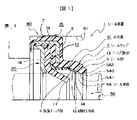
図1は、本発明に係わる第1実施の形態のシール装置を示すものであって、軸に装着されない状態の半断面図である。又、図2は図1に於けるシール装置1に軸が装着された状態のシール部である要部を示す断面図である。
この図1において、1は、シール装置である。シール装置1には、ハウジング60の嵌合孔61に嵌着するゴム材製の嵌着部7が設けられている。この嵌着部7の外周面には、凸部状のシール部分7Aが形成されている。又、嵌着部7には、補強環8が埋設されており、この補強環8によりハウジング60との嵌着を強固にすると共に、嵌着部7に第2シールリップ15、背板リング20等の接合部品を保持するものである。
【0024】
又、この補強環8を介してゴム材製のシールリップ3が嵌着部7から回転軸50に向かって傾斜した筒状に形成されている。このシールリップ3の内端には、シール部5が形成されており、このシール部5の内面はシール部面5Aに形成されている。このシール部面5Aの断面が3角状のシール角部5A3をなし、そのシール角部5A3の両面が大気側シール部面5A1と被密封流体側シール部面5A2とに形成されている。このシール角部5A3によりシール機能面を成し、このシール角部5A3が回転軸50に最適に密接すると面圧を高めてシール能力を発揮する。
更に、シールリップ3のシール部5の付け根には、円筒内面から断面なめらかなに折り曲げられて傾斜した大気側シール部面5A1に連面する拡張テーパ面4が形成されている。
【0025】
シールリップ3の嵌着部7から拡張テーパ面4側には、シールリップ3の面に沿ってほぼシールリップ3と同様な形状の樹脂材製の支持環10が設けられている。この支持環10の外周保持部11は嵌着部7に挟持されている。
更に、支持環10の内周端は傾斜支持部12に形成されている、この傾斜支持部12はテーパ面に形成されてシールリップ3の拡張テーパ面4と圧入嵌合するように構成されている。この傾斜支持部12が拡張テーパ面4に圧入されることによりシール部面5Aが所定の寸法だけ拡径されるように成されている。
又、この支持環10の内端がリング部分13に形成されている。このリング部分13の内端面14には、回転軸50に接触しない範囲の内径に形成されている。この支持環10は、樹脂成形により、一端がフランジ状で中間が円筒状に形成されている。そして、支持環10は、シールリップ3に被密封流体の圧力を受けても変形しない耐圧性を有する厚さに形成されている。
【0026】
更に、支持環10の大気側内周面には、樹脂材製の第2リップシール15が設けられている。この第2シールリップ15は、外周が径方向を成すリング状の挟持部16に形成されており、内周が挟持部16から傾斜したリップ部17に形成されている。そして、リップ部17の内端側が回転軸50に圧入嵌合して筒状を成し、回転軸50をシールする。
【0027】
更に又、支持環10の外周支持部11と、第2シールリップ15の挟持部16とを大気側から支持する背板リング20が設けられている。この背板リング20は金属製で内端が第2シールリップ15の折曲部を支持しするように曲部に形成されている。
【0028】
この支持環10の外周支持部11と、第2シールリップ15の挟持部16と、背板リング20とは、補強環8により圧着されるようにして嵌着部7に挟持されている。そして、補強環8は嵌着部7のゴムにより覆われている。
【0029】
図2は、図1のシール装置1に回転軸50を装着した状態の要部の断面図である。この図2に示す仮想線のシールリップ3Aは原形図であり、シールリップ3の拡張テーパ面4及びシール部面5Aが回転軸50の寸法に対して拡張できるように原形では小径に形成されている。そして、支持環10の傾斜支持部12をシールリップ3の拡張テーパ面4に圧入してシール部5を拡張すると図2に示す実線のシールリップ3ように弾性変形する。この拡張テーパ面4が傾斜支持部12の圧入拡張によりシール部面5Aの内径寸法は、0.1mmから3,2mmまでの範囲で原形より拡径される。このシール部面5Aの拡径は回転軸50の径の大きさに対応して決められる。更に好ましくは、シール部面5Aの内径は1mmから2.2mmまでの範囲で拡張すると良い。更に、シール部面5Aの内径は、回転軸50の直径に対して0.6mmから2.2mmの範囲で小径に形成すると良い。更に好ましくは、シール部面5Aの内径は0.8mmから1.6mmの範囲で小径にすると良い。
【0030】
又、拡張テーパ面4に傾斜支持部12を圧入すると大気側シール部面5A1の回転軸50の周面に対する軸方向角度は、原形である仮想線のそれより小さくなる。このために回転軸50のシール部面5Aへの挿入は容易になる。その結果、シール部面5Aへの回転軸50の挿入によりシール部5は回転軸50挿入方向へ伸ばされることもなく、シール角部5A3の回転軸50への密接はシャープな面圧となり、シール効果を発揮する。
更に、拡張テーパ面4に傾斜支持部12を圧入すると、シール部面5Aのシール角部5A3は、回転軸50に対して締め代を設けた寸法内で拡径されるので、シール角部5A3の面圧がシャープな圧力分布Pを形成してシール能力を発揮する。
【0031】
又、支持環10を樹脂材製にすると、金属材製に対してよりも弾力性があり、ゴム材製のシールリップ3に対して複合的な弾力性を付与するので、シール能力が発揮される。更に、支持環10が樹脂材製であると回転軸50と接触又は摺動するようなことが生じても、摺動抵抗が小さいので接触面に対して摩耗の惹起を防止する。
又、支持環10の内端面14を回転軸50に対して近接又は摺動接触させることが可能になる。その結果、支持環10のリング部分13によりシール部5を効果的に支持して、被密封流体の高圧力に対してシール部5の耐圧性を発揮することができる。
【0032】
更に又、シール部5は拡張された分だけ緊迫されている上に、傾斜支持部12により拡張テーパ面4に連面する大気側シール部面5A1の近傍が支持されているから、被密封流体の圧力がシール部5の外周面に対して強く作用しても耐圧性を発揮することができる。更に、例え、第2シールリップ15によりシールリップ3から漏洩した被密封流体はシールされるから、シール部面5Aの大気側は圧力が上がるので、シール部5は被密封流体からの圧力に対して耐圧性を発揮する。
【0034】
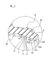
図3は、本発明の第2実施の形態を示すシール装置1の要部を示す半断面図である。
図3に於いて、図2のシール装置1と相違する点は支持環10の傾斜支持部12の内端に設けたリング部分13の内端面14の直径をさらに小径にした点である。そして、シールリップ3についてはほぼ他の実施例と類似する。
図3の仮想線はシールリップ3Aの原形を示すものである。又、実線は、シールリップ3の拡張テーパ面4が傾斜支持部12により拡張された状態図である。
この図3において、大気側シール部面5A1のテーパ角度θ1と傾斜支持部4のテーパ角度θ2はほぼ同一角度であり、仮想線のシールリップ3Aの大気側シール部面5A1のテーパ角度θ0はθ1及びθ2よりも3°から10°大きな角で形成されている。この3°から10°は拡張される角度である。
【0035】
図4は第3実施の形態に係わるシール装置1のシールリップを示す要部断面図である。
支持環10の傾斜支持部12を図4に示す仮想線のシールリップ3Aの拡張テーパ面4に圧入すると、図3または図4に実線で示すようなシールリップ3の形状に弾性変形する。そして、支持環10の傾斜支持部12を拡張テーパ面4に圧入することによりシール部面5Aのシール角部5A3も図3に示すように拡張されるから、シール角部5A3の回転軸50に対する接触面は、図4のPmaxのような面圧分布Pがシャープな形に形成される。
このためにシール能力が向上する。特に、面圧分布Pに於いて被密封流体側がシャープな形になることは、被密封流体をシールする能力に優れていることを示すものである。
又、シール部面5Aの大気側シール部面5A1は、図3における仮想線に比べて回転軸50に対する傾斜角度θ1が小さくなるので、回転軸50の挿入により回転軸50の挿入方向に伸ばされて異常変形するのが防止される。このためにシール能力が向上する。
【0036】
次に、支持環10を樹脂材製にすると、リング部分13の内端面14を回転軸50に近接又は摺動嵌合することができる。更に、回転軸50の挿入をしやすくするために、更には、接触面積を少なくするために、内端面14を挿入方向に収斂するテーパ面に形成することもできる。そして、被密封流体の圧力が高圧になっても、リング部分13によりシール部5を効果的に支持することが可能になる。例え、被密封流体の圧力により内端面14が回転軸50に接触しても、樹脂材製の内端面14は摺動抵抗を小さく、しかも接触面積を小さく保持することが可能になる。その結果、シール部面5Aの被密封流体の圧力に対する耐圧性が向上する。
【0037】
図5は、本発明の第4実施の形態を示すシール装置の要部を示す半断面図である。図5は、回転軸50に装着したシールリップ3の装着状態図である。そして、図5に示すシールリップ3は拡張テーパ面4が大気側シール面部5A1に同一角度で連続面に形成されている。又、支持環10の傾斜支持部12はテーパ面状に形成されており、傾斜支持部10を拡張テーパ面4に圧入することにより、シール部面5Aを回転軸50に対して拡径することができる。この支持環10は、金属材でも、例えば、アルミニウムなどの軟材で製作される。
この拡張テーパ面4を全面がテーパを成すように傾斜させた傾斜面状に形成するとシール角部5A3の接触面積を任意に設定する設計が容易になる。このシール角部5A3の接触面積の設定により、シール角部5A3の面圧分布PをPmaxのようにシャープに形成することが可能になる。
又、大気側シール部面5A1の角度を小さな角度に弾性変形させることにより、回転軸50の挿入による異常変形を防止することが可能になる。このために、シール部面5Aのシール能力が向上する。
【0038】
【発明の効果】
本発明に係わるシール装置によれば、以下に記載するような優れた効果を奏する。
【0039】
請求項1に係わる本発明のシール装置によれば、シールリップに於ける拡張テーパ面に支持環の傾斜支持部を圧入してシール部面を拡張し、しかも、傾斜支持部により拡張テーパ面に接面する大気側シール部面を一定の角度に保持することができる。このためにシール効果を発揮させるための設計が容易になる。さらに、この保持された緊迫状態のシール部面が軸の外周面とシャープな面圧で密接できる。このためにシール部面が優れた効果を奏する。
同時に、シール部面が軸と小さな接触面積で接触できるので、シール装置を軸に挿入してもシール部が軸により軸の挿入方向へ伸ばさせることもなく、シール部面が異常な変形によりシール能力が低下するのを効果的に防止すると共に、シール角部がシャープな面圧で接触する状態を保持し、優れたシール効果を奏する。
更に、このシール部面が支持環の傾斜支持部により拡径されてシャープな面圧で接触する状態に保持させているので、高圧の被密封流体がシールリップに作用しても、シール部面が軸周面に対して面積を大きくするような接触状態にはならないから、シール部面の摩擦抵抗は小さく、その摩擦による摩耗を防止する効果を奏する。
【0040】
請求項2に係わる本発明のシール装置によれば、支持環の傾斜支持部によりシールリングの大気側シール部面を4°から8°の角度に形成された状態では、シール部面が最もシャープな面圧になるような緊迫力に保持されるから、最適な密接状態でシール効果が発揮される。
又、拡張テーパ面に傾斜支持部を圧入することにより、大気側シール部面は角度が鋭角になるから軸の挿入を容易し、軸の挿入によりシール角部が変形状態で密接することもなく、密封能力が向上する効果を奏する。
更に、大気側シール部面は拡張テーパ面を介して傾斜支持部により拡径された状態でシール角部が軸外周面と締め代を有して密接するから、シール効果を発揮すると共に、シール部が被密封流体の高い圧力を受けても、シール部面は緊迫状態にあるので、軸外周面と大きな面積で接面するのが防止される。このためにシール部面は、摩擦抵抗が小さく、長期にわたり摩耗が防止される効果を奏する。
【0041】
請求項3に係わる本発明のシール装置によれば、シールリップの拡張テーパ面が傾斜支持部により拡張された状態で、シール部面が軸に0.8mmから2.0mmの締め代で嵌合するように構成されているから、シール部面のシール角部が軸周面とシャープな面圧で密封接触してシール能力が向上する効果を奏する。
更に、このシール角部の締め代の範囲ではシール面の摺動抵抗は小さく、そのシール部面の摩耗が防止できる効果を奏する。
【図面の簡単な説明】
【図1】本発明の第1実施の形態に係わるシール装置に回転軸が装着されない前の半断面図である。
【図2】図1に示すシール装置に回転軸を装着した状態の回転軸側要部の半断面図である。
【図3】本発明の第2実施の形態に係わるシール装置に回転軸が装着された状態の回転軸側要部の半断面図である。
【図4】本発明の第3実施の形態に係わるシール装置に回転軸が装着された状態の回転軸側要部の半断面図である。
【図5】本発明の第4実施の形態に係わるシール装置に回転軸が装着された状態の回転軸側要部の半断面図である。
【図6】従来技術1のシール装置の半断面図である。
【図7】従来技術2のシール装置の半断面図である。
【符号の説明】
1 シール装置
3 シールリップ
3A 原形シールリップ
4 拡張テーパ面
5 シール部
5A シール部面
5A1 大気側シール部面
5A2 被密封流体側シール部面
5A3 シール角部
7 嵌着部
7A シール部分
8 補強環
10 支持環
11 外周保持部
12 傾斜支持部
13 リング部分
14 内端面
15 第2シールリップ
16 挟持部
17 リップ部
20 背板リング
25 Oリング
50 回転軸
60 ハウジング
61 環着孔[0001]
BACKGROUND OF THE INVENTION
The present invention relates to a sealing device having a seal lip to seal a shaft. More particularly, the present invention relates to a sealing device that enables a sealed fluid such as a high-pressure refrigerant to be sealed with a sealing lip while having a pressure resistance, and that can easily design a surface pressure excellent in sealing a seal portion surface.
[0002]
[Prior art]
As
Figure6These are the half sectional views of the
For this purpose, the
This
[0003]
Also, an annular metal backup plate is formed between the inner peripheral surface on the atmosphere side of the
[0004]
This seal portion is arranged in parallel with the
For this reason, the seal portion is separated from the
[0005]
Also, the distance between the seal surface 104a at the tip of the
[0006]
Still another
In this
A
[0007]
However, in this thin
Further, it is difficult to prevent the seal portion 204a from being pressed by the pressure of the sealed fluid and coming into pressure contact with the rotating
Furthermore, since the
[0008]
[Problems to be solved by the invention]
In the prior art as described above, when the sealing device is fitted on the shaft, the inner diameter of the seal portion of the seal lip is in close contact with the outer diameter of the shaft. If this closeness is too strong or too weak, a sharp surface pressure cannot be formed, and the sealed fluid will leak. Therefore, try to insert and join so that the inner diameter of the seal part is the optimal inner diameter with respect to the shaft.Shiing. However, it is difficult to press-fit the shaft by expanding the seal portion of the rubber seal lip because the frictional resistance of rubber is large. For this reason, the seal portion is extended in the insertion direction of the shaft by the frictional resistance, and the seal surface is improperly fitted to the shaft. And it seals in the state which contact | connected the shaft widely in the fitting state by which the opposing angle with the axial peripheral surface of a seal | sticker part was deform | transformed small. In this fitted state, since the contact area with the shaft peripheral surface is increased, the sealing ability is deteriorated without forming a sharp surface pressure. As a result, the sealed fluid is leaked.
[0009]
In addition, if the seal part is pressed strongly against the shaft, the contact area increases, so that the surface pressure becomes gentle and the sealing ability deteriorates, and the friction of the seal surface generates sludge on the seal surface to promote wear. become. As a result, the sealing ability is reduced.
Furthermore, when the pressure of the sealed fluid becomes high in the above-described state, friction with the shaft peripheral surface of the seal portion increases, and wear of the seal surface is promoted.
[0010]
The present invention has been made in view of the above problems, and the technical problem to be solved by the present invention is that the seal portion is sharp with the shaft even if the shaft is inserted into the seal portion of the seal device. It is in close contact with the surface pressure.
Another object is to improve the sealing performance by bringing the seal portion into close contact with the shaft in a sharp surface pressure state. At the same time, even if the seal part receives pressure from the fluid to be sealed, the seal area is held so that the contact area does not increase with respect to the shaft peripheral surface, and wear of the seal part is prevented. Further, another object of the present invention is to make it easy to design the seal portion surfaces by a simple structure combination.
[0011]
[Means for Solving the Problems]
The present invention has been made to solve the technical problems as described above, and the technical solution means is configured as follows.
[0012]
The sealing device of the present invention according to
The atmosphere-side seal part surface has an inclined atmosphere-side seal part surface on the inner peripheral surface of the seal part at the tip extending in a cylindrical shape from the fitting part sealingly fitted in the fitting hole of the housing to the sealed fluid side A sealing lip made of a rubber-like elastic material having a sealing corner portion in sealing contact with the peripheral surface of the shaft at the tip thereof,
Provided on the atmosphere side seal part surfaceInclined at an inclination angle with respect to the axisAn extended tapered surface;
One end portion is held by the fitting portion, and the inner periphery of the seal lipOppositeIt is formed in a cylindrical shape and fits with the extended tapered surface at the tipInclined at an inclination angle with respect to the axisIt is harder than the rubber-like elastic material having an inclined support part.Made of resin or aluminumWith support ring,
A ring portion provided with an inner end face close to or slidably fitted to the shaft at the end of the inclined support portion of the support ringAnd
The expansion taper surface is formed such that an inclination angle of the expansion taper surface with respect to the axial peripheral surface is larger than an inclination angle with respect to the axial peripheral surface of the inclination support portion, and the expansion support surface is fitted to the inclination taper surface. Is inclined to an angle substantially equal to the inclination angle of the inclined support portion.In addition, the ring portion is supported by the shaft and supports the seal portion in response to an increase in the pressure of the sealed fluid.Is.
[0013]
In the sealing device of the present invention according to
At the same time, since the atmosphere side seal part surface is configured to contact the shaft with a small contact area, even if the seal device is inserted into the shaft, the seal part surface does not extend in the shaft insertion direction by the shaft, Effectively prevents the sealing ability from being reduced due to abnormal deformation of the seal surface being pushed in.. as a result,Keeping the seal corners in contact with sharp surface pressure,For sealed fluidExhibits excellent sealing ability.
Furthermore,When the sealed fluid of high pressure or fluctuating pressure acts on the seal part, the seal part is further supported by the ring part configured to come into contact with the shaft, so that the atmosphere side seal part surface can be held at a certain angle. it can. For this reason,This atmosphere side seal part surface is expanded by the inclined support part of the support ring.TheContact with sharp surface pressure due to optimal tightening allowanceCanTherefore, even when a high-pressure sealed fluid acts on the seal lip, it is possible to prevent the seal corner from coming into contact with the shaft circumferential surface to increase the area.Show the sealing effect at the corner of the sealTheat the same time,Seal cornerAgainst the axisFriction resistance is smallBecomeTherefore, wear due to the friction can be prevented.
[0014]
In the sealing device of the present invention according to
[0015]
In the sealing device according to the second aspect of the present invention, in the state where the atmosphere side seal portion surface of the seal ring is formed by the same angle of 4 ° to 8 ° by the inclined support portion of the support ring, the seal portion surface is the most. Since it is maintained at a tight force that results in a sharp surface pressure, the sealing ability is exhibited in an optimal close state.
In addition, since the atmosphere side seal part surface has an acute angle in the range of 4 ° to 8 °, it is easy to insert the shaft. Demonstrated.
In addition, the atmosphere side seal portion surface is expanded by the inclined support portion via the expansion taper surface, and the seal corner portion is tightly coupled with the outer peripheral surface of the shaft to exert a sealing effect, and the seal portion However, even if it receives the pressure of the fluid to be sealed, since the seal portion surface is in a tight state, it is prevented from contacting the outer peripheral surface of the shaft with a large area. For this reason, the seal portion surface has a small frictional resistance, and wear is prevented over a long period of time.
[0016]
According to a third aspect of the present invention, there is provided a sealing device according to the present invention, wherein the sealing lip has the sealing device.Expansion taperThe surface is expanded in diameter by the inclined support portion.The seal corner isThe shaft is fitted with a tightening margin formed to have a small diameter of 0.8 mm to 2.0 mm from the outer diameter of the shaft.
[0017]
In the sealing device of the present invention according to
Furthermore, the sliding resistance of the seal surface is small within the range of the tightening margin of the seal corner portion, and wear of the seal portion surface can be prevented over a long period of time.
[0022]
DETAILED DESCRIPTION OF THE INVENTION
Hereinafter, a preferred embodiment of a sealing device according to the present invention will be described in detail with reference to the drawings. Each drawing described below is not a so-called conceptual diagram for patents, but a design drawing having an accurate dimensional relationship.
[0023]
FIG. 1 shows a sealing device according to a first embodiment of the present invention, and is a half sectional view showing a state where the sealing device is not mounted on a shaft. 2 is a cross-sectional view showing a main part which is a seal part in a state where a shaft is mounted on the
In FIG. 1,
[0024]
Further, the
Furthermore, an
[0025]
A
Further, the inner peripheral end of the
The inner end of the
[0026]
Furthermore, a
[0027]
Furthermore, a
[0028]
The outer
[0029]
FIG. 2 is a cross-sectional view of a main part in a state where the rotating
[0030]
Further, when the
Further, when the
[0031]
Further, when the
In addition, the
[0032]
Furthermore, the
[0034]
Figure3Of the present invention2It is a half sectional view showing the important section of
Figure3In the figure2The difference from the
Figure3The imaginary line indicates the original shape of the
This figure3, The taper angle θ1 of the atmosphere side seal portion surface 5A1 and the taper angle θ2 of the
[0035]
Figure4Is the first3It is principal part sectional drawing which shows the seal lip of the
When the
For this reason, the sealing ability is improved. In particular, a sharp shape on the sealed fluid side in the surface pressure distribution P indicates an excellent ability to seal the sealed fluid.
Also, the atmosphere side seal portion surface 5A1 of the
[0036]
Next, when the
[0037]
Figure5Of the present invention4It is a half sectional view showing an important section of a seal device showing an embodiment. Figure5FIG. 4 is a mounting state diagram of the
When the extended tapered
Moreover, it becomes possible to prevent abnormal deformation due to insertion of the
[0038]
【The invention's effect】
The sealing device according to the present invention has excellent effects as described below.
[0039]
According to the seal device of the present invention according to
At the same time, since the seal part surface can contact the shaft with a small contact area, even if the seal device is inserted into the shaft, the seal part does not extend in the shaft insertion direction by the shaft, and the seal part surface is sealed by abnormal deformation. While effectively preventing the ability from being lowered, the seal corner is kept in contact with a sharp surface pressure, and an excellent sealing effect is achieved.
Further, since the seal portion surface is expanded by the inclined support portion of the support ring and is kept in contact with a sharp surface pressure, even if a high-pressure sealed fluid acts on the seal lip, the seal portion surface However, since the contact state does not increase the area with respect to the shaft peripheral surface, the frictional resistance of the seal portion surface is small, and the effect of preventing wear due to the friction is exhibited.
[0040]
According to the sealing device of the present invention according to
Also, by inserting the inclined support part into the extended taper surface, the atmosphere side seal part surface has an acute angle, so that the shaft can be easily inserted and the seal corner part is not in close contact with the deformed state due to the shaft insertion. This has the effect of improving the sealing ability.
In addition, since the seal corner is in close contact with the outer peripheral surface of the shaft with a tight margin while the atmosphere side seal portion surface is expanded by the inclined support portion via the expansion taper surface, the sealing effect is exhibited and the seal Even if the part receives a high pressure of the sealed fluid, the seal part surface is in a tight state, so that contact with the outer peripheral surface of the shaft with a large area is prevented. For this reason, the seal portion surface has a small frictional resistance and has an effect of preventing wear over a long period of time.
[0041]
According to the seal device of the present invention according to
Further, the sliding resistance of the seal surface is small in the range of the tightening margin of the seal corner portion, and there is an effect that the wear of the seal portion surface can be prevented.
[Brief description of the drawings]
FIG. 1 is a half cross-sectional view of a sealing device according to a first embodiment of the present invention before a rotary shaft is not mounted.
2 is a half cross-sectional view of the main part of the rotating shaft in a state where the rotating shaft is mounted on the sealing device shown in FIG.
FIG. 3 is a half sectional view of the main part of the rotating shaft in a state where the rotating shaft is mounted on the sealing device according to the second embodiment of the present invention.
FIG. 4 shows the first aspect of the present invention.3It is a semi-sectional view of the main part of the rotating shaft side in a state where the rotating shaft is attached to the sealing device according to the embodiment.
FIG. 5 shows the first aspect of the present invention.4It is a semi-sectional view of the main part of the rotating shaft side in a state where the rotating shaft is attached to the sealing device according to the embodiment.
FIG. 6 is a half sectional view of a sealing device according to
FIG. 7 is a half sectional view of a sealing device of
[Explanation of symbols]
1 Sealing device
3 Seal lip
3A Original seal lip
4 Extended taper surface
5 Seal part
5A Seal surface
5A1 Atmosphere side seal surface
5A2 Sealed fluid side seal surface
5A3 Seal corner
7 fitting part
7A Seal part
8 Reinforcement ring
10 Support ring
11 Outer periphery holding part
12 Inclined support
13 Ring part
14 Inner end face
15 Second seal lip
16 Clamping part
17 Lip part
20 Back plate ring
25 O-ring
50 axis of rotation
60 housing
61 Ring hole
Claims (3)
前記ハウジングの嵌合孔に密封嵌着する嵌着部から筒状に被密封流体側へ延びた先端のシール部の内周面に傾斜した大気側シール部面を有すると共に前記大気側シール部面の先端に前記軸周面と密封接触するシール角部を有するゴム状弾性材製のシールリップと、
前記大気側シール部面に設けた軸芯に対して傾斜角度で傾斜した拡張テーパ面と、
前記嵌着部に一端部が保持されて前記シールリップの内周に対向する筒状に形成されて先端に前記拡張テーパ面と嵌合する軸芯に対して傾斜角度で傾斜した傾斜支持部を有する前記ゴム状弾性材より硬質材の樹脂又はアルミニウム材製の支持環と、
前記支持環の傾斜支持部の端部に前記軸と近接又は摺動嵌合する内端面を設けたリング部分とを有し、
前記拡張テーパ面の軸周面に対する傾斜角度が前記傾斜支持部の軸周面に対する傾斜角度より大きい角度に形成されていると共に前記拡張テーパ面に前記傾斜支持部が嵌合されて前記拡張テーパ面の傾斜角度が前記傾斜支持部の傾斜角度にほぼ等しい角度に弾性変形され且つ被密封流体の圧力の増大に応じて前記リング部分が前記軸に支持されるとともに前記シール部を支持する構成にされていることを特徴とするシール装置。A sealing device for sealing between a housing having a fitting hole and a shaft fitted in the fitting hole of the housing,
The atmosphere-side seal portion surface has an inclined atmosphere-side seal portion surface on the inner peripheral surface of the seal portion at the tip extending in a cylindrical shape from the fitting portion that is fitted into the fitting hole of the housing to the sealed fluid side. A sealing lip made of a rubber-like elastic material having a sealing corner portion in sealing contact with the peripheral surface of the shaft at the tip thereof,
An expanded taper surface inclined at an inclination angle with respect to the axis provided on the atmosphere side seal portion surface;
An inclined support portion that is formed in a cylindrical shape that is held at one end by the fitting portion and faces the inner periphery of the seal lip, and that is inclined at an inclination angle with respect to an axis that fits the expansion taper surface at the tip. A support ring made of a resin or aluminum material that is harder than the rubber-like elastic material , and
A ring portion provided with an inner end face close to or slidingly fitted to the shaft at the end of the inclined support portion of the support ring ;
The expansion taper surface is formed such that an inclination angle of the expansion taper surface with respect to the axial circumferential surface is larger than an inclination angle with respect to the axial circumferential surface of the inclination support portion, and the expansion support surface is fitted to the expansion taper surface. is with the tilt angle is substantially equal angle to be elastically deformed and increase the ring portion according to the pressure of the sealed fluid to the inclination angle of the inclined support portion is supported on the shaft to the structure supporting the seal portion seal and wherein the are.
Priority Applications (1)
| Application Number | Priority Date | Filing Date | Title |
|---|---|---|---|
| JP2001321744A JP3970574B2 (en) | 2001-10-19 | 2001-10-19 | Sealing device |
Applications Claiming Priority (1)
| Application Number | Priority Date | Filing Date | Title |
|---|---|---|---|
| JP2001321744A JP3970574B2 (en) | 2001-10-19 | 2001-10-19 | Sealing device |
Publications (3)
| Publication Number | Publication Date |
|---|---|
| JP2003120821A JP2003120821A (en) | 2003-04-23 |
| JP2003120821A5 JP2003120821A5 (en) | 2005-05-19 |
| JP3970574B2 true JP3970574B2 (en) | 2007-09-05 |
Family
ID=19138909
Family Applications (1)
| Application Number | Title | Priority Date | Filing Date |
|---|---|---|---|
| JP2001321744A Expired - Lifetime JP3970574B2 (en) | 2001-10-19 | 2001-10-19 | Sealing device |
Country Status (1)
| Country | Link |
|---|---|
| JP (1) | JP3970574B2 (en) |
Families Citing this family (3)
| Publication number | Priority date | Publication date | Assignee | Title |
|---|---|---|---|---|
| JP4855936B2 (en) | 2004-06-25 | 2012-01-18 | イーグル工業株式会社 | Sealing device |
| WO2007102267A1 (en) | 2006-03-08 | 2007-09-13 | Eagle Industry Co., Ltd. | Seal device |
| JPWO2020230545A1 (en) * | 2019-05-10 | 2020-11-19 |
-
2001
- 2001-10-19 JP JP2001321744A patent/JP3970574B2/en not_active Expired - Lifetime
Also Published As
| Publication number | Publication date |
|---|---|
| JP2003120821A (en) | 2003-04-23 |
Similar Documents
| Publication | Publication Date | Title |
|---|---|---|
| JP2003120823A (en) | Seal device | |
| JP5037682B2 (en) | Lip type seal | |
| JP5710053B2 (en) | Sealing device | |
| JP5374591B2 (en) | Lip type seal | |
| JP2003120823A5 (en) | ||
| JP3987670B2 (en) | Mounting structure of lip type seal | |
| JP4855936B2 (en) | Sealing device | |
| JP2001263500A (en) | Lip type seal | |
| JP4800158B2 (en) | Rotating shaft seal | |
| JPH1172162A (en) | Sealing device | |
| JP2001263499A (en) | Lip type seal | |
| JP4822897B2 (en) | Rotating shaft seal | |
| JP3970574B2 (en) | Sealing device | |
| JP3166062B2 (en) | Lip type seal | |
| JP2003120821A5 (en) | ||
| JPH0658426A (en) | Lip type seal | |
| JPH074364Y2 (en) | Sealing device | |
| JP4193299B2 (en) | Sealing device | |
| JPS6221814Y2 (en) | ||
| JPH0557520U (en) | Lip seal | |
| JPH07139633A (en) | Seal of rotary shaft | |
| JPH0720450Y2 (en) | Lip seal | |
| JP2000088110A (en) | Sealing device | |
| JP3111991U (en) | Sealing device | |
| JPH04117959U (en) | Lip type seal |
Legal Events
| Date | Code | Title | Description |
|---|---|---|---|
| A521 | Written amendment |
Free format text: JAPANESE INTERMEDIATE CODE: A523 Effective date: 20040720 |
|
| A621 | Written request for application examination |
Free format text: JAPANESE INTERMEDIATE CODE: A621 Effective date: 20040720 |
|
| A521 | Written amendment |
Free format text: JAPANESE INTERMEDIATE CODE: A523 Effective date: 20040831 |
|
| A977 | Report on retrieval |
Free format text: JAPANESE INTERMEDIATE CODE: A971007 Effective date: 20060721 |
|
| A131 | Notification of reasons for refusal |
Free format text: JAPANESE INTERMEDIATE CODE: A131 Effective date: 20060801 |
|
| A521 | Written amendment |
Free format text: JAPANESE INTERMEDIATE CODE: A523 Effective date: 20060928 |
|
| A131 | Notification of reasons for refusal |
Free format text: JAPANESE INTERMEDIATE CODE: A131 Effective date: 20070227 |
|
| A521 | Written amendment |
Free format text: JAPANESE INTERMEDIATE CODE: A523 Effective date: 20070424 |
|
| TRDD | Decision of grant or rejection written | ||
| A01 | Written decision to grant a patent or to grant a registration (utility model) |
Free format text: JAPANESE INTERMEDIATE CODE: A01 Effective date: 20070529 |
|
| A61 | First payment of annual fees (during grant procedure) |
Free format text: JAPANESE INTERMEDIATE CODE: A61 Effective date: 20070606 |
|
| R150 | Certificate of patent or registration of utility model |
Free format text: JAPANESE INTERMEDIATE CODE: R150 Ref document number: 3970574 Country of ref document: JP Free format text: JAPANESE INTERMEDIATE CODE: R150 |
|
| FPAY | Renewal fee payment (event date is renewal date of database) |
Free format text: PAYMENT UNTIL: 20110615 Year of fee payment: 4 |
|
| FPAY | Renewal fee payment (event date is renewal date of database) |
Free format text: PAYMENT UNTIL: 20120615 Year of fee payment: 5 |
|
| FPAY | Renewal fee payment (event date is renewal date of database) |
Free format text: PAYMENT UNTIL: 20120615 Year of fee payment: 5 |
|
| FPAY | Renewal fee payment (event date is renewal date of database) |
Free format text: PAYMENT UNTIL: 20130615 Year of fee payment: 6 |
|
| FPAY | Renewal fee payment (event date is renewal date of database) |
Free format text: PAYMENT UNTIL: 20140615 Year of fee payment: 7 |
|
| R250 | Receipt of annual fees |
Free format text: JAPANESE INTERMEDIATE CODE: R250 |
|
| R250 | Receipt of annual fees |
Free format text: JAPANESE INTERMEDIATE CODE: R250 |
|
| R250 | Receipt of annual fees |
Free format text: JAPANESE INTERMEDIATE CODE: R250 |
|
| R250 | Receipt of annual fees |
Free format text: JAPANESE INTERMEDIATE CODE: R250 |
|
| R250 | Receipt of annual fees |
Free format text: JAPANESE INTERMEDIATE CODE: R250 |
|
| R250 | Receipt of annual fees |
Free format text: JAPANESE INTERMEDIATE CODE: R250 |
|
| R250 | Receipt of annual fees |
Free format text: JAPANESE INTERMEDIATE CODE: R250 |
|
| R250 | Receipt of annual fees |
Free format text: JAPANESE INTERMEDIATE CODE: R250 |