JP3970071B2 - Imaging apparatus, dimming method in imaging apparatus, program, and computer-readable storage medium - Google Patents
Imaging apparatus, dimming method in imaging apparatus, program, and computer-readable storage medium Download PDFInfo
- Publication number
- JP3970071B2 JP3970071B2 JP2002081441A JP2002081441A JP3970071B2 JP 3970071 B2 JP3970071 B2 JP 3970071B2 JP 2002081441 A JP2002081441 A JP 2002081441A JP 2002081441 A JP2002081441 A JP 2002081441A JP 3970071 B2 JP3970071 B2 JP 3970071B2
- Authority
- JP
- Japan
- Prior art keywords
- light emission
- light
- emission amount
- metering
- flash
- Prior art date
- Legal status (The legal status is an assumption and is not a legal conclusion. Google has not performed a legal analysis and makes no representation as to the accuracy of the status listed.)
- Expired - Fee Related
Links
- 238000000034 method Methods 0.000 title claims description 37
- 238000003384 imaging method Methods 0.000 title claims description 13
- 238000004364 calculation method Methods 0.000 claims description 43
- 238000010586 diagram Methods 0.000 description 12
- 238000005375 photometry Methods 0.000 description 2
- 238000007781 pre-processing Methods 0.000 description 2
- 230000035945 sensitivity Effects 0.000 description 2
- 230000001360 synchronised effect Effects 0.000 description 2
- 230000005540 biological transmission Effects 0.000 description 1
- 238000006243 chemical reaction Methods 0.000 description 1
- 230000000694 effects Effects 0.000 description 1
- 230000003287 optical effect Effects 0.000 description 1
- 239000013307 optical fiber Substances 0.000 description 1
- 230000001902 propagating effect Effects 0.000 description 1
Images


Landscapes
- Studio Devices (AREA)
- Exposure Control For Cameras (AREA)
- Stroboscope Apparatuses (AREA)
Description
【0001】
【発明の属する技術分野】
本発明は、撮像装置、撮像装置における調光方法、プログラム、及びコンピュータ読み取り可能な記憶媒体に関する。
【0002】
【従来の技術】
従来、露光時の外光輝度値を求めるために、CCDにプリ発光前露光することによりプリ発光前の外光輝度値を求め、さらに被写体へ向けてプリ発光してCCDにプリ発光露光することにより撮影画面内の被写体の反射輝度値を求め、これら外光輝度値と被写体の反射輝度値とから被写体が適正になる発光量を下式(1)〜(3)を用いて決定する方法が用いられている。
Ylight=Ylightm×2^(Tvm−Tv) ・・・式(1)
ΔEF=log2((Ytarget−Ylight)/(Yflash−Ylightm)) ・・・式(2)
Lflash=Lpreflash×2^ΔEF ・・・式(3)
Tv :撮影時の露光時間
Tvm :プリ発光前露光時の露光時間
Ytarget :画面目標輝度値
Ylight :露光時外光輝度値
Ylightm :プリ発光前輝度値
Yflash :プリ発光輝度値
Lflash :撮影時フラッシュ発光量
Lpreflash :プリ発光量
【0003】
【発明が解決しようとする課題】
しかしながら、上記の演算手法では、露出時間が長くなる場合には発光量を正確に求めることができない場合がある。例えば、露光時間が長くなるような夜景を背景としたスローシンクロ人物撮影時において、外光輝度値はシャッターレリーズタイムラグの問題から短い露光時間で測光したプリ発光前輝度値を補正して、撮影時の外光輝度値を求める必要がある。ここで、撮影時の露光時間が8秒(Tv=−3)、プリ発光前露光時の露光時間が1/64秒(Tvm=6)である場合、上式(1)からもわかるように、プリ発光前輝度値は2^(6−(−3))=512倍されることになる。すなわち、プリ発光前露光で得られたプリ発光前輝度値に測光誤差が発生した場合に、その誤差は512倍されることになるため、誤差に対する敏感度が高くなり、これにより発光量のばらつきが発生する場合がある。
【0004】
本発明は上記の点に鑑みてなされたものであり、露光時間が長くなる場合にも発光量のばらつきが発生するのを防止することを目的とする。
【0005】
【課題を解決するための手段】
本発明の撮像装置は、被写体に向けて発光する発光手段と、撮影時の発光前にプリ発光を行うプリ発光制御手段と、前記プリ発光前の撮影画面の明るさを測光する外光測光手段と、前記プリ発光時の撮影画面の明るさを測光するプリ発光測光手段と、前記外光測光手段により得られる外光輝度値と前記プリ発光測光手段により得られるプリ発光輝度値とを用いて撮影時の発光量を求める第1の発光量演算手段と、前記プリ発光測光手段により得られるプリ発光輝度値を用いて撮影時の発光量を求める第2の発光量演算手段と、撮影時の露光時間が予め定められている露光時間よりも短い場合は前記第1の発光量演算手段により求められる前記第1発光量を、前記予め定められている露光時間よりも長い場合は前記第2の発光量演算手段により求められる前記第2発光量を用いることを決定する発光量決定手段と、を有することを特徴とする。
【0006】
本発明の撮像装置における調光方法は、被写体に向けて発光する発光手順と、撮影時の発光前にプリ発光を行うプリ発光制御手順と、前記プリ発光前の撮影画面の明るさを測光する外光測光手順と、前記プリ発光時の撮影画面の明るさを測光するプリ発光測光手順と、前記外光測光手順により得られる外光輝度値と前記プリ発光測光手順により得られるプリ発光輝度値とを用いて撮影時の発光量を求める第1の発光量演算手順と、前記プリ発光測光手順により得られるプリ発光輝度値を用いて撮影時の発光量を求める第2の発光量演算手順と、撮影時の露光時間が予め定められている露光時間よりも短い場合は前記第1の発光量演算手順により求められる前記第1発光量を、前記予め定められている露光時間よりも長い場合は前記第2の発光量演算手順により求められる前記第2発光量を用いることを決定する発光量決定手順と、を有することを特徴とする。
【0007】
本発明のプログラムは、被写体に向けて発光する発光手段と、撮影時の発光前にプリ発光を行うプリ発光制御手段と、前記プリ発光前の撮影画面の明るさを測光する外光測光手段と、前記プリ発光時の撮影画面の明るさを測光するプリ発光測光手段とを有する撮像装置において調光を行うためのプログラムであって、前記外光測光手段により得られる外光輝度値と前記プリ発光測光手段により得られるプリ発光輝度値とを用いて撮影時の発光量を求める第1の発光量演算処理と、前記プリ発光測光手段により得られるプリ発光輝度値を用いて撮影時の発光量を求める第2の発光量演算処理と、撮影時の露光時間が予め定められている露光時間よりも短い場合は前記第1の発光量演算処理により求められる前記第1発光量を、前記予め定められている露光時間よりも長い場合は前記第2の発光量演算処理により求められる前記第2発光量を用いることを決定する発光量決定処理と、をコンピュータに実行させることを特徴とする。
【0008】
本発明のコンピュータ読み取り可能な記憶媒体は、上記本発明のプログラムを格納した点に特徴を有する。
【0009】
【発明の実施の形態】
以下、図面を参照して、本発明の撮像装置、撮像装置における調光方法、プログラム、及びコンピュータ読み取り可能な記憶媒体の実施の形態を説明する。以下では、本発明の特徴がフラッシュ発光時の発光量制御にあることから、フラッシュ発光時の場合を説明する。
【0010】
図1は、本実施の形態のデジタルカメラの概略構成を示すブロック図である。同図において、801は撮像部であり、レンズ系、絞り、シャッター、電子シャッター、フラッシュ、CCD、A/D変換器等が含まれ、レンズ系によりCCDに投影された像がデジタル信号として出力される。
【0011】
802はAF(Automatic Focusing)処理部であり、AFを制御するための信号が決定される。804はAE(Automatic Exposure)処理部であり、適正な露光量となる絞り値、露光時間、感度を制御するための信号が決定される。805はEF(Electric Flashmatic)処理部であり、フラッシュの発光量を制御するための信号が決定される。
【0012】
803は撮像制御部であり、AF処理部802、AE処理部804、EF処理部805で決定された信号に基づいてカメラの制御が行われる。
【0013】
806は画像処理部であり、露光されたCCD信号を用いて、色処理及び輝度処理、エッジ強調処理、ガンマ処理、JPEG変換処理等の画像処理が行われる。807はデータ書き込み部であり、上記画像処理部806で画像処理が行われたデータが送られてきて、記録媒体へのデータ書き込みが行われる。
【0014】
図2は、図1中のEF処理部805の概略構成を示すブロック図である。調光演算選択部901においては露光時間に応じて演算の選択が決定される。プリ発光前処理部902においてプリ発光前露光データの処理が行われる。プリ発光処理部903においてプリ発光露光データの処理が行われる。発光量演算部904においてプリ発光前輝度値及びプリ発光輝度値を用いてフラッシュ発光量が演算される。
【0015】
以下、フラッシュ発光量が決定されるまでの処理について説明する。図3は、フラッシュ発光量が決定されるまでの処理を示すフローチャートである。まず、シャッターが押されると(ステップS101)、露光時間による判別が行われる(ステップS102)。
【0016】
上記ステップS102において、露光時間が予め定められている露光時間TvTHより短い場合は、プリ発光前露光が行われる(ステップS105)。プリ発光前露光では露光時間TvmでCCDへの露光が行われ、CCDに露光されたデータはA/D変換されてCCDデータへと変換される。
【0017】
図4に、CCDデータから外光輝度値データへと変換する回路構成を示す。プリ発光前露光により得られたCCDデータ201はエリア輝度値算出部202へと送られる。エリア輝度値算出部202では、図5に示すように撮影画面を横6、縦6に分割した6×6=36のエリアに分割し、それぞれのエリアの平均輝度Y(I,J)(I=0〜5、J=0〜5)を算出する。
【0018】
次に、画面輝度値算出部203では、エリアごとの平均輝度値Y(I,J)に基づいて、図5の各エリア部分に示したエリア毎の重みW(I,J)(I=0〜5、J=0〜5)を用いて、下式(4)によりプリ発光前輝度値Ylightmを求める。
Ylightm=Σ(Y(I,J)×W(I,J))/Σ(W(I.J)) ・・・式(4)
【0019】
次に、外光輝度値演算部204では、プリ発光前輝度値Ylightmに基づいて、下式(5)により外光輝度値Ylight205を求める。
Ylight=Ylightm×2^(Tvm−Tv) ・・・式(5)
ただし、Tvm、Tvの値はApex値
【0020】
プリ発光前露光動作が終了すると(ステップS105)、プリ発光露光動作が行われる(ステップS106)。プリ発光露光では露光時間Tvmでフラッシュを発光量Lpreflashで発光させてCCDへの露光が行われる。CCDに露光されたデータは、プリ発光前露光と同様にA/D変換されてCCDデータへと変換される。
【0021】
図6に、CCDデータから外光輝度値データへと変換する回路構成を示す。プリ発光露光により得られたCCDデータ401はエリア輝度値算出部402へと送られる。エリア輝度値算出部402では、図5に示したように撮影画面を横6、縦6に分割した6×6=36のエリアに分割し、それぞれのエリアの平均輝度Yf(I,J)(I=0〜5、J=0〜5)を算出する。
【0022】
次に、画面輝度値算出部403では、エリアごとの輝度値Yf(I,J)に基づいて、図5の各エリア部分に示したエリア毎の重みW(I,J)(I=0〜5、J=0〜5)を用いて、下式(6)によりプリ発光輝度値Yflashを求める。
Yflash=Σ(Yf(I,J)×W(I,J))/Σ(W(I.J)) ・・・式(6)
【0023】
プリ発光露光動作が終了すると(ステップS106)、発光量計算1が行われる(ステップS107)。図7は、発光量計算1におけるフラッシュ発光量の求め方を説明するための図である。被写体を撮影したときの目標画面輝度値をYtarget、プリ発光露光したときの撮影画面の明るさであるプリ発光輝度値をYflash、プリ発光前露光したときの撮影画面の明るさであるプリ発光前露光して得られた画面輝度値から露光時の外光の明るさを求めた外光輝度値をYlightとすると、プリ発光の光量で被写体が照らされて明るくなる量はYflash−Ylightmとなる。また、フラッシュなしで露光した場合はYtarget−Ylightだけ画面がアンダーに撮影されてしまう。そこで画面輝度をYtargetの値にするためには、Ytarge−Yligth分だけフラッシュを発光すればよいことになる。
【0024】
すなわち、画面輝度値をYtargetにするためのフラッシュ発光量Lflashは、下式(7)、(8)により求めることができる。
ΔEF=log2((Ytarget−Ylight)/(Yflash−Ylightm)) ・・・式(7)
Lflash=Lpreflash×2^ΔEF ・・・式(8)
【0025】
その後、ステップS107において決定されたフラッシュ発光量Lflashに基づいて、シャッター動作のタイミングとシンクロして発光量Lflashでフラッシュが発光して、CCDへの露光が行われる(ステップS108)。
【0026】
一方、上記ステップS102において、露光時間が予め定められている露光時間TvTH以上であった場合は、上記ステップS106と同様の動作によりプリ発光輝度値Yflashが求められる(ステップS103)。
【0027】
プリ発光露光動作が終了すると(ステップS103)、発光量計算2が行われる(ステップS104)。ここでは、画面輝度値をYtargetにするためのフラッシュ発光量Lflashは、下式(9)、(10)により求められる。
ΔEF=log2(Ytarget/Yflash) ・・・式(9)
Lflash=Lpreflash×2^ΔEF ・・・式(10)
【0028】
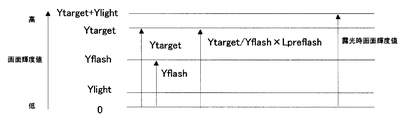
図8、9は、発光量計算2におけるフラッシュ発光量の求め方を説明するための図であり、図8は外光輝度が0すなわち暗黒時の撮影、図9は外光輝度がYlight時の撮影におけるフラッシュ発光量の求め方である。
【0029】
まず、図8に示す外光輝度が0であった場合を説明する。被写体を撮影したときの目標画面輝度値をYtarget、プリ発光露光したときの撮影画面の明るさであるプリ発光輝度値をYflashとする。また、フラッシュなしで露光した場合はYtargetだけ画面がアンダーに撮影されてしまう。そこで画面輝度をYtargetの値にするためには、Ytarget分だけフラッシュを発光すればよいことになる。
【0030】
また、図9に示す外光輝度がYlightであった場合を説明すると、最終的に画面輝度はYtarget+Ylightとなる。
【0031】
その後、ステップS104において決定されたフラッシュ発光量Lflashに基づいて、シャッター動作のタイミングとシンクロして発光量Lflashでフラッシュが発光して、CCDへの露光が行われる(ステップS108)。
【0032】
以上述べたように、露出時間の長い場合と短い場合とでフラッシュ発光量を求める手法を変更するようにし、露光時間が長い場合は外光測光時の誤差要因を排除するようにしたので、フラッシュ発光量ばらつきを低減することが可能となり、より安定した画面輝度の撮影を行うことができる。
【0033】
(その他の実施の形態)
上述した実施の形態の機能を実現するべく各種のデバイスを動作させるように、該各種デバイスと接続された装置或いはシステム内のコンピュータに対し、上記実施の形態の機能を実現するためのソフトウェアのプログラムコードを供給し、そのシステム或いは装置のコンピュータ(CPU或いはMPU)に格納されたプログラムに従って上記各種デバイスを動作させることによって実施したものも、本発明の範疇に含まれる。
【0034】
また、この場合、上記ソフトウェアのプログラムコード自体が上述した実施の形態の機能を実現することになり、そのプログラムコード自体は本発明を構成する。そのプログラムコードの伝送媒体としては、プログラム情報を搬送波として伝搬させて供給するためのコンピュータネットワーク(LAN、インターネット等のWAN、無線通信ネットワーク等)システムにおける通信媒体(光ファイバ等の有線回線や無線回線等)を用いることができる。
【0035】
さらに、上記プログラムコードをコンピュータに供給するための手段、例えばかかるプログラムコードを格納した記録媒体は本発明を構成する。かかるプログラムコードを記憶する記録媒体としては、例えばフレキシブルディスク、ハードディスク、光ディスク、光磁気ディスク、CD−ROM、磁気テープ、不揮発性のメモリカード、ROM等を用いることができる。
【0036】
また、コンピュータが供給されたプログラムコードを実行することにより、上述の実施の形態の機能が実現されるだけでなく、そのプログラムコードがコンピュータにおいて稼働しているOS(オペレーティングシステム)或いは他のアプリケーションソフト等と共同して上述の実施の形態の機能が実現される場合にもかかるプログラムコードは本発明の実施の形態に含まれることはいうまでもない。
【0037】
さらに、供給されたプログラムコードがコンピュータの機能拡張ボードやコンピュータに接続された機能拡張ユニットに備わるメモリに格納された後、そのプログラムコードの指示に基づいてその機能拡張ボードや機能拡張ユニットに備わるCPU等が実際の処理の一部又は全部を行い、その処理によって上述した実施の形態の機能が実現される場合にも本発明に含まれることはいうまでもない。
【0038】
なお、上記実施の形態において示した各部の形状及び構造は、何れも本発明を実施するにあたっての具体化のほんの一例を示したものに過ぎず、これらによって本発明の技術的範囲が限定的に解釈されてはならないものである。すなわち、本発明はその精神、又はその主要な特徴から逸脱することなく、様々な形で実施することができる。
【0039】
【発明の効果】
以上述べたように本発明によれば、露出時間に応じて、外光輝度値とプリ発光輝度値とを用いた第1の発光量を求めたり、プリ発光輝度値を用いた第2の発光量を求めたりするようにしたので、露光時間が長くなる場合に第2の発光量を求めるようにすれば、発光量のばらつきが発生するのを防止することができ、安定した画面輝度の撮影を行うことができる。
【図面の簡単な説明】
【図1】本実施の形態のデジタルカメラの概略構成を示すブロック図である。
【図2】EF処理部805の概略構成を示すブロック図である。
【図3】フラッシュ発光量が決定されるまでの処理を示すフローチャートである。
【図4】CCDデータから外光輝度値データへと変換する回路構成を示すブロック図である。
【図5】撮影画面を分割する様子を示す図である。
【図6】CCDデータから外光輝度値データへと変換する回路構成を示すブロック図である。
【図7】発光量計算1におけるフラッシュ発光量の求め方を説明するための図である。
【図8】発光量計算2におけるフラッシュ発光量の求め方を説明するための図である。
【図9】発光量計算2におけるフラッシュ発光量の求め方を説明するための図である。
【符号の説明】
202 エリア輝度値算出部
203 画面輝度値算出部
204 外光輝度値演算部
402 エリア輝度値算出部
403 画面輝度値算出部
801 撮像部
802 AF処理部
803 撮像制御部
804 AE処理部
805 EF処理部
806 画像処理部
807 データ書き込み部
901 調光演算選択部
902 プリ発光前処理部
903 プリ発光処理部
904 発光量演算部[0001]
BACKGROUND OF THE INVENTION
The present invention relates to an imaging device, a dimming method in the imaging device, a program, and a computer-readable storage medium.
[0002]
[Prior art]
Conventionally, in order to obtain an external light luminance value at the time of exposure, an external light luminance value before pre-emission is obtained by performing pre-emission on the CCD, and further pre-emission toward the subject to perform pre-emission exposure on the CCD. Is used to obtain the reflected luminance value of the subject in the shooting screen, and to determine the light emission amount that makes the subject appropriate from the external light luminance value and the reflected luminance value of the subject using the following equations (1) to (3). It is used.
Ylight = Ylightm × 2 ^ (Tvm−Tv) (1)
ΔEF = log2 ((Ytarget−Ylight) / (Yflash−Ylightm)) (2)
Lflash = Lpreflash × 2 ^ ΔEF Equation (3)
Tv: Exposure time during shooting
Tvm: Exposure time during pre-flash exposure
Ytarget: Screen target brightness value
Ylight: Brightness value of outside light during exposure
Ylightm: Brightness value before pre-flash
Yflash: Pre-flash luminance value
Lflash: Flash output during shooting
Lpreflash: Pre-flash amount [0003]
[Problems to be solved by the invention]
However, in the above calculation method, the light emission amount may not be accurately obtained when the exposure time is long. For example, when shooting a slow-synchronized portrait against a night scene with a long exposure time, the external light brightness value is corrected by correcting the pre-flash brightness value measured with a short exposure time due to the shutter release time lag problem. It is necessary to obtain the external light luminance value of the. Here, when the exposure time at the time of photographing is 8 seconds (Tv = -3) and the exposure time at the time of pre-flash exposure is 1/64 seconds (Tvm = 6), as can be seen from the above equation (1). The luminance value before pre-emission is multiplied by 2 ^ (6-(-3)) = 512. That is, when a photometric error occurs in the pre-emission luminance value obtained by the pre-emission pre-exposure, the error is multiplied by 512, so that the sensitivity to the error is increased, thereby causing variations in the emission amount. May occur.
[0004]
The present invention has been made in view of the above points, and an object of the present invention is to prevent a variation in light emission amount even when the exposure time is long.
[0005]
[Means for Solving the Problems]
An image pickup apparatus according to the present invention includes a light emission unit that emits light toward a subject, a pre-emission control unit that performs pre-emission before emission during shooting, and an external light metering unit that measures the brightness of the shooting screen before the pre-emission. And a pre-light metering means for measuring the brightness of the photographing screen during the pre-flash, an external light luminance value obtained by the external light metering means, and a pre-light luminance value obtained by the pre-light metering means. A first light emission amount calculating means for obtaining a light emission amount at the time of photographing; a second light emission amount calculating means for obtaining a light emission amount at the time of photographing using a pre-light emission luminance value obtained by the pre-light emission metering means; When the exposure time is shorter than the predetermined exposure time, the first light emission amount obtained by the first light emission amount calculating means is set. When the exposure time is longer than the predetermined exposure time, the second light emission amount is calculated. By the light emission amount calculation means And having a light emitting amount determination means for determining the use of the second light emission is fit.
[0006]
The light control method in the image pickup apparatus of the present invention measures the light emission procedure for emitting light toward the subject, the pre-emission control procedure for performing pre-emission before emission at the time of shooting, and the brightness of the shooting screen before the pre-emission. Ambient light metering procedure, a pre-flash metering procedure for metering the brightness of the shooting screen during the pre-flash, an ambient light brightness value obtained by the ambient light metering procedure, and a pre-flash brightness value obtained by the pre-flash metering procedure A first light emission amount calculation procedure for obtaining a light emission amount at the time of photographing using the above, a second light emission amount calculation procedure for obtaining a light emission amount at the time of photographing using the pre-light emission luminance value obtained by the pre-light emission metering procedure, When the exposure time at the time of shooting is shorter than the predetermined exposure time, the first light emission amount obtained by the first light emission amount calculation procedure is longer than the predetermined exposure time. Said second light emission A light emission amount determination procedure for determining the use of the second light emission amount obtained by the calculation procedure, and having a.
[0007]
The program of the present invention includes a light emitting unit that emits light toward a subject, a pre-emission control unit that performs pre-emission before light emission during shooting, and an external light metering unit that measures the brightness of the shooting screen before the pre-emission. A program for performing light control in an imaging apparatus having pre-light metering means for metering the brightness of a shooting screen at the time of pre-light emission, wherein the external light luminance value obtained by the external light metering means and the pre-light metering means A first light emission amount calculation process for obtaining a light emission amount at the time of photographing using the pre-light emission luminance value obtained by the light emission photometry means, and a light emission amount at the time of photographing using the pre-light emission luminance value obtained by the pre-light emission photometry means And the first light emission amount obtained by the first light emission amount calculation processing when the exposure time at the time of shooting is shorter than the predetermined exposure time. Is If longer than the exposure time are is characterized in that to execute a light emission amount determination processing for determining the use of the second light emission amount obtained by the second light emission amount calculation process, to the computer.
[0008]
The computer-readable storage medium of the present invention is characterized in that the program of the present invention is stored.
[0009]
DETAILED DESCRIPTION OF THE INVENTION
DESCRIPTION OF THE PREFERRED EMBODIMENTS Embodiments of an imaging device, a light control method in the imaging device, a program, and a computer-readable storage medium will be described below with reference to the drawings. Hereinafter, since the feature of the present invention is the light emission amount control during flash emission, the case of flash emission will be described.
[0010]
FIG. 1 is a block diagram showing a schematic configuration of a digital camera according to the present embodiment. In the figure,
[0011]
[0012]
An
[0013]
An
[0014]
FIG. 2 is a block diagram showing a schematic configuration of the
[0015]
Hereinafter, processing until the flash emission amount is determined will be described. FIG. 3 is a flowchart showing processing until the flash emission amount is determined. First, when the shutter is pressed (step S101), a determination is made based on the exposure time (step S102).
[0016]
In step S102, when the exposure time is shorter than the predetermined exposure time TvTH, pre-flash pre-exposure is performed (step S105). In the pre-flash pre-exposure, the CCD is exposed with an exposure time Tvm, and the data exposed to the CCD is A / D converted into CCD data.
[0017]
FIG. 4 shows a circuit configuration for converting CCD data into external light luminance value data. The
[0018]
Next, the screen luminance
Ylightm = Σ (Y (I, J) × W (I, J)) / Σ (W (IJ)) (4)
[0019]
Next, the external light luminance
Ylight = Ylightm × 2 ^ (Tvm−Tv) (5)
However, Tvm and Tv values are Apex values.
When the pre-flash pre-flash exposure operation ends (step S105), the pre-flash exposure operation is performed (step S106). In the pre-flash exposure, the flash is emitted with the light emission amount Lpreflash at the exposure time Tvm, and the CCD is exposed. The data exposed to the CCD is A / D converted and converted to CCD data in the same manner as the pre-light emission pre-exposure.
[0021]
FIG. 6 shows a circuit configuration for converting CCD data into external light luminance value data. The CCD data 401 obtained by the pre-flash exposure is sent to the area luminance
[0022]
Next, in the screen luminance value calculation unit 403, based on the luminance value Yf (I, J) for each area, the weight W (I, J) for each area shown in each area portion of FIG. 5 (I = 0 to 0). 5 and J = 0 to 5), the pre-emission luminance value Yflash is obtained by the following equation (6).
Yflash = Σ (Yf (I, J) × W (I, J)) / Σ (W (IJ)) (6)
[0023]
When the pre-flash exposure operation is completed (step S106), the light
[0024]
That is, the flash light emission amount Lflash for setting the screen brightness value to Ytarget can be obtained by the following equations (7) and (8).
ΔEF = log2 ((Ytarget−Ylight) / (Yflash−Ylightm)) (7)
Lflash = Lpreflash × 2 ^ ΔEF (8)
[0025]
Thereafter, based on the flash light emission amount Lflash determined in step S107, the flash is emitted with the light emission amount Lflash synchronized with the timing of the shutter operation, and the CCD is exposed (step S108).
[0026]
On the other hand, when the exposure time is equal to or longer than the predetermined exposure time TvTH in step S102, the pre-emission luminance value Yflash is obtained by the same operation as in step S106 (step S103).
[0027]
When the pre-flash exposure operation is completed (step S103), the light
ΔEF = log2 (Ytarget / Yflash) (9)
Lflash = Lpreflash × 2 ^ ΔEF (10)
[0028]
FIGS. 8 and 9 are diagrams for explaining how to calculate the flash light emission amount in the light
[0029]
First, the case where the external light luminance shown in FIG. 8 is 0 will be described. Let Ytarget be the target screen brightness value when the subject is shot, and Yflash be the pre-flash brightness value that is the brightness of the shooting screen when pre-flash exposure is performed. In addition, if the exposure is performed without a flash, the screen will be taken under Ytarget. Therefore, in order to set the screen brightness to the value of Ytarget, it is only necessary to emit flash for Ytarget.
[0030]
Further, in the case where the external light luminance shown in FIG. 9 is Ylight, the screen luminance is finally Ytarget + Ylight.
[0031]
Thereafter, based on the flash light emission amount Lflash determined in step S104, the flash is emitted with the light emission amount Lflash synchronized with the timing of the shutter operation, and the CCD is exposed (step S108).
[0032]
As described above, the flash emission amount calculation method is changed for long exposure time and short exposure time, and error factors during external light metering are eliminated when the exposure time is long. Variations in the amount of light emission can be reduced, and more stable screen brightness can be captured.
[0033]
(Other embodiments)
Software program for realizing the functions of the above-described embodiment for an apparatus or a computer in the system connected to the various devices so as to operate the various devices to realize the functions of the above-described embodiments. What was implemented by supplying the code and operating the various devices in accordance with a program stored in a computer (CPU or MPU) of the system or apparatus is also included in the scope of the present invention.
[0034]
In this case, the program code of the software itself realizes the functions of the above-described embodiments, and the program code itself constitutes the present invention. As a transmission medium for the program code, a communication medium (wired line or wireless line such as an optical fiber) in a computer network (LAN, WAN such as the Internet, wireless communication network, etc.) system for propagating and supplying program information as a carrier wave Etc.) can be used.
[0035]
Further, means for supplying the program code to the computer, for example, a recording medium storing the program code constitutes the present invention. As a recording medium for storing the program code, for example, a flexible disk, a hard disk, an optical disk, a magneto-optical disk, a CD-ROM, a magnetic tape, a nonvolatile memory card, a ROM, or the like can be used.
[0036]
Further, by executing the program code supplied by the computer, not only the functions of the above-described embodiments are realized, but also the OS (operating system) or other application software in which the program code is running on the computer. Needless to say, the program code is also included in the embodiment of the present invention even when the functions of the above-described embodiment are realized in cooperation with the above.
[0037]
Further, after the supplied program code is stored in the memory provided in the function expansion board of the computer or the function expansion unit connected to the computer, the CPU provided in the function expansion board or function expansion unit based on the instruction of the program code Needless to say, the present invention also includes the case where the functions of the above-described embodiment are realized by performing part or all of the actual processing.
[0038]
It should be noted that the shapes and structures of the respective parts shown in the above embodiments are merely examples of implementation in carrying out the present invention, and these limit the technical scope of the present invention. It should not be interpreted. That is, the present invention can be implemented in various forms without departing from the spirit or main features thereof.
[0039]
【The invention's effect】
As described above, according to the present invention, the first light emission amount using the external light luminance value and the pre-light emission luminance value is obtained according to the exposure time, or the second light emission using the pre-light emission luminance value. If the second light emission amount is obtained when the exposure time is long, it is possible to prevent variations in the light emission amount, and to capture a stable screen brightness. It can be performed.
[Brief description of the drawings]
FIG. 1 is a block diagram illustrating a schematic configuration of a digital camera according to an embodiment.
FIG. 2 is a block diagram illustrating a schematic configuration of an
FIG. 3 is a flowchart showing processing until a flash emission amount is determined.
FIG. 4 is a block diagram showing a circuit configuration for converting CCD data into external light luminance value data.
FIG. 5 is a diagram illustrating a state in which a shooting screen is divided.
FIG. 6 is a block diagram showing a circuit configuration for converting CCD data into external light luminance value data.
FIG. 7 is a diagram for explaining how to obtain a flash light emission amount in light
FIG. 8 is a diagram for explaining how to obtain a flash light emission amount in light
FIG. 9 is a diagram for explaining how to obtain a flash light emission amount in light
[Explanation of symbols]
202 Area luminance
Claims (5)
撮影時の発光前にプリ発光を行うプリ発光制御手段と、
前記プリ発光前の撮影画面の明るさを測光する外光測光手段と、
前記プリ発光時の撮影画面の明るさを測光するプリ発光測光手段と、
前記外光測光手段により得られる外光輝度値と前記プリ発光測光手段により得られるプリ発光輝度値とを用いて撮影時の発光量を求める第1の発光量演算手段と、
前記プリ発光測光手段により得られるプリ発光輝度値を用いて撮影時の発光量を求める第2の発光量演算手段と、
撮影時の露光時間が予め定められている露光時間よりも短い場合は前記第1の発光量演算手段により求められる前記第1発光量を、前記予め定められている露光時間よりも長い場合は前記第2の発光量演算手段により求められる前記第2発光量を用いることを決定する発光量決定手段と、を有することを特徴とする撮像装置。Light emitting means for emitting light toward the subject;
Pre-emission control means for performing pre-emission before emission during shooting,
Outside light metering means for metering the brightness of the shooting screen before the pre-flash,
Pre-flash metering means for metering the brightness of the shooting screen during the pre-flash,
A first light emission amount calculating means for obtaining a light emission amount at the time of photographing using an external light luminance value obtained by the external light photometric means and a pre-light emission luminance value obtained by the pre-light emission photometric means;
Second light emission amount calculating means for obtaining a light emission amount at the time of photographing using a pre-light emission luminance value obtained by the pre-light-emission metering means;
When the exposure time at the time of shooting is shorter than a predetermined exposure time, the first light emission amount obtained by the first light emission amount calculation means is set to be longer than the predetermined exposure time. An imaging apparatus comprising: a light emission amount determining unit that determines to use the second light emission amount obtained by the second light emission amount calculating unit.
撮影時の発光前にプリ発光を行うプリ発光制御手順と、
前記プリ発光前の撮影画面の明るさを測光する外光測光手順と、
前記プリ発光時の撮影画面の明るさを測光するプリ発光測光手順と、
前記外光測光手順により得られる外光輝度値と前記プリ発光測光手順により得られるプリ発光輝度値とを用いて撮影時の発光量を求める第1の発光量演算手順と、
前記プリ発光測光手順により得られるプリ発光輝度値を用いて撮影時の発光量を求める第2の発光量演算手順と、
撮影時の露光時間が予め定められている露光時間よりも短い場合は前記第1の発光量演算手順により求められる前記第1発光量を、前記予め定められている露光時間よりも長い場合は前記第2の発光量演算手順により求められる前記第2発光量を用いることを決定する発光量決定手順と、を有することを特徴とする撮像装置における調光方法。A flashing procedure that emits light toward the subject;
A pre-flash control procedure for pre-flash before flash during shooting,
Outside light metering procedure for metering the brightness of the shooting screen before the pre-flash,
A pre-flash metering procedure for metering the brightness of the shooting screen during the pre-flash,
A first light emission amount calculation procedure for obtaining a light emission amount at the time of photographing using an external light luminance value obtained by the external light metering procedure and a pre-light emission luminance value obtained by the pre-flash photometric procedure;
A second light emission amount calculation procedure for obtaining a light emission amount at the time of photographing using a pre-light emission luminance value obtained by the pre-light emission metering procedure;
When the exposure time at the time of shooting is shorter than a predetermined exposure time, the first light emission amount obtained by the first light emission amount calculation procedure is set. When the exposure time is longer than the predetermined exposure time, the first light emission amount is calculated. And a light emission amount determination procedure for determining to use the second light emission amount obtained by the second light emission amount calculation procedure.
前記外光測光手段により得られる外光輝度値と前記プリ発光測光手段により得られるプリ発光輝度値とを用いて撮影時の発光量を求める第1の発光量演算処理と、
前記プリ発光測光手段により得られるプリ発光輝度値を用いて撮影時の発光量を求める第2の発光量演算処理と、
撮影時の露光時間が予め定められている露光時間よりも短い場合は前記第1の発光量演算処理により求められる前記第1発光量を、前記予め定められている露光時間よりも長い場合は前記第2の発光量演算処理により求められる前記第2発光量を用いることを決定する発光量決定処理と、をコンピュータに実行させることを特徴とするプログラム。Light emission means for emitting light toward the subject, pre-light emission control means for performing pre-light emission before light emission at the time of shooting, external light metering means for measuring the brightness of the shooting screen before the pre-light emission, and at the time of the pre-light emission A program for performing light control in an image pickup apparatus having pre-light metering means for metering the brightness of a shooting screen,
A first light emission amount calculation process for obtaining a light emission amount at the time of photographing using an external light luminance value obtained by the external light metering unit and a pre-light emission luminance value obtained by the pre-light metering unit;
A second light emission amount calculation process for obtaining a light emission amount at the time of photographing using a pre-light emission luminance value obtained by the pre-light-emission metering means;
When the exposure time at the time of shooting is shorter than a predetermined exposure time, the first light emission amount obtained by the first light emission amount calculation process is set to be longer than the predetermined exposure time. A program for causing a computer to execute a light emission amount determination process for determining that the second light emission amount obtained by the second light emission amount calculation process is used.
Priority Applications (1)
| Application Number | Priority Date | Filing Date | Title |
|---|---|---|---|
| JP2002081441A JP3970071B2 (en) | 2002-03-22 | 2002-03-22 | Imaging apparatus, dimming method in imaging apparatus, program, and computer-readable storage medium |
Applications Claiming Priority (1)
| Application Number | Priority Date | Filing Date | Title |
|---|---|---|---|
| JP2002081441A JP3970071B2 (en) | 2002-03-22 | 2002-03-22 | Imaging apparatus, dimming method in imaging apparatus, program, and computer-readable storage medium |
Publications (3)
| Publication Number | Publication Date |
|---|---|
| JP2003280061A JP2003280061A (en) | 2003-10-02 |
| JP2003280061A5 JP2003280061A5 (en) | 2005-09-08 |
| JP3970071B2 true JP3970071B2 (en) | 2007-09-05 |
Family
ID=29230066
Family Applications (1)
| Application Number | Title | Priority Date | Filing Date |
|---|---|---|---|
| JP2002081441A Expired - Fee Related JP3970071B2 (en) | 2002-03-22 | 2002-03-22 | Imaging apparatus, dimming method in imaging apparatus, program, and computer-readable storage medium |
Country Status (1)
| Country | Link |
|---|---|
| JP (1) | JP3970071B2 (en) |
Families Citing this family (3)
| Publication number | Priority date | Publication date | Assignee | Title |
|---|---|---|---|---|
| CN100420281C (en) * | 2004-12-28 | 2008-09-17 | 佳能株式会社 | Image sensing apparatus and image sensing apparatus control method |
| JP2009276560A (en) * | 2008-05-14 | 2009-11-26 | Ricoh Co Ltd | Imaging apparatus and imaging method |
| US11642743B2 (en) | 2017-11-07 | 2023-05-09 | Hamamatsu Photonics K.K. | Laser processing method, and laser processing device |
-
2002
- 2002-03-22 JP JP2002081441A patent/JP3970071B2/en not_active Expired - Fee Related
Also Published As
| Publication number | Publication date |
|---|---|
| JP2003280061A (en) | 2003-10-02 |
Similar Documents
| Publication | Publication Date | Title |
|---|---|---|
| JP5917258B2 (en) | Image processing apparatus and image processing method | |
| JP4574185B2 (en) | Image pickup apparatus and flash device control method | |
| TWI386042B (en) | Digital camera device and its brightness correction method | |
| JP2008187317A (en) | Photographing device and control method thereof, and program | |
| JP2011128536A (en) | Imaging apparatus and control method therefor | |
| WO2012093519A1 (en) | Imaging device and light emission amount control method | |
| JP6303304B2 (en) | camera | |
| JP2012235377A (en) | Image processing apparatus, image processing method, and program | |
| JP6465671B2 (en) | LIGHT CONTROL DEVICE, ITS CONTROL METHOD, CONTROL PROGRAM, AND IMAGING DEVICE | |
| JP2011039449A (en) | Imaging apparatus and control method thereof | |
| JP5898509B2 (en) | Imaging apparatus, control method therefor, program, and storage medium | |
| JP5225137B2 (en) | Imaging apparatus, image processing method, and program | |
| JP2011119944A (en) | Imaging apparatus and method of controlling the same | |
| JP3970071B2 (en) | Imaging apparatus, dimming method in imaging apparatus, program, and computer-readable storage medium | |
| JP6231814B2 (en) | EXPOSURE DETERMINING DEVICE, IMAGING DEVICE, CONTROL METHOD, AND PROGRAM | |
| JP6214229B2 (en) | Imaging apparatus, imaging apparatus control method, image processing apparatus, and image processing method | |
| JP2005354199A (en) | Imaging apparatus and control method thereof | |
| JP2011135378A (en) | Imaging device and imaging method | |
| JP2006171315A (en) | Stroboscope controller, stroboscope control program, and stroboscope control method | |
| JPH11252451A (en) | Image-pickup device and computer-readable storage medium thereof | |
| JP2016085248A (en) | Exposure computation device | |
| JP2002277920A (en) | Exposure control method and photographing device | |
| JP2003348603A (en) | Electronic camera | |
| JPH1195278A (en) | Image pickup device | |
| JP6916414B2 (en) | Light emission control device, imaging device and lighting device |
Legal Events
| Date | Code | Title | Description |
|---|---|---|---|
| A521 | Request for written amendment filed |
Free format text: JAPANESE INTERMEDIATE CODE: A523 Effective date: 20050317 |
|
| A621 | Written request for application examination |
Free format text: JAPANESE INTERMEDIATE CODE: A621 Effective date: 20050317 |
|
| A977 | Report on retrieval |
Free format text: JAPANESE INTERMEDIATE CODE: A971007 Effective date: 20070226 |
|
| A131 | Notification of reasons for refusal |
Free format text: JAPANESE INTERMEDIATE CODE: A131 Effective date: 20070306 |
|
| A521 | Request for written amendment filed |
Free format text: JAPANESE INTERMEDIATE CODE: A523 Effective date: 20070423 |
|
| TRDD | Decision of grant or rejection written | ||
| A01 | Written decision to grant a patent or to grant a registration (utility model) |
Free format text: JAPANESE INTERMEDIATE CODE: A01 Effective date: 20070522 |
|
| A61 | First payment of annual fees (during grant procedure) |
Free format text: JAPANESE INTERMEDIATE CODE: A61 Effective date: 20070605 |
|
| R150 | Certificate of patent or registration of utility model |
Free format text: JAPANESE INTERMEDIATE CODE: R150 |
|
| FPAY | Renewal fee payment (event date is renewal date of database) |
Free format text: PAYMENT UNTIL: 20110615 Year of fee payment: 4 |
|
| FPAY | Renewal fee payment (event date is renewal date of database) |
Free format text: PAYMENT UNTIL: 20120615 Year of fee payment: 5 |
|
| FPAY | Renewal fee payment (event date is renewal date of database) |
Free format text: PAYMENT UNTIL: 20120615 Year of fee payment: 5 |
|
| FPAY | Renewal fee payment (event date is renewal date of database) |
Free format text: PAYMENT UNTIL: 20130615 Year of fee payment: 6 |
|
| LAPS | Cancellation because of no payment of annual fees |