JP3969974B2 - Patient transporter and stretcher for patient transport - Google Patents
Patient transporter and stretcher for patient transport Download PDFInfo
- Publication number
- JP3969974B2 JP3969974B2 JP2001216168A JP2001216168A JP3969974B2 JP 3969974 B2 JP3969974 B2 JP 3969974B2 JP 2001216168 A JP2001216168 A JP 2001216168A JP 2001216168 A JP2001216168 A JP 2001216168A JP 3969974 B2 JP3969974 B2 JP 3969974B2
- Authority
- JP
- Japan
- Prior art keywords
- biological information
- patient
- stretcher
- pressure
- fluid
- Prior art date
- Legal status (The legal status is an assumption and is not a legal conclusion. Google has not performed a legal analysis and makes no representation as to the accuracy of the status listed.)
- Expired - Fee Related
Links
Images


Description
【0001】
本発明は、患者搬送具及び患者搬送用の担架に関するものであり、特に、緊急時や災害時に使用される担架やストレッチャー等に関するものである。
【0002】
【従来の技術】
従来、緊急時及び災害時の救急システムにおける応急処置は、救急救命士等が、患者の意識、呼吸、心拍の確認を行い、119番通報し、その聞に気道確保や人工呼吸等を行い応急処置を行っていた。初期の応急処置により、救命率を向上させることができる。一方、救急隊員が現場にかけつけると、救急救命士等は、確認した情報を伝えたり、現在の状況を客観的に伝え、患者を担架やストレッチャーの上に乗せて救急車まで搬送している。
【0003】
他方、従来より、人体の健康状態を測定する技術がある。例えば、特開平10−229973号公報(従来技術1)には、圧電センサをマットに内蔵して人体の振動を検知し脈拍、血圧等を計測する生体モニタ装置が開示されている。また、実開昭58−188008号公報(従来技術2)には、被検者の下に敷かれたエアマット内の圧力変化を電気信号として検出し、被検者の呼吸を計測する呼吸モニターが開示されている。しかしながら、これらの従来技術1、2は、救急システムにおいて用いられる点は開示されていない。
【0004】
【発明が解決しようとする課題】
従来の救急システムにおいては、患者を救急車に乗せるまでの間、意識や呼吸、心拍の確認を迅速且つ正確に行なうことは困難である。救急車内では、心電図や酸素マスク、止血用の器具等の応急処置ができる器具が揃っているが、救急隊員が現場に到着するまでの時間は、患者や負傷者の状態を客観的に把握するのは難しい。
【0005】
本発明は、このような問題点を解決するためになされたものであり、患者を搬送する場合にも生体情報を計測できる患者搬送具及び患者搬送用の担架を提供することを目的とする。
【0006】
【課題を解決するための手段】
本発明に係る患者搬送具は、患者を乗せて搬送する患者搬送具であって、生体情報を検出する生体情報検出手段(例えば、本実施の形態におけるエアマット1及び圧力センサ55)と、前記生体情報検出手段により検出された生体情報を表示する生体情報表示手段(例えば、本実施の形態における操作・表示器28)と、前記生体情報を無線通信によって送信する生体情報送信手段とを備え、前記生体情報検出手段は、患者を乗せる荷台部に配置され、流体が封入された流体封入体と、当該流体封入体と導圧管を通じて接続された圧力センサとを有し、前記患者搬送具に患者が乗せられたことを検出し、生体情報の検出処理を開始するとともに、前記導圧管は、その途中部において着脱可能であり、前記流体封入体に対して、流体の封入量を調整する調整手段を有するものである。
【0007】
このような構成により、患者を搬送する場合にも生体情報を計測でき、また、流体封入体と導圧管とを分離することができることにより、汚れ易い荷台を別に取り扱うことができ、また、救急の場合に、生体情報の検出処理を開始するためのスイッチ操作を行う手間を省くことができ、さらにまた、患者の生体情報を遠隔において認識することができる。
【0008】
また、前記患者搬送具は、担架であって、当該担架は、その担ぎ棒の筐体中に収容されている前記生体情報表示手段と、当該生体情報表示手段に対して電力を供給する充電池と、を有するようにしてもよい。このような構成により、患者を搬送する場合にも生体情報を計測でき、また、充電池を常に充電状態に保つことができる。
【0009】
また、前記患者搬送具は、ストレッチャーであって、当該ストレッチャーは、その引き手部分に配置された前記生体情報表示手段と、当該生体情報表示手段に対して電力を供給する充電池と、を有するようにしてもよい。このような構成により、患者を搬送する場合にも生体情報を計測でき、また、充電池を常に充電状態に保つことができる。
【0010】
また、前記患者搬送具は、担架であって、当該担架は、患者を乗せる荷台部と、当該荷台部と分離可能な担ぎ棒とを備え、前記荷台部は、流体が封入された流体封入体を有し、前記担ぎ棒は、前記流体封入体と導圧管を介して接続された圧力センサと、前記圧力センサによって検出された生体情報を表示する生体情報表示手段とを有し、前記導圧管は、その途中部において着脱可能とするものである。
【0011】
このような構成により、患者を搬送する場合にも生体情報を計測でき、また、流体封入体と導圧管とを分離することができることにより、汚れ易い荷台部を、担ぎ棒から取り外して丸洗いすることができる。
【0016】
【発明の実施の形態】
最初に、本発明を想到するに至った過程について説明する。救急システムにおいて、怪我や病気が発生したときに、まずは早急にその病状を知ることが肝心である。そのため、駅舎、学校、船等の公共場所で、救急車が現場に到着するまでの間に、誰でも容易に患者の状態を計測可能な生体モニター装置があると良い。例えば、公共場所に設置される救急用担架にモニター装置を搭載すれば良い。しかし、担架は人力で担いで使用するものであるため、モニター装置はきわめて小型軽量であることが要求される。また、非使用時には、丸められたり折りたたまれたりして収容箱に保管されるので、そのような取り扱いに耐えることが要求される。さらに、担架の荷台部分は使用によって汚れるので、担ぎ棒から取り外して丸洗いできることが望ましい。
【0017】
例えば、従来技術1に記載の技術を担架に適用しようとした場合、荷台に圧電センサを配置すると共に電気信号線を配置する必要がある。しかし、荷台が布製であるために患者を乗せたとき、あるいは丸めて収容箱に収容するときに、圧電センサや電気信号線に大きな力が加わりやすく、圧電センサの破壊や電気信号線の断線を招いてしまうという問題がある。
【0018】
また、従来技術2に記載の技術を担架に適用しようとした場合、計測器の筐体を担架と共に持ち歩く必要があり、救急作業の邪魔になるので、実用的ではない。
【0019】
本発明の実施の形態に開示した担架は、その一部に生体情報計測用のエアマットが装着されている。そして、担架の担ぎ棒に生体情報表示装置を設けている。さらに、エアマットが装着されている荷台と、生体情報表示装置が設けられた担ぎ棒は着脱可能である。さらに、エアマットと生体情報表示装置とは、導圧管により接続されている。その導圧管が途中部において着脱可能な構造を有している。
【0020】
このような構成により、本発明の実施の形態に開示した好適な患者搬送具は、使用時には軽量で救急作業の妨げにならず、非使用時には折りたたんで収納することが可能な担架を提供することができる。
【0021】
図1は、本発明にかかる患者搬送具の全体イメージ図である。図1において、(a)は、担架タイプの患者搬送具であり、(b)は、ストレッチャータイプの患者搬送具である。
【0022】
患者を載置する荷台の一部には、エアマット1が装着されている。このエアマット1は、圧力の変動により、生体情報を得るものであり、流体封入体の一例として開示されている。この流体封入体は、袋に水又は空気等の流体が封入されている。流体封入体は、パッド状であっても、複数個のブロックに分離されたシート状のものであってもよい。
【0023】
本発明にかかる患者搬送具には、生体情報表示装置2が設けられている。この生体情報表示装置2は、担架の担ぎ棒やストレッチャーの引き手に設けられた筐体中に収納されている。この生体情報表示装置2は、導圧管を介してエアマット1からの圧力変動を検出し、その生体情報を表示する機能等を有する。エアマット1に患者が載置され、患者の重量により圧力が加えられることにより、圧力変動の計測を開始するようにしてもよい。
【0024】
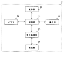
図2にこの生体情報表示装置2の構成を示す。図に示されるように、生体情報表示装置2は、制御部21、表示部22、操作部23、メモリ24、信号処理部25及び検出部26を備えている。
【0025】
制御部21は、マイクロコンピュータ等により構成されており、所定の制御プログラムにより所定の処理を実行する。
【0026】
表示部22は、心拍数、呼吸数等の生体情報を表示する。この表示部22は、液晶パネル、プラズマディスプレイパネル等により構成されており、担架の担ぎ棒やストレッチャーの引き手の筐体より外側に露出し、外部よりその表示内容が視認できるよう構成されている。また、表示部22は、当該担ぎ手、引き手の筐体の一部又は全部が、透明又は半透明であれば、筐体の外側に露出していなくともよい。
【0027】
操作部23は、ボタン、スイッチ、キーパッド等により構成され、生体情報表示装置2を操作するための指示を入力するものである。例えば、操作部23を操作することによって、表示部22における表示の形態を変更したり、電源のオンオフを切り替えたりすることができる。表示部22と操作部23は、一体的に図3に示されるような操作・表示器28として構成してもよい。
【0028】
メモリ24は、検出部26において検出された患者の生体情報であって、信号処理された生体情報や測定時刻情報等の情報を記憶する。
【0029】
信号処理部25は、検出部26において検出された患者の生体情報に対して信号処理を行なう機能を有する。具体的には、信号処理部25は、分離する信号の周波数帯域に対応したバンドパスフィルタと増幅器により信号処理する。このバンドパスフィルタは、心拍、呼吸、いびき発声等の抽出すべき信号の周波数帯域に合致した周波数の信号のみ通過させる。
【0030】
検出部26は、患者の生体情報を検出する。具体的には、エアマット1の圧力変動を導圧管を通じて検出する圧力センサがこの検出部26に相当する。この検出部26の一例である圧力センサは、マイク付きにして音声を感知し、いびきのありなしを検出するようにしてもよい。
【0031】
図3は、操作・表示器28の外観図である。この例では、表示部22に、心拍数と呼吸数が表示されている。また、操作部23には、計測ボタン、リセットボタン、電源ボタンが設けられている。計測ボタンを押下すると、計測を開始し、リセットボタンを押下するとリセット処理を開始し、電源ボタンを押下すると、電源のオン・オフが切り替えられる。
【0032】
ここで、図4及び図5を用いて、信号処理部25における信号の分離処理について詳述する。例えば、呼吸の場合、個人によって異なるが、呼吸周期を決めておき、その周波数帯の信号のみを取り出し呼吸信号とする。呼吸に関する通過域は、0.05〜1Hzである。心拍の場合、約1秒間隔のスパイク状信号であり、通過域は、2〜10Hz程度である。心拍数及び呼吸数を示すグラフを図4に示す。
【0033】
音声/いびきは、高い周波数の領域であり、30〜200Hzである。これらの周波数領域の幅は、データ管理端末で設定・変更可能であり、個体差により誤差が生じないようにする。音声/いびきの有無及び体動の有無を示すグラフを図5に示す。
【0034】
体動は、大きな圧力変動となって現れる。絶対値が大きいため、広域な周波数帯において圧力変動が生じる。従って、呼吸/心拍/音声等の組み合わせに基づき、体動を総合的に判断する。体動は、主に信号の振幅より判断する。
【0035】
生存しているかどうかは、例えば、呼吸、心拍の信号が存在するかというファクタに基づき判断する。主に信号のパワーに基づき判断する。場合によっては、エアマット1内の絶対(ゲージ)圧力に基づき判断する。
【0036】
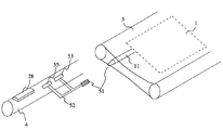
続いて、患者搬送具の詳細な構成について、図を用いて説明する。図6は、患者を載置した状態において、情報から患者搬送具を見た図である。この例では、患者搬送具は担架である。図7は、図6のA−A断面を示す図である。図8は、図6のB−B断面の拡大図である。
【0037】
図6に示されるように、担架は、基本的に荷台3、担ぎ棒4により構成されている。荷台3は、一枚の帆布の一端と他端とを縫合してエンドレスベルト形状に形成したものである。図7に示されるように、このエンドレスベルトの輪の中に2本の担ぎ棒4、エアマット1及び導圧管11を配置し、上布31と下布32とを縫合してこれらの構成を挟み込み固定してある。担ぎ棒4の近傍を長手方向に沿って縫合し、担ぎ棒4を長手方向に引っ張ったときに荷台から分離可能としている。エアマット1は、可撓性を有する2枚の合成樹脂製のシートの周囲を熱溶著して気密に形成したものである。
【0038】
導圧管11は、可撓性を有する合成樹脂製のチューブからなる。導圧管11の一端がエアマット1内部に連通するように固定され、荷台3の上布31と下布32との間を通して外部に導出されている。導圧管11の他端に着脱式継ぎ手の一方が設けられており、担ぎ棒4に固定された着脱式継ぎ手の他方に対して着脱自在となっている。
【0039】
図8に示されるように、担ぎ棒4は、中空の金属管で形成されており、その内部には回路基板56、操作・表示器28、三叉導圧管52、空気ポンプ53および電動モータ54が固定されている。担ぎ棒4の一端にねじ蓋が形成されており、これを外すと担ぎ棒4内部の電池ボックスに収納された乾電池57を交換できる。回路基板56には、マイクロコンピュータ等が載置されている。操作・表示器28は、窓27を通じて外側に露出している。
【0040】
一般に市販されている乾電池のうち、最も形状の大きい単一電池でも外径約35mm、長さ約60mmであり、乾電池の長手方向を担ぎ棒4の長手方向に一致させて直列に配置すれば、担ぎ棒4の外径を人手で握るのに適した太さに形成できる。
【0041】
空気ポンプ53は、例えば特表2000−517232号公報の図3及びその説明に開示されているものと同様の非可逆低圧ダイアフラムポンプである。ダイアフラムを往復運動させることにより空気を送出する。この方式のポンプは小型化に適しており、本実施の形態のように直径40mm程度の担ぎ棒4の内部にも収容可能である。逆止弁を内蔵しているので空気がポンプヘ逆流して気圧低下を招くことは無い。ポンプに外気を供給するために担ぎ棒4に空気孔が形成されている。
【0042】
尚、この特表2000−517232号公報の図3及びその説明に開示されている構造の空気ポンプでなくとも、本願明細書の図9に示す構造の空気ポンプであってもよい。図9に示す空気ポンプは、円筒カム62を用いてモータ61の回転を直線運動に変換し、ダイヤフラムユニット63を動作させている。これらのモータ61、円筒カム62及びダイヤフラムユニット63は、担ぎ棒4の内径に収まる大きさのものを選択している。尚、円筒カム62の具体的な構成例は、「新編機械の素」機械の素復刊委員会編(発行所 理工学社)1969年7月10日第4版に開示されている。
【0043】
その他、回転モータを用いずに、往復動型のソレノイドを用いて、空気ポンプを構成するようにしてもよい。
【0044】
エアマット1の内圧は、無負荷状態で大気圧よりも若干高い程度(すなわちエアマットが膨らむ程度)でよい。エアマット1の内容積もきわめてわずか(膨らんだ状態で厚さ10mm程度)でよい。空気ポンプ53は、電力消費量が比較的に多いが、エアマット1の内容積が少なく稼動時間が短いので、電源として乾電池を用いても十分対応可能である。即ち、すぐに電池がなくなってしまうということはない。
【0045】
また、担ぎ棒4の内部に合成樹脂性の三叉導圧管52が設けられて、着脱式継ぎ手51と圧力センサ55と空気ポンプ53とを接続している。
【0046】
エアマット1、導圧管11、着脱式継ぎ手51、三叉導圧管52、圧力センサ55および空気ポンプ53が互いに連通すると共に気密に閉じた空間を形成しており、エアマット1に外力を加えたとき、内部の気圧変化が導圧管11、着脱式継ぎ手51および三叉導圧管52を介して圧力センサ55に伝わる。
【0047】
回路基板56に載置された圧力センサ55は、市販のエレクトレット・コンデンサ・マイクロフォンを利用したものを用いることができる。静電容量式のマイクロフォンは、ダイアフラムのバックチャンバーの容積と空気抜き孔の大きさを適宜調節することで、最適な周波数感度特性を得ることが容易である。
【0048】
圧力センサ55については、例えば特許公報第2763896号に従来技術として記載されている図3の構成を採用できる。また、過大負荷が加えられたときでも、電極によってダイアフラムが支持されダイアフラムの変位が所定量以上に増加しないので、ダイアフラムの破壊に至らない。即ち、患者を荷台3に乗せたときに突発的に発生する圧力によっても破壊されない。
【0049】
次に、図10を用いて、本発明の実施の形態にかかる患者搬送具の使用方法を担架を例に挙げ説明する。まず、患者を担架に乗せる(S1001)。そして、操作・表示器28の電源スイッチを入れる(S1002)。
【0050】
電源スイッチを入れることに応じて、自動的に電動モータ54が回転し空気ポンプ53からエアマット1ヘ空気が送られ、圧力センサ55により検出された内圧が適正値になったとき電動モータ54が停止する(S1003)。
【0051】
計測結果が操作・表示器28に表示される(S1004)。そして、患者を降ろした後、着脱継ぎ手51を外すと導圧管11を通してエアマット1内の空気が抜け、荷台3は折りたたみやすくなる(S1005)。
【0052】
図10に示すフローのうち、ステップS1003及びステップS1004は、回路基板56上に設けられたマイクロコンピュータからなる制御部21のプログラムにより実施される。その処理フローを図11に示す。
【0053】
図11において、まず、制御部21は、電源がオン状態にあるか否かを判定する(S1101)。判定の結果、電源がオン状態である場合には、電動モータ54が回転し空気ポンプ53からエアマット1ヘ空気が送られる(S1102)。続いて、制御部11は、圧力センサ55により検出された内圧が所定値以上かどうかを判定する(S1103)。判定の結果、所定値以上である場合には、電動モータ54を停止し、これに伴い、空気ポンプ53も停止する。
【0054】
そして、圧力センサ55によるエアマット1の圧力変動を検出することによって、生体情報の測定を開始する(S1104)。そして、その計測結果を操作・表示部28に表示する(S1105)。
【0055】
ここで、図12及び図13に、着脱式継ぎ手の着脱時の様子を示す。図12に示す着脱式継ぎ手51においては、エアマット1側の着脱式継ぎ手51がクリック式の栓オス構造を有し、担ぎ棒4側の着脱式継ぎ手がクリック式の栓メス構造を有する。着脱は、エアー取り組み口を介して行い、双方に設けられた栓を嵌合させることにより行なわれる。この着脱構造は、一般的なガス栓と同様な構造を有する。
【0056】
図13に着脱構造の別の例を示す。この例では、エアマット1に2本の導圧管12、13が接続され、各々に着脱式継ぎ手58、59を有している。そして、各々の着脱式継ぎ手58、59は導圧管を介して空気ポンプ53及び圧力センサ55と接続されている。
【0057】
図14は、生体情報表示装置2に代えて、検出した生体情報を信号処理し、その信号を無線通信より他の場所に設置された生体情報表示装置等に送信する生体情報送信装置2aを設置した場合の構成図である。この生体情報送信装置2aは、検出部201、バンドパスフィルタ202、203、204、増幅器205、206、207、無線通信処理部208、アンテナ209を備えている。
【0058】
検出部201は、エアマット1の圧力変動を検出するものであり、例えば、圧力センサである。バンドパスフィルタ202、203、204は、検出部201から出力された信号が入力される。この信号は、圧力変動に応じた信号である。このバンドパスフィルタ202、203、204は、各々心拍、呼吸、いびきに対応した周波数帯域を通過させるものである。この例では、3つのバンドパスフィルタを示したが、これに限らず、2つ以上の任意の数のバンドパスフィルタを用いるようにしてもよい。尚、この例では、バンドパスフィルタとしてアナログフィルタが用いられているが、これに限らず、検出信号をA/D変換した後にデジタルフィルタにより信号を分離するようにしてもよい。増幅器205、206、207は、各々のバンドパスフィルタ202、203、204に接続され、各々のフィルタを通過した信号を増幅する。無線通信処理部208は、増幅器205、206、207により増幅された各信号を入力し、無線により出力するための変調処理等を実行している。アンテナ209は、無線通信処理部208からの出力信号を電波信号に変換し、送信する機能を有する。
【0059】
この生体情報送信装置2aより送信された信号は、生体情報表示装置に送信され、当該生体情報表示装置において、生体情報を表示し、管理する。例えば、この生体情報表示装置は、救急車、救急センター、病院等に設置される。
【0060】
尚、エアマット1は、内庄調整ができる構成を有しており、患者を荷台3に乗せる前に初期値を設定する内圧調整機能(調節用ポンプ)を有している。
【0061】
また、電源は、充電池にしても良い。さらに、担ぎ棒4の表面に充電用端子を露出させておき、収容箱に格納された状態で収納箱側の電源端子と担ぎ棒の充電端子とが接触するように構成すれば、担ぎ棒の充電池を常に充電状態に保つことが可能である。エアマット1に空気を送るための電動ポンプの代わりに、手動ポンプやスプレー缶方式の空気充填器を使用してもよい。
【0062】
さらに、計測結果を表示するだけでなく、無線で所定の場所に送信しても良い。近年、「ケータイ・チップ」と呼ばれる、携帯電話の通信機能を7mm角程度の基板上に集約した集積回路が開発されており、担ぎ棒4の内部の回路基板に搭載可能である。救急病院や救急車の電話番号を予めメモリに登録しておけば、計測結果が電話回線を通じて送信される。
【0063】
以上のように、救急時の搬送用の担架等に生体情報を計測し表示する表示装置を備えたことにより、救急車両に搬送しなければ生体情報が把握できないということはなくなり、客観的に現在の状況を判断することができる。このように緊急事態において、救急車両に到着するまでの間に生体情報が把握でき、応急処置を行うことができるため、従来ならば救急車両まで行えなかった応急処置を即座に行うことができる。これにより、患者の人命救助はもとより、救急隊員の負担軽滅にもなる。
【0064】
また、担架等にエアマットを装着することにより、取り外しが容易に行え、これにより洗うなどのメンテナンスが容易となり、収納についてもコンパクトに行える。という効果がある。
【0065】
本発明により、患者を搬送する場合にも生体情報を計測できる患者搬送具及び患者搬送用の担架を提供することができる。
【図面の簡単な説明】
【図1】本発明にかかる患者搬送具のイメージ図である。
【図2】本発明にかかる生体情報表示装置の構成図である。
【図3】本発明にかかる生体情報表示装置の表示操作器を示す図である。
【図4】本発明にかかる生体情報表示装置における信号処理を説明するための図である。
【図5】本発明にかかる生体情報表示装置における信号処理を説明するための図である。
【図6】本発明にかかる患者搬送具の詳細構成を示す図である。
【図7】本発明にかかる患者搬送具の詳細構成を示す図である。
【図8】本発明にかかる患者搬送具の詳細構成を示す図である。
【図9】本発明にかかる患者搬送具の詳細構成を示す図である。
【図10】本発明にかかる患者搬送具の使用方法を示すフローチャートである。
【図11】本発明における生体情報表示装置の処理の流れを示すフローチャートである。
【図12】本発明にかかる患者搬送具における着脱構造を示す図である。
【図13】本発明にかかる患者搬送具における着脱構造を示す図である。
【図14】本発明における生体情報表示装置の構成を示す図である。
【符号の説明】
1 エアマット 2 生体情報表示装置 3 荷台
4 担ぎ棒[0001]
The present invention relates to a patient carrier and a patient carrier stretcher , and more particularly to a stretcher, stretcher, and the like used in an emergency or disaster.
[0002]
[Prior art]
Conventionally, emergency treatment in emergency systems in emergency and disaster has been performed by emergency medical technicians, etc., confirming the patient's awareness, breathing, and heart rate, calling 119, and securing the airway and artificial respiration, etc. I was taking treatment. The first-aid treatment can improve the lifesaving rate. On the other hand, when an ambulance crew visits the site, paramedics and the like convey the confirmed information, objectively convey the current situation, and transport the patient to an ambulance on a stretcher or stretcher.
[0003]
On the other hand, there is a conventional technique for measuring the health condition of the human body. For example, Japanese Patent Laid-Open No. 10-229973 (Prior Art 1) discloses a living body monitor device that incorporates a piezoelectric sensor in a mat to detect vibrations of a human body and measure a pulse, blood pressure, and the like. Japanese Utility Model Publication No. 58-188008 (prior art 2) discloses a respiratory monitor that detects a change in pressure in an air mat placed under a subject as an electrical signal and measures the respiration of the subject. It is disclosed. However, these prior arts 1 and 2 are not disclosed for use in an emergency system.
[0004]
[Problems to be solved by the invention]
In a conventional emergency system, it is difficult to quickly and accurately confirm consciousness, breathing, and heartbeat until the patient is put in an ambulance. In the ambulance, there are equipment for emergency treatment such as an electrocardiogram, oxygen mask, and hemostasis equipment, but the time until the emergency personnel arrive at the scene objectively grasps the state of the patient and the injured. Is difficult.
[0005]
The present invention has been made to solve such problems, and an object of the present invention is to provide a patient transport tool and a patient transport stretcher capable of measuring biological information even when a patient is transported.
[0006]
[Means for Solving the Problems]
The patient transport device according to the present invention is a patient transport device for transporting a patient, and is a biometric information detecting means for detecting biometric information (for example, the air mat 1 and the
[0007]
With such a configuration, biological information can be measured even when a patient is transported, and since the fluid enclosure and the pressure guiding tube can be separated, it is possible to separately handle a platform that is easily contaminated, In this case, it is possible to save the trouble of performing a switch operation for starting the biometric information detection process, and it is possible to remotely recognize the biometric information of the patient.
[0008]
The patient carrier is a stretcher, and the stretcher is a rechargeable battery that supplies electric power to the biological information display means and the biological information display means housed in the housing of the support rod. You may make it have. With such a configuration, biological information can be measured even when a patient is transported, and the rechargeable battery can be always kept in a charged state.
[0009]
Further, the patient carrier is a stretcher, and the stretcher has the biometric information display means arranged at the handle portion, a rechargeable battery for supplying power to the biometric information display means, You may make it have. With such a configuration, biological information can be measured even when a patient is transported, and the rechargeable battery can be always kept in a charged state.
[0010]
Further, the patient carrier is a stretcher, and the stretcher includes a loading platform portion on which a patient is placed, and a support rod that can be separated from the loading platform portion, and the loading platform portion is a fluid enclosure in which a fluid is sealed. The support rod includes a pressure sensor connected to the fluid enclosure via a pressure guiding tube, and a biological information display means for displaying biological information detected by the pressure sensor, and the pressure guiding tube Is detachable in the middle part.
[0011]
With such a configuration, biological information can be measured even when a patient is transported, and the fluid enclosure and the pressure guiding tube can be separated, so that the easily loaded platform can be removed from the carrying rod and washed. Can do.
[0016]
DETAILED DESCRIPTION OF THE INVENTION
First, the process that led to the present invention will be described. When an injury or illness occurs in an emergency system, it is important to know the medical condition as soon as possible. Therefore, it is desirable that there is a living body monitor device that anyone can easily measure the patient's condition before the ambulance arrives at the site in public places such as a station building, a school, and a ship. For example, a monitoring device may be mounted on an emergency stretcher installed in a public place. However, since the stretcher is used by being carried by human power, the monitor device is required to be extremely small and light. Further, when not in use, it is rolled up or folded and stored in a storage box, and thus it is required to endure such handling. Furthermore, since the loading platform portion of the stretcher becomes dirty with use, it is desirable that it can be removed from the support rod and washed.
[0017]
For example, when the technique described in the related art 1 is to be applied to a stretcher, it is necessary to arrange a piezoelectric sensor on the loading platform and an electric signal line. However, because the loading platform is made of cloth, a large force is easily applied to the piezoelectric sensor and the electric signal line when the patient is placed or rolled up and stored in the storage box, and the piezoelectric sensor is broken or the electric signal line is disconnected. There is a problem of being invited.
[0018]
Moreover, when it is going to apply the technique of the prior art 2 to a stretcher, it is necessary to carry the housing | casing of a measuring device with a stretcher, and since it obstructs emergency work, it is not practical.
[0019]
The stretcher disclosed in the embodiment of the present invention is equipped with an air mat for measuring biological information in a part thereof. And the biological information display apparatus is provided in the support rod of the stretcher. Further, the loading platform on which the air mat is mounted and the carrying rod provided with the biological information display device are detachable. Furthermore, the air mat and the biological information display device are connected by a pressure guiding tube. The pressure guiding tube has a structure that can be attached and detached in the middle.
[0020]
With such a configuration, the preferred patient carrier disclosed in the embodiment of the present invention provides a stretcher that is lightweight during use and does not hinder emergency work, and can be folded and stored when not in use. Can do.
[0021]
FIG. 1 is an overall image view of a patient carrier according to the present invention. In FIG. 1, (a) is a stretcher type patient carrier, and (b) is a stretcher type patient carrier.
[0022]
An air mat 1 is attached to a part of the loading platform on which the patient is placed. The air mat 1 obtains biological information from pressure fluctuations and is disclosed as an example of a fluid enclosure. In this fluid enclosure, a fluid such as water or air is enclosed in a bag. The fluid enclosure may be in the form of a pad or in the form of a sheet separated into a plurality of blocks.
[0023]
A biological information display device 2 is provided in the patient carrier according to the present invention. The biological information display device 2 is housed in a housing provided on a stretcher's support rod or a stretcher puller. The biological information display device 2 has a function of detecting pressure fluctuation from the air mat 1 via a pressure guiding tube and displaying the biological information. The patient may be placed on the air mat 1 and pressure may be applied according to the weight of the patient to start measuring pressure fluctuation.
[0024]
FIG. 2 shows the configuration of the biological information display device 2. As shown in the figure, the biological information display device 2 includes a
[0025]
The
[0026]
The
[0027]
The
[0028]
The
[0029]
The
[0030]
The
[0031]
FIG. 3 is an external view of the operation /
[0032]
Here, the signal separation processing in the
[0033]
Voice / snoring is a high frequency region, 30-200 Hz. The widths of these frequency regions can be set / changed by the data management terminal so that errors do not occur due to individual differences. A graph showing the presence / absence of voice / snoring and the presence / absence of body movement is shown in FIG.
[0034]
Body movement appears as large pressure fluctuations. Since the absolute value is large, pressure fluctuation occurs in a wide frequency band. Therefore, the body movement is comprehensively determined based on the combination of respiration / heart rate / speech. Body movement is mainly determined from the amplitude of the signal.
[0035]
Whether or not the patient is alive is determined based on, for example, a factor indicating whether there is a respiratory or heartbeat signal. Judge mainly based on signal power. In some cases, the determination is made based on the absolute (gauge) pressure in the air mat 1.
[0036]
Next, the detailed configuration of the patient carrier will be described with reference to the drawings. FIG. 6 is a view of the patient carrier viewed from the information in a state where the patient is placed. In this example, the patient carrier is a stretcher. FIG. 7 is a view showing a cross section taken along line AA of FIG. FIG. 8 is an enlarged view of the BB cross section of FIG. 6.
[0037]
As shown in FIG. 6, the stretcher basically includes a
[0038]
The
[0039]
As shown in FIG. 8, the carrying
[0040]
Among the commercially available dry batteries, even the single battery with the largest shape has an outer diameter of about 35 mm and a length of about 60 mm, and if the longitudinal direction of the dry batteries is aligned with the longitudinal direction of the
[0041]
The
[0042]
Note that the air pump having the structure shown in FIG. 9 of the present specification may be used instead of the air pump having the structure disclosed in FIG. 3 and the description thereof of JP 2000-517232 A. The air pump shown in FIG. 9 uses a
[0043]
In addition, the air pump may be configured using a reciprocating solenoid without using a rotary motor.
[0044]
The internal pressure of the air mat 1 may be slightly higher than the atmospheric pressure in an unloaded state (that is, the extent that the air mat swells). The inner volume of the air mat 1 may be very small (thickness is about 10 mm when inflated). The
[0045]
Further, a synthetic resin trigeminal
[0046]
The air mat 1, the
[0047]
As the
[0048]
As for the
[0049]
Next, the use method of the patient carrier according to the embodiment of the present invention will be described using a stretcher as an example with reference to FIG. First, the patient is placed on a stretcher (S1001). Then, the power switch of the operation /
[0050]
In response to turning on the power switch, the
[0051]
The measurement result is displayed on the operation / display device 28 (S1004). Then, after the patient is lowered, if the detachable joint 51 is removed, the air in the air mat 1 is released through the
[0052]
In the flow shown in FIG. 10, steps S <b> 1003 and S <b> 1004 are implemented by a program of the
[0053]
In FIG. 11, first, the
[0054]
And the measurement of biological information is started by detecting the pressure fluctuation of the air mat 1 by the pressure sensor 55 (S1104). Then, the measurement result is displayed on the operation / display unit 28 (S1105).
[0055]
Here, FIG.12 and FIG.13 shows the mode at the time of attachment or detachment of a detachable joint. In the detachable joint 51 shown in FIG. 12, the detachable joint 51 on the air mat 1 side has a click-type plug male structure, and the detachable joint on the carrying
[0056]
FIG. 13 shows another example of the detachable structure. In this example, two
[0057]
In FIG. 14, instead of the biological information display device 2, a biological
[0058]
The
[0059]
The signal transmitted from the biological
[0060]
The air mat 1 has a configuration capable of adjusting the inner space, and has an internal pressure adjustment function (adjustment pump) that sets an initial value before the patient is placed on the
[0061]
The power source may be a rechargeable battery. Further, if the charging terminal is exposed on the surface of the carrying
[0062]
In addition to displaying the measurement result, the measurement result may be transmitted wirelessly to a predetermined location. In recent years, an integrated circuit called a “mobile phone chip” that integrates the communication functions of a mobile phone on a substrate of about 7 mm square has been developed and can be mounted on a circuit board inside the carrying
[0063]
As described above, by providing a display device for measuring and displaying biological information on a stretcher for transportation in an emergency, biological information cannot be grasped unless it is transported to an emergency vehicle. The situation can be judged. In this way, in an emergency situation, biometric information can be grasped before the emergency vehicle arrives, and emergency treatment can be performed. Therefore, emergency treatment that could not be performed up to the emergency vehicle can be performed immediately. This not only saves the lives of patients, but also reduces the burden on emergency personnel.
[0064]
In addition, by attaching an air mat to a stretcher or the like, it can be easily removed, thereby facilitating maintenance such as washing, and compact storage. There is an effect.
[0065]
According to the present invention, it is possible to provide a patient transport tool and a patient transport stretcher capable of measuring biological information even when a patient is transported.
[Brief description of the drawings]
FIG. 1 is an image diagram of a patient carrier according to the present invention.
FIG. 2 is a configuration diagram of a biological information display device according to the present invention.
FIG. 3 is a diagram showing a display operation device of the biological information display device according to the present invention.
FIG. 4 is a diagram for explaining signal processing in the biological information display apparatus according to the present invention.
FIG. 5 is a diagram for explaining signal processing in the biological information display apparatus according to the present invention.
FIG. 6 is a diagram showing a detailed configuration of a patient carrier according to the present invention.
FIG. 7 is a diagram showing a detailed configuration of a patient carrier according to the present invention.
FIG. 8 is a diagram showing a detailed configuration of a patient carrier according to the present invention.
FIG. 9 is a diagram showing a detailed configuration of a patient carrier according to the present invention.
FIG. 10 is a flowchart showing a method of using the patient carrier according to the present invention.
FIG. 11 is a flowchart showing a flow of processing of the biological information display apparatus according to the present invention.
FIG. 12 is a view showing an attachment / detachment structure in a patient carrier according to the present invention.
FIG. 13 is a view showing an attachment / detachment structure in a patient carrier according to the present invention.
FIG. 14 is a diagram showing a configuration of a biological information display device according to the present invention.
[Explanation of symbols]
DESCRIPTION OF SYMBOLS 1 Air mat 2 Biological
Claims (4)
前記生体情報検出手段により検出された生体情報を表示する生体情報表示手段と、
前記生体情報を無線通信によって送信する生体情報送信手段と、を備えた患者を乗せて搬送する患者搬送具であって、
前記生体情報検出手段は、
患者を乗せる荷台部に配置され、流体が封入された流体封入体と、
当該流体封入体と導圧管を通じて接続された圧力センサと、を有し、
前記患者搬送具に患者が乗せられたことを検出し、生体情報の検出処理を開始するとともに、
前記導圧管は、担ぎ棒の内部に設けられた三叉導圧管と着脱式継ぎ手を介して着脱可能であり、前記流体封入体に対して、流体封入量を調整する調整手段を有する患者搬送具。Biological information detection means for detecting biological information;
Biological information display means for displaying biological information detected by the biological information detection means;
A biological information transmitting means for transmitting the biological information by wireless communication;
The biological information detecting means includes
A fluid enclosure that is disposed on a bed that carries a patient and encloses a fluid;
A pressure sensor connected through the fluid enclosure and the pressure guiding tube,
Detecting that a patient is placed on the patient carrier, and starting detection processing of biological information,
The said pressure guide tube is a patient carrier which can be attached or detached through a tridental pressure guide tube and a detachable joint provided inside the carrying rod, and has an adjusting means for adjusting the amount of fluid sealed to the fluid sealed body.
前記荷台部は、
流体が封入された流体封入体を有し、
前記担ぎ棒は、
前記流体封入体と導圧管を介して接続された圧力センサと、
前記圧力センサによって検出された生体情報を表示する生体情報表示手段と、を有し、
前記導圧管は、前記担ぎ棒の内部に設けられた三叉導圧管と着脱式継ぎ手を介して着脱可能である患者搬送用の担架。A stretcher provided with a loading platform portion on which a patient is placed, and a supporting rod separable from the loading platform portion,
The cargo bed part is
A fluid enclosure that encloses the fluid;
The carrying rod is
A pressure sensor connected to the fluid enclosure via a pressure guiding tube;
Biological information display means for displaying biological information detected by the pressure sensor,
The patient guide stretcher is detachable through a tridental guide pipe provided in the support rod and a detachable joint .
Priority Applications (1)
| Application Number | Priority Date | Filing Date | Title |
|---|---|---|---|
| JP2001216168A JP3969974B2 (en) | 2001-07-17 | 2001-07-17 | Patient transporter and stretcher for patient transport |
Applications Claiming Priority (1)
| Application Number | Priority Date | Filing Date | Title |
|---|---|---|---|
| JP2001216168A JP3969974B2 (en) | 2001-07-17 | 2001-07-17 | Patient transporter and stretcher for patient transport |
Publications (2)
| Publication Number | Publication Date |
|---|---|
| JP2003024386A JP2003024386A (en) | 2003-01-28 |
| JP3969974B2 true JP3969974B2 (en) | 2007-09-05 |
Family
ID=19050675
Family Applications (1)
| Application Number | Title | Priority Date | Filing Date |
|---|---|---|---|
| JP2001216168A Expired - Fee Related JP3969974B2 (en) | 2001-07-17 | 2001-07-17 | Patient transporter and stretcher for patient transport |
Country Status (1)
| Country | Link |
|---|---|
| JP (1) | JP3969974B2 (en) |
Families Citing this family (9)
| Publication number | Priority date | Publication date | Assignee | Title |
|---|---|---|---|---|
| WO2004096044A1 (en) * | 2003-05-02 | 2004-11-11 | Seijiro Tomita | Body movement detector and various devices including the detector |
| JPWO2004096045A1 (en) * | 2003-05-02 | 2006-07-13 | 富田 誠次郎 | Body motion detection device |
| JP4830693B2 (en) | 2005-08-24 | 2011-12-07 | 日本光電工業株式会社 | Oxygen saturation measuring apparatus and measuring method |
| US8038347B2 (en) * | 2007-12-21 | 2011-10-18 | General Electric Company | Portable tomographic diagnostic system with open gantry |
| CN101862243B (en) * | 2010-07-12 | 2012-05-09 | 浙江机电职业技术学院 | Portable aerating stretcher |
| WO2014052802A2 (en) | 2012-09-28 | 2014-04-03 | Zoll Medical Corporation | Systems and methods for three-dimensional interaction monitoring in an ems environment |
| CN105662737A (en) * | 2016-03-08 | 2016-06-15 | 成都格瑞思文化传播有限公司 | Novel stretcher for department of cardiology |
| JP2019020318A (en) * | 2017-07-20 | 2019-02-07 | タカノ株式会社 | Biological information measurement device and biological information measurement method |
| KR102359290B1 (en) * | 2020-01-09 | 2022-02-08 | 주식회사 후이솔루텍 | Stretcher for rescue with body temperature maintain function |
-
2001
- 2001-07-17 JP JP2001216168A patent/JP3969974B2/en not_active Expired - Fee Related
Also Published As
| Publication number | Publication date |
|---|---|
| JP2003024386A (en) | 2003-01-28 |
Similar Documents
| Publication | Publication Date | Title |
|---|---|---|
| JP6270915B2 (en) | Telemedicine device alarm | |
| JP4296570B2 (en) | Vital telemeter | |
| US4383534A (en) | Vital signs monitoring apparatus | |
| US8287452B2 (en) | Apparatus for monitoring vital signs of an emergency victim | |
| US20070167845A1 (en) | Arm insertion type sphygmomanometer | |
| JP3969974B2 (en) | Patient transporter and stretcher for patient transport | |
| US20100016737A1 (en) | Electro pneumatic interface for blood pressure system | |
| WO2003105682A1 (en) | Method and device for monitoring physiologic signs and implementing emergency disposals | |
| EP2303111A2 (en) | Blood pressure monitoring system | |
| CN105832506A (en) | Portable deep vein anti-thrombosis pump | |
| WO2016055992A1 (en) | System and method for determining user's deep vein thrombosis prevention and diagnosis system utilization compliance | |
| US20130197324A1 (en) | Method and system to monitor, detect, diagnose and predict the separation/rupture of the uterine scar associated with vaginal birth after cesarean procedures | |
| WO2018209983A1 (en) | Pulse pressure conducting structure, portable blood pressure detection module, and smart wearable device | |
| KR20060005092A (en) | Telemetry device monitoring sleep apnoea syndromes | |
| CN112006671A (en) | Wearable vital sign monitoring equipment | |
| CN203861215U (en) | Combined and split combination type ECG monitor | |
| WO2017026552A1 (en) | Wrist blood pressure gauge | |
| CN113660902A (en) | Sphygmomanometer | |
| WO2016068495A1 (en) | Wrist hemadynamometer | |
| CN107496090B (en) | Multi-functional wheelchair seat back system and multi-functional wheelchair seat back | |
| US7699787B2 (en) | Modular blood pressure measurement apparatus | |
| CN213787371U (en) | Watch type and arm type vital sign monitoring equipment | |
| CN210811056U (en) | Multifunctional monitoring device for cardiology department | |
| JP4563727B2 (en) | Sphygmomanometer | |
| JP3236309U (en) | Arm band for blood pressure measuring device |
Legal Events
| Date | Code | Title | Description |
|---|---|---|---|
| A621 | Written request for application examination |
Free format text: JAPANESE INTERMEDIATE CODE: A621 Effective date: 20040601 |
|
| A977 | Report on retrieval |
Free format text: JAPANESE INTERMEDIATE CODE: A971007 Effective date: 20060803 |
|
| A131 | Notification of reasons for refusal |
Free format text: JAPANESE INTERMEDIATE CODE: A131 Effective date: 20060808 |
|
| A521 | Written amendment |
Free format text: JAPANESE INTERMEDIATE CODE: A523 Effective date: 20061006 |
|
| A131 | Notification of reasons for refusal |
Free format text: JAPANESE INTERMEDIATE CODE: A131 Effective date: 20070206 |
|
| A521 | Written amendment |
Free format text: JAPANESE INTERMEDIATE CODE: A523 Effective date: 20070319 |
|
| TRDD | Decision of grant or rejection written | ||
| A01 | Written decision to grant a patent or to grant a registration (utility model) |
Free format text: JAPANESE INTERMEDIATE CODE: A01 Effective date: 20070529 |
|
| A61 | First payment of annual fees (during grant procedure) |
Free format text: JAPANESE INTERMEDIATE CODE: A61 Effective date: 20070605 |
|
| R150 | Certificate of patent or registration of utility model |
Free format text: JAPANESE INTERMEDIATE CODE: R150 |
|
| FPAY | Renewal fee payment (event date is renewal date of database) |
Free format text: PAYMENT UNTIL: 20100615 Year of fee payment: 3 |
|
| FPAY | Renewal fee payment (event date is renewal date of database) |
Free format text: PAYMENT UNTIL: 20110615 Year of fee payment: 4 |
|
| FPAY | Renewal fee payment (event date is renewal date of database) |
Free format text: PAYMENT UNTIL: 20120615 Year of fee payment: 5 |
|
| FPAY | Renewal fee payment (event date is renewal date of database) |
Free format text: PAYMENT UNTIL: 20130615 Year of fee payment: 6 |
|
| LAPS | Cancellation because of no payment of annual fees |