JP3969762B2 - Information recording medium, recording apparatus and method thereof, and reproducing apparatus and method thereof - Google Patents
Information recording medium, recording apparatus and method thereof, and reproducing apparatus and method thereof Download PDFInfo
- Publication number
- JP3969762B2 JP3969762B2 JP06147296A JP6147296A JP3969762B2 JP 3969762 B2 JP3969762 B2 JP 3969762B2 JP 06147296 A JP06147296 A JP 06147296A JP 6147296 A JP6147296 A JP 6147296A JP 3969762 B2 JP3969762 B2 JP 3969762B2
- Authority
- JP
- Japan
- Prior art keywords
- recording information
- information
- quantized
- bit quantized
- recording
- Prior art date
- Legal status (The legal status is an assumption and is not a legal conclusion. Google has not performed a legal analysis and makes no representation as to the accuracy of the status listed.)
- Expired - Lifetime
Links
Images


Classifications
-
- G—PHYSICS
- G11—INFORMATION STORAGE
- G11B—INFORMATION STORAGE BASED ON RELATIVE MOVEMENT BETWEEN RECORD CARRIER AND TRANSDUCER
- G11B20/00—Signal processing not specific to the method of recording or reproducing; Circuits therefor
- G11B20/10—Digital recording or reproducing
- G11B20/12—Formatting, e.g. arrangement of data block or words on the record carriers
- G11B20/1201—Formatting, e.g. arrangement of data block or words on the record carriers on tapes
- G11B20/1202—Formatting, e.g. arrangement of data block or words on the record carriers on tapes with longitudinal tracks only
- G11B20/1205—Formatting, e.g. arrangement of data block or words on the record carriers on tapes with longitudinal tracks only for discontinuous data, e.g. digital information signals, computer programme data
-
- G—PHYSICS
- G11—INFORMATION STORAGE
- G11B—INFORMATION STORAGE BASED ON RELATIVE MOVEMENT BETWEEN RECORD CARRIER AND TRANSDUCER
- G11B27/00—Editing; Indexing; Addressing; Timing or synchronising; Monitoring; Measuring tape travel
- G11B27/02—Editing, e.g. varying the order of information signals recorded on, or reproduced from, record carriers
- G11B27/031—Electronic editing of digitised analogue information signals, e.g. audio or video signals
- G11B27/034—Electronic editing of digitised analogue information signals, e.g. audio or video signals on discs
-
- G—PHYSICS
- G11—INFORMATION STORAGE
- G11B—INFORMATION STORAGE BASED ON RELATIVE MOVEMENT BETWEEN RECORD CARRIER AND TRANSDUCER
- G11B27/00—Editing; Indexing; Addressing; Timing or synchronising; Monitoring; Measuring tape travel
- G11B27/10—Indexing; Addressing; Timing or synchronising; Measuring tape travel
- G11B27/102—Programmed access in sequence to addressed parts of tracks of operating record carriers
- G11B27/105—Programmed access in sequence to addressed parts of tracks of operating record carriers of operating discs
-
- G—PHYSICS
- G11—INFORMATION STORAGE
- G11B—INFORMATION STORAGE BASED ON RELATIVE MOVEMENT BETWEEN RECORD CARRIER AND TRANSDUCER
- G11B27/00—Editing; Indexing; Addressing; Timing or synchronising; Monitoring; Measuring tape travel
- G11B27/10—Indexing; Addressing; Timing or synchronising; Measuring tape travel
- G11B27/19—Indexing; Addressing; Timing or synchronising; Measuring tape travel by using information detectable on the record carrier
- G11B27/28—Indexing; Addressing; Timing or synchronising; Measuring tape travel by using information detectable on the record carrier by using information signals recorded by the same method as the main recording
- G11B27/30—Indexing; Addressing; Timing or synchronising; Measuring tape travel by using information detectable on the record carrier by using information signals recorded by the same method as the main recording on the same track as the main recording
- G11B27/3027—Indexing; Addressing; Timing or synchronising; Measuring tape travel by using information detectable on the record carrier by using information signals recorded by the same method as the main recording on the same track as the main recording used signal is digitally coded
-
- G—PHYSICS
- G11—INFORMATION STORAGE
- G11B—INFORMATION STORAGE BASED ON RELATIVE MOVEMENT BETWEEN RECORD CARRIER AND TRANSDUCER
- G11B27/00—Editing; Indexing; Addressing; Timing or synchronising; Monitoring; Measuring tape travel
- G11B27/10—Indexing; Addressing; Timing or synchronising; Measuring tape travel
- G11B27/19—Indexing; Addressing; Timing or synchronising; Measuring tape travel by using information detectable on the record carrier
- G11B27/28—Indexing; Addressing; Timing or synchronising; Measuring tape travel by using information detectable on the record carrier by using information signals recorded by the same method as the main recording
- G11B27/32—Indexing; Addressing; Timing or synchronising; Measuring tape travel by using information detectable on the record carrier by using information signals recorded by the same method as the main recording on separate auxiliary tracks of the same or an auxiliary record carrier
- G11B27/327—Table of contents
- G11B27/329—Table of contents on a disc [VTOC]
-
- H—ELECTRICITY
- H04—ELECTRIC COMMUNICATION TECHNIQUE
- H04N—PICTORIAL COMMUNICATION, e.g. TELEVISION
- H04N9/00—Details of colour television systems
- H04N9/79—Processing of colour television signals in connection with recording
- H04N9/80—Transformation of the television signal for recording, e.g. modulation, frequency changing; Inverse transformation for playback
- H04N9/804—Transformation of the television signal for recording, e.g. modulation, frequency changing; Inverse transformation for playback involving pulse code modulation of the colour picture signal components
- H04N9/8042—Transformation of the television signal for recording, e.g. modulation, frequency changing; Inverse transformation for playback involving pulse code modulation of the colour picture signal components involving data reduction
-
- G—PHYSICS
- G11—INFORMATION STORAGE
- G11B—INFORMATION STORAGE BASED ON RELATIVE MOVEMENT BETWEEN RECORD CARRIER AND TRANSDUCER
- G11B2220/00—Record carriers by type
- G11B2220/20—Disc-shaped record carriers
- G11B2220/21—Disc-shaped record carriers characterised in that the disc is of read-only, rewritable, or recordable type
- G11B2220/211—Discs having both read-only and rewritable or recordable areas containing application data; Partial ROM media
-
- G—PHYSICS
- G11—INFORMATION STORAGE
- G11B—INFORMATION STORAGE BASED ON RELATIVE MOVEMENT BETWEEN RECORD CARRIER AND TRANSDUCER
- G11B2220/00—Record carriers by type
- G11B2220/20—Disc-shaped record carriers
- G11B2220/25—Disc-shaped record carriers characterised in that the disc is based on a specific recording technology
- G11B2220/2537—Optical discs
- G11B2220/2562—DVDs [digital versatile discs]; Digital video discs; MMCDs; HDCDs
-
- H—ELECTRICITY
- H04—ELECTRIC COMMUNICATION TECHNIQUE
- H04N—PICTORIAL COMMUNICATION, e.g. TELEVISION
- H04N5/00—Details of television systems
- H04N5/76—Television signal recording
- H04N5/84—Television signal recording using optical recording
- H04N5/85—Television signal recording using optical recording on discs or drums
-
- H—ELECTRICITY
- H04—ELECTRIC COMMUNICATION TECHNIQUE
- H04N—PICTORIAL COMMUNICATION, e.g. TELEVISION
- H04N9/00—Details of colour television systems
- H04N9/79—Processing of colour television signals in connection with recording
- H04N9/80—Transformation of the television signal for recording, e.g. modulation, frequency changing; Inverse transformation for playback
- H04N9/808—Transformation of the television signal for recording, e.g. modulation, frequency changing; Inverse transformation for playback involving pulse code modulation of the composite colour video-signal
- H04N9/8085—Transformation of the television signal for recording, e.g. modulation, frequency changing; Inverse transformation for playback involving pulse code modulation of the composite colour video-signal with processing of the sound signal
- H04N9/8087—Transformation of the television signal for recording, e.g. modulation, frequency changing; Inverse transformation for playback involving pulse code modulation of the composite colour video-signal with processing of the sound signal using time division multiplex of the PCM audio and PCM video signals
-
- H—ELECTRICITY
- H04—ELECTRIC COMMUNICATION TECHNIQUE
- H04N—PICTORIAL COMMUNICATION, e.g. TELEVISION
- H04N9/00—Details of colour television systems
- H04N9/79—Processing of colour television signals in connection with recording
- H04N9/80—Transformation of the television signal for recording, e.g. modulation, frequency changing; Inverse transformation for playback
- H04N9/82—Transformation of the television signal for recording, e.g. modulation, frequency changing; Inverse transformation for playback the individual colour picture signal components being recorded simultaneously only
- H04N9/8205—Transformation of the television signal for recording, e.g. modulation, frequency changing; Inverse transformation for playback the individual colour picture signal components being recorded simultaneously only involving the multiplexing of an additional signal and the colour video signal
- H04N9/8227—Transformation of the television signal for recording, e.g. modulation, frequency changing; Inverse transformation for playback the individual colour picture signal components being recorded simultaneously only involving the multiplexing of an additional signal and the colour video signal the additional signal being at least another television signal
Description
【0001】
【発明の属する技術分野】
本発明は、DVDに代表される映像、音声等の情報を高密度に記録可能な高密度光ディスク等の情報記録媒体、並びに当該情報記録媒体に情報を記録するための記録装置、及び当該情報記録媒体から情報を再生するための再生装置の技術分野に属する。
【0002】
【従来の技術】
従来は、映像、音声等の情報が記録された光ディスクとしては、いわゆるLD(Laser Disk)、CD(Compact Disk)等が広く一般化している。
【0003】
これらのLD等においては、映像情報や音声情報が、各LD等が有する再生開始位置を基準とした夫々の情報を再生すべき時刻を示す時間情報と共に記録されている。このため、記録されている情報を記録されている順序で再生する一般的な通常再生の他、例えば、CDにおいては、記録されている複数の曲のうち、聞きたい曲のみを抽出して聞いたり、再生順序をランダムに変えて聞く等の再生が可能である。
【0004】
しかし、上記LD等においては、表示される映像や再生される音声について視聴者が選択枝をもち、当該視聴者がそれらを選択して視聴する等のいわゆるインタラクティブな変化に富んだ再生はできないという問題点があった。
【0005】
すなわち、例えば、LDに記録されている外国映画を視聴する場合に、画面に表示されている字幕で用いられている言語を選択して(例えば、日本語の字幕と原語の字幕を選択して)表示させたり、又はCDに記録されている音楽を聴取する場合に、その音楽の音声を選択する(例えば、英語の歌詞で聞くか或は日本語の歌詞で聞くかを選択する)ことができないのである。
【0006】
一方、現在、上記従来のCDに対して、光ディスク自体の大きさを変えずに記憶容量を約10倍に向上させた光ディスクであるDVDについての提案や開発が盛んであるが、このDVDに対して、上記複数の字幕や複数の言語で音声等を記録しておけば、視聴者がそれを選択することにより上記インタラクティブな変化に富んだ再生を楽しむことも可能となる。
【0007】
【発明が解決しようとする課題】
しかしながら、上記DVDに対して複数種類の言語の音声や、多種類の音楽等を記録する際には、それらをディジタル化して記録する際のビット数を多くして高音質の音声等を記録することも可能であるが、このとき、従来の再生装置におけるデコーダを流用して安価に再生装置を構成しようとすると、当該デコーダが上記DVDに記録されている音声等のビット数に対応する処理能力を有していない場合が考えられる。
【0008】
この場合に、適切な記録態様で当該音声等を記録しておかないと、上記従来のデコーダを流用した安価な再生装置における再生の際、再生すべき音声情報が再生されない場合も生じ得るという問題点がある。
【0009】
そこで、本発明は、この問題点に鑑みて為されたもので、その課題は、従来のデコーダと同等の機能を有するデコーダを備えた安価な再生装置において上記DVDに記録された音声等を再生する際に、容易に再生することが可能な音声等を記録すると共に、上記DVD専用の高性能のデコーダを備えた再生装置においても容易に再生することが可能な音声等を記録することが可能な記録装置及び当該音声等が記録された情報記録媒体を提供すると共に、当該音声等を再生することが可能な再生装置を提供することにある。
【0010】
上記の課題を解決するために、請求項1に記載の発明は、複数のチャンネルからなる記録すべき記録情報を8×n(nは2以上の自然数)ビットで量子化し、量子化記録情報を出力する量子化手段と、前記量子化記録情報を、各前記チャンネル毎に、上位の8×m(m<n、且つ、mは自然数)ビットの上位ビット量子化記録情報と、前記上位ビット量子化記録情報以外の前記量子化記録情報である下位ビット量子化記録情報とに分割する分割手段と、分割された前記上位ビット量子化記録情報及び前記下位ビット量子化記録情報に基づいて、連続する量子化タイミングに対応する複数の前記上位ビット量子化記録情報を各前記チャンネル分含む上位ビット量子化記録情報ブロックであって当該上位量子化記録情報ブロックのみを用いた前記記録情報の再生処理に供される上位ビット量子化記録情報ブロックと、前記連続する量子化タイミングに対応する複数の前記下位ビット量子化記録情報を各前記チャンネル分含む下位ビット量子化記録情報ブロックであって当該下位量子化記録情報ブロック及び前記上位量子化記録情報ブロックを用いた前記記録情報の再生処理に供される下位ビット量子化記録情報ブロックと、を構成し、前記上位ビット量子化記録情報ブロックと前記下位ビット量子化記録情報ブロックとを隣接させて記録情報ブロックを構成し、連続する複数の前記記録情報ブロックにより構成される記録情報フレームを複数含んで構成される多重記録情報を生成する多重記録情報生成手段と、前記多重記録情報を情報記録媒体に記録する記録手段と、を備えて構成される。
【0013】
よって、記録情報が、各チャンネル毎に上位の8×mビットの上位ビット量子化記録情報とそれ以外の下位ビット量子化記録情報とに分割され、複数の上位ビット量子化記録情報及び下位ビット量子化記録情報により夫々上位ビット量子化記録情報ブロック及び下位ビット量子化記録情報ブロックが各チャンネル分構成され、更に上位ビット量子化記録情報ブロックと下位ビット量子化記録情報ブロックとが隣接して記録情報ブロックが構成され、連続する複数の記録情報ブロックにより構成される記録情報フレームが複数構成されて情報記録媒体に記録されるので、記録情報の再生時において、上記上位ビット量子化記録情報ブロックのみを抽出してそれに含まれる上位ビット量子化記録情報を再生処理して再生することができる。
【0014】
また、上位ビット量子化記録情報ブロック及び下位ビット量子化記録情報ブロックの双方を合わせたビット数に相当する再生処理が可能な再生処理手段を有する再生装置においても、上位ビット量子化記録情報及び下位ビット量子化記録情報を抽出して対応する上位ビット量子化記録情報と下位ビット量子化記録情報を対として再生処理することができる。
【0015】
上記の課題を解決するために、請求項6に記載の発明は、複数のチャンネルからなる記録すべき記録情報を8×n(nは2以上の自然数)ビットで量子化し、量子化記録情報を出力する量子化工程と、前記量子化記録情報を、各前記チャンネル毎に、上位の8×m(m<n、且つ、mは自然数)ビットの上位ビット量子化記録情報と、前記上位ビット量子化記録情報以外の前記量子化記録情報である下位ビット量子化記録情報とに分割する分割工程と、分割された前記上位ビット量子化記録情報及び前記下位ビット量子化記録情報に基づいて、連続する量子化タイミングに対応する複数の前記上位ビット量子化記録情報を各前記チャンネル分含む上位ビット量子化記録情報ブロックであって当該上位量子化記録情報ブロックのみを用いた前記記録情報の再生処理に供される上位ビット量子化記録情報ブロックと、前記連続する量子化タイミングに対応する複数の前記下位ビット量子化記録情報を各前記チャンネル分含む下位ビット量子化記録情報ブロックであって当該下位量子化記録情報ブロック及び前記上位量子化記録情報ブロックを用いた前記記録情報の再生処理に供される下位ビット量子化記録情報ブロックと、を構成し、前記上位ビット量子化記録情報ブロックと前記下位ビット量子化記録情報ブロックとを隣接させて記録情報ブロックを構成し、連続する複数の前記記録情報ブロックにより構成される記録情報フレームを複数含んで構成される多重記録情報を生成する多重記録情報生成工程と、前記多重記録情報を情報記録媒体に記録する記録工程と、を備えて構成される。
【0018】
よって、記録情報が、複数のチャンネルからなる上位の8×mビットの上位ビット量子化記録情報とそれ以外の下位ビット量子化記録情報とに分割され、複数の上位ビット量子化記録情報及び下位ビット量子化記録情報により夫々上位ビット量子化記録情報ブロック及び下位ビット量子化記録情報ブロックが各チャンネル分構成され、更に上位ビット量子化記録情報ブロックと下位ビット量子化記録情報ブロックとが隣接して記録情報ブロックが構成され、連続する複数の記録情報ブロックにより構成される記録情報フレームが複数構成されて情報記録媒体に記録されるので、記録情報の再生時において、上記上位ビット量子化記録情報ブロックのみを抽出してそれに含まれる上位ビット量子化記録情報を再生処理して再生することができる。
また、上位ビット量子化記録情報ブロック及び下位ビット量子化記録情報ブロックの双方を合わせたビット数に相当する再生処理が可能な再生処理手段を有する再生装置においても、上位ビット量子化記録情報及び下位ビット量子化記録情報を抽出して対応する上位ビット量子化記録情報と下位ビット量子化記録情報を対として再生処理することができる。
【0019】
上記の課題を解決するために、請求項11に記載の発明は、複数のチャンネルからなる記録情報を当該各チャンネル毎に8×n(nは2以上の自然数)ビットで量子化した量子化記録情報が、当該各チャンネル毎に、上位の8×m(m<n、且つ、mは自然数)ビットの前記量子化記録情報である上位ビット量子化記録情報と、前記上位ビット量子化記録情報以外の前記量子化記録情報である下位ビット量子化記録情報とに分割されていると共に、連続する量子化タイミングに対応する複数の前記上位ビット量子化記録情報を各前記チャンネル分含む上位ビット量子化記録情報ブロックであって当該上位量子化記録情報ブロックのみを用いた前記記録情報の再生処理に供される上位ビット量子化記録情報ブロックと、前記量子化タイミングに対応する複数の前記下位ビット量子化記録情報を各前記チャンネル分含む下位ビット量子化記録情報ブロックであって当該下位量子化記録情報ブロック及び前記上位量子化記録情報ブロックを用いた前記記録情報の再生処理に供される下位ビット量子化記録情報ブロックと、が構成されており、前記上位ビット量子化記録情報ブロックと前記下位ビット量子化記録情報ブロックとが隣接して構成される記録情報ブロックが、連続する当該記録情報ブロックが複数含まれる記録情報フレームとして多重された構造で記録されている情報記録領域を備えて構成される。
【0020】
請求項13に記載の発明の作用によれば、複数のチャンネルからなる記録情報が、当該各チャンネル毎に上位の8×mビットの上位ビット量子化記録情報とそれ以外の下位ビット量子化記録情報とに分割され、複数の上位ビット量子化記録情報及び下位ビット量子化記録情報により夫々上位ビット量子化記録情報ブロック及び下位ビット量子化記録情報ブロックが各チャンネル分構成され、更に上位ビット量子化記録情報ブロックと下位ビット量子化記録情報ブロックとが隣接して記録情報ブロックが構成され、連続する複数の記録情報ブロックにより構成される記録情報フレームが複数構成されて情報記録媒体内の情報記録領域に記録されているので、当該記録情報の再生時において、各チャンネル毎に、上記上位ビット量子化記録情報ブロックのみを抽出してそれに含まれる上位ビット量子化記録情報を再生処理して再生することができる。
また、上位ビット量子化記録情報ブロック及び下位ビット量子化記録情報ブロックの双方を合わせたビット数に相当する再生処理が可能な再生処理手段を有する再生装置においても、上位ビット量子化記録情報及び下位ビット量子化記録情報を抽出して対応する上位ビット量子化記録情報と下位ビット量子化記録情報を対として再生処理することができる。
【0021】
上記の課題を解決するために、請求項14に記載の発明は、複数のチャンネルからなる記録情報を当該各チャンネル毎に8×n(nは2以上の自然数)ビットで量子化した量子化記録情報が、当該各チャンネル毎に、上位の8×m(m<n、且つ、mは自然数)ビットの前記量子化記録情報である上位ビット量子化記録情報と、前記上位ビット量子化記録情報以外の前記量子化記録情報である下位ビット量子化記録情報とに分割されると共に、連続する量子化タイミングに対応する複数の前記上位ビット量子化記録情報を各前記チャンネル分含む上位ビット量子化記録情報ブロックであって当該上位量子化記録情報ブロックのみを用いた前記記録情報の再生処理に供される上位ビット量子化記録情報ブロックと、前記連続する量子化タイミングに対応する複数の前記下位ビット量子化記録情報を各前記チャンネル分含む下位ビット量子化記録情報ブロックであって当該下位量子化記録情報ブロック及び前記上位量子化記録情報ブロックを用いた前記記録情報の再生処理に供される下位ビット量子化記録情報ブロックと、が構成され、前記上位ビット量子化記録情報ブロックと前記下位ビット量子化記録情報ブロックとが隣接して構成される記録情報ブロックが、連続する当該記録情報ブロックが複数含まれる記録情報フレームとして多重されて記録されている情報記録媒体から前記記録情報を再生する再生装置であって、前記情報記録媒体から各前記チャンネル毎に前記多重記録情報を検出し、復調して復調信号として出力する検出復調手段と、前記復調信号から、前記上位ビット量子化記録情報ブロックのみを抽出する記録情報ブロック抽出手段と、前記抽出された上位ビット量子化記録情報ブロックに含まれる前記上位ビット量子化記録情報を再生処理して前記記録情報を出力する再生処理手段と、を備えて構成される。
【0024】
よって、複数のチャンネルからなる記録情報が、当該各チャンネル毎に上位の8×mビットの上位ビット量子化記録情報とそれ以外の下位ビット量子化記録情報とに分割され、複数の上位ビット量子化記録情報及び下位ビット量子化記録情報により夫々上位ビット量子化記録情報ブロック及び下位ビット量子化記録情報ブロックが各チャンネル分構成され、更に上位ビット量子化記録情報ブロックと下位ビット量子化記録情報ブロックとが隣接して記録情報ブロックが構成され、連続する複数の記録情報ブロックにより構成される記録情報フレームが複数構成されて情報記録媒体に記録されているので、再生処理手段が上位ビット量子化記録情報のビット数に相当する再生処理のみが可能な場合に、上記上位ビット量子化記録情報ブロックのみを抽出してそれに含まれる上位ビット量子化記録情報を再生処理することができる。
また、上位ビット量子化記録情報ブロック及び下位ビット量子化記録情報ブロックの双方を合わせたビット数に相当する再生処理が可能な再生処理手段を有する再生装置においても、上位ビット量子化記録情報及び下位ビット量子化記録情報を抽出して対応する上位ビット量子化記録情報と下位ビット量子化記録情報を対として再生処理することができる。
【0025】
上記の課題を解決するために、請求項15に記載の発明は、複数のチャンネルからなる記録情報を当該各チャンネル毎に8×n(nは2以上の自然数)ビットで量子化した量子化記録情報が、当該各チャンネル毎に、上位の8×m(m<n、且つ、mは自然数)ビットの前記量子化記録情報である上位ビット量子化記録情報と、前記上位ビット量子化記録情報以外の前記量子化記録情報である下位ビット量子化記録情報とに分割されると共に、連続する量子化タイミングに対応する複数の前記上位ビット量子化記録情報を各前記チャンネル分含む上位ビット量子化記録情報ブロックであって当該上位量子化記録情報ブロックのみを用いた前記記録情報の再生処理に供される上位ビット量子化記録情報ブロックと、前記連続する量子化タイミングに対応する複数の前記下位ビット量子化記録情報を各前記チャンネル分含む下位ビット量子化記録情報ブロックであって当該下位量子化記録情報ブロック及び前記上位量子化記録情報ブロックを用いた前記記録情報の再生処理に供される下位ビット量子化記録情報ブロックと、が構成され、前記上位ビット量子化記録情報ブロックと前記下位ビット量子化記録情報ブロックとが隣接して構成される記録情報ブロックが、連続する当該記録情報ブロックが複数含まれる記録情報フレームとして多重されて記録されている情報記録媒体から前記記録情報を再生する再生装置であって、前記情報記録媒体から各前記チャンネル毎に前記多重記録情報を検出し、復調して復調信号として出力する検出復調手段と、前記復調信号から、前記上位ビット量子化記録情報ブロック及び前記下位ビット量子化記録情報ブロックを抽出する記録情報ブロック抽出手段と、前記抽出された上位ビット量子化記録情報ブロック及び下位ビット量子化記録情報ブロックから前記上位ビット量子化記録情報及び当該上位ビット量子化記録情報に対応する前記下位ビット量子化記録情報を抽出する量子化記録情報抽出手段と、前記抽出された上位ビット量子化記録情報及び下位ビット量子化記録情報を合成すると共に再生処理して前記記録情報を出力する再生処理手段と、を備えて構成される。
【0028】
よって、複数のチャンネルからなる記録情報が、当該各チャンネル毎に上位の8×mビットの上位ビット量子化記録情報とそれ以外の下位ビット量子化記録情報とに分割され、複数の上位ビット量子化記録情報及び下位ビット量子化記録情報により夫々上位ビット量子化記録情報ブロック及び下位ビット量子化記録情報ブロックが各チャンネル分構成され、更に上位ビット量子化記録情報ブロックと下位ビット量子化記録情報ブロックとが隣接して記録情報ブロックが構成され、連続する複数の記録情報ブロックにより構成される記録情報フレームが複数構成されて情報記録媒体に記録されているので、当該各チャンネル毎に、上位ビット量子化記録情報及び下位ビット量子化記録情報を抽出して対応する上位ビット量子化記録情報と下位ビット量子化記録情報を対として再生処理することができる。
【0029】
上記の課題を解決するために、請求項18に記載の発明は、複数のチャンネルからなる記録情報を当該各チャンネル毎に8×n(nは2以上の自然数)ビットで量子化した量子化記録情報が、当該各チャンネル毎に、上位の8×m(m<n、且つ、mは自然数)ビットの前記量子化記録情報である上位ビット量子化記録情報と、前記上位ビット量子化記録情報以外の前記量子化記録情報である下位ビット量子化記録情報とに分割されると共に、連続する量子化タイミングに対応する複数の前記上位ビット量子化記録情報を各前記チャンネル分含む上位ビット量子化記録情報ブロックであって当該上位量子化記録情報ブロックのみを用いた前記記録情報の再生処理に供される上位ビット量子化記録情報ブロックと、前記連続する量子化タイミングに対応する複数の前記下位ビット量子化記録情報を各前記チャンネル分含む下位ビット量子化記録情報ブロックであって当該下位量子化記録情報ブロック及び前記上位量子化記録情報ブロックを用いた前記記録情報の再生処理に供される下位ビット量子化記録情報ブロックと、が構成され、前記上位ビット量子化記録情報ブロックと前記下位ビット量子化記録情報ブロックとが隣接して構成される記録情報ブロックが、連続する当該記録情報ブロックが複数含まれる記録情報フレームとして多重されて記録されている情報記録媒体から前記記録情報を再生する再生方法であって、前記情報記録媒体から各前記チャンネル毎に前記多重記録情報を検出し、復調して復調信号として出力する検出復調工程と、前記復調信号から、前記上位ビット量子化記録情報ブロックのみを抽出する記録情報ブロック抽出工程と、前記抽出された上位ビット量子化記録情報ブロックに含まれる前記上位ビット量子化記録情報を再生処理して前記記録情報を出力する再生処理工程と、を備えて構成される。
【0032】
よって、複数のチャンネルからなる記録情報が、当該各チャンネル毎に上位の8×mビットの上位ビット量子化記録情報とそれ以外の下位ビット量子化記録情報とに分割され、複数の上位ビット量子化記録情報及び下位ビット量子化記録情報により夫々上位ビット量子化記録情報ブロック及び下位ビット量子化記録情報ブロックが各チャンネル分構成され、更に上位ビット量子化記録情報ブロックと下位ビット量子化記録情報ブロックとが隣接して記録情報ブロックが構成され、連続する複数の記録情報ブロックにより構成される記録情報フレームが複数構成されて情報記録媒体に記録されているので、再生処理手段が上位ビット量子化記録情報のビット数に相当する再生処理のみが可能な場合に、上記上位ビット量子化記録情報ブロックのみを抽出してそれに含まれる上位ビット量子化記録情報を再生処理することができる。
また、上位ビット量子化記録情報ブロック及び下位ビット量子化記録情報ブロックの双方を合わせたビット数に相当する再生処理が可能な再生処理手段を有する再生装置においても、上位ビット量子化記録情報及び下位ビット量子化記録情報を抽出して対応する上位ビット量子化記録情報と下位ビット量子化記録情報を対として再生処理することができる。
【0033】
上記の課題を解決するために、請求項19に記載の発明は、複数のチャンネルからなる記録情報を当該各チャンネル毎に8×n(nは2以上の自然数)ビットで量子化した量子化記録情報が、当該各チャンネル毎に、上位の8×m(m<n、且つ、mは自然数)ビットの前記量子化記録情報である上位ビット量子化記録情報と、前記上位ビット量子化記録情報以外の前記量子化記録情報である下位ビット量子化記録情報とに分割されると共に、連続する量子化タイミングに対応する複数の前記上位ビット量子化記録情報を各前記チャンネル分含む上位ビット量子化記録情報ブロックであって当該上位量子化記録情報ブロックのみを用いた前記記録情報の再生処理に供される上位ビット量子化記録情報ブロックと、前記連続する量子化タイミングに対応する複数の前記下位ビット量子化記録情報を各前記チャンネル分含む下位ビット量子化記録情報ブロックであって当該下位量子化記録情報ブロック及び前記上位量子化記録情報ブロックを用いた前記記録情報の再生処理に供される下位ビット量子化記録情報ブロックと、が構成され、前記上位ビット量子化記録情報ブロックと前記下位ビット量子化記録情報ブロックとが隣接して構成される記録情報ブロックが、連続する当該記録情報ブロックが複数含まれる記録情報フレームとして多重されて記録されている情報記録媒体から前記記録情報を再生する再生方法であって、前記情報記録媒体から各前記チャンネル毎に前記多重記録情報を検出し、復調して復調信号として出力する検出復調工程と、前記復調信号から、前記上位ビット量子化記録情報ブロック及び前記下位ビット量子化記録情報ブロックを抽出する記録情報ブロック抽出工程と、前記抽出された上位ビット量子化記録情報ブロック及び下位ビット量子化記録情報ブロックから前記上位ビット量子化記録情報及び当該上位ビット量子化記録情報に対応する前記下位ビット量子化記録情報を抽出する量子化記録情報抽出工程と、前記抽出された上位ビット量子化記録情報及び下位ビット量子化記録情報を合成すると共に再生処理して前記記録情報を出力する再生処理工程と、を備えて構成される。
【0036】
よって、複数のチャンネルからなる記録情報が、当該各チャンネル毎に上位の8×mビットの上位ビット量子化記録情報とそれ以外の下位ビット量子化記録情報とに分割され、複数の上位ビット量子化記録情報及び下位ビット量子化記録情報により夫々上位ビット量子化記録情報ブロック及び下位ビット量子化記録情報ブロックが各チャンネル分構成され、更に上位ビット量子化記録情報ブロックと下位ビット量子化記録情報ブロックとが隣接して記録情報ブロックが構成され、連続する複数の記録情報ブロックにより構成される記録情報フレームが複数構成されて情報記録媒体に記録されているので、当該各チャンネル毎に、上位ビット量子化記録情報及び下位ビット量子化記録情報を抽出して対応する上位ビット量子化記録情報と下位ビット量子化記録情報を対として再生処理することができる。
【0046】
【発明の実施の形態】
次に、本発明に好適な実施の形態について説明する。なお、以下に説明する実施の形態は、上記DVDに対して本発明を適用した実施の形態について説明するものである。
【0047】
なお、以下の実施の形態においては、下記リストの左側に示した特許請求の範囲における各構成要素の一例が、下記リストの右側に示した要素から夫々構成されている。
【0048】
なお、以下の実施の形態においては、下記リストの左側に示した特許請求の範囲における各構成要素の一例が、下記リストの右側に示した要素から夫々構成されている。
上位ビット量子化記録情報…………:上位ビットデータ
下位ビット量子化記録情報…………:下位ビットデータ
上位ビット量子化記録情報ブロック:上位ビットデータブロック
下位ビット量子化記録情報ブロック:下位ビットデータブロック
(I)情報記録媒体の実施の形態
始めに、本願に対応する情報記録媒体の実施の一形態であるDVDの物理的及び論理的な構成並びにその動作について、図1乃至図5を用いて説明する。
【0049】
始めに、映像情報及び音声情報(音楽情報も含む。以下、同じ)のDVD上における記録フォーマット(物理的記録フォーマット)について、図1を用いて説明する。
【0050】
図1に示すように、実施の形態のDVD1は、その最内周部にリードインエリアLIを有すると共にその最外周部にリードアウトエリアLOを有しており、その間に、映像情報及び音声情報が、夫々にID(識別)番号を有する複数のVTS(Video Title Set )3(VTS#1乃至VTS#n)に分割されて記録されている。ここで、VTSとは、関連する(それに含まれる音声情報及び副映像情報の数や、仕様、対応言語等の属性が同じ)タイトル(映画等の、製作者が視聴者に提示しようとする一つの作品)を一まとめにしたセット(まとまり)であり、より具体的には、例えば、一本の同じ映画について、異なる言語の台詞等を有する複数の映画が夫々にタイトルとして記録されたり、又は、同じ映画であっても劇場版と特別版とが夫々別のタイトルとして記録されたりするものである。また、VTS3が記録されている領域の先頭には、ビデオマネージャ2が記録される。このビデオマネージャ2として記録される情報は、例えば、各タイトルの名前を示すメニューや、違法コピー防止のための情報、又は夫々のタイトルにアクセスするためのアクセステーブル等、当該DVD1に記録される映像情報及び音声情報の全体に係わる情報が記録されている。
【0051】
次に、一のVTS3は、コントロールデータ11を先頭として、夫々にID番号を有する複数のVOB10に分割されて記録されている。ここで、複数のVOB10により構成されている部分をVOBセット(VOBS)という。このVOBセットは、VTS3を構成する他のデータであるコントロールデータ11と、映像情報及び音声情報の実体である複数のVOB10の部分とを区別するために当該実体部分についてVOBセットとしたものである。
【0052】
VTS3の先頭に記録されるコントロールデータ11には、複数のセル(セルについては後述する。)を組合わせた論理的区分であるプログラムチェインに関する種々の情報であるPGCI(Program Chain Information )等の情報が記録される。また、各VOB10には、制御情報の他に映像情報及び音声情報の実体部分(制御情報以外の映像又は音声そのもの)が記録されている。
【0053】
更に、一のVOB10は、夫々にID番号を有する複数のセル20により構成されている。ここで、一のVOB10は、複数のセル20により完結するように構成されており、一のセル20が二つのVOB10に跨がることはない。
次に、一のセル20は、夫々にID番号を有する複数のVOBユニット(VOBU)30により構成されている。ここで、VOBユニット30とは、映像情報、音声情報及び副映像情報(映画における字幕等の副映像の情報をいう。)のいずれか又は後述のナビパックのみにより構成される一つの情報単位である。
【0054】
そして、一のVOBユニット30は、VOBユニット30に含まれている映像情報等を制御対象とする制御情報が格納されているナビパック41と、映像情報としてのビデオデータ42と、音声情報としてのオーディオデータ43と、副映像情報としてのサブピクチャデータ44とにより構成されている。ここで、ビデオデータ42としては映像データが記録され、オーディオデータ43としては音声データが記録される。また、サブピクチャデータ44としては副映像としての文字や図形等のグラフィックデータが記録される。なお、DVD1に記録可能な音声は8種類であり、記録可能な副映像の種類は32種類であることが規格上定められている。
【0055】
また、一のVOBユニット30に対応する再生時間(一のナビパック41と当該一のナビパック41に隣接するナビパック41との間に記録されているデータに対応する再生時間)は、0.4秒以上の長さを有するように記録される。
【0056】
更に、一のVOBユニット30において、ナビパック41は必ずその先頭に存在するが、ビデオデータ42、オーディオデータ43及びサブピクチャデータ44の夫々は、必ずしもVOBユニット30中に存在する必要はなく、また、存在する場合にもその数や順序は任意に設定することができる。
【0057】
ここで、図1に示すビデオデータ42、オーディオデータ43及びサブピクチャデータ44の夫々の区分を一般にパックPという。すなわち、一のVOBユニット30においては、ビデオデータ42、オーディオデータ43及びサブピクチャデータ44が、夫々パックPに分割されて記録されていることとなり、ビデオデータ42が記録されているパックPをビデオパック、オーディオデータ43が記録されているパックPをオーディオパック、サブピクチャデータ44が記録されているパックPをサブピクチャパックという。そして、これらのパックPは、本実施の形態のDVD1において用いられている後述のMPEG2方式に基づいて設定される。更に、各パックPの先頭に記録されるパックヘッダには、夫々のパックPに含まれているデータを後述の再生装置におけるトラックバッファから読み出して夫々のバッファへの入力を開始すべき再生時間軸上の読み出し開始時刻を示すSCR(System Clock Reference)と呼ばれる読み出し開始時刻情報が記録される。また、上記各パックPについては、通常、当該パックPを更に細分化した記録単位であるパケット毎にビデオデータ42、オーディオデータ43又はサブピクチャデータ44が記録されるが、本実施の形態におけるDVD1では、一般に一のパックPが一のパケットにより構成されている。すなわち、オーディオデータ43については、上記オーディオパックを更に細分化したオーディオパケット毎にオーディオデータ43が記録され、一のオーディオパックが一のオーディオパケットから構成されていることとなる。
【0058】
最後に、ナビパック41は、再生表示させたい映像又は音声等を検索するための検索情報(具体的には、当該再生表示させたい映像又は音声等が記録されているDVD1上のアドレス等)であるDSI(Data Search Information )データ51と、DSIデータ51に基づいて検索された映像又は音声を再生表示する際の再生表示制御に関する情報であるPCI(Presentation Control Information)データ50とにより構成される。このとき、DSIデータ51及びPCIデータ50は夫々パケットPTとしてのDSIパケット及びPCIパケットを構成して記録されることとなる。
【0059】
更に、一のVOBユニット30に含まれている全てのビデオデータ42は、一又は複数のGOP(Group Of Picture)により構成されている。
なお、PCIデータ50には、視聴者によって選択される選択項目に対して、その項目が選択されたときの表示制御や動作を定義したハイライト情報が含まれている。このハイライト情報によって、例えば、視聴者が選択すべき項目を表示した画像(いわゆるメニュー画面)における、項目選択に対する画面表示の変化や、当該選択に対応して変化すべき表示位置及び選択された項目に対するコマンド(選択された項目に対して実行される動作を示す命令)の設定が行われる。
【0060】
更に、メニュー画面を構成して表示するために必要な、枠、選択ボタン等を表示するための画像情報は、上記の副映像情報であるサブピクチャデータ44として記録される。
【0061】
また、ハイライト情報内に、後述の再生装置におけるシステムコントローラ内のレジスタ(メモリ)の値を設定するための情報を含ませることもできる。この点について、例えば、DVD1に記録されている記録情報が教育用ソフトウェアである場合を用いて説明すると、教育用ソフトウェアにおいては、テスト問題を表示部に表示し、次に複数個の解答候補を視聴者が選択する選択項目としてサブピクチャデータ44を用いて表示する場合がある。このとき、ハイライト情報には個々の選択項目に対応するコマンド情報が含まれており、問題の正解に対応する選択項目が視聴者により選択された場合に、システムコントローラは、当該選択項目に対応するハイライト情報内のコマンド情報により、当該システムコントローラに含まれる所定のレジスタに正解に対応する所定の得点を加算し、不正解の選択項目が選択された場合には得点の加算を行わないようにする。以下、同様に所定数の問題について出題と解答を繰返し、全ての解答終了後に、システムコントローラは、他のコマンド情報(例えば、PGCI内のコマンド情報)により、得点を累積した上記所定のレジスタを参照し、得点が予め設定されている所定の値より大きければ次の学習段階の問題等が記録されているDVD1上の記録位置にピックアップをジャンプさせ、反対に得点が所定の値より小さければ復習のソフトウェアが記録されている記録位置にピックアップをジャンプさせることを行う。以上の例のように、ハイライト情報によりシステムコントローラ内のレジスタを設定することも可能なのである。
【0062】
一方、上記GOPは、本実施の形態におけるDVD1に映像情報を記録する際に採用されている画像圧縮方式であるMPEG2(Moving Picture Experts Group 2)方式の規格において定められている単独で再生可能な最小の画像単位である。
【0063】
ここで、MPEG2方式についてその概要を説明すると、一般に、連続したフレーム画像において、一枚のフレーム画像の前後にあるフレーム画像は、互いに類似し相互関係を有している場合が多い。MPEG2方式はこの点に着目し、数フレームを隔てて転送される複数のフレーム画像に基づき、当該複数のフレーム画像の間に存在する別のフレーム画像を、原画像の動きベクトル等に基づく補間演算により生成する方式である。この場合、当該別のフレーム画像を記録する場合には、複数のフレーム画像との間における差分及び動きベクトルに関する情報を記録するだけで、再生時には、それらを参照して上記複数のフレーム画像から予測して当該別のフレーム画像を再生することが可能となる。これにより、画像の圧縮記録が可能となるのである。
【0064】
更に、上記GOPについて図2を用いてその概要を説明する。なお図2は、一のGOPを構成する複数のフレーム画像の例を示している。図2では、一のGOP52が12枚のフレーム画像から構成されている場合(MPEG2方式では、一のGOP52に含まれるフレーム画像数は一定ではない。)を示しているが、この内、符号「I」で示されるフレーム画像は、Iピクチャ(Intra-coded picture :イントラ符号化画像)と呼ばれ、自らの画像のみで完全なフレーム画像を再生することができるフレーム画像をいう。また、符号「P」で示されるフレーム画像は、Pピクチャ(Predictive-coded picture:前方予測符号化画像)と呼ばれ、既に復号化されたIピクチャ又は他のPピクチャに基づいて補償再生された予測画像との差を復号化する等して生成された予測画像である。また、符号「B」で示されるフレーム画像は、Bピクチャ(Bidirectionally predictive-coded picture:両方向予測符号化画像)といい、既に復号化されたIピクチャ又はPピクチャのみでなく、光ディスク等に記録されている時間的に未来のIピクチャ又はPピクチャをも予測に用いて再生される予測画像をいう。図2においては、各ピクチャ間の予測関係(補間関係)を矢印で示している。
【0065】
なお、本実施の形態に係るDVD1で用いられているMPEG2方式においては、夫々のGOP52に含まれるデータ量が一定でない可変レート方式を採用している。すなわち、一のGOP52に含まれる各ピクチャが、動きの速い動画に対応しており、各ピクチャ間の相関関係が小さい場合には、各ピクチャを構成するためのデータ量が多くなり、従って、一のGOP52に含まれるデータ量も多くなる。一方、一のGOP52に含まれる各ピクチャが、あまり動きのない動画に対応しており、各ピクチャ間の相関関係が大きい場合には、各ピクチャを構成するためのデータ量も少なくなり、一のGOP52に含まれるデータ量も少なくなることとなる。
【0066】
次に、本発明の特徴であるDVD1におけるオーディオデータ43について説明する。
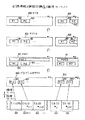
DVD1におけるオーディオデータ43としては、圧縮されたオーディオデータが記録される場合と、圧縮されていないオーディオデータが記録される場合があるが、このうち、圧縮されていないオーディオデータとしては、リニアPCM(Pulse Code Modulation )と呼ばれる方式で符号化されたオーディオデータ43が記録される。このリニアPCM方式のオーディオデータ43をDVD1に記録する場合の物理構造について、図3を用いて説明する。なお、本実施の形態におけるリニアPCM方式のオーディオデータ43は、24ビットの量子化ビット数により量子化されている。
【0067】
図3に示すように、リニアPCM方式のオーディオデータ43をDVD1に記録する際には、一のオーディオデータ43(以下、オーディオパックAPという。)は、オーディオパックAPの開始であることを示すスタートコード及び上記SCR等を含むパックヘッダ64を先頭に当該オーディオパックAPに含まれているデータがオーディオデータ43であることを示す識別情報を含むパケットヘッダ65と、当該オーディオパックAPに含まれているオーディオデータ43に関する情報である付加情報ADと、当該オーディオパックAPに含まれているオーディオデータ43を一定の再生時間(例えば、1/600秒)に対応するオーディオデータ43毎に区分した再生単位である複数のオーディオフレームAFにより構成されている。ここで、付加情報ADとしては、オーディオデータ43をリニアPCM方式で量子化する際の量子化ビット数(本実施の形態では24ビット)、その際のサンプリング周波数及び当該オーディオデータ43に含まれているチャネル数等の情報が記述される。ここで、オーディオデータ43に含まれているチャネル数とは、一のスピーカから出力されるべきオーディオデータ43により一のチャネルを構成するものであり、より具体的には、通常の左と右の二つのスピーカから再生されるべきオーディオデータ43のみを含む場合には、チャネル数は「2」であり、いわゆるサラウンド効果を有するオーディオデータ43が記録される場合には、スピーカの数分の、例えば4チャネル等とされる。
【0068】
そして、一のオーディオフレームAFは、上記一定の再生時間に対応するオーディオデータ43により以下に示すような形態で構成されている。
すなわち、一の量子化タイミングにおいて24ビットで量子化されている各チャネル毎のオーディオデータ43のうち、夫々の上位16ビットのオーディオデータ43である上位ビットデータ66を二つ含む一の上位データブロックUBと、夫々の下位8ビットのオーディオデータ43である下位ビットデータ67を二つ含む一の下位データブロックDBとにより一のサンプルブロックSPBを構成し、当該サンプルブロックSPBを上記一定の再生時間に対応する数だけ連結して一のオーディオフレームAFを構成する。
【0069】
更に、上位データブロックUBに含まれる二つの上位ビットデータ66は、リニアPCMの量子化における量子化タイミングのうち、偶数番目に対応する量子化タイミングにおいて量子化された16ビットの上位ビットデータ66A(図3中「S2n」で示す。)と、奇数番目に対応する量子化タイミングにおいて量子化された16ビットの上位ビットデータ66B(図3中「S2n+1」で示す。)とが含まれている。
【0070】
また、下位データブロックDBに含まれる二つの下位ビットデータ67は、リニアPCMの量子化における量子化タイミングのうち、上位ビットデータ66Aが生成された量子化タイミングである偶数番目に対応する量子化タイミングにおいて量子化された8ビットの下位ビットデータ67A(図3中「e2n」で示す。)と、上位ビットデータ66Bが生成された量子化タイミングである奇数番目に対応する量子化タイミングにおいて量子化された8ビットの下位ビットデータ67B(図3中「e2n+1」で示す。)とが含まれている。なお、図3において、夫々の上位ビットデータ66及び下位ビットデータ67内の括弧内の数は夫々のデータのビット数を示している。
【0071】
ここで、上記の上位ビットデータ66Aと下位ビットデータ67Aとが、偶数番目に対応する一の量子化タイミングにおいて量子化された24ビットのオーディオデータ43を構成し、更に、上記の上位ビットデータ66Bと下位ビットデータ67Bとが、奇数番目に対応する一の量子化タイミングにおいて量子化された24ビットのオーディオデータ43を構成する。従って、上位ビットデータ66Aと下位ビットデータ67Aの双方を再生時に組合わせて再生すれば、元の24ビットで量子化されたオーディオデータ43を再生することができ、同様に、上位ビットデータ66Bと下位ビットデータ67Bの双方を再生時に組合わせて再生すれば、元の24ビットで量子化されたオーディオデータ43を再生することとができるのである。
【0072】
更に、夫々の上位ビットデータ66及び下位ビットデータ67は、夫々に各チャネル毎のチャネル上位ビットデータ68とチャネル下位ビットデータ69とにより構成されている。なお、図3には、チャネルとして「A」乃至「D」の4つのチャネルを含んでいる状態を示しており、夫々のチャネル上位ビットデータ68又はチャネル下位ビットデータ69内の括弧内の数は夫々のデータのビット数を示している。
【0073】
なお、本発明に係る後述の再生装置において、オーディオデコーダが16ビットに対応する処理能力しか有していない場合には、各チャネル下位ビットデータ69は再生されない。この場合に、各チャネル下位ビットデータ69に含まれているオーディオデータ43は、それが再生されなくても聴感上問題がない程度の量子化ビット幅に対応するオーディオデータであるので、それが再生時に再生されなくても聴感上大きな問題はない(因みに、従来から知られているCDにおける量子化ビット数は16ビットであり、本実施の形態のDVD1においては、CDより更に高音質のオーディオデータ43を記録するため、量子化ビット数が最大で24ビットとされているのである。)。
【0074】
以上説明した図1に示す階層構造の記録フォーマットにおいて、夫々の区分は、DVD1内に記録させる記録情報の製作者(以下、単に製作者という。)がその意図に応じて自在に区分設定をして記録させるものである。これらの区分毎に後述の論理構造に基づいて再生することにより、変化に富んだ種々の再生が可能となるのである。
【0075】
次に、図1に示す物理的な区分により記録された情報を組合わせた論理的フォーマット(論理構造)について図4を用いて説明する。なお、図4に示す論理構造は、その構造で実際にDVD1上に情報が記録されているのではなく、図4に示す論理構造で図1に示す各データ(特にセル20)を組合わせて再生するための情報(アクセス情報又は時間情報等)がDVD1上の、特にコントロールデータ11の中に記録されているものである。
【0076】
説明の明確化のために、図4の下位の階層から説明していくと、上記図1において説明した物理構造のうち、複数のセル20を選択して組合わせることにより、一のプログラム60が製作者の意図に基づいて論理上構成される。このプログラム60は、後述の再生装置におけるシステムコントローラが区分を識別してコマンドによってアクセスできる最小の論理的単位でもある。なお、このプログラム60を一又は複数個纏めたものを視聴者が自由に選択して視聴することができる最小単位として製作者が定義することもでき、この単位をPTT(Part Of Title )という。
【0077】
また、一のプログラム60が複数のセル20を選択して論理的に構成されることから、複数のプログラム60で一のセル20を用いる、すなわち、一のセル20を異なった複数のプログラム60において再生させる、いわゆるセル20の使い回しを製作者が行うことも可能となっている。
【0078】
ここで、一のセル20の番号については、当該セル20を図1に示す物理フォーマットにおいて取り扱う際にはセルID番号として扱われ(図1中、セルID#と示す。)、図4に示す論理フォーマットにおいて取り扱う際には後述のPGCI中の記述順にセル番号として扱われる。
【0079】
次に、複数のプログラム60を組合わせて一のPGC(Program Chain )61が製作者の意図に基づいて論理上構成される。このPGC61の単位で、前述したPGCIが定義され、当該PGCIには、夫々のプログラム60を再生する際の各プログラム60毎のセル20の再生順序(この再生順序により、プログラム60毎に固有のプログラム番号が割当てられる。)、夫々のセル20のDVD1上の記録位置であるアドレス、一のプログラム60における再生すべき先頭セル20の番号、各プログラム60の再生方式[本実施の形態のDVD1に情報を記録する際には、再生時において、ランダム再生(乱数によるランダム再生であり、同じプログラム60が複数回再生されることがある。)、シャッフル再生(ランダム再生と同様の乱数によるランダム再生であるが、同じプログラム60は一度しか再生されず、同じプログラム60が複数回再生されることはない。)又はループ再生(一つのPGC61を何度も再生すること。)のうち、いずれか一つ、又はループ再生とランダム再生又はシャッフル再生の組合わせによる再生方法をPGC61毎に製作者が選択して再生させるようにすることができる。]及び各種コマンド(PGC61又はセル20毎に製作者が指定可能なコマンド)が含まれている。なお、PGCIのDVD1上の記録位置は、上述の通りコントロールデータ11(図1参照)内であるが、当該PGCIがビデオマネージャ2内のメニューに関するPGCIである場合には、当該PGCIの記録位置は、ビデオマネージャ2に含まれるコントロールデータ(図示を省略する。)内である。
【0080】
また、一のPGC61には、上記PGCIの他に、実体的な映像及び音声等のデータがプログラム60の組合わせとして(換言すれば、セル20の組合わせとして)含まれることとなる。
【0081】
更に、一のPGC61においては、上記のプログラム60における説明において示したセル20の使い回し(すなわち、異なるPGC61により、同一のセル20を用いること。)も可能である。また、使用するセル20については、DVD1に記憶されている順番にセル20を再生する方法(連続配置セルの再生)の他に、DVD1に記憶されている順序に関係なく再生する(例えば、後に記録されているセル20を先に再生する等)方法(非連続配置セルの再生)を製作者が選択することができる。
【0082】
次に、一又は複数のPGC61により、一のタイトル62が論理上構成される。このタイトル62は、例えば、映画一本に相当する単位であり、製作者がDVD1の視聴者に対して提供したい完結した情報である。
【0083】
そして、一又は複数のタイトル62により、一のVTS63が論理上構成される。このVTS63に含まれるタイトル62は、夫々に共通の属性を有するものであり、例えば、一本の同じ映画に対して違う言語の映画が夫々のタイトル62に相当することとなる。
【0084】
また、図4に示す一のVTS63に相当する情報は、図1に示す一のVTS3に含まれている情報に対応している。すなわち、DVD1には、図4に示すVTS63内に論理上含まれる全ての情報が一のVTS3として纏めて記録されていることとなる。
【0085】
以上説明した論理フォーマットに基づいて、物理構造において区分された情報を製作者が指定することにより、視聴者が見るべき映像(映画等)が形成されるのである。
【0086】
なお、図1に示す物理構造の説明においては、内容の理解の容易化のため、複数のセル20がID番号の順に記録されているとして説明したが、実施の形態のDVD1においては、実際には、一のセル20が図5に示す複数のインターリーブドユニットIUに分割されて記録される場合がある。
【0087】
すなわち、例えば図5に示すように、製作者が一のPGC61AをID番号1、2及び4を有するセル20により構成し、他のPGC61BをID番号1、3及び4を有するセル20により構成する場合を考えると、当該PGC61Aに基づいてDVD1から情報を再生する際には、ID番号1、2及び4を有するセル20のみを再生し、PGC61Bに基づいてDVD1から情報を再生する際には、ID番号1、3及び4を有するセル20のみを再生することとなる。この場合に、セル20がID番号毎に纏められて相互に分離して記録されていると、例えば、PGC61Aの場合には、ID番号2のセル20のDVD1上の記録位置からID番号4のセル20のDVD1上の記録位置まで、再生のためのピックアップをジャンプする時間が必要となり、後述の再生装置におけるトラックバッファの容量によっては、ID番号2のセル20とID番号4のセル20を連続的に再生すること(以下、これをシームレス再生という。)ができなくなる。
【0088】
そこで、図5に示す場合には、ID番号2のセル20とID番号3のセル20を、後述の再生装置におけるトラックバッファにおける入出力処理の速度に対応して、一時的に入力信号の入力が停止しても、出力信号の連続性が損なわれない長さのインターリーブドユニットIU(すなわち、一のインターリーブドユニットIUの間だけ再生装置におけるピックアップがジャンプすることによりトラックバッファへの入力信号が途絶えても、当該トラックバッファからの出力信号を連続的に出力可能な長さのインターリーブドユニットIU)に夫々分解して記録し、例えば、PGC61Aに基づいて再生する場合には、ID番号2に対応するセル20を構成するインターリーブドユニットIUのみを連続して検出し、再生することが行われる。同様に、PGC61Bに基づいて再生する場合には、ID番号3に対応するセル20を構成するインターリーブドユニットIUのみを連続して検出し、再生するのである。なお、インターリーブドユニットIUの長さは、上述のように、トラックバッファの容量を勘案して決定される他に、トラックジャンプを行うためのスライダモータ等の駆動機構の性能をも加味して決定される場合がある。
【0089】
このように、製作者の意図によって、一のセル20を複数のインターリーブドユニットIUに分割して記録しておくことにより、飛び飛びのID番号のセル20を含むPGC61を再生する際にも、トラックバッファから出力される信号は途切れることはなく、従って、視聴者は中断することのない再生映像を視聴することができるのである。
【0090】
なお、上記インターリーブドユニットIUを形成する際には、一のVOB10内で完結するように形成され、一のインターリーブドユニットIUが隣り合う複数のVOB10に跨がることはない。また、インターリーブドユニットIUとVOBユニット30との関係については、一のインターリーブドユニットIU内に一又は複数のVOBユニット30が含まれ、一のインターリーブドユニットIU内においては一のVOBユニット30が完結するように構成されており、一のVOBユニット30が分割されて複数のインターリーブドユニットIUに跨がることはない。
【0091】
以上説明したような種々の階層の情報を記録する必要があるため、上述の記録フォーマットを有する記録情報は、上記DVD1のように、一本の映画を記録する他に、当該映画に対応する音声又は字幕等について、複数種類の言語の音声又は字幕をも同一の光ディスクに記録することが可能な大きな記憶容量を有する情報記録媒体に特に適している。
(II)記録装置の実施の形態
次に、上述の制御情報、映像情報及び音声情報をDVD1に記録するための本願に対応する記録装置の実施の形態について、図6及び図7を用いて説明する。
【0092】
図6に示すように、実施の形態に係る記録装置S1 は、VTR(Video Tape Recorder )70と、メモリ71と、信号処理部72と、ハードディスク装置73及び74と、コントローラ75と、多重器76と、変調器77と、記録手段としてのマスタリング装置78とにより構成されている。
【0093】
また、図7に示すように、信号処理部72は、処理部72Aと、量子化手段としての量子化部72Bと、分割部72C及び分割手段としての分割部72Dと、多重記録情報生成手段としての多重部72Eと、多重部72Fと、制御情報生成部72Gとにより構成されている。
【0094】
次に、動作を説明する。
VTR70には、DVD1に記録すべき音声情報や映像情報等の素材である記録情報Rが夫々の情報毎に一時的に記録されている。そして、VTR70に一時的に記録された記録情報Rは、信号処理部72からの要求により音声情報又は映像情報毎に当該信号処理部72に出力される。
【0095】
信号処理部72における処理部72Aは、入力された映像情報をA/D変換した後、MPEG2方式を用いて圧縮処理し、GOP52により構成される処理映像信号Srvを出力する。そして、分割部72Cは、VTR70から出力される上記記録情報Rに対応したタイムコードTt に基づいて、処理映像信号Srvをビデオパック(図1参照)に分割し、分割処理映像信号Srvp を出力する。
【0096】
一方、信号処理部72における量子化部72Bは、入力された音声情報を24ビットの量子化ビット数によるリニアPCM方式で量子化して量子化音信号Sraを出力する。
【0097】
そして、分割部72Dは、量子化音信号Sraに含まれている各量子化タイミングにおいて量子化された24ビットのオーディオデータ43を、当該量子化タイミング毎に上位16ビットの上位ビットデータ66と下位8ビットの下位ビットデータ67とに分割し、分割量子化音信号Srap を出力する。このとき、分割量子化音信号Srap 中の上位ビットデータ66には各チャネル毎の16ビットのチャネル上位ビットデータ68が含まれており、更に、分割量子化音信号Srap 中の下位ビットデータ67には各チャネル毎の8ビットのチャネル下位ビットデータ69が含まれている(図3参照)。
【0098】
次に、多重部72Eは、出力された分割量子化音信号Srap に含まれる各量子化タイミングに対応する上位ビットデータ66及び下位ビットデータ67から、偶数番目の量子化タイミングに対応する上位ビットデータ66Aと奇数番目の量子化タイミングに対応する上位ビットデータ66Bとを抽出し、これらにより上位ビットデータブロックUBを構成するように当該上位ビットデータ66Aと上位ビットデータ66Bとを多重すると共に、上位ビットデータ66Aが生成された量子化タイミングである偶数番目の量子化タイミングに対応する下位ビットデータ67Aと上位ビットデータ66Bが生成された量子化タイミングである奇数番目の量子化タイミングに対応する下位ビットデータ67Bとを抽出し、これらにより下位ビットデータブロックDBを構成するように当該下位ビットデータ67Aと下位ビットデータ67Bとを多重する。更に、多重部72Eは、上記構成された上位ビットデータブロックUBを一時的に記憶し、必要に応じて読み出すことにより、上位ビットデータブロックUBと下位ビットデータブロックDBとが隣接するように当該上位ビットデータブロックUBと下位ビットデータブロックDBとを多重してサンプルブロックSPBを構成し、所定の再生時間(1/600秒)に対応する所定数のサンプルブロックSPBを一纏まりとしてオーディオフレームAFを構成し、多重量子化音信号Srappとして出力する。
【0099】
なお、オーディオフレームAFが構成された後に、後述の制御信号Si に含まれている上記付加情報ADがパックヘッダ64及びパケットヘッダ65と共に上記所定数のサンプルブロックSPB毎に多重されることにより、図3に示す一のオーディオパックAPが構成されており、上記多重量子化音信号Srappは複数のオーディオパックAPを含んでいることとなる。
【0100】
そして、多重部72Fにおいて、タイムコードTt に基づき、分割部72Cから出力されたビデオパックを含む分割処理映像信号Srvp と多重部72Eから出力されたオーディオパックAPを含む多重量子化音信号Srappとが各パック毎に多重され、圧縮多重信号Sr として出力される。その後、出力された圧縮多重信号Sr は、ハードディスク装置73に一時的に記憶される。この圧縮多重信号Sr においては、図1又は図3最上段に示すように、ビデオパックとオーディオパックAPとがパック毎に多重された状態となっている。
【0101】
これらと並行して、メモリ71は、上記記録情報Rの再生を制御するための制御情報(図1における、ビデオマネージャ2、コントロールデータ11並びにPCIデータ50及びDSIデータ51を含むナビパック41等)が記載されたキューシートSTに基づき予め入力された当該制御情報を一時的に記憶し、信号処理部72に含まれる制御情報生成部72Gからの要求に基づいて制御情報信号Si として出力する。この制御情報信号Si に含まれる付加情報ADは、上述の如く、多重部72Eに出力される。
【0102】
そして、制御情報生成部72Gは、上記タイムコードTt 及びメモリ71から出力される制御情報信号Si に基づき、タイムコードTt を参照して制御情報からPCIデータ50及びDSIデータ51を分離し、対応するPCI情報信号Spci 及びDSI情報信号Sdsi として出力し、当該PCI情報信号Spci 及びDSI情報信号Sdsi がハードディスク装置74に一時的に記憶される。このとき、PCIデータ50及びDSIデータ51以外の他の制御情報については、図6及び図7においては図示を省略しているが、PCIデータ50及びDSIデータ51と同様に制御情報生成部72Fにおいて夫々に分離され、ハードディスク装置74に記憶される。
【0103】
以上の処理が記録情報R全体について実行される。
記録情報Rの全てについて上記の処理が終了すると、コントローラ75は、ハードディスク装置73から圧縮多重信号Sr を読み出すとともにハードディスク装置74からPCI情報信号Spci 及びDSI情報信号Sdsi 並びにその他の制御情報を読み出し、これらに基づいてPCIデータ50及びDSIデータ51並びにその他の制御信号を夫々独立に含む付加情報を生成し、ハードディスク装置74に一時的に再記録する。これは、各制御情報の中には、圧縮多重信号Sr の生成結果によって内容が定まるものがあるからである。
【0104】
一方、コントローラ75は、上記信号処理部72、ハードディスク装置73及び74の夫々の動作の時間管理を行い、PCI情報信号Spci 及びDSI情報信号Sdsi を含む付加情報に対応する付加情報信号Sa をハードディスク装置74から読み出して出力すると共に、圧縮多重信号Sr と付加情報信号Sa を時間軸多重するための情報選択信号Sccを生成して出力する。
【0105】
その後、圧縮多重信号Sr と付加情報信号Sa は、コントローラ75からの情報選択信号Scc に基づき、ハードディスク装置73又は74から読み出され、多重器76により時間軸多重されて情報付加圧縮多重信号Sapとして出力される。この情報付加圧縮多重信号Sapの段階では、記録すべき情報は、コントローラ75の情報選択信号Sccを用いた切り換え動作によって制御情報と映像情報及び音声情報とが合成され、図1又は図3最上段に示す物理構造(物理フォーマット)となっている。そして、PCIデータ50及びDSIデータ51については、他の制御情報と独立してナビパック41に含まれていることとなる。
【0106】
なお、記録すべき情報の中に副映像情報が含まれている場合には、図示しない他のハードディスク装置から読み出されて信号処理部72に入力され、映像情報及び音声情報と同様に信号処理され、情報付加圧縮多重信号Sapに含まれる。
【0107】
その後、変調器77は、出力された情報付加圧縮多重信号Sapに対してリードソロモン符号等のエラー訂正コード(ECC)の付加及び8−16変調等の変調を施してディスク記録信号Sm を生成し、マスタリング装置78に出力する。
【0108】
最後に、マスタリング装置78は、当該ディスク記録信号Sm を光ディスクを製造する際のマスタ(抜き型)となるスタンパディスクに対して記録する。そして、このスタンパディスクを用いて図示しないレプリケーション装置により、一般に市販されるレプリカディスクとしての光ディスクが製造される。
【0109】
以上説明したように、実施の形態の記録装置S1 によれば、24ビットで量子化されたオーディオデータ43が、上位16ビットの上位ビットデータ66と下位8ビットの下位ビットデータ67とに分割され、連続する量子化タイミングに対応する二つずつの上位ビットデータ66及び下位ビットデータ67により夫々上位ビットデータブロックUB及び下位ビットデータブロックDBが構成されてDVD1に記録されるので、オーディオデータ43の再生時において、オーディオデコーダが16ビットの処理能力しか有しないときは、上記上位ビットデータブロックUBのみを抽出してそれに含まれる上位ビットデータ66をD/A変換して再生することができる。
【0110】
また、オーディオデコーダが24ビットのD/A変換処理が可能であるときは、上位ビットデータ66及び下位ビットデータ67を抽出して対応する上位ビットデータ66と下位ビットデータ67を対としてD/A変換することができる。
【0111】
更に、上位ビットデータ66及び下位ビットデータ67が共に8の倍数のビット数を有しているので、8ビットのディジタル信号処理において処理を簡略化できる。
【0112】
更にまた、偶数番目の量子化タイミングに対応する上位ビットデータ66Aと奇数番目の量子化タイミングに対応する上位ビットデータ66Bとにより上位ビットデータブロックUBが構成され、偶数番目の量子化タイミングに対応する下位ビットデータ67Aと奇数番目の量子化タイミングに対応する下位ビットデータ67Bとにより下位ビットデータブロックDBが構成されて記録されるので、再生装置のオーディオデコーダにおいて24ビットのD/A変換処理が可能であるときは、D/A変換処理において上位ビットデータ66と下位ビットデータ67を合成するとき必要なメモリの容量を低減できる。
【0113】
また、オーディオデータ43に含まれるチャネル数によらず、上位ビットデータブロックUBと下位ビットデータブロックDBが共に16ビットの整数倍の大きさとなるので、ディジタル信号処理がいっそう容易なものとなる。
(III)再生装置の実施の形態
次に、上記の記録装置S1によりDVD1に記録された記録情報を再生するための本願に対応する再生装置の実施の形態を、図8乃至図10を用いて説明する。
【0114】
図8に示すように、実施の形態に係る再生装置S2 は、検出復調手段としてのピックアップ80と、検出復調手段としての復調訂正部81と、ストリームスイッチ82及び84と、トラックバッファ83と、システムバッファ85と、デマルチプレクサ86と、VBV(Video Buffer Verifier )バッファ87と、ビデオデコーダ88と、サブピクチャバッファ89と、サブピクチャデコーダ90と、混合器91と、オーディオバッファ92と、オーディオデコーダ93と、PCIバッファ94と、PCIデコーダ95と、ハイライトバッファ96と、ハイライトデコーダ97と、入力部98と、ディスプレイ99と、システムコントローラ100と、ドライブコントローラ101と、スピンドルモータ102と、スライダモータ103とにより構成されている。なお、図8に示す構成は、再生装置S2 の構成のうち、映像及び音声の再生に関する部分のみを記載したものであり、ピックアップ80及びスピンドルモータ102並びにスライダモータ103等をサーボ制御するためのサーボ回路等は従来技術と同様であるので、記載及び細部説明を省略する。
【0115】
次に、全体動作を説明する。
ピックアップ80は、図示しないレーザダイオード、偏向ビームスプリッタ、対物レンズ、光検出器等を含み、DVD1に対して再生光としての光ビームBを照射すると共に、当該光ビームBのDVD1からの反射光を受光し、DVD1上に形成されている情報ピット(DVD1においては、情報ピットを形成することにより上記記録情報が記録されている。)に対応する検出信号Sp を出力する。このとき、光ビームBがDVD1上の情報トラックに対して正確に照射されると共に、DVD1上の情報記録面で正確に焦点を結ぶように、図示しない対物レンズに対して従来技術と同様の方法によりトラッキングサーボ制御及びフォーカスサーボ制御が施されている。
【0116】
ピックアップ80から出力された検出信号Sp は、復調訂正部81に入力され、復調処理及び誤り訂正処理が行われて復調信号Sdmが生成され、ストリームスイッチ82及びシステムバッファ85に出力される。
復調信号Sdmが入力されたストリームスイッチ82は、ドライブコントローラ101からのスイッチ信号Ssw1 によりその開閉が制御され、閉のときには、入力された復調信号Sdmをそのままスルーしてトラックバッファ83に出力する。一方、ストリームスイッチ82が開のときには、復調信号Sdmは出力されず、不要な情報(信号)がトラックバッファ83に入力されることがない。
【0117】
復調信号Sdmが入力されるトラックバッファ83は、FIFO(First In First Out)メモリ等により構成され、入力された復調信号Sdmを一時的に記憶すると共に、ストリームスイッチ84が閉とされているときには、記憶した復調信号Sdmを連続的に出力する。トラックバッファ83は、MPEG2方式における各GOP毎のデータ量の差を補償すると共に、インターリーブドユニットIUに分割されたデータの読み取りの際等に、上記のシームレス再生におけるトラックジャンプに起因して不連続に入力される復調信号Sdmを連続的に出力し、当該不連続による再生の中断を解消するためのものである。
【0118】
連続的に復調信号Sdmが入力されるストリームスイッチ84は、デマルチプレクサ86における分離処理において、後段の各種バッファがオーバーフローしたり、逆に空になってデコード処理が中断することがないように、システムコントローラ100からのスイッチ信号Ssw2 により開閉が制御される。
【0119】
一方、トラックバッファ83と並行して復調信号Sdmが入力されるシステムバッファ85は、DVD1をローディングしたときに最初に検出され、DVD1に記録されている情報全体に関する管理情報(ビデオマネージャ2等)又はVTS3毎のコントロールデータ11を蓄積して制御情報Sc としてシステムコントローラ100に出力すると共に、再生中にナビパック41毎のDSIデータ51を一時的に蓄積し、システムコントローラ100に制御情報Sc として出力する。
【0120】
ストリームスイッチ84を介して復調信号Sdmが連続的に入力されたデマルチプレクサ86においては、当該復調信号Sdmから各パック毎にビデオデータ42、オーディオデータ43、サブピクチャデータ44及びナビパック41毎のPCIデータ50を抽出し、ビデオ信号Sv 、副映像信号Ssp、オーディオ信号Sad並びにPCI信号Spcとして、夫々VBVバッファ87、サブピクチャバッファ89、オーディオバッファ92及びPCIバッファ94に出力する。なお、復調信号Sdmには、オーディオデータ43又はサブピクチャデータ44として複数の言語が別々のストリームとして含まれている場合があるが、その場合には、システムコントローラ100からのストリーム選択信号Slcにより所望の言語が夫々選択されてオーディオバッファ92又はサブピクチャバッファ89に出力される。
【0121】
このとき、デマルチプレクサ86は、各パック(オーディオパックAPを含む。)及びパケットからパックヘッダ及びパケットヘッダを抽出し、夫々に含まれる情報をヘッダ信号Shdとしてシステムコントローラ100に出力する。
【0122】
また、オーディオ信号Sadには、図3に示す形態のオーディオパックAPに分割されたオーディオデータ43が含まれており、各オーディオパックAPには、図3に示す付加情報AD及び複数のサンプルブロックSPBが含まれている。
【0123】
ビデオ信号Sv が入力されるVBVバッファ87は、FIFOメモリ等により構成され、ビデオ信号Sv を一時的に蓄積し、ビデオデコーダ88に出力する。VBVバッファ87は、MPEG2方式により圧縮されているビデオ信号Sv における各ピクチャ(図2参照)毎のデータ量のばらつきを補償するためのものである。そして、データ量のばらつきが補償されたビデオ信号Sv がビデオデコーダ88に入力され、MPEG2方式により復調が行われて復調ビデオ信号Svdとして混合器91に出力される。
【0124】
一方、副映像信号Sspが入力されるサブピクチャバッファ89は、入力された副映像信号Sspを一時的に蓄積し、サブピクチャデコーダ90に出力する。サブピクチャバッファ89は、副映像信号Sspに含まれるサブピクチャデータ44を、当該サブピクチャデータ44に対応するビデオデータ42と同期して出力するためのものである。そして、ビデオデータ42との同期が取られた副映像信号Sspがサブピクチャデコーダ90に入力され、復調が行われて復調副映像信号Sspd として混合器91に出力される。
【0125】
なお、副映像信号Sspが、上記メニュー画面を構成して表示するために必要な、枠、選択ボタン等を構成するための映像情報を含んでいる場合には、システムコントローラ100からのハイライト制御信号Schに基づき、表示すべき選択ボタン等の表示状態の変更を行って出力する。
【0126】
ビデオデコーダ88から出力された復調ビデオ信号Svd及びサブピクチャデコーダ90から出力された復調副映像信号Sspd (対応する復調ビデオ信号Svdとの同期が取れている。)は、混合器91により混合され、最終的な表示すべき映像信号Svpとして図示しないCRT(Cathod Ray Tube )等の表示部に出力される。
【0127】
次に、オーディオ信号Sadが入力されるオーディオバッファ92は、FIFOメモリ等により構成され、入力されたオーディオ信号Sadを一時的に蓄積し、オーディオデコーダ93に出力する。オーディオバッファ92は、オーディオ信号Sadを対応する映像情報を含むビデオ信号Sv 又は副映像信号Sspに同期して出力させるためのものであり、対応する映像情報の出力状況に応じてオーディオ信号Sadを遅延させる。そして、対応する映像情報と同期するように時間調整されたオーディオ信号Sadは、オーディオデコーダ93に出力され、D/A変換等の所定のデコードが施されて復調オーディオ信号Sadd として図示しないスピーカ等に出力される。
【0128】
また、所望の情報へのアクセス直後の再生等において一時的に音声を中断する(ポーズする)必要があることが検出された場合には、システムコントローラ100からポーズ信号Scaがオーディオデコーダ93に出力され、当該オーディオデコーダ93において一時的に復調オーディオ信号Sadd の出力を停止する。このオーディオデコーダ93における処理については、後ほど、当該オーディオデコーダ93が24ビットのD/A変換能力を有する場合と16ビットのD/A変換能力しか有しない場合とに分けて詳説する。
【0129】
更に、PCI信号Spcが入力されるPCIバッファ94は、FIFOメモリ等により構成され、入力されたPCI信号Spcを一時的に蓄積し、PCIデコーダ95に出力する。PCIバッファ94は、PCI信号Spcに含まれるPCIデータ50と当該PCIデータ50が対応するビデオデータ42、オーディオデータ43又はサブピクチャデータ44等とを同期させ、当該ビデオデータ42、オーディオデータ43又はサブピクチャデータ44等にPCIデータ50を適用させるためのものである。そして、PCIバッファ94により対応するビデオデータ42、オーディオデータ43又はサブピクチャデータ44等と同期したPCI信号Spcは、PCIデコーダ95によりPCIデータ50に含まれるハイライト情報が分離され、ハイライト信号Shiとしてハイライトバッファ96に出力されると共に、PCIデータ50のハイライト情報以外の部分がPCI情報信号Spci としてシステムコントローラ100に出力される。
【0130】
ハイライト信号Shiが入力されるハイライトバッファ96は、FIFOメモリ等により構成され、入力されたハイライト信号Shiを一時的に蓄積し、ハイライトデコーダ97に出力する。ハイライトバッファ96は、当該ハイライト情報のための映像情報が含まれている副映像信号Sspに対応して、ハイライト情報に対応する選択項目(選択ボタン)の表示状態の変更が正確に行われるための時間軸補償を行うためのバッファである。そして、時間軸補償が行われたハイライト信号Shiは、ハイライトデコーダ97においてデコードされ、当該ハイライト信号Shiに含まれる情報が復調ハイライト信号Shid としてシステムコントローラ100に出力される。この復調ハイライト信号Shid の中に上記システムコントローラ100内のレジスタを設定するための情報が含まれている。
【0131】
ここで、システムコントローラ100は、当該復調ハイライト信号Shid に基づき、ハイライト情報による表示状態の変更を行うべく、上記のハイライト制御信号Schを出力することとなる。このとき、システムコントローラ100は、復調ハイライト信号Shid に含まれるハイライト情報の有効期間を示す有効期間情報に基づいて当該ハイライト情報に基づくメニュー画面等を用いた選択動作を有効とすべく、入力部98からの入力信号Sinによる選択動作を受け付けると共に、上記ハイライト制御信号Schを出力することとなる。
【0132】
更に、システムコントローラ100は、システムバッファ85から入力される制御情報Sc 、デマルチプレクサ86から入力されるヘッダ信号Shd、システムPCIデコーダ95から入力されるPCI情報信号Spci 及びリモコン等の入力部98から入力される入力信号Sinに基づき、それらの信号に対応した正しい再生を行うために上記のスイッチ信号Ssw2 、ストリーム選択信号Slc、ポーズ信号Sca、ハイライト制御信号Schを出力すると共に、再生装置S2 の動作状況等を表示するために表示信号Sdpを液晶表示装置等のディスプレイ99に出力する。
【0133】
更にまた、システムコントローラ100は、上記DSI情報信号Sdsi 等により、シームレス再生のためにサーチ等のトラックジャンプの処理が必要であることを検出したときには、ドライブコントローラ101に対して、当該トラックジャンプの処理に対応するシームレス制御信号Scsl を出力する。
【0134】
そして、シームレス制御信号Scsl が入力されたドライブコントローラ101は、スピンドルモータ102又はスライダモータ103に対して駆動信号Sd を出力する。この駆動信号Sd により、スピンドルモータ102又はスライダモータ103は、光ビームBが再生すべきDVD1上の記録位置に照射されるようにピックアップ2を移動させる(図8破線矢印参照)と共に、DVD1の回転数をCLV(Constant Linear Velocity:線速度一定)制御する。これと並行して、ドライブコントローラ101は、ピックアップ2が移動中であり復調訂正部81から復調信号Sdmが出力されないときには、シームレス制御信号Scsl に基づきスイッチ信号Ssw1 を出力し、ストリームスイッチ82を開とすると共に、復調信号Sdmが出力され始めると、ストリームスイッチ82を閉成して復調信号Sdmをトラックバッファ83に出力する。
【0135】
次に、上記のオーディオデコーダ93における処理について、当該オーディオデコーダ93が24ビットのD/A変換能力を有する場合と16ビットのD/A変換能力しか有しない場合とに分けて詳説する。
(A)オーディオデコーダの第1実施形態
始めに、16ビットのD/A変換能力しか有しないオーディオデコーダ93(以下、オーディオデコーダ93-1という。)の構成及び動作について、図9を用いて説明する。
【0136】
図9(a)に示すように、オーディオデコーダ93-1の場合、当該オーディオデコーダ93-1は、入力されたオーディオ信号Sadに含まれるオーディオパックAPから上位ビットデータブロックUBのみを抽出し、抽出信号Sapとして出力する記録情報ブロック抽出手段としての抽出部93Aと、抽出信号Sapに含まれる上位ビットデータ66を16ビットでD/A変換して復調オーディオ信号Sadd を出力する再生処理手段としてのデコード部93Bとにより構成されている。
【0137】
次に、図9(b)に示すフローチャートを用いて動作を説明する。
図9(b)に示すように、オーディオデコーダ93-1においては、オーディオバッファ92からオーディオ信号Sadが入力されると、始めに、抽出部93Aにおいて、当該オーディオ信号Sadに含まれるオーディオパックAPから上位ビットデータブロックUBのみを抽出して抽出信号Sapを出力する(ステップS1)。この上位ビットデータブロックUBのみの抽出は、オーディオパックAPに含まれている付加情報ADにおける量子化ビット数及び当該オーディオパックAPに含まれているチャネル数の情報に基づき、オーディオパックAPの先頭からの上位ビットデータブロックUBの位置を算出し、これにより上位ビットデータブロックUBのみを抽出すると共に、下位ビットデータブロックDBを破棄する(読み跳ばす。)。
【0138】
オーディオパックAPから上位ビットデータブロックUBのみが抽出されると(ステップS1)、次に、デコード部93Bにおいて、抽出信号Sapに含まれる上位ビットデータ66を抽出すると共に当該上位ビットデータ66に含まれるチャネル上位ビットデータ68を各チャネル毎に抽出し(ステップS2)、その後、各チャネル毎にチャネル上位ビットデータ68を16ビットでD/A変換し、復調オーディオ信号Sadd を出力する(ステップS3)。
【0139】
そして、全てのデータについて処理が終了したか否かが判断され(ステップS4)、終了している場合には(ステップS4;YES)処理を終了し、終了していない場合には(ステップS4;NO)、次のデータについて処理を行うべくステップS1に戻る。
【0140】
以上の動作により、16ビットの上位ビットデータブロックUBのみを抽出してオーディオデータ43のD/A変換が行われ、各チャネル毎に復調オーディオ信号Sadd が出力されて対応する図示しないスピーカ等から音として出力される。
(B)オーディオデコーダの第2実施形態
次に、24ビットのD/A変換能力を有するオーディオデコーダ93(以下、オーディオデコーダ93-2という。)の構成及び動作について、図10を用いて説明する。
【0141】
図10(a)に示すように、オーディオデコーダ93-2の場合、当該オーディオデコーダ93-2は、入力されたオーディオ信号Sadに含まれるオーディオパックAPから上位ビットデータブロックUB及び下位ビットデータブロックDBを抽出し、第1抽出信号Sap1 として出力する記録情報ブロック抽出手段としての第1抽出部93Cと、第1抽出信号Sap1 に含まれる上位ビットデータブロックUB及び下位ビットデータブロックDBから夫々上位ビットデータ66及び下位ビットデータ67を各チャネル毎に抽出して第2抽出信号Sap2 として出力する量子化記録情報抽出手段としての第2抽出部93Dと、第2抽出信号Sap2 に含まれる上位ビットデータ66及び下位ビットデータ67のうち、偶数番目の量子化タイミングに対応する上位ビットデータ66Aと偶数番目の量子化タイミングに対応する下位ビットデータ67Aとを各チャネル毎に合成すると共に、奇数番目の量子化タイミングに対応する上位ビットデータ66Bと奇数番目の量子化タイミングに対応する下位ビットデータ67Bとを各チャネル毎に合成し、夫々24ビットのオーディオデータ43を再構成し、各チャネル毎にD/A変換して復調オーディオ信号Sadd を出力する再生処理手段としてのデコード部93Eとにより構成されている。
【0142】
次に、図10(b)に示すフローチャートを用いて動作を説明する。
図10(b)に示すように、オーディオデコーダ93-2においては、オーディオバッファ92からオーディオ信号Sadが入力されると、始めに、第1抽出部93Cにおいて、当該オーディオ信号Sadに含まれるオーディオパックAPから上位ビットデータブロックUB及び下位ビットデータブロックDBを抽出して第1抽出信号Sap1 として出力する(ステップS10)。この上位ビットデータブロックUB及び下位ビットデータブロックDBの抽出は、オーディオパックAPに含まれている付加情報ADにおける量子化ビット数及び当該オーディオパックAPに含まれているチャネル数の情報に基づき、オーディオパックAPの先頭からの上位ビットデータブロックUB及び下位ビットデータブロックDBの位置を算出し、これにより上位ビットデータブロックUB及び下位ビットデータブロックDBを個別に抽出するものである。
【0143】
オーディオパックAPから上位ビットデータブロックUB及び下位ビットデータブロックDBが抽出されると(ステップS10)、次に、第2抽出部93Dにおいて、上位ビットデータブロックUB及び下位ビットデータブロックDBから夫々上位ビットデータ66及び下位ビットデータ67を各チャネル毎に抽出して第2抽出信号Sap2 として出力する(ステップS11)。この各チャネル毎の抽出は、上位ビットデータ66及び下位ビットデータ67において、チャネル上位ビットデータ68及びチャネル下位ビットデータ69が夫々16ビット及び8ビットずつの区切りといして含まれているのが予め判っているので、抽出した上位ビットデータ66の先頭から16ビットずつ区切って抽出することによりチャネル上位ビットデータ68を得ると共に、抽出した下位ビットデータ67の先頭から8ビットずつ区切って抽出することによりチャネル下位ビットデータ69を得るものである。
【0144】
そして、各チャネル毎に上位ビットデータ66及び下位ビットデータ67が抽出されると(ステップS11)、次に、デコーダ部93Eにおいて、抽出した上位ビットデータ66及び下位ビットデータ67を一時的に記憶しておくことにより、偶数番目の量子化タイミングに対応する上位ビットデータ66Aと偶数番目の量子化タイミングに対応する下位ビットデータ67Aとを各チャネル毎に合成すると共に、奇数番目の量子化タイミングに対応する上位ビットデータ66Bと奇数番目の量子化タイミングに対応する下位ビットデータ67Bとを各チャネル毎に合成し、夫々24ビットのオーディオデータ43を再構成する(ステップS12)。このオーディオデータ43の再構成は、各オーディオフレームAF毎に、行われる。そして、再構成された24ビットのオーディオデータ43を、各チャネル毎にD/A変換して復調オーディオ信号Sadd を出力する(ステップS13)。
【0145】
そして、全てのデータについて処理が終了したか否かが判断され(ステップS14)、終了している場合には(ステップS14;YES)処理を終了し、終了していない場合には(ステップS14;NO)、次のデータについて処理を行うべくステップS10に戻る。
【0146】
以上の動作により、上位ビットデータブロックUB及び下位ビットデータブロックDBを抽出して24ビットのオーディオデータ43のD/A変換が行われ、各チャネル毎に復調オーディオ信号Sadd が出力されて対応する図示しないスピーカ等から音として出力される。
【0147】
以上説明したように、実施形態の再生装置S2 によれば、DVD1において、24ビットで量子化されたオーディオデータ43が、上位16ビットの上位ビットデータ66と下位8ビットの下位ビットデータ67とに分割され、連続する量子化タイミングに対応する二つずつの上位ビットデータ66及び下位ビットデータ67により夫々上位ビットデータブロックUB及び下位ビットデータブロックDBが構成されて記録されているので、オーディオデコーダが16ビットの処理能力しか有しないときは、上記上位ビットデータブロックUBのみを抽出してそれに含まれる上位ビットデータ66をD/A変換して再生することができる。
【0148】
また、オーディオデコーダが24ビットのD/A変換処理が可能であるときは、上位ビットデータ66及び下位ビットデータ67を抽出して対応する上位ビットデータ66と下位ビットデータ67を対としてD/A変換することができる。
【0149】
更に、上位ビットデータ66及び下位ビットデータ67が共に8の倍数のビット数を有しているので、8ビットのディジタル信号処理において処理を簡略化できる。
【0150】
更にまた、偶数番目の量子化タイミングに対応する上位ビットデータ66Aと奇数番目の量子化タイミングに対応する上位ビットデータ66Bとにより上位ビットデータブロックUBが構成され、偶数番目の量子化タイミングに対応する下位ビットデータ67Aと奇数番目の量子化タイミングに対応する下位ビットデータ67Bとにより下位ビットデータブロックDBが構成されて記録されるので、オーディオデコーダが24ビットのD/A変換処理が可能であるときは、D/A変換処理において上位ビットデータ66と下位ビットデータ67を合成するとき必要な当該オーディオデコーダ内のメモリの容量を低減できる。
【0151】
また、オーディオデータ43に含まれるチャネル数によらず、上位ビットデータブロックUBと下位ビットデータブロックDBが共に16ビットの整数倍の大きさとなるので、ディジタル信号処理がいっそう容易なものとなる。
【0152】
なお、上記の各実施形態においては、オーディオデータ43が24ビットの量子化ビット数を有するリニアPCM方式でDVD1に記録されており、その内、上位16ビットを上位ビットデータ66とし、下位8ビットを下位ビットデータとした場合について説明したが、本発明これに限らず、8×n(nは自然数)ビットで量子化されたオーディオデータを再生時の聴感上影響の大きい上位8×m(m<n、且つ、mは自然数)ビットを上位ビットデータとし、再生時の聴感上影響の小さい下位8×r(r=n−m、且つ、rは自然数)ビットを下位ビットデータとした場合にも適用できるものである。
【0153】
更に、情報記録媒体の形態も上記DVD1に限られるものではない。
【0154】
【発明の効果】
以上説明したように、請求項1に記載の発明によれば、複数のチャンネルからなる記録情報が、当該各チャンネル毎に、上位の8×mビットの上位ビット量子化記録情報とそれ以外の下位ビット量子化記録情報とに分割され、複数の上位ビット量子化記録情報及び下位ビット量子化記録情報により夫々上位ビット量子化記録情報ブロック及び下位ビット量子化記録情報ブロックが各チャンネル分構成され、更に上位ビット量子化記録情報ブロックと下位ビット量子化記録情報ブロックとが隣接して記録情報ブロックが構成され、連続する複数の記録情報ブロックにより構成される記録情報フレームが複数構成されて情報記録媒体に記録されるので、記録情報の再生時において、上記上位ビット量子化記録情報ブロックのみを抽出してそれに含まれる上位ビット量子化記録情報を再生処理することができる。
【0155】
従って、上位ビット量子化記録情報のビット数に相当する再生処理のみが可能な再生処理手段を有する再生装置において、容易に記録情報の再生が可能となる。
【0156】
また、上位ビット量子化記録情報ブロック及び下位ビット量子化記録情報ブロックの双方を合わせたビット数に相当する再生処理が可能な再生処理手段を有する再生装置においても、上位ビット量子化記録情報及び下位ビット量子化記録情報を抽出して対応する上位ビット量子化記録情報と下位ビット量子化記録情報を対として再生処理することができ、容易に記録情報の再生が可能となる。
【0157】
請求項6に記載の発明によれば、複数のチャンネルからなる記録情報が、当該各チャンネル毎に、上位の8×mビットの上位ビット量子化記録情報とそれ以外の下位ビット量子化記録情報とに分割され、複数の上位ビット量子化記録情報及び下位ビット量子化記録情報により夫々上位ビット量子化記録情報ブロック及び下位ビット量子化記録情報ブロックが各チャンネル分構成され、更に上位ビット量子化記録情報ブロックと下位ビット量子化記録情報ブロックとが隣接して記録情報ブロックが構成され、連続する複数の記録情報ブロックにより構成される記録情報フレームが複数構成されて情報記録媒体に記録されるので、記録情報の再生時において、上記上位ビット量子化記録情報ブロックのみを抽出してそれに含まれる上位ビット量子化記録情報を再生処理して再生することができる。
【0158】
従って、上位ビット量子化記録情報のビット数に相当する再生処理のみが可能な再生処理手段を有する再生装置において、容易に記録情報の再生が可能となる。
【0159】
また、上位ビット量子化記録情報ブロック及び下位ビット量子化記録情報ブロックの双方を合わせたビット数に相当する再生処理が可能な再生処理手段を有する再生装置においても、上位ビット量子化記録情報及び下位ビット量子化記録情報を抽出して対応する上位ビット量子化記録情報と下位ビット量子化記録情報を対として再生処理することができ、容易に記録情報の再生が可能となる。
【0160】
請求項11に記載の発明の情報記録媒体によれば、複数のチャンネルからなる記録情報が、当該各チャンネル毎に、上位の8×mビットの上位ビット量子化記録情報とそれ以外の下位ビット量子化記録情報とに分割され、複数の上位ビット量子化記録情報及び下位ビット量子化記録情報により夫々上位ビット量子化記録情報ブロック及び下位ビット量子化記録情報ブロックが各チャンネル分構成され、更に上位ビット量子化記録情報ブロックと下位ビット量子化記録情報ブロックとが隣接して記録情報ブロックが構成され、連続する複数の記録情報ブロックにより構成される記録情報フレームが複数構成されて記録されているので、記録情報の再生時において、上記上位ビット量子化記録情報ブロックのみを抽出してそれに含まれる上位ビット量子化記録情報を再生処理して再生することができる。
【0161】
従って、上位ビット量子化記録情報のビット数に相当する再生処理のみが可能な再生処理手段を有する再生装置において、容易に記録情報の再生が可能となる。
【0162】
また、上位ビット量子化記録情報ブロック及び下位ビット量子化記録情報ブロックの双方を合わせたビット数に相当する再生処理が可能な再生処理手段を有する再生装置においても、上位ビット量子化記録情報及び下位ビット量子化記録情報を抽出して対応する上位ビット量子化記録情報と下位ビット量子化記録情報を対として再生処理することができ、容易に記録情報の再生が可能となる。
【0163】
請求項14に記載の発明によれば、複数のチャンネルからなる記録情報が、当該各チャンネル毎に、上位の8×mビットの上位ビット量子化記録情報とそれ以外の下位ビット量子化記録情報とに分割され、複数の上位ビット量子化記録情報及び下位ビット量子化記録情報により夫々上位ビット量子化記録情報ブロック及び下位ビット量子化記録情報ブロックが各チャンネル分構成され、更に上位ビット量子化記録情報ブロックと下位ビット量子化記録情報ブロックとが隣接して記録情報ブロックが構成され、連続する複数の記録情報ブロックにより構成される記録情報フレームが複数構成されて情報記録媒体に記録されているので、再生処理手段が上位ビット量子化記録情報のビット数に相当する再生処理のみが可能な場合に、上記上位ビット量子化記録情報ブロックのみを抽出してそれに含まれる上位ビット量子化記録情報を再生処理することができる。
【0164】
従って、上位ビット量子化記録情報のビット数に相当する再生処理のみが可能な再生処理手段を有する再生装置において、容易に記録情報の再生が可能となる。
【0165】
また、上位ビット量子化記録情報ブロック及び下位ビット量子化記録情報ブロックの双方を合わせたビット数に相当する再生処理が可能な再生処理手段を有する再生装置においても、上位ビット量子化記録情報及び下位ビット量子化記録情報を抽出して対応する上位ビット量子化記録情報と下位ビット量子化記録情報を対として再生処理することができ、容易に記録情報の再生が可能となる。
【0168】
請求項15に記載の発明によれば、複数のチャンネルからなる記録情報が、当該各チャンネル毎に、上位の8×mビットの上位ビット量子化記録情報とそれ以外の下位ビット量子化記録情報とに分割され、複数の上位ビット量子化記録情報及び下位ビット量子化記録情報により夫々上位ビット量子化記録情報ブロック及び下位ビット量子化記録情報ブロックが各チャンネル分構成され、更に上位ビット量子化記録情報ブロックと下位ビット量子化記録情報ブロックとが隣接して記録情報ブロックが構成され、連続する複数の記録情報ブロックにより構成される記録情報フレームが複数構成されて情報記録媒体に記録されているので、上位ビット量子化記録情報及び下位ビット量子化記録情報を抽出して対応する上位ビット量子化記録情報と下位ビット量子化記録情報を対として再生処理することができる。
【0169】
従って、上位ビット量子化記録情報と下位ビット量子化記録情報の双方を合わせたビット数に相当する再生処理が可能なデコード手段を有する再生装置において、容易に記録情報の再生が可能となる。
【0170】
請求項18に記載の発明によれば、複数のチャンネルからなる記録情報が、当該各チャンネル毎に、上位の8×mビットの上位ビット量子化記録情報とそれ以外の下位ビット量子化記録情報とに分割され、複数の上位ビット量子化記録情報及び下位ビット量子化記録情報により夫々上位ビット量子化記録情報ブロック及び下位ビット量子化記録情報ブロックが各チャンネル分構成され、更に上位ビット量子化記録情報ブロックと下位ビット量子化記録情報ブロックとが隣接して記録情報ブロックが構成され、連続する複数の記録情報ブロックにより構成される記録情報フレームが複数構成されて情報記録媒体に記録されているので、再生処理手段が上位ビット量子化記録情報のビット数に相当する再生処理のみが可能な場合に、上記上位ビット量子化記録情報ブロックのみを抽出してそれに含まれる上位ビット量子化記録情報を再生処理することができる。
従って、上位ビット量子化記録情報のビット数に相当する再生処理のみが可能な再生処理手段を有する再生装置において、容易に記録情報の再生が可能となる。
また、上位ビット量子化記録情報ブロック及び下位ビット量子化記録情報ブロックの双方を合わせたビット数に相当する再生処理が可能な再生処理手段を有する再生装置においても、上位ビット量子化記録情報及び下位ビット量子化記録情報を抽出して対応する上位ビット量子化記録情報と下位ビット量子化記録情報を対として再生処理することができ、容易に記録情報の再生が可能となる。
【0171】
請求項19に記載の発明によれば、複数のチャンネルからなる記録情報が、当該各チャンネル毎に、上位の8×mビットの上位ビット量子化記録情報とそれ以外の下位ビット量子化記録情報とに分割され、複数の上位ビット量子化記録情報及び下位ビット量子化記録情報により夫々上位ビット量子化記録情報ブロック及び下位ビット量子化記録情報ブロックが各チャンネル分構成され、更に上位ビット量子化記録情報ブロックと下位ビット量子化記録情報ブロックとが隣接して記録情報ブロックが構成され、連続する複数の記録情報ブロックにより構成される記録情報フレームが複数構成されて情報記録媒体に記録されているので、当該各チャンネル毎に、上位ビット量子化記録情報及び下位ビット量子化記録情報を抽出して対応する上位ビット量子化記録情報と下位ビット量子化記録情報を対として再生処理することができる。
【0172】
従って、上位ビット量子化記録情報と下位ビット量子化記録情報の双方を合わせたビット数に相当する再生処理が可能なデコード手段を有する再生装置において、容易に記録情報の再生が可能となる。
【図面の簡単な説明】
【図1】記録情報の物理的構造(物理フォーマット)を示す図である。
【図2】GOPを構成するフレーム画像を示す図である。
【図3】オーディオデータの物理的構造の細部構成を示す図である。
【図4】記録情報の論理的構造(論理フォーマット)を示す図である。
【図5】インターリーブドユニットの構造を示す図である。
【図6】記録装置の概要構成を示すブロック図である。
【図7】信号処理部の細部構成を示すブロック図である。
【図8】再生装置の概要構成を示すブロック図である。
【図9】オーディオデコーダの第1実施形態を示す図であり、(a)は第1実施形態のオーディオデコーダの概要構成を示すブロック図であり、(b)は第1実施形態のオーディオデコーダの動作を示すフローチャートである。
【図10】オーディオデコーダの第2実施形態を示す図であり、(a)は第2実施形態のオーディオデコーダの概要構成を示すブロック図であり、(b)は第2実施形態のオーディオデコーダの動作を示すフローチャートである。
【符号の説明】
1…DVD
2…ビデオマネージャ
3、63…VTS
10…VOB
11…コントロールデータ
20…セル
30…VOBユニット
41…ナビパック
42…ビデオデータ
43…オーディオデータ
44…サブピクチャデータ
50…PCIデータ
51…DSIデータ
52…GOP
60…プログラム
61、61A、61B…PGC
62…タイトル
64…パックヘッダ
65…パケットヘッダ
66、66A、66B…上位ビットデータ
67、67A、67B…下位ビットデータ
68…チャネル上位ビットデータ
69…チャネル下位ビットデータ
70…VTR
71…メモリ
72…信号処理部
72A…処理部
72B…量子化部
72C、72D…分割部
72E、72F…多重部
72G…制御情報生成部
73、74…ハードディスク装置
75…コントローラ
76…多重器
77…変調器
78…マスタリング装置
80…ピックアップ
81…復調訂正部
82、84…ストリームスイッチ
83…トラックバッファ
85…システムバッファ
86…デマルチプレクサ
87…VBVバッファ
88…ビデオデコーダ
89…サブピクチャバッファ
90…サブピクチャデコーダ
91…混合器
92…オーディオバッファ
93、93-1、93-2…オーディオデコーダ
93A…抽出部
93B、93E…デコード部
93C…第1抽出部
93D…第2抽出部
94…PCIバッファ
95…PCIデコーダ
96…ハイライトバッファ
97…ハイライトデコーダ
98…入力部
99…ディスプレイ
100…システムコントローラ
101…ドライブコントローラ
102…スピンドルモータ
103…スライダモータ
AP…オーディオパック
AF…オーディオフレーム
AD…付加情報
SPB…サンプルブロック
UB…上位ビットデータブロック
DB…下位ビットデータブロック
B…光ビーム
S1 …記録装置
S2 …再生装置
ST…キューシート
Sr …圧縮多重信号
Srv…処理映像信号
Srvp …分割処理映像信号
Sra…量子化音信号
Srapp…多重量子化音信号
Srap …分割量子化音信号
Si …制御情報信号
Sa …付加情報信号
Scc…情報選択信号
Sm …ディスク記録信号
Sap…情報付加圧縮多重信号
Spci …PCI情報信号
Sdsi …DSI情報信号
Sp …検出信号
Sd …駆動信号
Sdm…復調信号
Ssw1 、Ssw2 …スイッチ信号
Sin…入力信号
Sdp…表示信号
Scsl …シームレス制御信号
Sc …制御信号
Slc…ストリーム選択信号
Sca…ポーズ信号
Sch…ハイライト制御信号
Shi…ハイライト信号
Spc…PCI信号
Sad…オーディオ信号
Ssp…副映像信号
Sv …ビデオ信号
Svd…復調ビデオ信号
Sspd …復調副映像信号
Sadd …復調オーディオ信号
Svp…映像信号
Shid …復調ハイライト信号
Shd…ヘッダ信号
Sap…抽出信号
Sap1 …第1抽出信号
Sap2 …第2抽出信号
Tt …タイムコード
R…記録情報[0001]
BACKGROUND OF THE INVENTION
The present invention relates to an information recording medium such as a high-density optical disc capable of recording information such as video and audio represented by a DVD at high density, a recording apparatus for recording information on the information recording medium, and the information recording The present invention belongs to a technical field of a reproducing apparatus for reproducing information from a medium.
[0002]
[Prior art]
Conventionally, so-called LDs (Laser Disks), CDs (Compact Disks), etc. are widely used as optical disks on which information such as video and audio is recorded.
[0003]
In these LDs and the like, video information and audio information are recorded together with time information indicating the time at which each information should be reproduced with reference to the reproduction start position of each LD or the like. For this reason, in addition to general normal playback in which recorded information is played back in the order in which they are recorded, for example, in a CD, only a desired song is extracted from a plurality of recorded songs. Or playback such as changing the playback order at random.
[0004]
However, in the LD or the like, it is said that viewers have choices with respect to displayed video and reproduced sound, and that the viewer cannot select and reproduce so-called interactive changes such as selecting and viewing them. There was a problem.
[0005]
That is, for example, when watching a foreign movie recorded on LD, select the language used in the subtitles displayed on the screen (for example, select Japanese subtitles and original subtitles) ) When displaying or listening to music recorded on a CD, the sound of the music may be selected (for example, selecting whether to listen in English or Japanese lyrics) It is not possible.
[0006]
On the other hand, there are many proposals and developments on DVD, which is an optical disk whose storage capacity is increased by about 10 times without changing the size of the conventional optical disk. Thus, if voices and the like are recorded in the plurality of subtitles and a plurality of languages, the viewer can enjoy the reproduction rich in interactive change by selecting it.
[0007]
[Problems to be solved by the invention]
However, when recording a plurality of types of voices or various types of music on the DVD, the number of bits is increased when recording the digitized data and recording high-quality sound or the like. However, at this time, if the decoder in the conventional playback device is diverted and an attempt is made to configure the playback device at a low cost, the decoder has a processing capability corresponding to the number of bits of audio or the like recorded on the DVD. It is conceivable that it does not have
[0008]
In this case, if the audio or the like is not recorded in an appropriate recording mode, the audio information to be reproduced may not be reproduced during reproduction in an inexpensive reproduction apparatus using the conventional decoder. There is a point.
[0009]
Therefore, the present invention has been made in view of this problem, and its problem is to reproduce audio recorded on the DVD in an inexpensive reproduction apparatus having a decoder having the same function as a conventional decoder. When recording, audio and the like that can be easily reproduced can be recorded, and also audio and the like that can be easily reproduced can be recorded even in a reproduction apparatus equipped with a high-performance decoder dedicated to the DVD. It is another object of the present invention to provide a recording device and an information recording medium on which the sound and the like are recorded, and a reproducing device that can reproduce the sound and the like.
[0010]
In order to solve the above problem, the invention according to claim 1 quantizes recording information to be recorded consisting of a plurality of channels with 8 × n (n is a natural number of 2 or more) bits, The quantization means for outputting, the quantized recording information, the upper 8 × m (m <n and m is a natural number) bits of the upper bit quantized recording information for each channel, and the upper bit quantum Dividing means for dividing into lower bit quantized recording information which is the quantized recording information other than the quantized recording information, and continuous based on the divided upper bit quantized recording information and the lower bit quantized recording information Upper bit quantized recording information block including a plurality of upper bit quantized recording information corresponding to quantization timing for each channelAn upper bit quantized recording information block used for the reproduction processing of the recording information using only the upper quantized recording information blockA lower bit quantization recording information block including a plurality of the lower bit quantization recording information corresponding to the successive quantization timings for each channelA lower-bit quantized recording information block for use in reproducing the recorded information using the lower-quantized recording information block and the higher-quantized recording information blockWhen,And the upper bit quantized recording information block andSaidAdjacent to the lower bit quantized recording information blockA recording information block is configured and includes a plurality of recording information frames including a plurality of continuous recording information blocks.Multiple recording information generating means for generating multiple recording information, and recording means for recording the multiple recording information on an information recording medium.
[0013]
Therefore, the recording information is divided into upper 8 × m-bit upper bit quantized recording information and other lower bit quantized recording information for each channel, and a plurality of upper bit quantized recording information and lower bit quantized information are divided. The upper bit quantized record information block and the lower bit quantized record information block are configured for each channel according to the quantized record information.Furthermore, the upper bit quantized recording information block and the lower bit quantized recording information block are adjacent to form a recording information block, and a plurality of recording information frames including a plurality of continuous recording information blocks are configured.Therefore, when recording information is reproduced, it is possible to extract only the upper bit quantized recording information block and reproduce and reproduce the upper bit quantized recording information included therein.
[0014]
Further, in a playback apparatus having playback processing means capable of playback processing corresponding to the number of bits of both the upper bit quantized recording information block and the lower bit quantized recording information block, the upper bit quantized recording information and the lower bit quantized recording information block Bit quantization record information can be extracted and the corresponding upper bit quantization record information and lower bit quantization record information can be reproduced as a pair.
[0015]
To solve the above problems, the claims6According to the invention, the quantization information for recording the recording information consisting of a plurality of channels with 8 × n (n is a natural number of 2 or more) bits and outputting the quantized recording information; and the quantized recording information Are the upper 8 × m (m <n and m is a natural number) bits of upper bit quantized recording information and the quantized recording information other than the upper bit quantized recording information for each of the channels. A plurality of upper bit quanta corresponding to successive quantization timings based on the divided upper bit quantized recording information and the lower bit quantized recording information; High-order bit quantized recording information block that includes encoded recording information for each channel, the high-order bits used for the reproduction processing of the recording information using only the high-order quantized recording information block A quantized recording information block, a lower bit quantized recording information block including a plurality of the lower bit quantized recording information corresponding to the successive quantization timings for each channel, the lower quantized recording information block, and A lower-bit quantized recording information block that is subjected to a reproduction process of the recording information using an upper-quantized recording information block, and the upper-bit quantized recording information block and the lower-bit quantized recording information block A multiple record information generating step for generating multiple record information including a plurality of record information frames composed of a plurality of continuous record information blocks, the record information block being adjacent to each other, and the multiple record information And a recording step of recording the information on an information recording medium.
[0018]
Therefore, the recording information is divided into upper 8 × m-bit upper bit quantized recording information consisting of a plurality of channels and other lower bit quantized recording information, and a plurality of upper bit quantized recording information and lower bits The upper bit quantized recording information block and the lower bit quantized recording information block are configured for each channel by the quantized recording information, respectively.Furthermore, the upper bit quantized recording information block and the lower bit quantized recording information block are adjacent to form a recording information block, and a plurality of recording information frames including a plurality of continuous recording information blocks are configured.Therefore, when recording information is reproduced, it is possible to extract only the upper bit quantized recording information block and reproduce and reproduce the upper bit quantized recording information included therein.
Further, in a playback apparatus having playback processing means capable of playback processing corresponding to the number of bits of both the upper bit quantized recording information block and the lower bit quantized recording information block, the upper bit quantized recording information and the lower bit quantized recording information block Bit quantization record information can be extracted and the corresponding upper bit quantization record information and lower bit quantization record information can be reproduced as a pair.
[0019]
To solve the above problems, the claims11The quantized recording information obtained by quantizing the recording information consisting of a plurality of channels with 8 × n (n is a natural number of 2 or more) bits for each channel is the highest 8 for each channel. × m (m <n, where m is a natural number) bits of the upper bit quantized recording information that is the quantized recording information, and lower bit quantization that is the quantized recording information other than the upper bit quantized recording information An upper bit quantized recording information block that is divided into recording information and includes a plurality of the upper bit quantized recording information corresponding to successive quantization timings for each channel. And a plurality of lower bit quantized recording information corresponding to the quantization timing. Lower-bit quantized recording information block including information for each channel, and lower-bit quantized recording used for reproducing the recorded information using the lower-quantized recording information block and the higher-quantized recording information block Information block, and the upper bit quantized recording information block, the lower bit quantized recording information block,Is adjacentThe configured recording information block is configured to include an information recording area recorded with a structure multiplexed as a recording information frame including a plurality of continuous recording information blocks.
[0020]
According to the operation of the thirteenth aspect of the invention, the recording information consisting of a plurality of channels includes upper 8 × m-bit upper bit quantization recording information and other lower bit quantization recording information for each channel. The upper bit quantized record information block and the lower bit quantized record information block are each composed of a plurality of upper bit quantized record information and lower bit quantized record information.Furthermore, the upper bit quantized recording information block and the lower bit quantized recording information block are adjacent to form a recording information block, and a plurality of recording information frames including a plurality of continuous recording information blocks are configured.Therefore, when reproducing the recorded information, only the upper bit quantized recording information block is extracted for each channel and the upper bit quantized recording included in the information recording medium is recorded. Information can be reproduced and reproduced.
Further, in a playback apparatus having playback processing means capable of playback processing corresponding to the number of bits of both the upper bit quantized recording information block and the lower bit quantized recording information block, the upper bit quantized recording information and the lower bit quantized recording information block Bit quantization record information can be extracted and the corresponding upper bit quantization record information and lower bit quantization record information can be reproduced as a pair.
[0021]
To solve the above problems, the claims14The quantized recording information obtained by quantizing the recording information consisting of a plurality of channels with 8 × n (n is a natural number of 2 or more) bits for each channel is the highest 8 for each channel. × m (m <n, where m is a natural number) bits of the upper bit quantized recording information that is the quantized recording information, and lower bit quantization that is the quantized recording information other than the upper bit quantized recording information An upper bit quantized recording information block that is divided into recording information and includes a plurality of the upper bit quantized recording information corresponding to successive quantization timings for each of the channels, and only the upper quantized recording information block And a plurality of lower bit quantization records corresponding to the successive quantization timings. Lower bit quantization recording information block including recording information for each channel, and lower bit quantization used for reproducing the recording information using the lower quantization recording information block and the upper quantization recording information block A recording information block, and the upper bit quantized recording information block and the lower bit quantized recording information blockIs adjacentA recorded information block is a playback device that plays back the recorded information from an information recording medium that is recorded in a multiplexed manner as a recorded information frame that includes a plurality of consecutive recorded information blocks, from the information recording medium Detection and demodulation means for detecting, demodulating and outputting a demodulated signal for each of the channels, recording information block extracting means for extracting only the upper bit quantized recording information block from the demodulated signal; And reproduction processing means for reproducing the upper bit quantized recording information included in the extracted upper bit quantized recording information block and outputting the recording information.
[0024]
Therefore, the recording information composed of a plurality of channels is divided into upper 8 × m bits of upper bit quantized recording information and other lower bit quantized recording information for each channel, and a plurality of upper bit quantization The upper bit quantized recording information block and the lower bit quantized recording information block are configured for each channel by the recording information and the lower bit quantized recording information, respectively.Furthermore, the upper bit quantized recording information block and the lower bit quantized recording information block are adjacent to form a recording information block, and a plurality of recording information frames including a plurality of continuous recording information blocks are configured.If the playback processing means can only perform playback processing corresponding to the number of bits of the upper bit quantized recording information, only the upper bit quantized recording information block is extracted and The included upper bit quantized recording information can be reproduced.
Further, in a playback apparatus having playback processing means capable of playback processing corresponding to the number of bits of both the upper bit quantized recording information block and the lower bit quantized recording information block, the upper bit quantized recording information and the lower bit quantized recording information block Bit quantization record information can be extracted and the corresponding upper bit quantization record information and lower bit quantization record information can be reproduced as a pair.
[0025]
To solve the above problems, the claims15The quantized recording information obtained by quantizing the recording information consisting of a plurality of channels with 8 × n (n is a natural number of 2 or more) bits for each channel is the highest 8 for each channel. × m (m <n, where m is a natural number) bits of the upper bit quantized recording information that is the quantized recording information, and lower bit quantization that is the quantized recording information other than the upper bit quantized recording information An upper bit quantized recording information block that is divided into recording information and includes a plurality of the upper bit quantized recording information corresponding to successive quantization timings for each of the channels, and only the upper quantized recording information block And a plurality of lower bit quantization records corresponding to the successive quantization timings. Lower bit quantization recording information block including recording information for each channel, and lower bit quantization used for reproducing the recording information using the lower quantization recording information block and the upper quantization recording information block A recording information block, and the upper bit quantized recording information block and the lower bit quantized recording information blockIs adjacentA recorded information block is a playback device that plays back the recorded information from an information recording medium that is recorded in a multiplexed manner as a recorded information frame that includes a plurality of consecutive recorded information blocks, from the information recording medium Detection and demodulation means for detecting the multiplexed recording information for each channel, demodulating and outputting as a demodulated signal, and extracting the upper bit quantized recording information block and the lower bit quantized recording information block from the demodulated signal Recording information block extracting means for extracting the upper bit quantized recording information and the lower bit quantized recording information from the extracted upper bit quantized recording information block and lower bit quantized recording information block. Quantized recording information extracting means for extracting the encoded recording information, and the extracted upper bit quantum Constructed and a reproduction processing means for outputting said recorded information by playback processing with synthesizing the record information and low order bit quantized record information.
[0028]
Therefore, the recording information composed of a plurality of channels is divided into upper 8 × m bits of upper bit quantized recording information and other lower bit quantized recording information for each channel, and a plurality of upper bit quantization The upper bit quantized recording information block and the lower bit quantized recording information block are configured for each channel by the recording information and the lower bit quantized recording information, respectively.Furthermore, the upper bit quantized recording information block and the lower bit quantized recording information block are adjacent to form a recording information block, and a plurality of recording information frames including a plurality of continuous recording information blocks are configured.For each channel, the upper bit quantized record information and the lower bit quantized record information are extracted and the corresponding upper bit quantized record information and lower bit quantized record information are recorded. Reproduction can be performed as a pair.
[0029]
To solve the above problems, the claims18The quantized recording information obtained by quantizing the recording information consisting of a plurality of channels with 8 × n (n is a natural number of 2 or more) bits for each channel is the highest 8 for each channel. × m (m <n, where m is a natural number) bits of the upper bit quantized recording information that is the quantized recording information, and lower bit quantization that is the quantized recording information other than the upper bit quantized recording information An upper bit quantized recording information block that is divided into recording information and includes a plurality of the upper bit quantized recording information corresponding to successive quantization timings for each of the channels, and only the upper quantized recording information block And a plurality of lower bit quantization records corresponding to the successive quantization timings. Lower bit quantization recording information block including recording information for each channel, and lower bit quantization used for reproducing the recording information using the lower quantization recording information block and the upper quantization recording information block A recording information block, and the upper bit quantized recording information block and the lower bit quantized recording information blockIs adjacentA recorded information block is a reproduction method for reproducing the recorded information from an information recording medium recorded by being multiplexed as a recorded information frame including a plurality of consecutive recorded information blocks, and from the information recording medium Detecting and demodulating the multiplexed recording information for each channel, demodulating and outputting as a demodulated signal, and recording information block extracting step for extracting only the upper bit quantized recording information block from the demodulated signal; A reproduction processing step of reproducing the upper bit quantized recording information included in the extracted upper bit quantized recording information block and outputting the recording information.
[0032]
Therefore, the recording information composed of a plurality of channels is divided into upper 8 × m bits of upper bit quantized recording information and other lower bit quantized recording information for each channel, and a plurality of upper bit quantization The upper bit quantized recording information block and the lower bit quantized recording information block are configured for each channel by the recording information and the lower bit quantized recording information, respectively.Furthermore, the upper bit quantized recording information block and the lower bit quantized recording information block are adjacent to form a recording information block, and a plurality of recording information frames including a plurality of continuous recording information blocks are configured.If the playback processing means can only perform playback processing corresponding to the number of bits of the upper bit quantized recording information, only the upper bit quantized recording information block is extracted and The included upper bit quantized recording information can be reproduced.
Further, in a playback apparatus having playback processing means capable of playback processing corresponding to the number of bits of both the upper bit quantized recording information block and the lower bit quantized recording information block, the upper bit quantized recording information and the lower bit quantized recording information block Bit quantization record information can be extracted and the corresponding upper bit quantization record information and lower bit quantization record information can be reproduced as a pair.
[0033]
To solve the above problems, the claims19The quantized recording information obtained by quantizing the recording information consisting of a plurality of channels with 8 × n (n is a natural number of 2 or more) bits for each channel is the highest 8 for each channel. × m (m <n, where m is a natural number) bits of the upper bit quantized recording information that is the quantized recording information, and lower bit quantization that is the quantized recording information other than the upper bit quantized recording information An upper bit quantized recording information block that is divided into recording information and includes a plurality of the upper bit quantized recording information corresponding to successive quantization timings for each of the channels, and only the upper quantized recording information block And a plurality of lower bit quantization records corresponding to the successive quantization timings. Lower bit quantization recording information block including recording information for each channel, and lower bit quantization used for reproducing the recording information using the lower quantization recording information block and the upper quantization recording information block A recording information block, and the upper bit quantized recording information block and the lower bit quantized recording information blockIs adjacentA recorded information block is a reproduction method for reproducing the recorded information from an information recording medium recorded by being multiplexed as a recorded information frame including a plurality of consecutive recorded information blocks, and from the information recording medium Detect and demodulate the multiplexed recording information for each channel, demodulate and output as a demodulated signal, and extract the upper bit quantized recording information block and the lower bit quantized recording information block from the demodulated signal A recording information block extracting step, and from the extracted upper bit quantized recording information block and lower bit quantized recording information block, the upper bit quantized recording information and the lower bit quantum corresponding to the upper bit quantized recording information Quantized record information extracting step for extracting the encoded record information, and the extracted upper bit quantum Constructed and a reproduction processing step of outputting the record information and reproduction process with the synthesis of recorded information and low order bit quantized record information.
[0036]
Therefore, the recording information composed of a plurality of channels is divided into upper 8 × m bits of upper bit quantized recording information and other lower bit quantized recording information for each channel, and a plurality of upper bit quantization The upper bit quantized recording information block and the lower bit quantized recording information block are configured for each channel by the recording information and the lower bit quantized recording information, respectively.Furthermore, the upper bit quantized recording information block and the lower bit quantized recording information block are adjacent to form a recording information block, and a plurality of recording information frames including a plurality of continuous recording information blocks are configured.For each channel, the upper bit quantized record information and the lower bit quantized record information are extracted and the corresponding upper bit quantized record information and lower bit quantized record information are recorded. Reproduction can be performed as a pair.
[0046]
DETAILED DESCRIPTION OF THE INVENTION
Next, preferred embodiments of the present invention will be described. Note that the embodiment described below describes an embodiment in which the present invention is applied to the DVD.
[0047]
In the following embodiments, an example of each constituent element in the scope of the claims shown on the left side of the following list is composed of elements shown on the right side of the following list.
[0048]
In the following embodiments, an example of each constituent element in the scope of the claims shown on the left side of the following list is composed of elements shown on the right side of the following list.
Upper bit quantized recording information …………: Upper bit data
Lower bit quantization recording information …………: Lower bit data
Upper bit quantization recording information block: Upper bit data block
Lower bit quantized recording information block: Lower bit data block
(I)Embodiment of information recording medium
At the beginning,This applicationThe physical and logical configuration and operation of a DVD that is an embodiment of an information recording medium corresponding to the above will be described with reference to FIGS.
[0049]
First, a recording format (physical recording format) on a DVD of video information and audio information (including music information; hereinafter the same) will be described with reference to FIG.
[0050]
As shown in FIG. 1, the
[0051]
Next, one
[0052]
The
[0053]
Furthermore, one
Next, one
[0054]
The one
[0055]
The playback time corresponding to one VOB unit 30 (playback time corresponding to data recorded between one
[0056]
Further, in one
[0057]
Here, each division of the
[0058]
Finally, the
[0059]
Further, all the
Note that the
[0060]
Further, image information for displaying a frame, a selection button, and the like necessary for configuring and displaying the menu screen is recorded as the
[0061]
In addition, the highlight information can include information for setting a value of a register (memory) in the system controller in the playback apparatus described later. This will be described using, for example, the case where the recorded information recorded on the
[0062]
On the other hand, the GOP can be independently played back as defined in the MPEG2 (Moving Picture Experts Group 2) standard, which is an image compression method employed when recording video information on the
[0063]
Here, the outline of the MPEG2 system will be described. In general, in continuous frame images, frame images before and after one frame image are often similar to each other and have a mutual relationship. The MPEG2 system pays attention to this point, and based on a plurality of frame images transferred several frames apart, another frame image existing between the plurality of frame images is interpolated based on the motion vector of the original image. It is a method to generate by. In this case, when recording the other frame image, it is only necessary to record the information about the difference and motion vector between the plurality of frame images. Thus, the other frame image can be reproduced. As a result, compressed recording of images becomes possible.
[0064]
Further, the outline of the GOP will be described with reference to FIG. FIG. 2 shows an example of a plurality of frame images constituting one GOP. FIG. 2 shows a case where one
[0065]
Note that the MPEG2 system used in the
[0066]
Next, the
As the
[0067]
As shown in FIG. 3, when recording linear
[0068]
One audio frame AF is configured by the
That is, one high-order data block including two high-
[0069]
Further, the two
[0070]
Also, the two
[0071]
Here, the
[0072]
Further, each
[0073]
In the playback device described later according to the present invention, when the audio decoder has only a processing capability corresponding to 16 bits, each channel
[0074]
In the hierarchical recording format shown in FIG. 1 described above, each category is freely set by the producer of recording information to be recorded in the DVD 1 (hereinafter simply referred to as the producer) according to the intention. To be recorded. By performing reproduction for each of these sections based on the logical structure described later, various reproductions with various changes can be made.
[0075]
Next, a logical format (logical structure) in which information recorded by the physical division shown in FIG. 1 is combined will be described with reference to FIG. Note that the logical structure shown in FIG. 4 does not actually record information on the
[0076]
For clarification of the explanation, starting from the lower hierarchy of FIG. 4, by selecting and combining a plurality of
[0077]
In addition, since one
[0078]
Here, the number of one
[0079]
Next, by combining a plurality of
[0080]
In addition to the PGCI, one
[0081]
Furthermore, in one
[0082]
Next, one
[0083]
One or
[0084]
Further, information corresponding to one
[0085]
Based on the logical format described above, the producer specifies the information divided in the physical structure, thereby forming a video (movie or the like) that the viewer should see.
[0086]
In the description of the physical structure shown in FIG. 1, it has been described that a plurality of
[0087]
That is, for example, as shown in FIG. 5, the manufacturer configures one
[0088]
Therefore, in the case shown in FIG. 5, the input signal is temporarily input to the
[0089]
In this manner, by recording one
[0090]
When the interleaved unit IU is formed, the interleaved unit IU is formed so as to be completed within one
[0091]
Since it is necessary to record information in various layers as described above, the recording information having the above-described recording format is not limited to recording one movie as in the
(II)Embodiment of recording apparatus
Next, the above-mentioned control information, video information and audio information are recorded on the DVD 1This applicationThe embodiment of the recording apparatus corresponding to the above will be described with reference to FIGS.
[0092]
As shown in FIG. 6, the recording device S1 according to the embodiment includes a VTR (Video Tape Recorder) 70, a
[0093]
As shown in FIG. 7, the
[0094]
Next, the operation will be described.
In the
[0095]
The
[0096]
On the other hand, the quantization unit 72B in the
[0097]
Then, the
[0098]
Next, the
[0099]
After the audio frame AF is constructed, the additional information AD included in the control signal Si described later is multiplexed together with the
[0100]
Based on the time code Tt, the division processing video signal Srvp including the video pack output from the
[0101]
In parallel with these, the
[0102]
Then, the control
[0103]
The above processing is executed for the entire recording information R.
When the above processing is completed for all of the recording information R, the
[0104]
On the other hand, the
[0105]
Thereafter, the compressed multiplexed signal Sr and the additional information signal Sa are read from the
[0106]
When sub-picture information is included in the information to be recorded, it is read from another hard disk device (not shown) and input to the
[0107]
Thereafter, the
[0108]
Finally, the mastering device 78 records the disk recording signal Sm on a stamper disk that becomes a master (cutting die) when manufacturing the optical disk. Then, an optical disc as a commercially available replica disc is manufactured by a replication device (not shown) using this stamper disc.
[0109]
As described above, according to the recording apparatus S1 of the embodiment, the
[0110]
When the audio decoder is capable of 24-bit D / A conversion processing, the
[0111]
Further, since both the
[0112]
Furthermore, the upper bit data block UB is configured by the
[0113]
Also, regardless of the number of channels included in the
(III)Embodiment of playback device
Next, the recording information recorded on the
[0114]
As shown in FIG. 8, the reproducing apparatus S2 according to the embodiment includes a pickup 80 as detection and demodulation means, a demodulation and
[0115]
Next, the overall operation will be described.
The pickup 80 includes a laser diode, a deflection beam splitter, an objective lens, a photodetector, and the like (not shown). The pickup 80 irradiates the
[0116]
The detection signal Sp output from the pickup 80 is input to the demodulation and
The stream switch 82 to which the demodulated signal Sdm is input is controlled to open and close by the switch signal Ssw1 from the
[0117]
The track buffer 83 to which the demodulated signal Sdm is input is configured by a FIFO (First In First Out) memory or the like, temporarily stores the input demodulated signal Sdm, and when the stream switch 84 is closed, The stored demodulated signal Sdm is continuously output. The track buffer 83 compensates for the difference in data amount for each GOP in the MPEG2 system, and is discontinuous due to the track jump in the seamless playback described above when reading the data divided into the interleaved units IU. The demodulated signal Sdm that is input to is continuously output, and the reproduction interruption due to the discontinuity is eliminated.
[0118]
The stream switch 84 to which the demodulated signal Sdm is continuously input is used in the system so that in the demultiplexing process in the
[0119]
On the other hand, the
[0120]
In the
[0121]
At this time, the
[0122]
Further, the audio signal Sad includes
[0123]
The
[0124]
On the other hand, the
[0125]
Note that when the sub-video signal Ssp includes video information for configuring a frame, a selection button, and the like necessary for configuring and displaying the menu screen, highlight control from the
[0126]
The demodulated video signal Svd output from the
[0127]
Next, the
[0128]
In addition, when it is detected that it is necessary to temporarily interrupt (pause) the sound immediately after access to the desired information, the
[0129]
Further, the
[0130]
The
[0131]
Here, the
[0132]
Further, the
[0133]
Furthermore, when the
[0134]
The
[0135]
Next, the processing in the
(A) First embodiment of audio decoder
First, an audio decoder 93 (hereinafter referred to as audio decoder 93) having only 16-bit D / A conversion capability.-1That's it. ) Will be described with reference to FIG.
[0136]
As shown in FIG. 9A, the
[0137]
Next, the operation will be described with reference to the flowchart shown in FIG.
As shown in FIG. 9B, the
[0138]
When only the upper bit data block UB is extracted from the audio pack AP (step S1), next, the decoding unit 93B extracts the
[0139]
Then, it is determined whether or not the processing has been completed for all data (step S4). If the processing has been completed (step S4; YES), the processing is terminated. If the processing has not been completed (step S4; NO), the process returns to step S1 to process the next data.
[0140]
By the above operation, only the 16-bit upper bit data block UB is extracted and D / A conversion of the
(B) Second embodiment of audio decoder
Next, an audio decoder 93 (hereinafter referred to as an audio decoder 93) having a 24-bit D / A conversion capability.-2That's it. ) Will be described with reference to FIG.
[0141]
As shown in FIG. 10A, in the case of the audio decoder 93-2, the audio decoder 93-2.-2Extracts the upper bit data block UB and the lower bit data block DB from the audio pack AP included in the input audio signal Sad, and outputs it as a first extraction signal Sap1 as a
[0142]
Next, the operation will be described with reference to the flowchart shown in FIG.
As shown in FIG. 10B, in the audio decoder 93-2, when the audio signal Sad is input from the
[0143]
When the upper bit data block UB and the lower bit data block DB are extracted from the audio pack AP (step S10), next, in the second extraction unit 93D, the upper bit data is extracted from the upper bit data block UB and the lower bit data block DB, respectively.
[0144]
When the
[0145]
Then, it is determined whether or not the processing has been completed for all data (step S14). If the processing has been completed (step S14; YES), the processing is terminated. If the processing has not been completed (step S14; NO), the process returns to step S10 to process the next data.
[0146]
Through the above operation, the upper bit data block UB and the lower bit data block DB are extracted, D / A conversion of the 24-bit
[0147]
As described above, according to the playback device S2 of the embodiment, in the
[0148]
When the audio decoder is capable of 24-bit D / A conversion processing, the
[0149]
Further, since both the
[0150]
Furthermore, the upper bit data block UB is configured by the
[0151]
Also, regardless of the number of channels included in the
[0152]
In each of the above embodiments, the
[0153]
Furthermore, the form of the information recording medium is not limited to the
[0154]
【The invention's effect】
As described above, according to the first aspect of the present invention, the recording information consisting of a plurality of channels includes the upper 8 × m-bit upper bit quantized recording information and the other lower bits for each channel. Divided into bit quantized recording information, and a plurality of upper bit quantized recording information and lower bit quantized recording information respectively constitute an upper bit quantized recording information block and a lower bit quantized recording information block for each channel.Furthermore, the upper bit quantized recording information block and the lower bit quantized recording information block are adjacent to form a recording information block, and a plurality of recording information frames including a plurality of continuous recording information blocks are configured.Thus, when the recorded information is reproduced, it is possible to extract only the upper bit quantized recording information block and reproduce the upper bit quantized recording information included therein.
[0155]
Therefore, the recorded information can be easily reproduced in the reproducing apparatus having the reproducing processing means capable of performing only the reproducing process corresponding to the number of bits of the upper bit quantized recording information.
[0156]
Further, in a playback apparatus having playback processing means capable of playback processing corresponding to the number of bits of both the upper bit quantized recording information block and the lower bit quantized recording information block, the upper bit quantized recording information and the lower bit quantized recording information block Bit quantized recording information can be extracted and the corresponding upper bit quantized recording information and lower bit quantized recording information can be reproduced as a pair, and the recorded information can be easily reproduced.
[0157]
Claim6According to the invention described in the above, the recording information consisting of a plurality of channels is divided into upper 8 × m-bit upper bit quantized recording information and other lower bit quantized recording information for each channel. A plurality of upper bit quantized recording information and lower bit quantized recording information, respectively, an upper bit quantized recording information block and a lower bit quantized recording information block are configured for each channel. Record information block is composed adjacent to the bit quantized record information block, and a plurality of record information frames composed of a plurality of continuous record information blocks are composed and recorded on the information recording medium. Only the upper bit quantized recording information block is extracted and the upper bit quantized recording information contained therein is extracted. It is possible that the reproduction process to reproduce.
[0158]
Therefore, it is possible to easily reproduce the recorded information in the reproducing apparatus having the reproducing processing means capable of performing only the reproducing process corresponding to the number of bits of the upper bit quantized recording information.
[0159]
Further, in a playback apparatus having playback processing means capable of playback processing corresponding to the number of bits of both the upper bit quantized recording information block and the lower bit quantized recording information block, the upper bit quantized recording information and the lower bit quantized recording information block Bit quantized recording information can be extracted and the corresponding upper bit quantized recording information and lower bit quantized recording information can be reproduced as a pair, and the recorded information can be easily reproduced.
[0160]
Claim11According to the information recording medium of the present invention, the recording information consisting of a plurality of channels is divided into upper 8 × m bit upper bit quantized recording information and other lower bit quantized recording information for each channel. The upper bit quantized recording information block and the lower bit quantized recording information block are configured for each channel by a plurality of upper bit quantized recording information and lower bit quantized recording information, respectively. The information block and the lower-bit quantized recording information block are adjacent to each other to form a recording information block, and a plurality of recording information frames including a plurality of continuous recording information blocks are configured and recorded. During playback, only the upper bit quantized recording information block is extracted and the upper bit quantized recording contained therein is extracted. It can be reproduced by the reproduction processing of the information.
[0161]
Therefore, the recorded information can be easily reproduced in the reproducing apparatus having the reproducing processing means capable of performing only the reproducing process corresponding to the number of bits of the upper bit quantized recording information.
[0162]
Further, in a playback apparatus having playback processing means capable of playback processing corresponding to the number of bits of both the upper bit quantized recording information block and the lower bit quantized recording information block, the upper bit quantized recording information and the lower bit quantized recording information block Bit quantized recording information can be extracted and the corresponding upper bit quantized recording information and lower bit quantized recording information can be reproduced as a pair, and the recorded information can be easily reproduced.
[0163]
Claim14According to the invention described in the above, the recording information consisting of a plurality of channels is divided into upper 8 × m-bit upper bit quantized recording information and other lower bit quantized recording information for each channel. A plurality of upper bit quantized recording information and lower bit quantized recording information, respectively, an upper bit quantized recording information block and a lower bit quantized recording information block are configured for each channel. Since the recording information block is formed adjacent to the bit quantized recording information block and a plurality of recording information frames including a plurality of continuous recording information blocks are configured and recorded on the information recording medium, reproduction processing means When the upper bit quantization recording information can be reproduced only corresponding to the number of bits of the upper bit quantization recording information, May extract only the information block reproduction process the higher bit quantized record the information contained therein.
[0164]
Therefore, it is possible to easily reproduce the recorded information in the reproducing apparatus having the reproducing processing means capable of performing only the reproducing process corresponding to the number of bits of the upper bit quantized recording information.
[0165]
Also,Even in a playback apparatus having playback processing means capable of playback processing corresponding to the total number of bits of both the upper bit quantized recording information block and the lower bit quantized recording information block, the upper bit quantized recording information and the lower bit quantized recording information Therefore, it is possible to reproduce the recorded information easily by extracting the encoded recording information and reproducing the corresponding upper bit quantized recording information and lower bit quantized recording information as a pair.
[0168]
Claim15According to the invention described in the above, the recording information consisting of a plurality of channels is divided into upper 8 × m-bit upper bit quantized recording information and other lower bit quantized recording information for each channel. A plurality of upper bit quantized recording information and lower bit quantized recording information, respectively, an upper bit quantized recording information block and a lower bit quantized recording information block are configured for each channel. Since the recording information block is formed adjacent to the bit quantized recording information block and a plurality of recording information frames including a plurality of continuous recording information blocks are configured and recorded on the information recording medium, the upper bit quantum is recorded. Information and lower bit quantization recording information are extracted and the corresponding upper bit quantization recording information and lower bit amount are extracted. It can be reproduced processes of recording information as pairs.
[0169]
Accordingly, it is possible to easily reproduce recorded information in a reproducing apparatus having a decoding unit capable of reproducing processing corresponding to the number of bits obtained by combining both the upper bit quantized recording information and the lower bit quantized recording information.
[0170]
Claim18According to the invention described in the above, the recording information consisting of a plurality of channels is divided into upper 8 × m-bit upper bit quantized recording information and other lower bit quantized recording information for each channel. A plurality of upper bit quantized recording information and lower bit quantized recording information, respectively, an upper bit quantized recording information block and a lower bit quantized recording information block are configured for each channel. Since the recording information block is formed adjacent to the bit quantized recording information block and a plurality of recording information frames including a plurality of continuous recording information blocks are configured and recorded on the information recording medium, reproduction processing means When the upper bit quantization recording information can be reproduced only corresponding to the number of bits of the upper bit quantization recording information, May extract only the information block reproduction processing upper bit quantization record information contained therein.
Therefore, the recorded information can be easily reproduced in the reproducing apparatus having the reproducing processing means capable of performing only the reproducing process corresponding to the number of bits of the upper bit quantized recording information.
Further, in a playback apparatus having playback processing means capable of playback processing corresponding to the number of bits of both the upper bit quantized recording information block and the lower bit quantized recording information block, the upper bit quantized recording information and the lower bit quantized recording information block Bit quantized recording information can be extracted and the corresponding upper bit quantized recording information and lower bit quantized recording information can be reproduced as a pair, and the recorded information can be easily reproduced.
[0171]
Claim19According to the invention described in the above, the recording information consisting of a plurality of channels is divided into upper 8 × m-bit upper bit quantized recording information and other lower bit quantized recording information for each channel. A plurality of upper bit quantized recording information and lower bit quantized recording information, respectively, an upper bit quantized recording information block and a lower bit quantized recording information block are configured for each channel. Since each bit quantization recording information block is adjacent to each other to form a recording information block, and a plurality of recording information frames including a plurality of continuous recording information blocks are configured and recorded on the information recording medium. Each time, the upper bit quantization recording information and the lower bit quantization recording information are extracted and the corresponding upper bit quantization is extracted. The recording information and low order bit quantized record data can be reproduced treated as pairs.
[0172]
Accordingly, it is possible to easily reproduce recorded information in a reproducing apparatus having a decoding unit capable of reproducing processing corresponding to the number of bits obtained by combining both the upper bit quantized recording information and the lower bit quantized recording information.
[Brief description of the drawings]
FIG. 1 is a diagram showing a physical structure (physical format) of recorded information.
FIG. 2 is a diagram showing frame images constituting a GOP.
FIG. 3 is a diagram showing a detailed configuration of a physical structure of audio data.
FIG. 4 is a diagram showing a logical structure (logical format) of recorded information.
FIG. 5 is a diagram illustrating a structure of an interleaved unit.
FIG. 6 is a block diagram illustrating a schematic configuration of a recording apparatus.
FIG. 7 is a block diagram illustrating a detailed configuration of a signal processing unit.
FIG. 8 is a block diagram showing a schematic configuration of a playback device.
FIG. 9 is a diagram showing a first embodiment of an audio decoder, (a) is a block diagram showing a schematic configuration of the audio decoder of the first embodiment, and (b) is an audio decoder of the first embodiment. It is a flowchart which shows operation | movement.
FIG. 10 is a diagram showing a second embodiment of the audio decoder, (a) is a block diagram showing a schematic configuration of the audio decoder of the second embodiment, and (b) is an audio decoder of the second embodiment. It is a flowchart which shows operation | movement.
[Explanation of symbols]
1 ... DVD
2 ... Video Manager
3, 63 ... VTS
10 ... VOB
11 ... Control data
20 ... cell
30 ... VOB unit
41 ... Navi Pack
42 ... Video data
43 ... Audio data
44 ... sub-picture data
50 ... PCI data
51 ... DSI data
52 ... GOP
60 ... Program
61, 61A, 61B ... PGC
62 ... Title
64 ... Pack header
65: Packet header
66, 66A, 66B ... upper bit data
67, 67A, 67B ... lower bit data
68: Channel upper bit data
69: Channel lower bit data
70 ... VTR
71: Memory
72. Signal processor
72A ... processing section
72B ... Quantization unit
72C, 72D ... division part
72E, 72F ... Multiplexer
72G ... Control information generation unit
73, 74 ... Hard disk device
75 ... Controller
76: Multiplexer
77 ... Modulator
78 ... Mastering device
80 ... Pickup
81. Demodulation correction unit
82, 84: Stream switch
83 ... Track buffer
85 ... System buffer
86: Demultiplexer
87 ... VBV buffer
88 ... Video decoder
89 ... Sub-picture buffer
90 ... Sub-picture decoder
91 ... Mixer
92 ... Audio buffer
93, 93-1, 93-2... Audio decoder
93A ... Extraction unit
93B, 93E ... Decoding section
93C ... 1st extraction part
93D ... 2nd extraction part
94: PCI buffer
95 ... PCI decoder
96 ... Highlight buffer
97 ... Highlight decoder
98 ... Input section
99 ... Display
100: System controller
101 ... Drive controller
102 ... Spindle motor
103 ... Slider motor
AP ... Audio pack
AF ... Audio frame
AD ... Additional information
SPB ... Sample block
UB ... upper bit data block
DB: Lower bit data block
B ... Light beam
S1 ... Recording device
S2: Playback device
ST ... Cue sheet
Sr: Compression multiplexed signal
Srv: Processed video signal
Srvp ... Split processing video signal
Sra: Quantized sound signal
Srapp: Multiple quantized sound signal
Srap: Divided quantized sound signal
Si: Control information signal
Sa: Additional information signal
Scc ... Information selection signal
Sm ... Disc recording signal
Sap: Information added compression multiplexed signal
Spci ... PCI information signal
Sdsi ... DSI information signal
Sp: Detection signal
Sd: Drive signal
Sdm: Demodulated signal
Ssw1, Ssw2 ... switch signal
Sin ... Input signal
Sdp: Display signal
Scsl ... Seamless control signal
Sc: Control signal
Slc: Stream selection signal
Sca ... Pause signal
Sch ... Highlight control signal
Shi ... Highlight signal
Spc ... PCI signal
Sad ... Audio signal
Ssp ... Sub-picture signal
Sv: Video signal
Svd: Demodulated video signal
Sspd: Demodulated sub-picture signal
Sadd: Demodulated audio signal
Svp ... Video signal
Shid Demodulation highlight signal
Shd ... Header signal
Sap ... Extraction signal
Sap1 ... 1st extracted signal
Sap2 ... Second extracted signal
Tt Time code
R: Record information
Claims (21)
前記量子化記録情報を、各前記チャンネル毎に、上位の8×m(m<n、且つ、mは自然数)ビットの上位ビット量子化記録情報と、前記上位ビット量子化記録情報以外の前記量子化記録情報である下位ビット量子化記録情報とに分割する分割手段と、
分割された前記上位ビット量子化記録情報及び前記下位ビット量子化記録情報に基づいて、連続する量子化タイミングに対応する複数の前記上位ビット量子化記録情報を各前記チャンネル分含む上位ビット量子化記録情報ブロックであって当該上位量子化記録情報ブロックのみを用いた前記記録情報の再生処理に供される上位ビット量子化記録情報ブロックと、前記連続する量子化タイミングに対応する複数の前記下位ビット量子化記録情報を各前記チャンネル分含む下位ビット量子化記録情報ブロックであって当該下位量子化記録情報ブロック及び前記上位量子化記録情報ブロックを用いた前記記録情報の再生処理に供される下位ビット量子化記録情報ブロックと、を構成し、前記上位ビット量子化記録情報ブロックと前記下位ビット量子化記録情報ブロックとを隣接させて記録情報ブロックを構成し、連続する複数の前記記録情報ブロックにより構成される記録情報フレームを複数含んで構成される多重記録情報を生成する多重記録情報生成手段と、
前記多重記録情報を情報記録媒体に記録する記録手段と、
を備えることを特徴とする記録装置。Quantization means for quantizing recording information to be recorded consisting of a plurality of channels with 8 × n (n is a natural number of 2 or more) bits, and outputting quantized recording information;
The quantized recording information is divided into upper 8 × m (m <n and m is a natural number) bits of upper bit quantized recording information and the quantum other than the upper bit quantized recording information for each channel. Dividing means for dividing into low-order bit quantized recording information that is encoded recording information;
Based on the divided upper bit quantized recording information and lower bit quantized recording information, the upper bit quantized recording includes a plurality of upper bit quantized recording information corresponding to successive quantization timings for each channel. An upper bit quantized recording information block that is used for reproducing the recording information using only the upper quantized recording information block, and a plurality of the lower bit quanta corresponding to the successive quantization timings. Low-order bit quantized recording information block including encoded recording information for each channel, and the low-order bit quantum used for the reproduction processing of the recording information using the low-order quantized recording information block and the high-order quantized recording information block And the upper bit quantized recording information block and the lower bit quantum And recording information blocks to be adjacent to configure the recording information blocks, the multiplex recording information generating means for generating a multi-record information configured to include a plurality of recording information frame comprised of a plurality of the recording information blocks contiguous,
Recording means for recording the multiple recording information on an information recording medium;
A recording apparatus comprising:
前記記録情報は音情報であると共に、
前記量子化手段は、前記記録情報を各前記チャンネル毎に24ビットで量子化し、
更に前記分割手段は、前記量子化記録情報のうち上位16ビットの前記量子化記録情報を前記上位ビット量子化記録情報とし、且つ、前記量子化記録情報のうち下位8ビットの前記量子化記録情報を前記下位ビット量子化記録情報とすることを特徴とする記録装置。The recording apparatus according to claim 1,
The recorded information is sound information,
The quantization means quantizes the recording information with 24 bits for each of the channels,
Further, the dividing means uses the upper 16 bits of the quantized recording information as the upper bit quantized recording information, and the lower 8 bits of the quantized recording information of the quantized recording information. Is the lower-order bit quantized recording information.
前記多重記録情報生成手段は、各前記チャンネル毎に、連続する二の量子化タイミングに対応する二の上位ビット量子化記録情報により上位ビット量子化記録情報ブロックを構成すると共に、
前記二の量子化タイミングに対応する二の下位ビット量子化記録情報により下位ビット量子化記録情報ブロックを構成することを特徴とする記録装置。The recording apparatus according to claim 1 or 2,
The multiple recording information generating means configures an upper bit quantized recording information block with two upper bit quantized recording information corresponding to two consecutive quantization timings for each of the channels,
A recording apparatus comprising: a lower bit quantized recording information block composed of two lower bit quantized recording information corresponding to the second quantization timing.
前記記録手段はマスタリング装置であり
前記情報記録媒体はスタンパディスクであることを特徴とする記録装置。The recording apparatus according to any one of claims 1 to 3,
The recording apparatus is a mastering apparatus, and the information recording medium is a stamper disk.
前記スタンパディスクを用いてレプリカディスクを製造するレプリケーション手段を更に備えたことを特徴とする記録装置。The recording apparatus according to claim 4,
A recording apparatus further comprising replication means for manufacturing a replica disk using the stamper disk.
前記量子化記録情報を、各前記チャンネル毎に、上位の8×m(m<n、且つ、mは自然数)ビットの上位ビット量子化記録情報と、前記上位ビット量子化記録情報以外の前記量子化記録情報である下位ビット量子化記録情報とに分割する分割工程と、 The quantized recording information is divided into upper 8 × m (m <n and m is a natural number) bits of upper bit quantized recording information for each channel and the quantized information other than the upper bit quantized recording information. A dividing step of dividing into low-order bit quantized recording information that is encoded recording information;
分割された前記上位ビット量子化記録情報及び前記下位ビット量子化記録情報に基づいて、連続する量子化タイミングに対応する複数の前記上位ビット量子化記録情報を各前記チャンネル分含む上位ビット量子化記録情報ブロックであって当該上位量子化記録情報ブロックのみを用いた前記記録情報の再生処理に供される上位ビット量子化記録情報ブロックと、前記連続する量子化タイミングに対応する複数の前記下位ビット量子化記録情報を各前記チャンネル分含む下位ビット量子化記録情報ブロックであって当該下位量子化記録情報ブロック及び前記上位量子化記録情報ブロックを用いた前記記録情報の再生処理に供される下位ビット量子化記録情報ブロックと、を構成し、前記上位ビット量子化記録情報 Based on the divided upper bit quantized recording information and lower bit quantized recording information, the upper bit quantized recording includes a plurality of upper bit quantized recording information corresponding to successive quantization timings for each channel. An upper bit quantized recording information block that is used for reproducing the recording information using only the upper quantized recording information block, and a plurality of the lower bit quanta corresponding to the successive quantization timings. Low-order bit quantized recording information block that includes encoded recording information for each channel, and the low-order bit quantum used for the reproduction processing of the recording information using the low-order quantized recording information block and the high-order quantized recording information block And the higher-order bit quantized recording information ブロックと前記下位ビット量子化記録情報ブロックとを隣接させて記録情報ブロックを構成し、連続する複数の前記記録情報ブロックにより構成される記録情報フレームを複数含んで構成される多重記録情報を生成する多重記録情報生成工程と、A recording information block is configured by adjoining the block and the lower bit quantized recording information block, and multiplex recording information including a plurality of recording information frames including a plurality of continuous recording information blocks is generated. A multiple record information generation step;
前記多重記録情報を情報記録媒体に記録する記録工程と、 A recording step of recording the multiple recording information on an information recording medium;
を備えることを特徴とする記録方法。 A recording method comprising:
前記記録情報は音情報であると共に、
前記量子化工程は、前記記録情報を各前記チャンネル毎に24ビットで量子化し、
更に前記分割工程は、前記量子化記録情報のうち上位16ビットの前記量子化記録情報を前記上位ビット量子化記録情報とし、且つ、前記量子化記録情報のうち下位8ビットの前記量子化記録情報を前記下位ビット量子化記録情報とすることを特徴とする記録方法。 The recording method according to claim 6,
The recorded information is sound information,
The quantization step quantizes the recorded information with 24 bits for each channel,
Further, the dividing step uses the upper 16 bits of the quantized recording information as the upper bit quantized recording information, and the lower 8 bits of the quantized recording information of the quantized recording information. Is the lower-order bit quantized recording information .
前記多重記録情報生成工程は、各前記チャンネル毎に、連続する二の量子化タイミングに対応する二の上位ビット量子化記録情報により上位ビット量子化記録情報ブロックを構成すると共に、
前記二の量子化タイミングに対応する二の下位ビット量子化記録情報により下位ビット量子化記録情報ブロックを構成することを特徴とする記録方法。The recording method according to claim 6 or 7,
The multiple recording information generation step comprises, for each channel, an upper bit quantized recording information block composed of two upper bit quantized recording information corresponding to two consecutive quantization timings,
A recording method comprising: forming a lower bit quantized recording information block by two lower bit quantized recording information corresponding to the second quantization timing .
前記記録工程はマスタリング工程であり、
前記情報記録媒体はスタンパディスクであることを特徴とする記録方法。The recording method according to any one of claims 6 to 8 ,
The recording process is a mastering process,
The recording method, wherein the information recording medium is a stamper disk .
前記スタンパディスクを用いてレプリカディスクを製造するレプリケーション工程を更に備えたことを特徴とする記録方法。The recording method according to claim 9 ,
A recording method , further comprising a replication step of manufacturing a replica disk using the stamper disk .
連続する量子化タイミングに対応する複数の前記上位ビット量子化記録情報を各前記チャンネル分含む上位ビット量子化記録情報ブロックであって当該上位量子化記録情報ブロックのみを用いた前記記録情報の再生処理に供される上位ビット量子化記録情報ブロックと、前記量子化タイミングに対応する複数の前記下位ビット量子化記録情報を各前記チャンネル分含む下位ビット量子化記録情報ブロックであって当該下位量子化記録情報ブロック及び前記上位量子化記録情報ブロックを用いた前記記録情報の再生処理に供される下位ビット量子化記録情報ブロックと、が構成されており、 Reproduction processing of the recording information using only the upper quantized recording information block, which is an upper bit quantized recording information block including a plurality of the upper bit quantized recording information corresponding to successive quantization timings for each channel A lower bit quantization recording information block including a plurality of lower bit quantization recording information corresponding to the quantization timing and a plurality of the lower bit quantization recording information corresponding to the quantization timing. An information block and a lower bit quantized recording information block used for the reproduction processing of the recorded information using the upper quantized recording information block, and
前記上位ビット量子化記録情報ブロックと前記下位ビット量子化記録情報ブロックとが隣接して構成される記録情報ブロックが、連続する当該記録情報ブロックが複数含まれる記録情報フレームとして多重された構造で記録されている情報記録領域を備えることを特徴とする情報記録媒体。 Recording is performed with a structure in which a recording information block including the upper bit quantized recording information block and the lower bit quantized recording information block adjacent to each other is multiplexed as a recording information frame including a plurality of consecutive recording information blocks. An information recording medium comprising a recorded information recording area.
前記記録情報は音情報であると共に、
前記量子化記録情報は、前記記録情報を各前記チャンネル毎に24ビットで量子化することにより得られたものであり、
更に前記上位ビット量子化記録情報は前記量子化記録情報のうち上位16ビットの前記量子化記録情報であり、且つ、前記下位ビット量子化記録情報は前記量子化記録情報のうち下位8ビットの前記量子化記録情報であることを特徴とする情報記録媒体。The information recording medium according to claim 11 ,
The recorded information is sound information,
The quantized recording information is obtained by quantizing the recording information with 24 bits for each channel,
Further, the upper bit quantized record information is the quantized record information of the upper 16 bits of the quantized record information, and the lower bit quantized record information is the lower 8 bits of the quantized record information. An information recording medium characterized by being quantized recording information .
前記上位ビット量子化記録情報ブロックは、各前記チャンネル毎に連続する二の量子化タイミングに対応する二の上位ビット量子化記録情報により構成されていると共に、
前記下位ビット量子化記録情報ブロックは前記二の量子化タイミングに対応する二の下 位ビット量子化記録情報により構成されていることを特徴とする情報記録媒体。 The information recording medium according to claim 11 or 12,
The upper bit quantized recording information block is composed of two upper bit quantized recording information corresponding to two consecutive quantization timings for each channel,
Information recording medium wherein the low order bit quantized record information block, characterized in that it is constituted by a second subordinate bit quantized record information corresponding to the quantization timing of the two.
前記情報記録媒体から各前記チャンネル毎に前記多重記録情報を検出し、復調して復調信号として出力する検出復調手段と、 Detecting and demodulating means for detecting the multiplex recording information for each of the channels from the information recording medium, demodulating and outputting the demodulated signal;
前記復調信号から、前記上位ビット量子化記録情報ブロックのみを抽出する記録情報ブロック抽出手段と、 Recording information block extracting means for extracting only the upper bit quantized recording information block from the demodulated signal;
前記抽出された上位ビット量子化記録情報ブロックに含まれる前記上位ビット量子化記録情報を再生処理して前記記録情報を出力する再生処理手段と、 Reproduction processing means for reproducing the upper bit quantized recording information included in the extracted upper bit quantized recording information block and outputting the recording information;
を備えたことを特徴とする再生装置。 A playback apparatus comprising:
前記情報記録媒体から各前記チャンネル毎に前記多重記録情報を検出し、復調して復調信号として出力する検出復調手段と、 Detecting and demodulating means for detecting the multiplex recording information for each of the channels from the information recording medium, demodulating and outputting the demodulated signal;
前記復調信号から、前記上位ビット量子化記録情報ブロック及び前記下位ビット量子化記録情報ブロックを抽出する記録情報ブロック抽出手段と、 Recording information block extraction means for extracting the upper bit quantized recording information block and the lower bit quantized recording information block from the demodulated signal;
前記抽出された上位ビット量子化記録情報ブロック及び下位ビット量子化記録情報ブロックから前記上位ビット量子化記録情報及び当該上位ビット量子化記録情報に対応する前記下位ビット量子化記録情報を抽出する量子化記録情報抽出手段と、 Quantization for extracting the upper bit quantized recording information and the lower bit quantized recording information corresponding to the upper bit quantized recording information from the extracted upper bit quantized recording information block and lower bit quantized recording information block Recording information extraction means;
前記抽出された上位ビット量子化記録情報及び下位ビット量子化記録情報を合成すると共に再生処理して前記記録情報を出力する再生処理手段と、 Reproduction processing means for combining the extracted upper bit quantized recording information and the lower bit quantized recording information and reproducing the output to output the recording information;
を備えたことを特徴とする再生装置。 A playback apparatus comprising:
前記記録情報は音情報であると共に、
前記量子化記録情報は、前記記録情報を各前記チャンネル毎に24ビットで量子化することにより得られたものであり、
更に前記上位ビット量子化記録情報は前記量子化記録情報のうち上位16ビットの前記量子化記録情報であり、且つ、前記下位ビット量子化記録情報は前記量子化記録情報のうち下位8ビットの前記量子化記録情報であることを特徴とする再生装置。 The playback device according to claim 14 or 15,
The recorded information is sound information,
The quantized recording information is obtained by quantizing the recording information with 24 bits for each channel,
Further, the upper bit quantized record information is the quantized record information of the upper 16 bits of the quantized record information, and the lower bit quantized record information is the lower 8 bits of the quantized record information. A reproducing apparatus characterized by being quantized recording information .
前記上位ビット量子化記録情報ブロックは、各前記チャンネル毎に連続する二の量子化タイミングに対応する二の上位ビット量子化記録情報により構成されていると共に、
前記下位ビット量子化記録情報ブロックは、前記二の量子化タイミングに対応する二の下位ビット量子化記録情報により構成されていることを特徴とする再生装置。 The playback device according to any one of claims 14 to 16,
The upper bit quantized recording information block is composed of two upper bit quantized recording information corresponding to two consecutive quantization timings for each channel,
2. The reproducing apparatus according to claim 1, wherein the lower-order bit quantized recording information block includes two lower-order bit quantized recording information corresponding to the second quantization timing .
前記情報記録媒体から各前記チャンネル毎に前記多重記録情報を検出し、復調して復調信号として出力する検出復調工程と、 Detecting and demodulating the multiplexed recording information for each channel from the information recording medium, demodulating and outputting as a demodulated signal;
前記復調信号から、前記上位ビット量子化記録情報ブロックのみを抽出する記録情報ブロック抽出工程と、 A recording information block extracting step for extracting only the upper bit quantized recording information block from the demodulated signal;
前記抽出された上位ビット量子化記録情報ブロックに含まれる前記上位ビット量子化記録情報を再生処理して前記記録情報を出力する再生処理工程と、 A reproduction processing step of reproducing the upper bit quantized recording information included in the extracted upper bit quantized recording information block and outputting the recording information;
を備えたことを特徴とする再生方法。 A playback method characterized by comprising:
前記情報記録媒体から各前記チャンネル毎に前記多重記録情報を検出し、復調して復調信号として出力する検出復調工程と、 Detecting and demodulating the multiplexed recording information for each channel from the information recording medium, demodulating and outputting as a demodulated signal;
前記復調信号から、前記上位ビット量子化記録情報ブロック及び前記下位ビット量子化 From the demodulated signal, the upper bit quantization recording information block and the lower bit quantization 記録情報ブロックを抽出する記録情報ブロック抽出工程と、A record information block extracting step for extracting a record information block;
前記抽出された上位ビット量子化記録情報ブロック及び下位ビット量子化記録情報ブロックから前記上位ビット量子化記録情報及び当該上位ビット量子化記録情報に対応する前記下位ビット量子化記録情報を抽出する量子化記録情報抽出工程と、 Quantization for extracting the upper bit quantized recording information and the lower bit quantized recording information corresponding to the upper bit quantized recording information from the extracted upper bit quantized recording information block and lower bit quantized recording information block A record information extraction process;
前記抽出された上位ビット量子化記録情報及び下位ビット量子化記録情報を合成すると共に再生処理して前記記録情報を出力する再生処理工程と、 A reproduction processing step of combining the extracted upper bit quantized record information and lower bit quantized record information and reproducing the output to output the record information;
を備えたことを特徴とする再生方法。 A playback method comprising:
前記記録情報は音情報であると共に、
前記量子化記録情報は、前記記録情報を各前記チャンネル毎に24ビットで量子化することにより得られたものであり、
更に前記上位ビット量子化記録情報は前記量子化記録情報のうち上位16ビットの前記量子化記録情報であり、且つ、前記下位ビット量子化記録情報は前記量子化記録情報のうち下位8ビットの前記量子化記録情報であることを特徴とする再生方法。 The reproduction method according to claim 18 or 19,
The recorded information is sound information,
The quantized recording information is obtained by quantizing the recording information with 24 bits for each channel,
Further, the upper bit quantized record information is the quantized record information of the upper 16 bits of the quantized record information, and the lower bit quantized record information is the lower 8 bits of the quantized record information. A reproduction method characterized by being quantized recording information .
前記上位ビット量子化記録情報ブロックは、各前記チャンネル毎に連続する二の量子化タイミングに対応する二の上位ビット量子化記録情報により構成されていると共に、
前記下位ビット量子化記録情報ブロックは、前記二の量子化タイミングに対応する二の下位ビット量子化記録情報により構成されていることを特徴とする再生方法。 The reproduction method according to any one of claims 18 to 20,
The upper bit quantized recording information block is composed of two upper bit quantized recording information corresponding to two consecutive quantization timings for each channel,
The reproduction method according to claim 1, wherein the lower bit quantized recording information block is constituted by two lower bit quantized recording information corresponding to the second quantization timing .
Priority Applications (5)
| Application Number | Priority Date | Filing Date | Title |
|---|---|---|---|
| JP06147296A JP3969762B2 (en) | 1996-03-18 | 1996-03-18 | Information recording medium, recording apparatus and method thereof, and reproducing apparatus and method thereof |
| US08/819,011 US6014495A (en) | 1996-03-18 | 1997-03-17 | Information record medium, apparatus for recording the same and apparatus for reproducing the same |
| EP97301820A EP0797199B1 (en) | 1996-03-18 | 1997-03-18 | Apparatus for recording an information record medium and apparatus for reproducing an information record medium |
| DE69723605T DE69723605T2 (en) | 1996-03-18 | 1997-03-18 | Apparatus for recording on an information recording medium and apparatus for reproducing from an information recording medium |
| US09/452,889 US6778761B1 (en) | 1996-03-18 | 1999-12-02 | Information record medium, apparatus for recording the same and apparatus for reproducing the same |
Applications Claiming Priority (1)
| Application Number | Priority Date | Filing Date | Title |
|---|---|---|---|
| JP06147296A JP3969762B2 (en) | 1996-03-18 | 1996-03-18 | Information recording medium, recording apparatus and method thereof, and reproducing apparatus and method thereof |
Related Child Applications (1)
| Application Number | Title | Priority Date | Filing Date |
|---|---|---|---|
| JP2005351144A Division JP4077005B2 (en) | 2005-12-05 | 2005-12-05 | Information recording medium, recording apparatus and reproducing apparatus therefor |
Publications (2)
| Publication Number | Publication Date |
|---|---|
| JPH09251723A JPH09251723A (en) | 1997-09-22 |
| JP3969762B2 true JP3969762B2 (en) | 2007-09-05 |
Family
ID=13172042
Family Applications (1)
| Application Number | Title | Priority Date | Filing Date |
|---|---|---|---|
| JP06147296A Expired - Lifetime JP3969762B2 (en) | 1996-03-18 | 1996-03-18 | Information recording medium, recording apparatus and method thereof, and reproducing apparatus and method thereof |
Country Status (4)
| Country | Link |
|---|---|
| US (2) | US6014495A (en) |
| EP (1) | EP0797199B1 (en) |
| JP (1) | JP3969762B2 (en) |
| DE (1) | DE69723605T2 (en) |
Families Citing this family (34)
| Publication number | Priority date | Publication date | Assignee | Title |
|---|---|---|---|---|
| JP3969762B2 (en) * | 1996-03-18 | 2007-09-05 | パイオニア株式会社 | Information recording medium, recording apparatus and method thereof, and reproducing apparatus and method thereof |
| US5892848A (en) * | 1996-03-21 | 1999-04-06 | Kabushiki Kaisha Toshiba | Data arranging method and medium for data recording or transfer, and signal processing apparatus for the method and medium |
| US5953375A (en) * | 1996-03-21 | 1999-09-14 | Kabushiki Kaisha Toshiba | Packing method, recording medium and transmitting and receiving apparatus for variable length data |
| JP2810030B2 (en) * | 1996-03-21 | 1998-10-15 | 株式会社東芝 | Data processing method and signal processing device |
| US7054697B1 (en) | 1996-03-21 | 2006-05-30 | Kabushiki Kaisha Toshiba | Recording medium and reproducing apparatus for quantized data |
| JP2875232B2 (en) * | 1997-03-19 | 1999-03-31 | 株式会社東芝 | recoding media |
| KR100265112B1 (en) * | 1997-03-31 | 2000-10-02 | 윤종용 | Dvd dics and method and apparatus for dvd disc |
| KR100215476B1 (en) * | 1997-06-02 | 1999-08-16 | 윤종용 | Dvd and reproducing device of dvd having multi-function using digital |
| JPH1171243A (en) * | 1997-07-01 | 1999-03-16 | Wella Ag | Non-washing type protecting agent for hair |
| US6636474B1 (en) * | 1997-07-16 | 2003-10-21 | Victor Company Of Japan, Ltd. | Recording medium and audio-signal processing apparatus |
| US6219488B1 (en) | 1997-08-07 | 2001-04-17 | Matushita Electric Industrial Co., Ltd. | Optical disk, reproduction apparatus, and reproduction method |
| JP3450662B2 (en) * | 1997-08-14 | 2003-09-29 | パイオニア株式会社 | Information recording medium, reproducing apparatus and method thereof, and recording apparatus and method thereof |
| JP3473828B2 (en) | 1998-06-26 | 2003-12-08 | 株式会社東芝 | Audio optical disc, information reproducing method and reproducing apparatus |
| US6483944B1 (en) * | 1998-07-01 | 2002-11-19 | Victor Company Of Japan, Limited | Data coding method and apparatus therefor |
| EP1021048A3 (en) * | 1999-01-14 | 2002-10-02 | Kabushiki Kaisha Toshiba | Digital video recording system and its recording medium |
| TW501099B (en) * | 1999-08-13 | 2002-09-01 | Koninkl Philips Electronics Nv | Transmission of a digital information signal having M bit PCM samples |
| JP2001291373A (en) | 2000-04-05 | 2001-10-19 | Pioneer Electronic Corp | Information recording device and information recording method |
| JP3775168B2 (en) * | 2000-04-20 | 2006-05-17 | 株式会社日立製作所 | Transmitting apparatus and receiving apparatus |
| KR100563685B1 (en) * | 2002-02-25 | 2006-03-28 | 엘지전자 주식회사 | Method for managing a playlist in rewritable optical medium |
| KR20030087193A (en) | 2002-05-07 | 2003-11-14 | 엘지전자 주식회사 | Method for managing a multi-channel broadcast stream record |
| MXPA04002365A (en) * | 2002-06-21 | 2004-11-22 | Lg Electronics Inc | Recording medium having data structure for managing reproduction of video data recorded thereon. |
| WO2004001748A1 (en) * | 2002-06-21 | 2003-12-31 | Lg Electronics Inc. | Recording medium having data structure for managing reproduction of video data recorded thereon |
| CN101350215B (en) * | 2002-06-24 | 2012-08-29 | Lg电子株式会社 | Method and device for recording and reproducing data structure of reproduction for video data |
| KR20040000290A (en) * | 2002-06-24 | 2004-01-03 | 엘지전자 주식회사 | Method for managing multi-path data stream of high density optical disc |
| KR100550695B1 (en) * | 2002-06-24 | 2006-02-08 | 엘지전자 주식회사 | Recording medium having data structure for managing reproduction of multiple reproduction path video data recorded thereon and recording and reproducing methods and apparatuses |
| CA2469176C (en) * | 2002-10-14 | 2010-09-14 | Lg Electronics Inc. | Recording medium having data structure for managing reproduction of multiple audio streams recorded thereon and recording and reproducing methods and apparatuses |
| AU2003269521B2 (en) * | 2002-10-15 | 2009-05-28 | Lg Electronics Inc. | Recording medium having data structure for managing reproduction of multiple graphics streams recorded thereon and recording and reproducing methods and apparatuses |
| US7606463B2 (en) | 2003-02-24 | 2009-10-20 | Lg Electronics, Inc. | Recording medium having data structure for managing playback control and recording and reproducing methods and apparatuses |
| US7693394B2 (en) * | 2003-02-26 | 2010-04-06 | Lg Electronics Inc. | Recording medium having data structure for managing reproduction of data streams recorded thereon and recording and reproducing methods and apparatuses |
| US7809775B2 (en) * | 2003-02-27 | 2010-10-05 | Lg Electronics, Inc. | Recording medium having data structure for managing playback control recorded thereon and recording and reproducing methods and apparatuses |
| WO2004077417A1 (en) * | 2003-02-28 | 2004-09-10 | Lg Electronics Inc. | Recording medium having data structure for managing random/shuffle reproduction of video data recorded thereon and recording and reproducing methods and apparatuses |
| CN101364416B (en) * | 2003-03-18 | 2011-02-23 | 索尼株式会社 | Data recording device and method |
| US7620301B2 (en) * | 2003-04-04 | 2009-11-17 | Lg Electronics Inc. | System and method for resuming playback |
| DE102004053877A1 (en) * | 2004-11-04 | 2006-05-18 | Mediatek Inc. | Media file preparation involves generating media file in accordance with video bitstream file, video metal file and audio bitstream file after recording has been continued |
Family Cites Families (11)
| Publication number | Priority date | Publication date | Assignee | Title |
|---|---|---|---|---|
| US4627047A (en) * | 1982-01-07 | 1986-12-02 | Rockwell International Corp. | Integrated voice and data telecommunication switching system |
| JPS6196574A (en) * | 1984-10-17 | 1986-05-15 | Hitachi Ltd | Pcm signal recording method |
| JPH0329517A (en) * | 1989-06-27 | 1991-02-07 | Matsushita Electric Ind Co Ltd | Recorder and reproducer |
| JP2712656B2 (en) * | 1989-10-25 | 1998-02-16 | 日本電気ホームエレクトロニクス株式会社 | CD-ROM recording method |
| JPH03245367A (en) * | 1990-02-23 | 1991-10-31 | Victor Co Of Japan Ltd | Helical scan type magnetic recording and reproducing method |
| JP3373221B2 (en) * | 1992-03-04 | 2003-02-04 | パイオニアビデオ株式会社 | Digital audio signal recording and playback device |
| CN100550172C (en) * | 1994-02-28 | 2009-10-14 | 索尼公司 | Data record method and equipment, data carrier and data recording method and equipment |
| KR100197585B1 (en) * | 1995-01-16 | 1999-06-15 | 윤종용 | Apparatus for recording/reproducing image and audio information into/from a semiconductor memory |
| JP3701051B2 (en) * | 1995-07-04 | 2005-09-28 | パイオニア株式会社 | Information recording apparatus and information reproducing apparatus |
| JP3816572B2 (en) * | 1996-03-15 | 2006-08-30 | パイオニア株式会社 | Information recording apparatus, information recording method, information reproducing apparatus, and information reproducing method |
| JP3969762B2 (en) * | 1996-03-18 | 2007-09-05 | パイオニア株式会社 | Information recording medium, recording apparatus and method thereof, and reproducing apparatus and method thereof |
-
1996
- 1996-03-18 JP JP06147296A patent/JP3969762B2/en not_active Expired - Lifetime
-
1997
- 1997-03-17 US US08/819,011 patent/US6014495A/en not_active Expired - Lifetime
- 1997-03-18 DE DE69723605T patent/DE69723605T2/en not_active Expired - Lifetime
- 1997-03-18 EP EP97301820A patent/EP0797199B1/en not_active Expired - Lifetime
-
1999
- 1999-12-02 US US09/452,889 patent/US6778761B1/en not_active Expired - Lifetime
Also Published As
| Publication number | Publication date |
|---|---|
| US6778761B1 (en) | 2004-08-17 |
| EP0797199A3 (en) | 1998-12-09 |
| EP0797199B1 (en) | 2003-07-23 |
| DE69723605T2 (en) | 2004-03-04 |
| DE69723605D1 (en) | 2003-08-28 |
| JPH09251723A (en) | 1997-09-22 |
| EP0797199A2 (en) | 1997-09-24 |
| US6014495A (en) | 2000-01-11 |
Similar Documents
| Publication | Publication Date | Title |
|---|---|---|
| JP3969762B2 (en) | Information recording medium, recording apparatus and method thereof, and reproducing apparatus and method thereof | |
| JP3748936B2 (en) | Information recording apparatus and method, and information reproducing apparatus and method | |
| JP3784879B2 (en) | Information recording medium, information recording apparatus and method, and information reproducing apparatus and method | |
| JP3816571B2 (en) | Information recording apparatus, information recording method, information reproducing apparatus, and information reproducing method | |
| JP3480777B2 (en) | Information recording apparatus, information recording method, information reproducing apparatus, and information reproducing method | |
| JP3696327B2 (en) | Information recording apparatus and method, and information reproducing apparatus and method | |
| JP3816572B2 (en) | Information recording apparatus, information recording method, information reproducing apparatus, and information reproducing method | |
| US6266478B1 (en) | Information record medium, apparatus for recording the same and apparatus for reproducing the same | |
| JP3729920B2 (en) | Information recording medium, recording apparatus and reproducing apparatus therefor | |
| JP3719758B2 (en) | Information recording apparatus and method, and information reproducing apparatus and method | |
| JPH09231730A (en) | Information recording medium, its recording apparatus and reproducing apparatus | |
| JP4012585B2 (en) | Recording apparatus, recording method, reproducing apparatus, and reproducing method | |
| JP4077005B2 (en) | Information recording medium, recording apparatus and reproducing apparatus therefor | |
| JP3739759B2 (en) | Information recording medium, information reproducing apparatus, and information reproducing method | |
| JP4142063B2 (en) | Information recording medium, recording apparatus and method thereof, reproducing apparatus and method thereof, and information processing apparatus and method | |
| JP3816865B2 (en) | Information recording medium, recording apparatus and reproducing apparatus therefor | |
| JP3756496B2 (en) | Information recording apparatus and method, information reproducing apparatus and method, and information processing apparatus and method | |
| JP4072547B2 (en) | Information recording apparatus, information recording method, information reproducing apparatus, and information reproducing method | |
| JP3816862B2 (en) | Information reproducing apparatus, information reproducing method, information recording apparatus, and information recording method | |
| JP4197708B2 (en) | Information reproducing apparatus and information reproducing method | |
| JP3480845B2 (en) | Information recording apparatus, information recording method, information reproducing apparatus, and information reproducing method | |
| JP3730190B2 (en) | Recording medium, reproducing apparatus and recording apparatus therefor | |
| JP2005327459A (en) | Information recording medium | |
| JP2005276438A (en) | Information recording medium and replica disk | |
| JP2005259350A (en) | Replica disk and stamper disk |
Legal Events
| Date | Code | Title | Description |
|---|---|---|---|
| A977 | Report on retrieval |
Free format text: JAPANESE INTERMEDIATE CODE: A971007 Effective date: 20050228 |
|
| A131 | Notification of reasons for refusal |
Free format text: JAPANESE INTERMEDIATE CODE: A131 Effective date: 20050621 |
|
| A521 | Written amendment |
Free format text: JAPANESE INTERMEDIATE CODE: A523 Effective date: 20050822 |
|
| A02 | Decision of refusal |
Free format text: JAPANESE INTERMEDIATE CODE: A02 Effective date: 20051004 |
|
| A521 | Written amendment |
Free format text: JAPANESE INTERMEDIATE CODE: A523 Effective date: 20051205 |
|
| A911 | Transfer to examiner for re-examination before appeal (zenchi) |
Free format text: JAPANESE INTERMEDIATE CODE: A911 Effective date: 20060223 |
|
| A912 | Re-examination (zenchi) completed and case transferred to appeal board |
Free format text: JAPANESE INTERMEDIATE CODE: A912 Effective date: 20060317 |
|
| A521 | Written amendment |
Free format text: JAPANESE INTERMEDIATE CODE: A523 Effective date: 20070426 |
|
| A61 | First payment of annual fees (during grant procedure) |
Free format text: JAPANESE INTERMEDIATE CODE: A61 Effective date: 20070605 |
|
| R150 | Certificate of patent or registration of utility model |
Free format text: JAPANESE INTERMEDIATE CODE: R150 |
|
| FPAY | Renewal fee payment (event date is renewal date of database) |
Free format text: PAYMENT UNTIL: 20110615 Year of fee payment: 4 |
|
| FPAY | Renewal fee payment (event date is renewal date of database) |
Free format text: PAYMENT UNTIL: 20110615 Year of fee payment: 4 |
|
| FPAY | Renewal fee payment (event date is renewal date of database) |
Free format text: PAYMENT UNTIL: 20120615 Year of fee payment: 5 |
|
| FPAY | Renewal fee payment (event date is renewal date of database) |
Free format text: PAYMENT UNTIL: 20120615 Year of fee payment: 5 |
|
| FPAY | Renewal fee payment (event date is renewal date of database) |
Free format text: PAYMENT UNTIL: 20130615 Year of fee payment: 6 |
|
| EXPY | Cancellation because of completion of term |