JP3967384B2 - Method and system for extended addressing planning - Google Patents
Method and system for extended addressing planning Download PDFInfo
- Publication number
- JP3967384B2 JP3967384B2 JP54308997A JP54308997A JP3967384B2 JP 3967384 B2 JP3967384 B2 JP 3967384B2 JP 54308997 A JP54308997 A JP 54308997A JP 54308997 A JP54308997 A JP 54308997A JP 3967384 B2 JP3967384 B2 JP 3967384B2
- Authority
- JP
- Japan
- Prior art keywords
- message
- communication system
- network
- address
- processor
- Prior art date
- Legal status (The legal status is an assumption and is not a legal conclusion. Google has not performed a legal analysis and makes no representation as to the accuracy of the status listed.)
- Expired - Lifetime
Links
- 238000000034 method Methods 0.000 title claims description 43
- 238000004891 communication Methods 0.000 claims description 280
- 230000005055 memory storage Effects 0.000 claims 3
- 238000007726 management method Methods 0.000 description 89
- 230000006870 function Effects 0.000 description 76
- 238000006243 chemical reaction Methods 0.000 description 49
- 238000010586 diagram Methods 0.000 description 30
- 230000004044 response Effects 0.000 description 29
- 230000002452 interceptive effect Effects 0.000 description 21
- 238000012790 confirmation Methods 0.000 description 20
- 230000005540 biological transmission Effects 0.000 description 19
- 230000011664 signaling Effects 0.000 description 19
- 238000003860 storage Methods 0.000 description 17
- 238000012545 processing Methods 0.000 description 16
- 238000013519 translation Methods 0.000 description 16
- 238000009826 distribution Methods 0.000 description 14
- 230000008569 process Effects 0.000 description 12
- 238000012546 transfer Methods 0.000 description 12
- 239000002131 composite material Substances 0.000 description 9
- 230000007774 longterm Effects 0.000 description 7
- 230000008901 benefit Effects 0.000 description 6
- 230000008859 change Effects 0.000 description 6
- 230000006855 networking Effects 0.000 description 6
- 238000001914 filtration Methods 0.000 description 5
- 230000003993 interaction Effects 0.000 description 5
- 238000012795 verification Methods 0.000 description 5
- 230000007246 mechanism Effects 0.000 description 3
- 230000008520 organization Effects 0.000 description 3
- 230000005236 sound signal Effects 0.000 description 3
- 206010012186 Delayed delivery Diseases 0.000 description 2
- 238000007792 addition Methods 0.000 description 2
- 238000005516 engineering process Methods 0.000 description 2
- 238000011084 recovery Methods 0.000 description 2
- 230000009118 appropriate response Effects 0.000 description 1
- 230000015572 biosynthetic process Effects 0.000 description 1
- 238000004364 calculation method Methods 0.000 description 1
- 150000001875 compounds Chemical class 0.000 description 1
- 238000010276 construction Methods 0.000 description 1
- 238000013500 data storage Methods 0.000 description 1
- 230000001934 delay Effects 0.000 description 1
- 230000009977 dual effect Effects 0.000 description 1
- 238000005538 encapsulation Methods 0.000 description 1
- 238000012432 intermediate storage Methods 0.000 description 1
- 238000002955 isolation Methods 0.000 description 1
- 238000012986 modification Methods 0.000 description 1
- 230000004048 modification Effects 0.000 description 1
- 238000012544 monitoring process Methods 0.000 description 1
- 230000008450 motivation Effects 0.000 description 1
- 230000002093 peripheral effect Effects 0.000 description 1
- 238000012913 prioritisation Methods 0.000 description 1
- 230000008439 repair process Effects 0.000 description 1
- 238000012552 review Methods 0.000 description 1
- 230000011218 segmentation Effects 0.000 description 1
- 238000000926 separation method Methods 0.000 description 1
- 238000007493 shaping process Methods 0.000 description 1
- 238000006467 substitution reaction Methods 0.000 description 1
- 230000001360 synchronised effect Effects 0.000 description 1
- 238000003786 synthesis reaction Methods 0.000 description 1
- 230000009466 transformation Effects 0.000 description 1
- 238000000844 transformation Methods 0.000 description 1
- 230000007704 transition Effects 0.000 description 1
- 230000001960 triggered effect Effects 0.000 description 1
- 230000000007 visual effect Effects 0.000 description 1
- 230000002747 voluntary effect Effects 0.000 description 1
Images


Classifications
-
- H—ELECTRICITY
- H04—ELECTRIC COMMUNICATION TECHNIQUE
- H04M—TELEPHONIC COMMUNICATION
- H04M3/00—Automatic or semi-automatic exchanges
- H04M3/42—Systems providing special services or facilities to subscribers
- H04M3/50—Centralised arrangements for answering calls; Centralised arrangements for recording messages for absent or busy subscribers ; Centralised arrangements for recording messages
-
- H—ELECTRICITY
- H04—ELECTRIC COMMUNICATION TECHNIQUE
- H04M—TELEPHONIC COMMUNICATION
- H04M3/00—Automatic or semi-automatic exchanges
- H04M3/42—Systems providing special services or facilities to subscribers
- H04M3/487—Arrangements for providing information services, e.g. recorded voice services or time announcements
- H04M3/493—Interactive information services, e.g. directory enquiries ; Arrangements therefor, e.g. interactive voice response [IVR] systems or voice portals
- H04M3/4931—Directory assistance systems
-
- H—ELECTRICITY
- H04—ELECTRIC COMMUNICATION TECHNIQUE
- H04L—TRANSMISSION OF DIGITAL INFORMATION, e.g. TELEGRAPHIC COMMUNICATION
- H04L51/00—User-to-user messaging in packet-switching networks, transmitted according to store-and-forward or real-time protocols, e.g. e-mail
-
- H—ELECTRICITY
- H04—ELECTRIC COMMUNICATION TECHNIQUE
- H04M—TELEPHONIC COMMUNICATION
- H04M3/00—Automatic or semi-automatic exchanges
- H04M3/42—Systems providing special services or facilities to subscribers
- H04M3/50—Centralised arrangements for answering calls; Centralised arrangements for recording messages for absent or busy subscribers ; Centralised arrangements for recording messages
- H04M3/53—Centralised arrangements for recording incoming messages, i.e. mailbox systems
- H04M3/5307—Centralised arrangements for recording incoming messages, i.e. mailbox systems for recording messages comprising any combination of audio and non-audio components
-
- H—ELECTRICITY
- H04—ELECTRIC COMMUNICATION TECHNIQUE
- H04M—TELEPHONIC COMMUNICATION
- H04M3/00—Automatic or semi-automatic exchanges
- H04M3/42—Systems providing special services or facilities to subscribers
- H04M3/50—Centralised arrangements for answering calls; Centralised arrangements for recording messages for absent or busy subscribers ; Centralised arrangements for recording messages
- H04M3/53—Centralised arrangements for recording incoming messages, i.e. mailbox systems
- H04M3/533—Voice mail systems
- H04M3/53325—Interconnection arrangements between voice mail systems
-
- H—ELECTRICITY
- H04—ELECTRIC COMMUNICATION TECHNIQUE
- H04M—TELEPHONIC COMMUNICATION
- H04M2201/00—Electronic components, circuits, software, systems or apparatus used in telephone systems
- H04M2201/60—Medium conversion
-
- H—ELECTRICITY
- H04—ELECTRIC COMMUNICATION TECHNIQUE
- H04M—TELEPHONIC COMMUNICATION
- H04M2203/00—Aspects of automatic or semi-automatic exchanges
- H04M2203/20—Aspects of automatic or semi-automatic exchanges related to features of supplementary services
- H04M2203/2061—Language aspects
-
- H—ELECTRICITY
- H04—ELECTRIC COMMUNICATION TECHNIQUE
- H04M—TELEPHONIC COMMUNICATION
- H04M2203/00—Aspects of automatic or semi-automatic exchanges
- H04M2203/30—Aspects of automatic or semi-automatic exchanges related to audio recordings in general
- H04M2203/308—Personal name recording
-
- H—ELECTRICITY
- H04—ELECTRIC COMMUNICATION TECHNIQUE
- H04M—TELEPHONIC COMMUNICATION
- H04M2207/00—Type of exchange or network, i.e. telephonic medium, in which the telephonic communication takes place
- H04M2207/20—Type of exchange or network, i.e. telephonic medium, in which the telephonic communication takes place hybrid systems
-
- H—ELECTRICITY
- H04—ELECTRIC COMMUNICATION TECHNIQUE
- H04M—TELEPHONIC COMMUNICATION
- H04M7/00—Arrangements for interconnection between switching centres
- H04M7/12—Arrangements for interconnection between switching centres for working between exchanges having different types of switching equipment, e.g. power-driven and step by step or decimal and non-decimal
Description
発明の属する技術分野
本発明は、通信および情報管理システムに関し、特に、改善されたネットワークベースの音声メッセージングおよびマルチメディア通信ならびに拡張されたアドレシング計画(拡張アドレシング計画)のためのディレクトリ方法およびシステムに関する。
従来の技術
現在利用可能な通信ファシリティには、音声通信、電子メール通信、ファクシミリ通信およびビデオ通信がある。これらの通信ファシリティは、ボイスメールファシリティや掲示板サービスなどのような蓄積取得ファシリティによって増強される。これらのさまざまな通信ファシリティは、私設ネットワークとして相互接続され、独立かつ異種の通信チャネルを通じて、独立のプラットフォームで運用される。
cc:Mailのようなローカルエリアネットワーク(LAN)ベースのメールシステムや、MCI Mailのような大規模な私設電子メールプロバイダは、電子メールコンテントにおけるネットワーキング機能を多少実現しているが、音声メッセージングやファクシミリ伝送のような他の通信ファシリティは非常にローカルなファシリティである。例えば、代表的なメッセージングシステム(MS(messaging system))は、会社のような単一の組織内に制約され、最大でも、単一の加入者交換機キャリア(local exchange carrier)ファシリティ内に制約される。メッセージングファシリティのこの非常なローカル性と、独自のメッセージングプロトコルの非互換性から、これらの通信サービスに対して大規模に統合されたネットワーク機能を提供する努力はほとんどなされていない。さらに、これらのファシリティのほとんどは、音声のみ、電子メールのみ、あるいはファクシミリ伝送のみというように単一のメディアに制限される。
さらに、とりわけ、音声メッセージングシステム(VMS(voice messaging system))は、以下の制限により、大規模に統合されたネットワーク機能を提供していない。
(1)その端末機器は通常電話機である。電話機は、デュアルトーン多周波(DTMF)信号のようなオーディオ信号で通信することしかできない。
(2)アドレシングの方法は、短い固定長の数字アドレスであることが多く、これは現在展開されている番号方式である。
(3)メッセージは一般に、長い、数分間にわたるディジタル化されたアナログオーディオ信号である。
(4)送信者または受信者の識別確認は、メールボックス番号や名前などの音声識別でなければならない。
(5)ルックアップのようなディレクトリ型の機能は、ASCII型の入力で行うことはできず、DTMF入力に制限される。
(6)音声メッセージングシステムの通信プロトコルは、メディア変換、主題識別およびルーティングなどの特殊なサービスを要求あるいは指定するのに必要なファシリティを提供しない。
既存のメッセージングシステムおよびネットワークの成長においてさらに複雑なことは、ディレクトリの管理およびネットワークの情報のアドレシングの複雑さが並行して増大していることである。既存のディレクトリファシリティは通常単一のシステムに制限され、高々、単一の組織に制限される。現在のシステムでは、他のファシリティがネットワークに追加されるにつれて統合システムの複雑さが増大するのに応じて他のファシリティからディレクトリ情報を効果的に取得し使用することは、不可能ではないにしても困難である。このような大規模なディレクトリは、ユーザに提供される検索やルックアップのような機能がDTMF入力に制限されるということにより、音声メッセージングシステムでの取り扱いがさらに複雑になる。
現在のメッセージングシステムの孤立性のため、システムの効果的なネットワーキングのために行わなければならない異種システム間の通信を行うのに用いられる標準化はほとんどなされていない。従って、同じメディアで動作しているメッセージングシステム(例えば、2つの音声メッセージングシステム)であっても、メッセージを処理し転送するためにシステムによって用いられるプロトコルの相違により、システム間で情報およびメッセージを転送することができないことがある。
ネットワーク環境におけるメッセージトラフィックの管理はさらなる問題を生じる。メッセージがローカルなメッセージングシステムの制御から離れてネットワークに入ると、メッセージのルーティングおよび配送の責任もネットワークに渡らなければならない。この責任により、ネットワークは、かなりのメッセージ追跡および管理機能を有することが必要となる。この管理タスクの複雑さは、ネットワークのサイズが増大するとともに非常に大きくなる。この複雑さは、音声メッセージングシステムでは、アドレシングが数値的であり、ほとんどの場合サイズが送信者/受信者の電話番号あるいはその他の何らかのローカルな私設番号計画に制限され、しかも、ローカルネットワーキングプロトコルのアドレシングフィールドのサイズに制限されることにより、さらに増大する。
さらなる複雑さが、国際および自動受付メッセージング計画から生じる。減税のメッセージングシステムは、10桁の番号しか送受信することができないことが多い。しかし、拡張アドレシング(一般に12? 16桁のアドレシング)を必要とする国際および自動受付メッセージング計画には、10桁の番号は不十分である。
従って、ネットワークベースの音声およびマルチメディア通信ファシリティを提供するとともに、さらに、拡張アドレシングを使用する国際および自動受付メッセージング計画をサポートする統合された通信システムに対する需要が生じている。
発明の要約
本発明によれば、従来のシステムおよび解決法に伴う欠点をほぼ除去あるいは縮小する通信システムが実現される。
本発明の一実施例によれば、外部音声メッセージングシステムに接続可能なネットワークハブシステムを有する通信システムが実現される。ネットワークハブシステムは、通信システムのユーザに対して、可変長の電話ベースのアドレスおよび固定長のグローバルに一意的なアドレスを記憶するように動作するデータベース記憶装置を有する。データベース記憶装置は、外部音声メッセージングシステムのアドレスタイプを記憶するように動作することも可能である。さらに具体的には、通信システムは、ユーザが選択的にメッセージをルーティングすることを可能にする追加の電話ベースのアドレスを有することも可能である。
本発明のもう1つの実施例によれば、ネットワークハブシステムは、標準アドレシングアクセスポートと、拡張アドレシングアクセスポートを有することが可能である。この実施例では、ネットワークハブシステムは、外部音声メッセージングシステムにも接続可能である。標準アドレシングアクセスポートにおいて、ネットワークハブシステムは、メッセージングシステムから、標準的な、拡張されていないアドレスを有するメッセージと、メッセージの標準アドレスを受信するように動作することが可能である。一方、拡張アドレシングアクセスポートにおいて、ネットワークハブシステムは、メッセージングシステムから、あらかじめ定義されたプレフィクスと標準アドレスを含む拡張アドレスを有するメッセージを受信するとともに、メッセージの標準アドレスを受信するように動作することが可能である。ネットワークハブシステムは、拡張アドレシングアクセスポートで受信される標準アドレスにあらかじめ定義されたプレフィクスを追加して拡張アドレスを修正するように動作することが可能である。あらかじめ定義されたプレフィクスは、国際ダイヤル国コードとすることが可能である。
本発明の重要な技術的な利点には、拡張アドレシング計画の通信システムおよび方法を提供することがある。本発明のもう1つの重要な技術的利点としては、それ自体では拡張アドレシングを提供することができないメッセージングシステムに拡張アドレシングを提供するネットワークハブシステムを提供することがある。特に、データベース記憶装置は、システムの各ユーザごとに、拡張された(電話ベースの)アドレスと、グローバルに一意的なアドレスを記憶するように動作することが可能である。電話ベースのアドレスによって要求される拡張アドレシングの機能のないメッセージングシステムは、グローバルに一意的なユーザのアドレスを使用することが可能である。グローバルに一意的なアドレスは、ネットワークハブシステムにおいてユーザの電話ベースのアドレスに変換される。
本発明のさらにもう1つの重要な技術的利点として、追加の電話ベースのアドレスを提供することがある。すなわち、エリアコード切り替えや同種のイベントの許容期間中に、許容される電話ベースのアドレスが使用可能である。
その他の技術的利点は、以下の図面、説明、および請求の範囲から、当業者には直ちに明らかとなる。
【図面の簡単な説明】
本発明のさらに完全な理解は、添付図面を参照することによって得られる。同じ参照番号は同じ要素を示す。
図1は、本発明のマルチメディア通信システムのブロック図である。
図2は、本発明のネットワークハブで用いられるモジュラソフトウェアアーキテクチャのブロック図である。
図3は、本発明のネットワークハブで用いられるソフトウェアモジュール間のメッセージおよび制御情報のフローを示すデータフロー図である。
図4は、本発明の通信システムで用いられるアナログ接続プロセッサのブロック図である。
図5は、本発明の通信システムで用いられるアナログ接続プロセッサ、ディジタル接続プロセッサおよびネットワークプロセッサの状態図である。
図6は、本発明の通信システムで用いられるディジタル接続プロセッサのブロック図である。
図7は、本発明の通信システムで用いられるネットワークプロセッサのブロック図である。
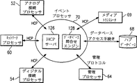
図8は、本発明の通信システムで用いられるイベントプロセッサのブロック図である。
図9は、本発明の通信システムで用いられるイベントプロセッサの状態図である。
図10は、本発明の通信システムで用いられる制御プロセッサ、管理プロセッサ、イベントプロセッサ、およびデータベースプロセッサのブロック図である。
図11は、本発明の通信システムで用いられる管理プロセッサのブロック図である。
図12は、本発明の通信システムで用いられるメディア変換のデータフロー図である。
図13は、本発明の通信システムで用いられるネットワークセンタのブロック図である。
図14は、本発明の通信システムのアドレス変換動作の例である。
図15は、本発明によって用いられる変換テーブルの例示である。
図16A? Bは、拡張アドレシングを行うために実行される変換の例である。
図17は、拡張アドレシング計画を実装するために本発明の一実施例によって用いられるシステムおよび方法の概略図である。
図18は、図17の実施例によって用いられる拡張アドレス完成テーブルの例示である。
図19は、図17の実施例による拡張アドレシングを行うために実行される変換の例である。
発明の詳細な説明
ネットワーク構造
図1は、マルチメディアネットワークベースの通信システム(全体的に10で示す。)のブロック図である。通信システム10は、いくつかのネットワークハブ12、14および16を含む。ネットワークハブ12、14および16は、通信ネットワーク18を通じて相互に接続されている。通信ネットワーク18は、例えば、高速データリンク、フレームリレーリンクあるいはその他の適当な高速データ通信ファシリティからなる。通信システム10は、さまざまなメッセージソース(送信元)からさまざまなメッセージデスティネーション(宛先)への通信トラフィックを処理しルーティングするように動作する。例えば、ハブシステム12は、図示のように、電話機22、メッセージングシステム(MS)24、従来のボイスメールシステム(VMS)26に接続されている。ボイスメールシステム26は、電話機38、ファクシミリ送信システム28および公衆メッセージングネットワーク30によって表される多数の電話端末に接続されている。公衆メッセージングシステム30は、例えば、加入者交換機キャリアによって公衆に提供されるメッセージングサービスからなる。さらに、ネットワークハブ14は、図示のように、私設システム32および電子メールファシリティ34に接続されている。私設システム32はそれ自体いくつかのメッセージングシステムを含む。ネットワークハブ14はまた、図示のように、電話機20および従来のボイスメールシステム36に直接接続されている。ボイスメールシステム36は、電話機38によって表される多数の電話機に接続されている。理解されるべき点であるが、直接接続として図示される通信接続は、実際には、私設および公衆通信ネットワークの一部である構内交換機や中央局交換機のような介在する交換ファシリティを含むことがある。
ネットワークハブ14はまた、図示のように、私設ローカルエリアネットワーク(全体的に31で示す。)に接続されている。ローカルエリアネットワーク31は、通信ゲートウェイ33を用いてネットワークハブ14と通信する。ローカルエリアネットワーク31は、さまざまなメッセージング動作をサポートするために用いられることが可能であるとともに、電子メール機能、ファクシミリ機能、音声機能あるいはビデオ機能を有するユーザステーションを接続することが可能である。通信システム10は、ゲートウェイ33およびネットワークハブ14を通じて、これらのすべてのシステムを他のメッセージングシステムと接続するために用いることが可能である。
同様に、ネットワークハブ16は、図示のように、メッセージングシステム40、私設システム42、およびファクシミリ送受信ファシリティ44に接続されている。私設システム42は、いくつかのメッセージングシステムを有する。ネットワークハブシステム12、14および16はまた、通信ネットワーク18を通じてネットワークセンタ37に接続されている。ネットワークセンタ37は、以下でさらに詳細に説明するように、ネットワーク10の動作をモニタする。情報プロバイダ39もまた、情報プロバイダ39からのデータおよびメッセージのトラフィックのための、通信システム10内へのゲートウェイとして設けられる。情報プロバイダ39は、例えば、掲示板情報や、ユーザの好みや人口統計あるいは情報の内容に基づいて通信システム10のユーザに配信される大衆配信情報サービスや広告メッセージを提供する。
以下で詳細に説明するように、通信システム10は、通信トラフィックの異種のソースおよび方式を統合し相互接続するとともに、それらの間でメッセージを変換するように動作する。通信システム10は、通信システムの全ユーザと各ユーザの通信プロファイルの普遍的なデータベースを管理する。通信プロファイルには、ユーザがメッセージを送受信することができるさまざまなメディアが含まれる。例えば、ある一人のユーザは、電子メールファシリティ、ボイスメールファシリティ、ファクシミリファシリティおよびビデオファシリティを用いて通信を制御および受信することが可能である。これらのファシリティはすべて、システム10のネットワークデータベース内の、そのユーザに対応するユーザプロファイルレコードにおいて指定される。後述するように、このデータベースのコピーが、図1のネットワークハブ12、14および16で例示される、システム10内の各ネットワークハブで管理される。大規模な統合ネットワーク機能では、数字アドレシングに基づいて大規模な分散ネットワークディレクトリを構築し管理するとともに、ユーザシステムのDTMFシグナリングおよび固有のプロトコルを利用してアクセスしなければならないという点で、音声メッセージングシステムとのインタフェースにより、個々のユーザプロファイルを管理することがさらに複雑になる。通信システム10はさらに、メディア、プロトコル、および言語の変換機能を有する。これにより、例えば、あるメディアで送信されたメッセージが別のメディアで受信されることが可能となる。例えば、電子メールメッセージは、デスティネーションユーザ側で、電子メールファシリティはないがファクシミリファシリティがある場合、あるいは、電子メール通信よりもファクシミリ送信を受信するほうを望む場合でも、送信することが可能となる。従って、通信システム10は、電子メールメッセージをファクシミリメッセージに変換し、そのメッセージを指定されたファクシミリファシリティへ送ることになる。大規模な統合ネットワーク機能では、相異なるメディアデスティネーションに対する数字アドレスを含み通信システムのユーザの数字アドレスによってアクセスされる大規模な分散ネットワークディレクトリを構築するとともに、ユーザシステムのDTMFシグナリングおよび固有のプロトコルを利用して配信しなければならないという点で、音声メッセージングシステムとのインタフェースにより、マルチメディアメッセージおよび代替ルーティングの処理はさらに複雑になる。さらに、音声メッセージングシステムの通信プロトコルには、マルチメディアメッセージに対して特殊な処理を要求し指定する能力がない。
本発明の利点を説明するために、通信システム10に接続され通信システム10によってサービスされるデータトラフィックのすべてのソースおよびデスティネーションを、それらが音声メールシステム、電子メールシステム、ファクシミリ送信ファシリティ、ビデオ送信ファシリティあるいはその他のデータ送信または受信ファシリティのいずれであるかにかかわらず、「メッセージングシステム」と呼ぶ。同様に、この説明のためには、このようなメッセージングシステムから受信されるデータは、その構成内容にかかわらず「メッセージ」と呼ぶ。例えば、通信システム10によって受信され、処理され配信されるメッセージは、音声メッセージ、電子メールメッセージ、ファクシミリもしくはビデオ送信またはメディアを組み合わせて合成メッセージを形成したものからなることが可能である。ここで、メッセージの「メディア」とは、メッセージが送受信される方式を指す。例えば、メッセージメディアには、音声、電子メール、ファクシミリもしくはその他のグラフィック画像、またはビデオが含まれる。さらに、メッセージの「プロトコル」とは、メッセージを通信システム10へ送信するメッセージングシステムによってメッセージを含むデータが符号化される方式、通信システム10を通る際にメッセージを含むデータが符号化される方式、および、デスティネーションメッセージングシステムがメッセージを理解するためにメッセージを含むデータが配送される前に符号化される方式を指す。「ユーザ」という用語は、ここでは、直接に、または、通信システム10に接続されたメッセージングシステムを通じて、通信システム10とインタフェースをとる人間を指す。
図1に示されるネットワークハブ12、14および16のようなネットワークハブは、通信システム10が、相異なるプロトコルを使用する多数の異種のメッセージングシステムと接続することを可能にするプロトコル変換ファシリティとして作用する。現在では、私設および公衆通信ならびにデータ伝送ファシリティによってメッセージングシステムを相互接続するために用いられる多数の通信プロトコルがある。通信システム10は、メッセージングシステムから、そのシステムに固有のプロトコルを用いてメッセージおよび管理情報を受信するように動作する。その後、メッセージおよび管理情報は、デスティネーションファシリティのプロトコルを用いてデスティネーションファシリティへ送信されることが可能である。いくつかの会社は、通信システム10によってサポートすることが可能な独自の情報配信プロトコル(そのようなプロトコルが利用可能であれば)を維持している。さらに、X.400メッセージング、SS7シグナリングならびにオーディオメッセージ交換仕様(AIMS(audio message interchange specification))のディジタルおよびアナログの両方のバージョンのようなパブリックドメインプロトコルもまた通信システム10によってサポートされる。例えば、X.400プロトコルは、現在用いられている実質的にすべての通信機能に対するサポートを含む。個々の機能セットは、通常、個々のメッセージングシステムによって用いられる機能に依存し、通常、X.400プロトコルによってサポートされる機能のサブセットを含む。通信システム10は、通信システム10に接続されるメッセージングシステムによって実装されるいかなる機能もサポートすることができるように自由度が高い。さらに、大規模な統合ネットワーク機能では、メッセージがDTMFシグナリングおよび数字アドレスを利用して配信されるという点で、音声メッセージングシステムとのインタフェースにより、マルチプロトコル変換機能の提供はさらに複雑になる。さらに、音声メッセージングシステムの通信プロトコルは、異種プロトコルへの変換を要求あるいは指定する能力がない。
本発明の通信システムはまた、ディレクトリ情報のためのさまざまな公衆および独自のプロトコルで動作する。以下でさらに詳細に説明するように、一部のメッセージングシステムは、アドレシングおよびルーティング情報のソースとして本発明の通信システムを使用するのみである可能性がある。このような場合、メッセージングシステムは、通信システム10に、目的とするデスティネーションに関する情報を提供する。すると、通信システム10は、メッセージングシステムが独立にデスティネーションと連絡をとり、メッセージを送信することができるように、特定のルーティング情報を返す。このような状況において、通信システム10とメッセージングシステムの間で渡されるディレクトリ情報は、通信システム10によって理解される公衆または独自のいくつかのディレクトリ情報プロトコルを使用することが可能である。大規模な統合ネットワーク機能では、数字アドレシングに基づいてアクセスされなければならないアドレスおよび配信情報を含む大規模な分散ネットワークディレクトリを構築し管理するとともに、この情報は、ユーザのメッセージングシステムのDTMFシグナリングおよび固有のプロトコルを利用して要求元のシステムへ配信されるという点で、音声メッセージングシステムとのインタフェースにより、ディレクトリアドレシングサービスを提供することはさらに複雑になる。
動作時には、ネットワークハブ12などのネットワークハブは、例えば、図1に示されるメッセージングシステム24を通じてメッセージを受信することになる。例として、メッセージングシステム24は、DTMFシグナリングのアナログAMISプロトコル形式を利用すると仮定する。さらに、メッセージングシステム24からのメッセージは、独自のディジタル通信プロトコルを利用する私設システム42によってサービスされる当事者宛であると仮定する。この場合、ネットワークハブ12は、メッセージングシステム24からアナログAMISプロトコルでメッセージを受信する。次に、ネットワークハブ12は、メッセージ内の情報をネットワーク伝送フォーマットに合うように変換し、変換されたメッセージを、通信ネットワーク18を通じてハブ16へ送信する。すると、ネットワークハブ16は、私設システム42によって理解される独自の通信プロトコルを用いてその情報を私設システム42へ送信する。このようにして、通信システム10は、メッセージがデスティネーションメッセージングシステムへ送信されるメディアを変換するように作用するのみならず、異種の通信プロトコルをサポートすることによって、異なる独自のメッセージングシステム間のメッセージングを提供するようにも作用する。本発明の通信システムは、メッセージのすべてのルーティングおよび処理のために共有内部プロトコルを使用する。従って、本発明の通信システムは、MIME(Multipurpose Internet Mail Extension)などのような新たな通信プロトコルが広まるのにも容易に適応することができる。これらの新たなプロトコルを利用するシステムとインタフェースするために要求されるネットワークハブは、新たなプロトコルを内部プロトコルに変換するだけでよい。こうして、通信システムの動作は全体として、無制限の新しいプロトコルの追加をサポートすることができる。
通信システム10内のネットワークハブシステムは、相互に、および、ネットワークセンタ37と常に通信して、通信システム10内のメッセージの状態について更新を行うとともに、さらに、各ネットワークハブ内のユーザデータベースに記憶されているユーザプロファイル情報についても更新する。ネットワークセンタ37は、これらのデータベースおよび状態の更新を受信し、それらの更新を、通信システム10内の残りのハブへ送信する。ハブ間で常に通信していることにより、これらの更新は、ユーザプロファイルの普遍的なディレクトリと、通信システム10内のすべてのメッセージの状態に関する常に変化する情報とを提供する。大規模な統合ネットワーク機能では、大規模な分散ネットワークディレクトリが構築され、通信システムのユーザの数字アドレスによってアクセスされなければならないという点で、音声メッセージングシステムとのインタフェースにより、ユーザプロファイル情報およびメッセージ追跡のアクセスおよび更新はさらに複雑になる。
後述するように、通信システム10内の相互接続されたネットワークハブはまた、通信システム10に接続されるメッセージングシステムに利用可能な大量の仮想記憶を提供する。このようにして、大規模な掲示板やその他の共有情報を、いずれのネットワークハブに記憶することも可能であり、また、通信システム10に接続されたメッセージングシステムで即時に利用可能である。大規模な統合ネットワーク機能では、DTMFシグナリング、数字アドレシングおよびディレクトリ情報を利用する要求元のシステムに対する、ユーザシステムの固有のプロトコルで送信される数字アドレスおよびアクセス/配信情報を含む大規模な分散ネットワークディレクトリを構築し管理しなければならないという点で、音声メッセージングシステムとのインタフェースにより、掲示板やその他の共有情報サービスを提供することはさらに複雑になる。
ネットワークハブアーキテクチャ
図2は、本発明のネットワークハブで用いられるさまざまなソフトウェアモジュールの相互関係のブロック図である。図2は、図1に関して前に説明したネットワークハブ12、14および16のような特定のネットワークハブ内で機能するさまざまなモジュールを示す。図2において、接続プロセッサ52および54は、この特定ネットワークハブに接続されたメッセージングシステムと相互作用する。例えば、アナログ接続プロセッサ52は、DTMFシグナリングを使用する音声メッセージングシステムによって利用されるアナログ通信プロトコルのようなアナログ通信プロトコルを用いる外部メッセージングシステムと通信する。同様に、ディジタル接続プロセッサ54は、ディジタル通信プロトコルを使用する外部メッセージングシステムと通信する。図2には接続プロセッサ52および54のみが示されているが、特定のネットワークハブに接続されたメッセージングシステムの数に対して十分な数だけこれらのそれぞれの接続プロセッサがあると理解すべきである。接続プロセッサ52および54は、図2に示される内部インタフェース56を通じて、例えばTCP/IP(Transport Control Protocol/Internet Protocol)を用いて残りのソフトウェアシステムと通信する。内部インタフェース56は、特定のネットワークハブ内で動作するソフトウェアシステム内のすべてのモジュール間の主な通信リンクとして作用する。内部インタフェース56はまた、メッセージ格納58へのアクセスを提供するファイルサーバ59に接続されている。メッセージ格納58は、例えば、ハードディスクドライブのような大規模ディジタル記憶メディアからなる。メッセージ格納58は、ネットワークハブに接続されたメッセージングシステムとの間で送受信されるメッセージを収容する。メッセージのメディアあるいはフォーマットを変換しなければならないときには、メディアトランスレータ69が使用される。メディアトランスレータ69は、メッセージ格納58に記憶されているメッセージに対してメディアあるいはその他の形式の変換を実行する。大規模な統合ネットワーク機能では、数字アドレシング法を利用する分散ネットワークディレクトリにより変換パラメータにアクセスしなければならない点、および、音声メッセージングシステムの通信プロトコルはメディア変換サービスを要求あるいは指定することができないという点で、音声メッセージングシステムとのインタフェースにより、メディアおよびその他の変換サービスを提供することはさらに複雑になる。
ネットワークプロセッサ60もまた内部インタフェース56に接続されている。ネットワークプロセッサ60は、特定のネットワークハブを他のネットワークハブおよびネットワークセンタ37に接続する外部インタフェース62にも接続されている。ネットワークプロセッサ60は、他のネットワークハブへのメッセージを収集および分配する。他のネットワークハブと通信するために、ネットワークプロセッサ60は、例えば、SMTP(simple message transport protocol)およびMIMEプロトコルを使用する。
管理プロセッサ64もまた、内部インタフェース56および外部インタフェース62に接続されている。管理プロセッサ64は、ネットワークセンタ37および特定ネットワークハブと通信し、特定ネットワークハブ内のメッセージトラフィックをモニタおよび管理するように動作する。大規模な統合ネットワーク機能では、音声メッセージングシステムのユーザの数字アドレスによってメッセージにアクセスしメッセージを追跡しなければならないという点で、音声メッセージングシステムとのインタフェースにより、ユーザのメッセージおよび情報を追跡することはさらに複雑になる。
一群の制御プロセッサ66が、外部インタフェース62とハブデータベース68の間に接続されている。図3に関してさらに詳細に後述するように、制御プロセッサは、メッセージルータ72、接続マネージャ74、データレプリケータ76および管理イベントマネージャ78を有する。一般に、制御プロセッサ66は、ネットワークハブの動作を制御するとともに、ハブデータベース68に記憶されている情報を管理し操作するように動作する。ハブデータベース68はまた、イベントプロセッサ70を通じて内部インタフェース56を含む通信システムの残りの部分に接続され操作される。イベントプロセッサ70は、ネットワークハブ要素の実時間制御を提供する。イベントプロセッサ70は、ディレクトリサービス要求、識別確認要求、アナログ、ディジタルおよびネットワーク接続要求、メッセージ配信イベントならびに管理イベントキューに応答する。大規模な統合ネットワーク機能では、音声メッセージングシステムのユーザの数字アドレスを含む大規模な分散ネットワークディレクトリを構築し管理しなければならないという点で、音声メッセージングシステムとのインタフェースにより、メッセージルーティングのような制御プロセッサの動作、および、ディレクトリサービス要求のようなイベントプロセッサの動作は、ユーザのメッセージおよび情報を追跡することはさらに複雑になる。
ネットワークハブは、個々のネットワークハブによってサービスされるトラフィックの量に応じて、さまざまなハードウェアプラットフォームを用いて実装することが可能である。一般に、接続プロセッサは、通信周辺機器カードによってサービスされるパーソナルコンピュータプラットフォームに存在する。制御プロセッサおよびデータベースファシリティは、適当なワークステーションプラットフォーム上に実装することが可能である。これらのさまざまなディスクリートなハードウェアプラットフォームはすべて、ローカルエリアあるいはワイドエリア(広域)ネットワークシステムを用いて相互に通信することが可能である。
図3は、ネットワークハブ内で動作するさまざまなソフトウェアモジュール内でのさまざまな種類のデータのルーティングおよび交換を示すデータフロー図である。図2に関して説明した多くのファシリティが図3のデータフロー図にさらに詳細に示されている。例えば、制御プロセッサ66は、構成要素に分解されている。図3は、メッセージルータ72、接続マネージャ74、データレプリケータ76および管理イベントマネージャ78を示している。図3に示されるように、このような制御プロセッサ66はそれぞれ、例えばSQL/蓄積手続きを含むデータベースアクセス手続きを通じてハブデータベース68と相互作用する。本質的には、これらのさまざまなソフトウェアモジュールは、例えばTCP/IPソケットや遠隔手続き呼出しを含む通信メカニズムを通じて制御プロセッサ66と相互作用することが可能である。
イベントプロセッサ70は、適当なハブ制御プロトコル(HCP(hub control protocol))を用いて、ネットワークプロセッサ60、アナログ接続プロセッサ52、メディアトランスレータ69、およびディジタル接続プロセッサ54と相互作用する。ハブ制御プロトコルは、クライアント? サーバ型、要求? 応答型の通信を提供する適当なプロセス間通信メカニズムからなることが可能である。ハブ制御プロトコルは、例えば、遠隔手続き呼出しやTCP/IPソケットに基づく。メディアトランスレータ69は、ファイルサーバ59を通じてメッセージ格納58内のメッセージにアクセスし、前述のようにメディアおよびフォーマット変換を実行する。
管理プロセッサ64は、例えばSNMPプロキシやSNMPサブエージェント通信からなる適当な管理プロトコルを用いて、ネットワークプロセッサ60、アナログ接続プロセッサ52、ディジタル接続プロセッサ54およびイベントプロセッサ70と相互作用する。ネットワークプロセッサ60、アナログ接続プロセッサ52、およびディジタル接続プロセッサ54は、例えばMIMEを利用するメッセージの蓄積および取得によりファイルサーバ59を通じてメッセージ格納58と相互作用する。最後に、ネットワークプロセッサ60、アナログ接続プロセッサ52、ディジタル接続プロセッサ54、管理プロセッサ64およびデータレプリケータ76は、これらのファシリティに接続されたデスティネーションに適したメッセージングプロトコルあるいはディレクトリプロトコルを用いて、他のネットワークハブ、メッセージングシステム、あるいはネットワークセンタ37と通信する。大規模な統合ネットワーク機能では、メッセージングシステムのユーザの数字アドレスを含む大規模な分散ネットワークディレクトリを構築し管理しなければならないという点で、音声メッセージングシステムとのインタフェースにより、ネットワークハブ動作はさらに複雑になる。
ネットワークハブ記憶装置
各ネットワークハブは、前述の2つのデータ記憶装置を含む。各ネットワークハブは、ハブデータベース68およびメッセージ格納58を含む。前述のように、メッセージ格納58は、発信および着信メッセージを記憶し、ファイルサーバ59を通じてアクセスされるように作用する。ハブデータベース68は、料金情報、ディレクトリサービス要求、識別確認、ルーティング情報およびキューサービス情報の記憶のための高性能データベースを含む。大規模な統合ネットワーク機能では、通信システムのユーザの数字アドレスを含む大規模な分散ネットワークディレクトリを構築し管理しなければならないという点で、音声メッセージングシステムとのインタフェースにより、ネットワークハブデータベースはさらに複雑になる。後述するように、ハブデータベース68は、発信および着信メッセージを含むさまざまな管理キューを有する。これらのキューは、実際のメッセージを含むのではなく、メッセージ格納58に記憶されているメッセージの配信情報を含む。分散しているソフトウェアモジュールは、ネットワークファイルシステムあるいはその他の適当なデータ転送プロトコルを用いることによりファイルサーバ59を通じてメッセージ格納58にアクセスすることになる。
ハブデータベース68は、高性能データベースを含む。ネットワークハブの動作に自由度を提供するために、ハブデータベース68へのアクセスは問合せリクエスタによって提供される。問合せレスポンダが、ネットワーク遠隔手続き呼出しを通じてさまざまなソフトウェアモジュールから抽象的な問合せを受信する。これらの呼出しは問合せレスポンダによって変換され応答される。このアーキテクチャを用いることによって、ハブデータベース68は、単に問合せレスポンダを変えることによって変更することができる。
アナログ接続プロセッサ52、ディジタル接続プロセッサ54およびネットワークプロセッサ60は、必要に応じてファイルサーバ59を用いて、メッセージ格納58に記憶されているメッセージにアクセスする。メッセージ格納58内のメッセージは、ファイルサーバ59を通じてメディアトランスレータ69によってもアクセスされる。メディアトランスレータ69は、例えば、テキスト? 音声合成システムを用いて電子メールメッセージから音声メッセージへの変換のように、メディア間でメッセージの変換を実行する。メディアトランスレータ69の動作については後で図11を参照してさらに詳細に説明する。
アナログ接続プロセッサ
図4は、前に図2および図3に関して説明したアナログ接続プロセッサ52の動作のブロック図である。本発明の一実施例によれば、アナログ接続プロセッサ52は、アナログAMISのようなアナログネットワーキングプロトコルを用いてアナログ接続されたメッセージングシステムからのさまざまな形式のメッセージを収集し分配する。大規模な統合ネットワーク機能では、通信システムは、標準的な電話インタフェースをサポートすること、DTMFシグナリングを利用する要求元のシステムへの数字アドレシングおよびアクセス/配信情報をサポートすることが必要とされるのに加えて、接続されている音声メッセージングシステムの固有のプロトコルをサポートしなければならないという点で、音声メッセージングシステムとのインタフェースにより、アナログ接続プロセッサの機能はさらに複雑になる。アナログ接続プロセッサ52は、例えばUNIX、Windows NT、あるいはSOLARISオペレーティングシステムが動作する486? ISAバスのパーソナルコンピュータシステムからなるハードウェアプラットフォームで動作する。このハードウェアプラットフォームは、複数の音声、ファクス、およびモデム処理カードや、他の形式のアナログデータ転送を処理する他の形式のインタフェースカードを含むことが可能である。このハードウェアプラットフォームはまた、特定のネットワークハブ内の残りのファシリティに接続するためのイーサネットアダプタのような高性能ネットワークアダプタカードを含むことが可能である。アナログ接続プロセッサ52のハードウェアプラットフォームはまた、UNIXオペレーティングシステムのようなオペレーティングシステムファイルと、受信および送信メッセージを保持するのに十分な一時記憶スペースとを記憶するためのディスクドライブ記憶装置を含む。
図4を参照すると、アナログ接続プロセッサ52は、3つの内部モジュールを含むように示されている。メッセージモジュール80は、アナログ接続プロセッサ52がファイルサーバ59を通じて前述のメッセージ格納58と通信することを可能にする。アナログインタフェースモジュール82は、アナログメッセージングプロトコルを用いて、アナログ接続プロセッサ52とメッセージングシステムの間の通信リンクを提供する。制御モジュール84は、アナログ接続プロセッサ52が管理プロトコルを用いて管理プロセッサ64と通信することを可能にする。制御モジュール84はまた、ハブ制御プロトコルを用いて前述のようにイベントプロセッサ70と通信する。
図5は、アナログ接続プロセッサ52の動作を示す状態図である。処理はブート状態86から開始する。この状態には、アナログ接続プロセッサ52の起動時、または、ハードウェアもしくはソフトウェアリセット条件下で自動的に入る。オペレーティングシステムおよびアプリケーションソフトウェアがアナログ接続プロセッサ52に正常にロードされた後、アナログ接続プロセッサ52はブート状態86を出てイベントプロセッサポーリング状態88に移る。イベントプロセッサポーリング状態は、アナログ接続プロセッサ52が前述のイベントプロセッサ70からアナログ接続プロセッサが実行すべきタスクについての指示を待機しているアイドル状態である。イベントプロセッサポーリング状態88の間にイベントプロセッサ70がアナログ接続プロセッサ52に対してメッセージングシステムとの接続を作成するよう指示した場合、アナログ接続プロセッサ52は、状態88を出て、図5に示される接続作成状態90に移る。状態90において、アナログ接続プロセッサ52は、接続を確立し、接続が作成されたことを確認する。
イベントプロセッサ70はまた、アナログ接続プロセッサ52に対して、イベントプロセッサポーリング状態88の間に、メッセージングシステムからの問合せを待機するよう指示することも可能である。この場合、アナログ接続プロセッサ52は、図5に示される接続待機状態92に移る。接続待機状態92において、アナログ接続プロセッサ52は、所定時間が経過するまで、または、発呼側メッセージングシステムあるいはネットワークファシリティとの接続が形成されるまでとどまる。イベントプロセッサ70はまた、アナログ接続プロセッサ52を、イベントプロセッサポーリング状態88からアイドル状態94に移らせることもできる。アイドル状態94は、発信呼用に通信ポートを予約するために、あるいは、アナログ接続プロセッサ52が新たな呼を受け付けないようにするために、制御プロセッサ66およびイベントプロセッサ70によって使用される。一般に、ネットワークハブにとって利用可能な通信ポートのうちの所定の割合がアイドル状態94に維持され、メッセージあるいはディレクトリ情報を配信するために発信接続を形成するためのプールを提供する。アナログ接続プロセッサ52は、所定時間が経過するまでアイドル状態94にとどまり、その後、アナログ接続プロセッサ52はイベントプロセッサポーリング状態88に復帰する。
接続作成状態90において接続が確立され認証された後、アナログ接続プロセッサ52は、プロトコルマスタ状態96に移る。プロトコルマスタ状態96は、メッセージあるいはディレクトリ情報がメッセージングシステムへ送信されるメッセージ送信状態である。プロトコルマスタ状態96に入ると、アナログ接続プロセッサ52は、制御プロセッサ66によって提供されるすべてのメッセージおよびディレクトリ情報を、接続されているメッセージングシステムへ送信し続ける。接続中のいくつかの時点で、アナログ接続プロセッサ52は、プロトコルスレーブ状態98に移ろうとする。この状態において、アナログ接続プロセッサ52は、メッセージ、ディレクトリ情報、あるいはその他のデータをメッセージングシステムから受信することが可能である。そのときに、メッセージ、ディレクトリ情報あるいはデータを受信する必要がない場合、アナログ接続プロセッサ52は、プロトコルマスタ状態96から接続終了状態99に移る。接続終了状態99において、メッセージングシステムとの接続は終了する。その後、処理は、イベントプロセッサポーリング状態88に復帰する。
プロトコルスレーブ状態98は、アナログ接続プロセッサ52のメッセージ受信状態である。プロトコルスレーブ状態98の間、アナログ接続プロセッサ52は、メッセージングシステムからのメッセージ、ディレクトリ情報およびデータ送信を受信し検証する。アナログ接続プロセッサ52は、メッセージ、ディレクトリ情報、あるいはその他のデータがメッセージングシステムによってさらに提供されなくなるまで、プロトコルスレーブ状態98にとどまる。その時点で、アナログ接続プロセッサ52は、前述の接続終了状態99を通ってイベントプロセッサポーリング状態88に復帰する。
ディジタル接続プロセッサ
ディジタル接続プロセッサ54は、前述のアナログ接続プロセッサ52と同様に動作する。図6は、ディジタル接続プロセッサ54内に含まれる機能モジュールを示すブロック図である。ディジタル接続プロセッサ54は、ファイルサーバ59を通じてディジタル接続プロセッサ54とメッセージ格納58の間の通信を行うメッセージモジュール100を含む。ディジタル接続プロセッサ54はまた、ディジタル接続プロセッサ54とメッセージングシステムの間の通信を行うディジタルインタフェースモジュール102を含む。めっせーじんぐしすてむは、ディジタルAMIS、SMTP? MIME、cc:Mailのようなディジタルプロトコルや、インターネットおよびMCI MAILのような外部サービスプロバイダを利用する。
ディジタル接続プロセッサ54はさらに、ハブ制御プロトコルを用いてイベントプロセッサ70との通信を行う制御モジュール104を含む。制御モジュール104はまた、管理プロトコルを用いて管理プロセッサ64と通信する。
ディジタル接続プロセッサ54は、ディジタルネットワークプロトコルを用いて、ディジタル接続されたメッセージングシステムから、音声、ファクス、電子メールおよびその他のメディアのメッセージを収集し分配する。本発明の一実施例によれば、ディジタル接続プロセッサ54はまた、X.500やその他のディジタルディレクトリプロトコルのようなディジタルディレクトリプロトコルを用いてディレクトリ更新サービスを提供し受信する。ディジタル接続プロセッサ54は、例えばUNIX、Windows NT、あるいはSOLARISオペレーティングシステムが動作する486? ISAバスのパーソナルコンピュータシステムあるいはSPARCシステムからなるパーソナルコンピュータプラットフォーム上に実装される。ディジタル接続プロセッサ54のプラットフォームは、ダイヤルインディレクトリサービスやメール送信、およびディレクトリ情報問合せのための従来のモデムや、図2に関して前述した広域ネットワークイーサネット接続およびローカルエリアネットワーク接続50を提供するイーサネット接続のようなさまざまなインタフェースシステムをサポートする。アナログ接続プロセッサ52と同様に、ディジタル接続プロセッサ54はまた、UNIXオペレーティングシステムのようなオペレーティングシステムファイルと、受信および送信メッセージを一時的に保持するのに十分な記憶領域とを記憶するためのディスクドライブファシリティを含む。
動作時には、ディジタル接続プロセッサ54は、図6に関して説明した、アナログ接続プロセッサ52の動作と同一の状態を使用する。
メッセージフォーマット
アナログ接続プロセッサ52およびディジタル接続プロセッサ54はいずれも、受信メッセージを受け付け検証する。大規模な統合ネットワーク機能では、通信システムは、標準的な電話インタフェースをサポートしなけれればならないのに加えて、一般に長く数分にわたるディジタル化されたアナログオーディオ信号のメッセージをサポートしなければならないという点で、音声メッセージングシステムとのインタフェースにより、内部メッセージフォーマットはさらに複雑になる。このようなメッセージの配信には、メッセージの翻訳あるいは変換が伴う。例えば、メッセージは、別のメディアに変換される必要が生じる可能性がある。受信されるデータ通信は、あるフォーマットから別のフォーマットへ変換される必要が生じる可能性がある。図11に関してさらに詳細に後述するように、このような変換および翻訳は、メディアトランスレータ69によって実行される。一部分は、これらの機能は、受信されるすべてのメッセージデータを標準的なメッセージラッパでカプセル化して、通信システム10内における転送および蓄積のためのメッセージを形成することによって実現される。このラッパは、例えばMIMEカプセル化プロトコルに基づく。通信システム10によって受信される多くのメッセージは既にメッセージラッパを含む。このようなメッセージもまた、標準的な内部メッセージフォーマットに変換される。このフォーマットは、メッセージ内の各メッセージメディアに、送信者によって提供されるアドレシング情報によりタグおよびラベルをつける。各メッセージは、メッセージが送信された時刻からなるデータフィールドを含む。この時刻は、メッセージ送信プロトコルによって提供されるか、あるいは、本発明の通信システムによって提供される。各メッセージはまた、「from」フィールドを含む。このフィールドでは、メッセージ送信者のネットワーク識別とメッセージ送信者のメッセージングシステム識別子がインターネット形式のアドレスに結合されている。各メッセージはまた、「to」フィールドを含む。このフィールドでは、目的とする受信者のネットワーク識別および目的とするデスティネーションのメッセージングファシリティがインターネット形式のアドレスに結合されている。各メッセージはまた、メッセージの管理目的の追跡およびその他の管理目的で用いられる一意的なメッセージ識別フィールドを収容する。
後述の秘密および緊急のようなさまざまな配信機能は通常、メッセージ自体においては識別されない。むしろ、このような要求の存在は、受信されたメッセージがハブデータベース68内のメッセージキューに入ったときに、制御プロセッサ66へ送信される。
ネットワークプロセッサの動作
図7は、ネットワークプロセッサ60によって用いられる機能モジュールを示すブロック図である。ネットワークプロセッサ60は、ネットワークプロセッサ60が、図7に示されるイベントプロセッサ70、管理プロセッサ60、および他のネットワークプロセッサ122と通信することを可能にする制御モジュール120を含む。ネットワークプロセッサ60はまた、ファイルサーバ59を通じてメッセージ格納58との通信を行うメッセージモジュール124を有する。ネットワークプロセッサ60は、本発明の一実施例では、アナログ接続プロセッサ52およびディジタル接続プロセッサ54と同様のスタンドアローン型のハードウェアプラットフォームであることも可能であるが、ネットワークプロセッサ60は、内部インタフェース56に接続し、メッセージ格納58、ファイルサーバ59、およびハブデータベース68のような残りの記憶ファシリティを含む中央サーバ上のタスクとして実装される。ネットワークプロセッサ60は、3つのデータパスを用いてネットワークハブ内の他のリソースと通信する。ネットワークプロセッサ60とイベントプロセッサ70の間の制御および問合せ情報の交換については、ハブ制御プロトコルを用いて交換される。運用モニタリング統計および状態情報は、管理プロトコルを用いて管理プロセッサ64との間で交換される。メッセージは、ファイルサーバ59を用いてメッセージ格納58との間で渡される。
ネットワークプロセッサ60は、通信システム10内の他のネットワークハブへのメッセージを収集し配信する。動作時には、ネットワークプロセッサ60は、図6に関して説明した、アナログ制御プロセッサ52の動作と同一の状態を使用する。大規模な統合ネットワーク機能では、通信システムのユーザの数字アドレスを含む大規模な分散ネットワークディレクトリを構築し管理しなければならないという点で、音声メッセージングシステムとのインタフェースにより、ネットワークプロセッサの動作はさらに複雑になる。
イベントプロセッサの動作
図8は、イベントプロセッサ70の機能要素を示すブロック図である。イベントプロセッサ70は、アナログ接続プロセッサ52、ネットワークプロセッサ60およびディジタル接続プロセッサ54から遠隔手続き呼出しを受信するハブ制御プロトコル(HCP)サーバ126を含む。イベントプロセッサ70はまた、アナログ接続プロセッサ52、ネットワークプロセッサ60およびディジタル接続プロセッサ54からの遠隔手続き呼出しに対してサービスするためにハブデータベース68に対する問合せおよび操作を行うように動作するデータベース問合せエンジン128を含む。イベントプロセッサ70はまた、管理プロトコルを用いて管理プロセッサ64と相互作用する。イベントプロセッサ70はまた、メディアトランスレータ69と相互作用して、ファイルサーバ59を用いてメッセージ格納58に対してメディアトランスレータ69によってアクセスされたメッセージの変換を指示する。大規模な統合ネットワーク機能では、通信システムのユーザの数字アドレスを含む大規模な分散ネットワークディレクトリを構築し管理しなければならないという点で、音声メッセージングシステムとのインタフェースにより、イベントプロセッサの動作はさらに複雑になる。
図9は、イベントプロセッサ70の動作を示す状態図である。イベントプロセッサ70内での処理はブート状態130から開始する。ブート状態130には、通信システムの起動またはリセット時に入る。適当なアプリケーション、プログラムおよびオペレーティングシステムがロードされると、イベントプロセッサ70の動作はブート状態130から問合せ取得状態132に移る。問合せ取得状態132において、イベントプロセッサ70は、アナログ接続プロセッサ52、ネットワークプロセッサ60またはディジタル接続プロセッサ54からの遠隔手続き呼出し、あるいは、管理プロセッサ64からの管理プロトコル問合せを待機し続ける。そのような問合せを受信すると、イベントプロセッサ70は、問合せ処理状態134に移る。問合せ処理状態134において、データベース問合せエンジン128は、データベースアクセス手続きを用いてハブデータベース68にアクセスする。その応答が、問合せ処理状態134においてハブデータベース68から受信されると、イベントプロセッサ70は応答送信状態136に移る。応答送信状態136において、適当な応答が、前述のプロセッサ52、54、60、または64のうちのいずれかに転送される。その後、イベントプロセッサ70は問合せ取得状態132に復帰し、次の要求がイベントプロセッサ70に転送されるまで、イベントプロセッサ70は問合せ取得状態132にとどまる。
制御プロセッサのアーキテクチャ
図10に示されるように、図3に示した制御プロセッサ66はそれぞれ、共通のアーキテクチャを共有する。メッセージルータ72、接続マネージャ74、データレプリケータ76、および管理イベントマネージャ78はそれぞれ、ネットワークハブの動作のための一群のタスクを制御する。ネットワークハブの全体的制御は、ハブデータベース68の制御、特に、ハブデータベース68内に含まれるメッセージキューおよび管理イベントキューの制御を通じて達成される。このようにして、メッセージキューおよび管理イベントキューに記憶されたイベントに優先順位をつけ、イベントプロセッサ70によって読み出されるこれらのキュー内のエントリを作成し操作することによって、制御が達成される。イベントプロセッサ70は、ネットワークハブの実際の実時間エンジンである。
図10は、制御プロセッサ66、管理プロセッサ64およびイベントプロセッサ70のそれぞれのアーキテクチャと、これらのエンティティがハブデータベース68のさまざまな部分と相互作用する様態を示すブロック図である。各制御プロセッサは、ハブコントローラモジュール138およびデータベース問合せエンジン140を含む。ハブコントローラ138は、ハブデータベース68に記憶されているタスクを管理し、データベースアクセス手続きを用いてデータベース問合せエンジン140を通じてハブデータベース68と通信する。
メッセージルータの動作
メッセージルータ72は、ハブコントローラ138およびデータベース問合せエンジン140を含む。メッセージルータ72は、着信メッセージキュー142、発信メッセージキュー146、およびメッセージシステムデータベース147と相互作用する。一般に、メッセージルータ72は、メッセージシステムデータベース147からの情報を用いて、ネットワークハブを通る各メッセージの次のデスティネーションを判定する。前述のように、メッセージ自体は実際にはメッセージ格納58に記憶され、ファイルサーバ59を用いてアクセスされる。着信メッセージキュー142および発信メッセージキュー146は、メッセージ格納58内のメッセージの位置を示すメッセージレコードと、各メッセージのソースおよびデスティネーションを記憶する。イベントプロセッサ70によってメッセージレコードが着信メッセージキュー142に入れられた後、メッセージルータ72はそれを読み出す。その後、メッセージルータは、そのメッセージレコードに対応するメッセージの次のデスティネーションを判定し、新たなメッセージレコードを作成して、そのメッセージを発信メッセージキュー146に入れる。
メッセージルータ72はまた、メッセージに優先順位をつけ、将来配信する場合に、メッセージを遅延させる。一般に、メッセージは、優先順位に従って格付けされ配信される。本発明の通信システム10を効率的に使用するためには、メッセージングトラフィックをおよそ一定量に整形する能力が要求される。このトラフィック整形は、ネットワークの負荷が減るまで必要に応じてメッセージルータ72が選択的にメッセージを遅延させることによって達成される。これを実現するため、メッセージルータ72は、各メッセージに内部優先度をつける。通信システムの内部優先度は、送信されたメッセージによって指定される緊急性と、メッセージが配信のために受信されてからどのくらい経過しているかの両方によって設定される。大規模な統合ネットワーク機能では、通信システムのユーザの数字アドレスを含む、ハブデータベース68のための大規模な分散ネットワークディレクトリを構築し管理しなければならないという点で、音声メッセージングシステムとのインタフェースにより、メッセージルータの動作はさらに複雑になる。
接続マネージャの動作
接続マネージャ74もまた、ハブコントローラ138およびデータベース問合せエンジン140を含む。接続マネージャ74は、発信メッセージキュー146内のメッセージレコードを読み出し、発信メッセージキュー146内の各メッセージレコードに対してサービスするために形成しなければならない接続の性質を判定する。これらの接続に対応する接続キューレコードが形成され、ハブデータベース68内の接続キュー141に入れられる。接続マネージャ74はまた、発信管理イベントキュー143から管理イベントレコードを読み出し、発信管理イベントキュー143内の管理イベントレコードに対してサービスするためにネットワーク内の接続が要求されるかどうかを判定する。ネットワーク接続が要求される場合、レコードが同様に形成され接続キュー141に入れられる。大規模な統合ネットワーク機能では、通信システムのユーザの数字アドレスを用いて、着信および発信メッセージキュー内のメッセージレコード、管理イベントキュー内の管理イベントレコード、および接続キュー内の接続キューレコードの構築、管理、およびアクセスをしなければならないという点で、音声メッセージングシステムとのインタフェースにより、接続マネージャの動作はさらに複雑になる。
接続マネージャ74は、各ネットワークハブ、ネットワークセンタ37、および各メッセージングシステムの間の接続を制御する。接続マネージャ74は、ハブデータベース68の発信メッセージキュー146および発信管理イベントキュー143内の各メッセージおよび管理イベントに対して接続キューレコードを作成する。接続マネージャ74は、通常の接続を管理するとともに、いつ複数の接続が必要とされるか、および、失敗した接続をいつ再試行すべきかを判定する。接続マネージャ74は、発信メッセージキュー146または発信管理イベントキュー143内のレコードによってトリガされる。あるいは、接続マネージャ74は、ネットワークハブ内のすべてのキューの周期的スキャンを行い、イベントの数と、発生待機中のイベントの優先度に基づいて接続キュー141の優先順位の付け直しをすることも可能である。
前述のように、接続マネージャ74は、接続を形成する必要があるデスティネーションのリストを含む接続キュー141を管理する。これらの接続は、特定の時刻に、あるいは、必要に応じて、メッセージの数、特定のキュー内の最も古いメッセージ、または接続が形成された最終時刻に基づく優先度に従って、スケジューリングされることが可能である。接続キュー141は、新たに利用可能な通信ポートに対する次の動作を判定するために、イベントプロセッサ70によってアクセスされる。接続キュー141は、接続マネージャ74によって、接続優先度表示により周期的に更新される。各接続キューレコードは、接続キュー141内の最高優先度メッセージと接続キュー141内のメッセージ数のカウントに基づく全体優先度表示でマークされる。
これらの優先度表示は、Immediate(即時)、High(高)、Normal(通常)、またはLow(低)である。Immediateは、与えられたデスティネーションに対して接続キュー141内にスケジューリングされているイベントの期限が過ぎていることを示す。Highは、与えられたデスティネーションに対してスケジューリングされているイベントが高い内部優先度を有し、デスティネーションへの接続は接続が利用可能になり次第すくに形成されるべきであることを示す。接続が確立されHigh優先度のメッセージが送信されると、その接続上の負荷が許容する場合には他のメッセージも送信可能である。Normal優先度は、High優先度でスケジューリングされたイベントが接続キュー141に存在せず、少なくとも1つのNormal優先度のイベントが接続キュー141に存在することを示す。接続マネージャは、接続が解放され、未決のHigh優先度のイベントが接続キュー141にない場合に、接続を確立する。接続が確立されNormal優先度のメッセージが送信された後、負荷が許容する場合に、Low優先度のイベントが処理されることが可能となる。Low優先度表示は、Low優先度のスケジューリングされたイベントのみが接続キュー141に存在するときに生じる。接続マネージャは、接続が解放され、Normal、High、あるいはImmediate優先度の接続が要求されていない場合に、接続を確立する。Low優先度のメッセージは、所定時間(例えば2時間)接続キュー141にとどまった場合にNormal優先度に昇格する。
通信システム10の効率的動作は、接続マネージャ74による効率的なキュー管理による。アナログ接続プロセッサ52、ディジタル接続プロセッサ54あるいはネットワークプロセッサ60のような接続プロセッサは同じ接続上で役割を変えることができるため、ネットワークハブ間の接続は、交換される全トラフィック量によって優先順位付けされる。さらに、接続が不足した場合、相互作用するネットワークハブは相互に連絡して、接続が形成される可能性を増大させようと試みる。この相互作用を行うため、予約技術が実装される。接続マネージャ74は、接続キュー141に配信情報レコードを追加することに加えて、接続キュー141内に接続レコードを作成するとき、同様のエントリが、デスティネーションメッセージングシステムに接続されたリモートネットワークハブに送信される。このようにして、ローカルネットワークハブとリモートネットワークハブはいずれも接続が形成されなければならないことを知り、連絡試行がいずれかのネットワークハブによって開始されることが可能となる。メッセージ接続が確立されると、メッセージキューの通常処理を通じて、または、ネットワークハブが相互に連絡を試みることによって、両方のネットワークハブはその接続を用いてすべてのメッセージを相互に送信することができる。
管理イベントマネージャの動作
管理イベントマネージャ78は、メッセージルータ72がメッセージレコードを処理するのと同様に管理イベントを処理する。管理イベントマネージャ78は、ハブコントローラ138およびデータベース問合せエンジン140を含む。管理イベントマネージャ78は、着信管理イベントキュー145から、イベントプロセッサ70によって入れられたエントリを読み出す。その後、管理イベントマネージャ78は、管理イベントメッセージを通信システム10内の別のネットワークハブへ送信しなければならないかどうか、あるいは、メッセージをネットワークセンタ37へ送信しなければならないかどうかを判定する。管理イベントメッセージをこれらのロケーションのいずれかに送信しなければならない場合、発信管理イベントキュー143にエントリが形成される。大規模な統合ネットワーク機能では、通信システムのユーザの数字アドレスを用いて管理イベントキュー内の管理イベントレコードの構築、管理、およびアクセスをしなければならないという点で、音声メッセージングシステムとのインタフェースにより、管理イベントマネージャの動作はさらに複雑になる。
データレプリケータの動作
前述のように、データレプリケータ76は、データベース変更イベントのキューイングおよび転送を行う。データレプリケータ76は、ハブデータベース68に対するユーザ情報更新を管理し、データベース変更イベントがネットワークセンタ37に記憶されているマスタデータベースから受信されるとそれを処理する。データレプリケータ76は、ハブデータベース68内の管理システムデータベース147とユーザプロファイルデータベース149がネットワークセンタ37のマスタデータベースと同期を保つことを保証する。
データレプリケータ76はまた、ハブコントローラ138およびデータベース問合せエンジン140を含む。データレプリケータ76は、ユーザプロファイルデータベース149およびメッセージシステムデータベース147に新たな情報を入力するように動作する。データレプリケータ76は、更新された情報をネットワークセンタ37から受信し、その情報が新たなユーザプロファイル情報に関する場合にはその情報をユーザプロファイルデータベース149にダウンロードし、新たな情報が通信システム10に接続されたメッセージシステムの設定情報を含む場合にはその情報をメッセージシステムデータベース147にダウンロードする。データレプリケータ76は、ユーザプロファイルデータベース149およびメッセージシステムデータベース147への更新のためにすべてのネットワークハブに送信される情報を処理する。これに対して、管理イベントマネージャ78は、特定ネットワークハブに固有の情報を含む、ネットワークセンタ37からの更新された情報を受け付ける。さらに、管理イベントマネージャ78は、管理イベントマネージャ78を収容するネットワークハブに接続されたメッセージングシステムに記憶されている情報を求める、ネットワークセンタ37からの情報要求を受け付ける。
管理プロセッサの動作
管理プロセッサ64のアーキテクチャについて詳細には図11で説明することになるが、そのハブデータベース68との相互作用は図10に示されている。管理プロセッサ64は、制御モジュール150およびデータベース問合せエンジン140を含む。管理プロセッサ64はハブデータベース68内のアラームデータベース131と相互作用する。アラームデータベース131は、ネットワークハブ処理中に生じるイベントと、一部の場合には、それらのイベントが生じる時刻とのリストを含む。アラームデータベース131に記憶されているイベントのリストは、メッセージの処理におけるエラーを追跡するため、および、特定のハブ内でのメッセージの処理中にいつイベントが生じるかあるいはいつイベントが生じたかに対する制御を維持するために、ネットワークセンタ37内のシステムによって使用される。
管理プロセッサ64はまた、着信メッセージキュー142、発信メッセージキュー146、接続キュー141、発信管理イベントキュー143、および着信管理イベントキュー145をモニタするために必要に応じてこれらのキューと相互作用する。管理プロセッサ64は、エラーを修復しメッセージを処理するために必要に応じて前述のキュー内のエントリの順序を付け直すことあるいは削除することが可能である。大規模な統合ネットワーク機能では、通信システムのユーザの数字アドレスを用いて、着信および発信メッセージキュー、着信および発信管理イベントキュー、ならびにハブアラームイベントテーブルに対するアクセス、更新、削除、および再順序付けを実行しなければならないという点で、音声メッセージングシステムとのインタフェースにより、管理プロセッサの動作はさらに複雑になる。
イベントプロセッサの動作
図8に関して前述したように、イベントプロセッサ70は、HCPサーバ126およびデータベース問合せエンジン128を含む。イベントプロセッサ70は、メッセージレコードがネットワークハブに着信すると、それを着信メッセージキュー142に入れる。同様に、イベントプロセッサ70は、管理イベントレコードがネットワークハブに着信すると、それを着信管理イベントキュー145に入れる。イベントプロセッサ70は、特定ネットワークハブからのメッセージの送出を可能にするために接続を形成するごとに、接続キュー141を消費する。大規模な統合ネットワーク機能では、通信システムのユーザの数字アドレスを用いて、メッセージレコードを着信メッセージキューに、および、管理イベントレコードを着信管理イベントキューに入力すること、ならびに、接続キューからレコードを取得することを実行しなければならないという点で、音声メッセージングシステムとのインタフェースにより、イベントプロセッサの動作はさらに複雑になる。
管理プロセッサのアーキテクチャ
図11は、管理プロセッサ64を含むモジュールの機能要素および相互作用を示すブロック図である。管理プロセッサ64は、管理プロトコルを用いてアナログ接続プロセッサ52、ディジタル接続プロセッサ54、イベントプロセッサ70およびネットワークプロセッサ60と相互作用する制御モジュール150を含む。制御モジュール150はまた、データベースアクセス手続きを用いて、ハブデータベース68、特に、アラームデータベース131と相互作用する。管理プロセッサ64は、ネットワークハブとネットワークセンタ37の間の主な連絡係として作用する。管理プロセッサ64はまた、カスタマサービス、ヘルプライン問合せおよび指令をネットワークセンタ37から管理プロトコルを用いて受信する。後で詳細に説明するように、通信システム10は、通信システム10内のメッセージを継続的に追跡し管理する能力を有する。ヘルプライン動作により、メッセージは、通信システム10に入った後、配信される前に、再ルーティングあるいは着信処理されることが可能となる。これらの指令は、ネットワークセンタ37から管理プロトコルを用いて管理プロセッサ64に送信される。
メディアトランスレータ
図12は、メディアトランスレータ69を含むモジュールの機能要素および相互作用を示すブロック図である。図12を参照すると、メディアトランスレータ69は、制御モジュール133およびトランスレータバンク144を含む。制御モジュール133は、ハブ制御プロトコルを用いてイベントプロセッサ70と相互作用する。トランスレータバンク144は、ファイルサーバ59への要求を行うことによってメッセージ格納58からメッセージを受信する。トランスレータバンク144は、データのフォーマットを変換し、メッセージのメディアを変換するように作用する。トランスレータバンク144によって処理されたメッセージは、その後、ファイルサーバ59を用いてメッセージ格納58に返される。トランスレータバンク144は、図12で144a? nとして示される複数のトランスレータを含む。トランスレータバンク144内の各トランスレータ144a? nは、トランスレータバンク144によって実行される変換の1段階を実行する。各変換あるいは翻訳は、まず、メッセージあるいはデータを、変換プロセス中にデータの損失がないことを保証するのに十分なデータ表現を含む高品質の内部フォーマットに変換することによってなされる。あるメディアから別のメディアへのメッセージの変換は、メッセージが内部フォーマットで表現されている間に実行される。このようにして、トランスレータ144は、最小限の数のメディア間のトランスレータを含むだけでよい。簡潔にいえば、制御モジュール133の制御により、トランスレータ144は、多くの異なるフィルタを順に使用して、メディア間変換、メッセージ間変換あるいはデータ間変換を実行することができる。
本発明の通信システムは、固有のプロトコルを使用するさまざまな方式のメッセージングシステムへのメッセージの配信を行う遍在する(ubiquitous)メッセージングサービスを提供するとともに、受信者が、実用的であれば、メッセージを受信するための所望のメディアを選択することを可能にする。この機能を提供するために、本発明の通信システムは、現在のメッセージングシステムによって用いられるさまざまなメッセージングプロトコルを用いてメッセージングシステムと通信することができる。大規模な統合ネットワーク機能では、音声メッセージングシステムの通信プロトコルは要求されるメディア変換サービスの必要性を示すことやその性質を指定することができないため、メディア変換選択を実行するためにユーザプロファイルレコードにアクセスしなければならないという点で、音声メッセージングシステムとのインタフェースにより、本発明の通信システム、特に、メディアトランスレータはさらに複雑になる。
各ネットワークハブはまた、メッセージをさまざまな形式のメッセージメディアに変換する能力を有する。このようなメッセージ変換機能には、テキストから音声へ、ファクシミリ画像からテキストおよびテキスト画像へ、テキストおよびテキスト画像からファクシミリ画像へ、ならびに音声からテキストへの変換を行う能力が含まれる。これらのメディア変換能力はまた、単一のメッセージに対して組み合わせることも可能である。例えば、音声をファクシミリ画像に変換することが要求される場合、データはまずテキストに変換された後、そのテキストのファクシミリ画像に変換される。
前述したように、メディア変換は、メッセージ受信者の希望に従って実行されることが可能である。さらに、メディア変換は、デスティネーションメッセージングシステムの需要に応じて自動的に行われることが可能である。例えば、デスティネーションメッセージングシステムが、データ、ファクシミリなどの音声以外の機能のない単純な音声メッセージシステムからなる場合、このような音声メッセージシステムへのすべてのメッセージは、メッセージが送信されたメディアにかかわらず、音声メッセージに変換することが可能である。この特定の例では、本発明の通信システムは、すべての非音声メッセージをテキストフォーマットに変換し、テキスト? 音声コンバータを利用して、最終的な、配信可能な音声メッセージを作成することになる。
ネットワークセンタ
図13は、本発明の通信システムで用いられるネットワークセンタ37の要素の概略ブロック図である。ネットワークセンタ37は、通信ネットワーク18に接続された、あるいはその一部である外部インタフェース62を通じて通信システム10の残りの部分と通信する。ネットワークセンタ37はさらに、外部インタフェース62に接続された運用センタ管理システム153および中央アクセス制御システム155を含む。中央アクセス制御システム155は、ヘルプラインシステム157、カスタマサービスシステム161、課金システム159、メッセージ追跡システム163、カスタマコンピュータインタフェースシステム167、マスタデータベース151、および対話型音声応答システム169に接続されている。
前述のように、マスタデータベース151は、通信システム10内のメッセージを管理するためにネットワークハブによって使用されるすべてのユーザ情報、メッセージシステム情報、およびメッセージ状態情報の中央レポジトリとして作用する。
中央アクセス制御システム155は、マスタデータベース151、ヘルプラインシステム157、課金システム159、メッセージ追跡システム163、カスタマサービスシステム161、カスタマコンピュータインタフェースシステム167および対話型音声応答システム169のための、通信システムの残りの部分へのインタフェースを含む。カスタマサービスシステム161は、ユーザデータベースおよびメッセージシステムデータベースへの追加および変更に関する情報を提供する。カスタマサービスシステム161はまた、課金システム159の使用を要求する質問のためのゲートウェイとして作用することが可能である。ヘルプラインシステム157は、メッセージ追跡システム163に情報を提供するために、中央アクセス制御システム155へのアクセスを提供する。さらに、ヘルプラインシステム157は、中央アクセス制御システム155によって運用センタ管理システム153に渡される、通信システム10内の問題点を識別する障害チケットを作成することができる。障害チケットは、その後、運用センタ管理システム153によって検査され修正される。
カスタマコンピュータインタフェースシステム167は、全体的に171として示される複数のユーザ端末に接続されている。同様に、対話型音声応答システム169は、図13で全体的に173で示される複数のユーザタッチトーン互換電話機に接続されている。カスタマコンピュータインタフェースシステム167および対話型音声応答システム169は、ユーザが直接に中央アクセス制御システム155と対話するための、中央アクセス制御システム155へのゲートウェイを提供する。カスタマコンピュータインタフェースシステム167を用いて、ユーザは、中央アクセス制御システム155とディジタル的に対話して、ヘルプラインシステム157、カスタマサービスシステム161およびメッセージ追跡システム163によって実行されるのと同じ機能を実行することができる。同様に、ユーザは、タッチトーン電話機173を用いて、対話型音声応答システム169を通じて中央アクセス制御システム155と対話して、ユーザに提示されるさまざまな選択を通じて移動し、ヘルプラインシステム157、カスタマサービスシステム161、およびメッセージ追跡システム163によって実行されるのと同じ機能を実行することができる。
大規模な統合ネットワーク機能では、音声メッセージングシステムとのインタフェースにより、ネットワークセンタ37はさらに複雑になる。第1に、マスタデータベースファイル内のレコードに対するアクセスは、通信システムのユーザの数字アドレスを用いて実行されなければならない。第2に、対話型音声応答機能の提供はDTMFシグナリングを用いた標準的な電話機器を用いて実行されなければならず、アドレシングは数値的でなければならず、音声が唯一のメディアでなければならず、識別確認は音声によらなければならず、ディレクトリアクセス/問合せはDTMFシグナリングを用いて実行されなければならない。
図13はまた、情報プロバイダデータベース39が、直接に、または、バルクメーリングリストエージェント172を通じて、同じく外部インタフェース62に接続されていることを示している。情報プロバイダデータベース39は、図13に示される情報プロバイダ165によってアクセスされ更新される。後で詳細に説明するように、情報プロバイダ165は、通信システム10のユーザによってアクセスされることが可能な情報プロバイダデータベース39の情報を提供することができる。この情報は、例えば、情報プロバイダ165によって提供される製品あるいはサービスの広告メッセージあるいはその他の情報を含む。
ユーザプロファイルおよびアドレス変換の動作
本発明の通信システムは、アドレシングおよびディレクトリサービスの範囲を提供するディレクトリを含む。ディレクトリのコピーが各ネットワークハブに記憶され、各ユーザに対応するいくつかのアドレスのネットワーク識別を含む。ディレクトリはさらに、各ユーザに対応するルーティング情報および機能パラメータを含むとともに、例えば筆記および発声による名前確認のための名前レコードと、視覚的認識のための各ユーザのグラフィックあるいはビデオ画像とを含む識別確認を有する。
内部的には、本発明の通信システムは、ユーザIDと呼ばれるグローバルに一意的な番号を用いてメッセージのルーティングおよび配信を行う。本発明の通信システムは、識別される各ネットワークユーザごとに、複数の番号および非数字アドレスをサポートする。これにより、単一のユーザのメールボックスが複数の電話番号、ファクシミリ番号、ボイスメールシステム番号、電子メール識別子、外部ネットワークアドレスなどに結合することがサポートされる。これらのファシリティのそれぞれに対応する外部アドレスは、任意の内部構造を有する任意の文字列を含むことが可能である。本発明の通信システムによって用いられるディレクトリシステムのため、外部アドレスはグローバルに一意的である必要はない。内部ディレクトリは、いずれのタイプのメッセージが特定のユーザに対応する各デスティネーションにルーティングされるべきかを指定する。その内部ディレクトリを用いて、本発明の通信システムは、独自のボイスメールシステムアドレシング、北米番号計画識別、国際電話番号、X.400アドレシング、インターネットアドレシング、およびさまざまな電子メールアドレシング方式を含む任意のアドレスタイプ間で透過的な変換を行う。
閉じた加入者コミュニティあるいは私設番号計画を用いた外部メッセージングシステムとの間でのメッセージを処理するために、本発明の通信システムは、送信者および受信者の両方のアドレスに対して4桁アドレス、10桁アドレスおよびその他のフォーマットを要求するシステムと相互作用することができなければならない。本発明の通信システムの一意的なアドレス変換およびメッセージルーティング能力を説明する目的では、「アドレス」という用語は、加入者を記述するために用いられるメディア固有のアドレスである。前述のように、「ユーザID」とは、特定のユーザの一意的なグローバルな内部識別子である。「コミュニティ」は、閉じたシステムあるいは私設番号計画に対応する。すべてのアドレスはコミュニティ内では一意的でなければならない。「スコープ」とは、メッセージが最終的に配信された場合に特定のユーザを表すためにアドレスが用いられるべきコンテクストを示す。スコープにより、同じアドレスタイプのユーザIDごとに複数のアドレスの使用が可能になる。例えば、ローカルスコープを有するアドレスは、そのアドレスが存在するメッセージングシステムへメッセージを送信するときに用いられる。各ユーザIDは、各メッセージングファシリティごとにただ1つのローカルスコープアドレスを有することが可能である。これに対して、グローバルスコープとして識別されるアドレスは、他のメッセージングシステムとの相互作用時に用いられる。
前述のように、メッセージのメディア、メッセージング機能、およびメッセージ主題は、ルーティングの目的でも用いられる。アドレステーブル内のメディアフィールドは、メッセージの最終配信にいずれのアドレスおよびメッセージシステムが用いられるべきかを示すことによって、メディアごとのメッセージルーティングおよびフィルタリングを実行するために用いられる。機能フィールドは、通常のボイスメールファシリティではない通話メッセージ配信システムへ緊急メッセージを送信するような、機能ごとのルーティングおよびフィルタリングを実行するために用いられる。メッセージは、アドレステーブル内のメッセージ主題フィールドに基づいてルーティングおよびフィルタリングされることも可能である。
図14は、前述のディレクトリ内で実行されるアドレス変換機能の使用例である。図14の送信者の名前はアーニー(Arnie)であり、アーニーは、CASJ01という彼のホームメッセージングシステムに、メッセージと、彼の友人であるグレッグ(Greg)の電話番号を送る。グレッグは、本発明の通信システムの加入者であり、TXDL03というメッセージングシステムに収容されている。アーニーは、グレッグへのメッセージを記録するときに、グレッグの電話番号を214? 555? 2722として送る。CASJ01システムは、このメッセージおよびグレッグの電話番号を本発明の通信システムに送る。連絡されたネットワークハブは、CASJ01メッセージングシステムからの着信呼のANIあるいはDNISコードのようなソースまたはデスティネーションのいずれかのネットワークアドレスを使用することにより、ソースメッセージングシステムを識別することができる。図14に示されるように、本発明の通信システムは、デスティネーションアドレス、メッセージメディア、ソースアドレス、およびソースメッセージングシステムを用いて、メッセージングシステムCASJ01に接続された着信ネットワークハブに記憶されているアドレス変換のコピーにアクセスし、ソースユーザID(3である。)、コミュニティ識別(0である。)、デスティネーションユーザID(1である。)およびデスティネーションメッセージシステム(TXDL03である。)を取得する。この情報は、メッセージとともに、TXDL03メッセージングシステムに対応する発信ネットワークハブに送信される。
発信ネットワークハブは、受信した情報を用いてアドレス変換テーブルのコピーにアクセスし、グレッグのデスティネーションアドレス(214? 555? 2722である。)と、アーニーの適当なソースアドレス(408? 555? 4437である。)を取得する。デスティネーションメッセージングシステムTXDL03はソースメッセージングシステムVMX? ONELと同一でないため、発信ネットワークハブは、「グローバル」スコープに対応するアーニーのエントリを使用した。スコープフィールドの使用により、本発明の通信システムは、短い形式のアドレスを用いて同じ組織内の異なるメッセージングシステム上のユーザと、あるいは、完全な長さのアドレスを用いて異なるメッセージングシステム上のユーザと、相互接続することが可能となる。
アーニーがローカル(LOCAL)とグローバル(GLOBAL)という相異なるスコープエントリをアドレス変換テーブルに有するのと同様に、複数のテーブルエントリを用いてメディア、主題、あるいは、秘密や緊急などのメッセージング機能のような前述の他の変数に関してルーティングすることも可能である。
本発明の通信システム内に記憶されているユーザプロファイルディレクトリはさまざまなメカニズムを用いて更新される。例えば、ネットワークセンタ37内のカスタマサービスシステム161は、直接にデータベースを更新するために用いられる。さらに、大きな新しい加入者グループの登録中に、新たなメッセージングシステムからユーザプロファイルをダウンロードすることによって、バッチモードでの大幅な変更をマスタデータベース151に対して行うことが可能である。
さらに、さまざまなメッセージプロトコルが、プロトコル内に、音声およびASCIIの名前情報のような基本的なデータベース情報のためのフィールドを有する。この情報がメッセージの一部として提供される場合、本発明の通信システムによって用いられるマスタデータベース151内のユーザプロファイル情報を更新するために、その情報がメッセージから取得される。図13に示されるように、ユーザとメッセージングシステム管理者は、ネットワークセンタ37で動作する対話型音声応答システム169あるいはカスタマコンピュータインタフェースシステム167を用いることによってマスタデータベース151内の情報に直接影響を与えることも可能である。これらのシステムにより、ユーザは、自己のアドレスに対応するユーザプロファイルを変更し、それにより、本発明の通信システム内でのメッセージ転送のルーティングおよびフィルタリングを自分へと変更することが可能となる。
いくつかのメッセージングシステムは既に本発明の通信システムとネットワーク互換であり、データベース情報を直接に共有することができる。メッセージングシステム内に記憶されているデータベースへのアクセスは、前述のアナログおよびディジタル接続プロセッサ52および54を通じて達成される。
複合メッセージ
通信システム10は、複数のメディアの情報を含む複合メッセージの受信、転送、および送信が可能である。このようなメッセージは、複合メッセージとして配信されるか(受信者のメッセージングシステムによってサポートされる場合)、それぞれのメディア部分に分解されて個々のメディアタイプごとにさまざまな端末へ配信されるか、または、複合もしくは分解メッセージのいずれかとして配信するために1つまたは複数のメディア部分を代替メディアに変換するかのいずれかが可能である。
例えば、通信システム10によって受信される単一のメッセージは、音声メッセージおよびファクシミリ送信の両方を含むことが可能である。通信システム10は、音声部分を音声メッセージングシステムへ、および、ファクシミリをファクシミリメッセージングシステムへ(いずれのメッセージングシステムもメッセージ受信者のものである。)ルーティングする。通信システム10はまた、メッセージ受信者が適当なファシリティを備えていない場合、1つのメディアで受信されるメッセージをメッセージ受信者のファシリティに対応するメディアに変換するように動作することも可能である。例えば、音声メッセージおよび電子メール送信を含む複合メッセージが通信システム10によって受信されたが、メッセージ受信者は音声メッセージングファシリティおよびファクシミリメッセージングファシリティのみを有する場合、通信システム10は、複合メッセージの音声部分をメッセージ受信者の音声メッセージングファシリティへ送信するとともに、電子メールメッセージを、メッセージ受信者のファクシミリメッセージングファシリティへ配信するためにファクシミリ画像に変換する。大規模な統合ネットワーク機能では、複合メッセージの分離および配信を実行するためにユーザプロファイルレコードにアクセスすることは、通信システムのユーザの短い固定長数字アドレスを用いて実行されなければならないという点で、音声メッセージングシステムとのインタフェースにより、複合メッセージの処理はさらに複雑になる。さらに、受信されたメッセージのデスティネーションアドレスの受信は、ユーザのメッセージングシステムのDTMFシグナリングおよび固有のプロトコルで実行されなければならない。
メッセージング機能
本発明の通信システムは、秘密、緊急、配信確認、受取返送、遅延配信などのような、さまざまなメッセージングシステムによって現在用いられている高度なメッセージング機能をサポートする。異種のプロトコルおよび能力のメッセージングシステム間のトランスレータとしての本発明の通信システムの役割により、本発明の通信システムに固有の問題が生じる。非常に多くの高度な機能を有するメッセージングシステムのユーザが、それらの機能のうちの一部あるいは全部をサポートしないメッセージングプロトコルあるいはメッセージングシステムを通じてしかアクセス可能でない受信者へメッセージを送信したい場合がある。本発明の通信システムを用いてメッセージを送信するユーザは、機能の非サポートの場合にメッセージが返送されるべきかあるいは何らかの方法で配信されるべきかを選択することが可能となる。このように、本発明の通信システムは、異種の能力のメッセージングシステム間の通信に自由度を提供する「可能な場合」機能を実装する。例えば、通信システム10内のメッセージは「秘密」、「可能な場合秘密」、または「非秘密」とラベルが付けられる。一般に、「秘密」メッセージは、デスティネーションメッセージングシステムによって、転送することができないメッセージと解釈されるため、「秘密」がサポートされていない場合、そのメッセージは適当なエラーメッセージとともに送信者に返送される。メッセージに対する「可能な場合秘密」指定により、本発明の通信システムは、デスティネーションメッセージングシステムがその機能をサポートする場合には秘密を実現し、そうでない場合はメッセージは何らかの方法で配信される。
同様に、本発明の通信システムは「緊急」をサポートする。メッセージは、発信時にHigh(高)、Normal(通常)、またはLow(低)という緊急度でラベル付けすることができる。この緊急度は、送信者によって要求される緊急性を達成するためにメッセージの配信にかかる最長時間を決定する。「秘密」の場合と同様に、メッセージは「可能な場合緊急」とラベルを付けることが可能である。これにより、デスティネーションメッセージングシステムが緊急あるいはメッセージの優先順位付けをサポートする場合、メッセージは緊急として送信され、そうでない場合、メッセージは何らかの方法で配信される。
本発明の通信システムがさまざまなメッセージングメディアにアクセスする固有の能力により、緊急メッセージの処理の自由度が高くなる。例えば、ユーザが、パラメータリストにおいて、メッセージが緊急として受信された場合にそのメッセージを所定のメッセージングファシリティに配信し、さらに、例えばそのユーザのページゃあるいはその他の電話番号に電話発呼するように選択することが可能である。
本発明の通信システムがディレクトリテーブルないの特定のユーザに対してさまざまなアクセスポイントを保持する能力により、メッセージの分割も可能となる。例えば、電子メールメッセージは音声データの部分も含むことがある。受信者の電子メールファシリティが音声をサポートすることができない場合(例えば、受信者が、いかなる種類のサウンド機能も備えていないパーソナルコンピュータを使用している場合)、本発明の通信システムは、メッセージの音声部分を受信者のボイスメールボックスへ、および、メッセージのテキスト部分を受信者の電子メールファシリティへルーティングすることができる。あるいは、メッセージの音声部分を本発明の通信システムのメディア変換ファシリティを用いてテキストに変換して電子メールメッセージとともに配信することも可能である。他方、受信者が音声メッセージングシステムしか有していない場合には、電子メールのテキスト部分を音声に変換して音声メッセージとともに配信することが可能である。
本発明の通信システムはまた、配信確認および受取返送のメッセージング機能をサポートする。配信確認の場合、あるメッセージが、受信者のメールボックスへのメッセージの配信の確認とともにメッセージ送信者へ送信される。受取読み出しの場合、メッセージが受信者によって聞かれあるいはアクセスされた時刻とともに、あるメッセージがメッセージ送信者へ送信される。
本発明の通信システムはまた、メッセージを後の時刻に配信するために保持する遅延配信をサポートする。このようにして、本発明の通信システムは、会議、誕生日などのような重要なイベントの覚書(リマインダ)のためのリマインダネットワークを提供する。本発明の通信システムに固有の記憶機能により、この機能は、受信者のメッセージングシステムによってサポートされない場合でもサポート可能である。大規模な統合ネットワーク機能では、音声メッセージングシステムとのインタフェースにより、秘密、緊急、配信確認などのようなメッセージング機能の提供はさらに複雑になる。音声メッセージングシステムとの相互作用の状況では、これらの機能は、通信システムのユーザの短い固定長数字アドレスを用いたユーザプロファイルレコードにより作成、管理、およびアクセスされなければならない。さらに、これらのメッセージング機能の受信は、ユーザのメッセージングシステムのDTMFシグナリングおよび固有のプロトコルで実行されなければならない。
メーリングリスト配布
本発明の通信システムは、2つの方法を用いてメッセージのメーリングリスト配布をサポートする。第1の方法は、いくつかのアドレスを参照するグループコードのようなローカルエイリアスのファシリティを使用する。このファシリティによれば、メッセージの送信者がグループコードにアクセスすると、メッセージは複製され、別々のメッセージが送信者からグループコードによって参照される各アドレスへ送信される。メッセージを多数の受信者へ送信する第2の方法は、例えば前に図13に関して説明した、情報プロバイダデータベース39からの情報の大量配布の場合に用いられるバルクメーリングリストエージェント172のようなメーリングエージェントを通じてのものである。この方法によれば、送信者は、目的とする受信者のリストとともにメッセージをメーリングエージェントへ送信する。メーリングエージェントは、送信者がメッセージをメッセージ受信者へ送信するためのエイリアスとして作用するアドレスである。
これらの2つの方法の間の差異は、エラー、返却メッセージ、およびメッセージ応答の場合に生じる。エイリアス機能を用いる場合、エラー、返却メッセージ、およびメッセージ応答はメッセージの実際の送信者へ転送される。これは、送信されたすべてのメッセージの最終処分を送信者が知ることが必須である場合には有用である。これに対して、メーリングエージェントが送信者として用いられる場合には、メーリングエージェントはすべてのエラーメッセージや受信通知の受信者となる。本発明の一実施例は、バルクメーリングリストエージェント172を利用して、多数の受信者へ広告などの情報を配布する。この機能は、例えば、ユーザプロファイルに基づいて所定数のユーザに特定内容の広告を配布するために用いられる。この特定実施例では、メッセージの送信者は単に、目的とする受信者のクラス全体へメッセージを送信することが少なくとも試みられたことを知りたいだけである。このアプリケーションでは、バルクメーリングリストエージェント172の使用が、これらの大量のメッセージの効率的配布に本質的である。大規模な統合ネットワーク機能では、グループコードやバルクメーリングリストのような機能が通信システムのユーザの短い固定長数字アドレスを用いて作成され、管理され、アクセスされなければならないという点で、音声メッセージングシステムとのインタフェースにより、グループコードやバルクメーリングリストのようなメーリングリスト配布の提供はさらに複雑になる。さらに、これらのメッセージング機能の受信は、ユーザシステムのDTMFシグナリングおよび固有のプロトコルで実行されなければならない。
メッセージルーティング
本発明の通信システムは各メッセージにメッセージ主題フィールドを含むことによって、多数の受信者へのメッセージの配布は支援される。この主題フィールドに応じて、通信システムは、各ユーザの好みが与えられた場合に、メッセージのフィルタリングおよびルーティングを行うことが可能である。主題表示により、本発明の通信システムのメッセージの送信者は、メッセージ内の情報のタイプを指定することが可能となる。可能な識別には、個人情報、自発的な広告、商用メッセージ、あるいはその他のこのようなクラスのメッセージがある。この機能を用いれば、メッセージ内容タイプフィールドを用いて広告情報をさらに分割することができる。ユーザが通信システムに登録するとき、ユーザは、ユーザの個々の関心や趣味を反映する受信したいメッセージのタイプ、および、そのメッセージをどのメッセージングシステムにルーティングすべきかを指定することができる。前述のように、ユーザは、ネットワークセンタ37に含まれる対話型音声応答システム169またはカスタマコンピュータインタフェースシステム167を通じてマスタデータベース151に記憶されている、この情報を含むユーザプロファイルのパラメータを変更することができる。
メッセージ主題情報はまた、メッセージの内容に基づいてメッセージをルーティングするために使用することも可能である。例えば、特定の個人からの個人的メッセージは特別の受信者ファシリティへ直接にルーティングし、一方、広告データは別のファシリティへルーティングすることが可能である。さらに、ある内容タイプのメッセージあるいはある送信者からのメッセージはユーザの希望に基づいて拒絶することも可能である。
本発明の通信システムのユーザは、各広告メッセージが受信されアクセスされるごとに、ユーザの口座に振込をすることによって広告メッセージを受信するように勧められることが可能である。それにより、単一のユーザが、着信メッセージを分類し管理する目的で明示的にいくつかのメールボックスあるいは受信者ファシリティを保持することが可能である。本発明の通信システムを通るメッセージは、メッセージ主題、メッセージ内容タイプ、およびソースアドレスに基づいてルーティングされることが可能である。これらの3つの因子の任意の置換を用いて、受信者のさまざまなメッセージングシステムのいずれにメッセージをルーティングすることも可能である。
例えば、ユーザは、特定のソースからの広告データが、ファクシミリ送信の形式で来た場合であっても、変換して、ユーザが広告データ専用にしている特定の電子メールアドレスへルーティングするように指定し、ユーザの他のメッセージングファシリティが広告データで混乱しないようにすることが可能である。さらに、ユーザは、特定の送信者からの個人的な性格の電子メールメッセージは即時に音声メッセージに変換してメールボックスに入れ、さらに、ユーザにページゃ発呼してボイスメールボックスにメッセージがあることを知らせるように要求することが可能である。
大規模な統合ネットワーク機能では、ルーティングおよびフィルタリングに用いられるメッセージ主題フィールドが通信システムのユーザの短い固定長数字アドレスを用いて作成され、管理され、アクセスされなければならないという点で、音声メッセージングシステムとのインタフェースにより、メッセージルーティングサービスの提供はさらに複雑になる。さらに、メッセージのルーティングおよびフィルタリングは、ユーザのメッセージングシステムのDTMFシグナリングおよび固有のプロトコルで受信されたメッセージに対して実行されなければならない。
メッセージの追跡および取消し
前述のように、本発明の通信システム内のネットワークハブは、通信ネットワーク18を通じて相互に常に連絡を維持し、ユーザプロファイル情報のマスタデータベース151と、メッセージ追跡システム163の両方を、通信システム10内に存在する各メッセージの状態に関する管理情報によって常に更新する。
このようにして、ネットワークセンタ37は、メッセージが配信される前に、通信システム10内でルーティングされているあらゆるメッセージの存在および状態のレコードを保持する。この機能を実行するため、メッセージ追跡システム163は、ヘルプラインシステム157、カスタマコンピュータインタフェースシステム167あるいは対話型音声応答システム169を通じてアクセスされ、与えられたメッセージの現在位置を判定し、必要であれば、配信の取消しや、送信者への返送を行う。
非加入者からのメッセージ発信と非加入者への配信
本発明の通信システムによれば、非加入者が、公衆アクセスファシリティを通じて通信システム10に入ることにより、通信システムを使用することが可能である。例えば、従来の電話線が非加入者を対話型音声応答システム169あるいはカスタマコンピュータインタフェースシステム167へルーティングし、対話型音声応答システム169あるいはカスタマコンピュータインタフェースシステム167が、非加入者の識別確認、希望するメッセージ配信機能のアドレス、および必要であれば課金情報のような非加入者に関する情報を収集することが可能である。非加入者からのメッセージ発信は、米国における900番あるいは976番の電話番号やクレジットカードを用いてメッセージごとに、または、受信人払い(コレクトコール)メッセージの費用を支払うことに同意した加入者の受信人払いにより、課金することが可能である。
非加入者へのメッセージ配信もまたサポートされる。このようにして、加入者または非加入者が、通信システム10を用いて、通信システム10の非加入者である受信者へメッセージを送信する場合でも、メッセージは、個々のメディアタイプに対して通信システム10が利用可能な手段を用いて受信者へ配信されることになる。
音声メッセージ、あるいは、音声に変換されなければならない他のメディアのメッセージを配信するために、通信システム10は、繰り返し受信者を呼び出してメッセージを配信しようと試みる。デスティネーション電話番号への接続が形成されると、被呼者は各ネットワークハブ内の対話型音声応答システム169または同様の対話型音声応答システムを用いてメッセージの配信を行うことが可能となる。セキュリティ保護付きメッセージは、パスワードを用いてメッセージにアクセスすることによって受信される。対話型音声応答システム169は、応答者に、適当なパスワードを入力するよう求め、パスワードが入力された場合にのみメッセージを配信する。さらに応答者に利用可能な選択肢として、誤配信の場合にあるメッセージングシステムあるいは別の当事者へメッセージを転送することがある。さらに、応答者にはまた、目的とする受信者が空いておらず今後もいつも空いていない場合にはメッセージの配信を終了する選択肢も与えられる。その場合、メッセージの送信者は、通信システムによって生成されたメッセージを用いて、メッセージが配送不能であったことを通知される。さらに、応答者は、メッセージの目的とする受信者がメッセージの再配信を希望する時刻を入力することも可能である。大規模な統合ネットワーク機能では、音声メッセージングシステムとのインタフェースにより、対話型音声応答サービスの提供はさらに複雑になる。例えば、このサービスの提供はDTMFシグナリングを用いる標準的な電話機器を用いて実行されなければならず、アドレシングは数値的でなければならず、音声が唯一のメディアでなければならず、識別確認は音声によらなければならず、ディレクトリアクセス/問合せはDTMFシグナリングを用いて実行されなければならない。
災害復旧
マスタデータベース151は、前述のように、各加入者ごとに常に更新される通信システム10内のメッセージングトラフィックに関する、常に更新される状態情報を含む。さらに、マスタデータベース151は、通信システム10に接続されている各メッセージングシステムに対する設定情報を含む。このようにして、メッセージングシステムにおける大規模故障は、マスタデータベース151内の設定情報を用いて新しいシステムを再設定することによって素早く復旧することができる。例えば、火災のような災害が通信システム10に接続されているメッセージングシステムを襲った場合、マスタデータベース151に記憶されているすべての設定データを新しいメッセージングシステムにロードして、加入者に対するメッセージング能力の復帰プロセスを大幅に速くすることが可能である。
さらに、本発明の通信システム内の大規模な記憶能力を用いて、新しいシステムが稼働するまで、故障したメッセージングシステム宛のすべてのメッセージを蓄積することも可能である。その後、新たに設定された置換システムがオンラインになったときに、蓄積されたメッセージをバッチモードでダウンロードすることが可能である。このようにして、通信システム10は、通信システム10に接続されているすべてのメッセージングシステムに冗長セキュリティを提供するとともに、災害復旧中のメッセージの中間的な蓄積を行う。
セキュリティ保護付きメッセージングトラフィック
本発明の通信システムは、インターネットプライバシ強化メール(PEM(Privacy-Enhanced Mail))技術およびマスタデータベース151を利用して、公開鍵暗号方式を実装し、セキュリティ保護付き通信のためにメッセージのスクランブルをサポートする。例えば、秘書や上司によって読まれるメールボックスのような、何人かの人によって定期的に読まれるメールボックスに送信されるメッセージは、ただ一人のみが秘密鍵あるいは二重パスワードを用いてメッセージを復号することができるように暗号化することができる。他の使用法としては、秘密非加入者配信がある。これにより、着呼に応答した人が暗号化されたメッセージの鍵を有する場合にのみ、メッセージ配信が特定の非加入者に対して行われる。
PEMは公開された標準であり、他の状況でも実装されうるが、公開鍵暗号方式のための鍵管理インフラストラクチゃは、集中化された権限がなければ困難である。本発明の通信システムは、マスタデータベース151を用いて、ピアツーピアネットワーキングシステムよりも即時的な利点を提供する。大規模な統合ネットワーク機能では、暗号化および復号に用いられる公開鍵が通信システムのユーザの短い固定長数字アドレスを用いて作成され、管理され、アクセスされなければならないという点で、音声メッセージングシステムとのインタフェースにより、セキュリティ保護付きメッセージングサービスの提供はさらに複雑になる。
識別確認
ネットワーク接続されたメッセージングファシリティのユーザの社会化の重要な点は、メッセージの受信者の識別を確認することができることである。換言すれば、通信システムが目的とする受信者の識別を知っているという確認を通信システムから受信し、それが正しい受信者であるという安心感を生じる情報を送信者に提示することができるときに、人は、メッセージを送りたいあるいは情報を送信したいと考える。識別確認情報は、ビデオ環境では、目的とする受信者の静止画または完全動画像とすることが可能であり、オーディオ環境ではその人の発声または筆記した名前の再生とすることが可能であり、あるいは、テキストデータとしてまたはその人の署名の画像としての、その人の名前のテキストまたはグラフィック表現とすることが可能である。マスタデータベース151および各ネットワークハブに含まれるユーザプロファイルは識別確認を含む。理解されるべき点であるが、本発明のシステムの識別確認は、従来のディレクトリに基づくシステムによって提供されているものよりも多くの情報を含む。例えば、いくつかの従来のシステムは、目的とする受信者の名前の文字をユーザ入力としてディレクトリ確認を提供している。これらのシステムは、ディレクトリからの名前以外の情報を提供せず、同じ名前あるいはディレクトリエントリを有する人によって示されるジレンマを解決するのに役立たない。しかし、本発明によれば、加入者に利用可能なすべての通信機能を有する加入者は、ユーザの肖像や加入者のビデオを含む加入者のユーザプロファイルに記憶されたデータを有することが可能である。同じユーザは、加入者の名前のASCII綴り、加入者が自分の名前を発声したもののディジタル符号化録音、および、加入者の署名のグラフィック画像を有することも可能である。このようにして、送信者のメディアがテキスト、音声またはビデオのいずれであっても、ネットワークがユーザのプロファイルからの情報に応答することにより、通信システムが目的とする受信者を知っており正しい受信者が識別されていることについて送信者が安心することを可能にする。マスタデータベース151に含まれるユーザプロファイルは常に更新されるため、各ユーザの識別確認に対する変更が可能である。
さらに、非加入者が通信システム10でメッセージを送信するときに識別確認およびアドレシング情報を要求することによって、非加入者のユーザプロファイル情報もまたマスタデータベース151によって蓄積される。例えば、非加入者が、対話型音声応答システム169を用いて、別の非加入者へ、または、加入者へメッセージを送信するとき、対話型音声応答システム169は、送信者に、送信者の識別情報も送信するよう求める。この識別情報は、送信者のアドレスとともにマスタデータベース151内の新しいエントリとして記憶される。こうして、このユーザプロファイル情報はその後、この非加入者へのメッセージの将来の送信者に利用可能となる。同様に、メッセージが非加入者によって受信されるときに、その非加入者は、識別確認およびその他の将来のメッセージの配信のための情報を提供するよう求められることが可能である。
大規模な統合ネットワーク機能では、識別確認サービスは通常は音声による名前であり、標準的な電話機器を通じてユーザに対して再生されなければならないため、音声メッセージングシステムとのインタフェースにより、識別確認サービスの提供はさらに複雑になる。音声による名前は、大量のディジタル化されたオーディオのセグメントとして記憶しなければならず、メッセージが送信されるときに実時間でメッセージ送信者に対して再生されなければならない。
長期不在処理
多くのメッセージングシステムでは、メッセージ送信者への長期不在通知が可能である。本質的には、ユーザが長期間にわたってオフィス、仕事場所あるいは自宅から離れるため、または別の理由で、メッセージをチェックしないことになる場合、メッセージ送信者にそのことを通告するためにメッセージ送信者に通知を送ることが可能である。この通知は、通信システムにアップロードされ、マスタデータベース151内のユーザプロファイルに記録されることが可能である。これにより、長期不在通知を設定した受信者へメッセージを送信しようとした送信者に識別確認が提供されることに代えて、またはそれに加えて、メッセージの送信者は長期不在通知を受信することになる。このようにして、メッセージが送信される前または後に、メッセージの送信者には、メッセージの目的とする受信者が長期間にわたってメッセージをチェックしないことが通知される。その後、送信者は、ともかくメッセージを送信するか、あるいは、別の選択肢を探して目的とする受信者と連絡をとるかを決定することが可能である。大規模な統合ネットワーク機能では、長期不在サービスは音声アナウンスであり、標準的な電話機器を通じてユーザに対して再生されなければならないため、音声メッセージングシステムとのインタフェースにより、長期不在サービスの提供はさらに複雑になる。長期不在アナウンスは、大量のディジタル化されたオーディオのセグメントとして記憶しなければならず、メッセージが送信されるときに実時間でメッセージ送信者に対して再生されなければならない。
ディレクトリ、アドレシング、およびルーティングサービス
本発明の通信システムはまた、メッセージングシステムに、ディレクトリアドレシングサービスを提供する。メッセージングシステムは、通信システム10に接続し、通信システム10に記憶されているディレクトリおよびアドレシング情報を利用して、どのようにしてメッセージを別のメッセージングシステムへ配信するかを決定することができる。例えば、メッセージを別のメッセージングシステムへ配信しようとしているメッセージングシステムは、通信システム10に接続して、メッセージの送信者によって最初に入力されたアドレシング情報に基づいて、メッセージを配信するのに要求されるすべての必要な情報を取得することができる。その場合、通信システム10は、前述のアドレス変換機能を実行して、送信側メッセージングシステムによって必要とされる情報を取得し、送信側メッセージングが別のメッセージングシステムへの接続を形成してメッセージを配信することを可能にする。このようにして、メッセージングシステムは、メッセージを転送し配信するためには通信システム10を使用しない場合でも、ユーザアドレシング情報の全データベースにアクセスすることが可能である。
課金および料金計算の動作
ネットワークセンタ37内の課金システム159は、中央アクセス制御システム155と相互作用する。さらに、中央アクセス制御システム155は、通信システム10で生じたすべての課金イベントを記憶し処理して、通信システム10によって実行されたサービスに対応する課金記録を作成する。各ユーザごとにアカウントが保持され、通信システム10によって提供されたサービスの費用は各ユーザのサービスクラスによって決定される。メッセージの配信のサービスは、従来の電話通話の場合と同様にして、縦横座標に時間割引、曜日割引およびその他の選択可能な価格構成を用いて課金されることが可能である。
ディレクトリおよびアドレスサービス、メッセージ追跡および取消し、メディアおよびプロトコル変換、言語翻訳、あるいは、通信システムのユーザがメッセージ支出をモニタし計算することを可能にするメッセージトラフィック報告の生成のような他の管理サービスには、追加料金を課金することが可能である。
本発明の通信システムで用いられる前述のメッセージ優先度システムにより、通信システムは、相異なる品質のサービスレベルを提供することが可能となる。例えば、一部のユーザは実質的に即時のメッセージ配信を要求する一方で、多くのユーザは、割引価格構成と引き換えに、長いほうのメッセージ配信時間を受け入れようとする。通信システム10によって用いられるメッセージ優先度システムによれば、通信システムは、さまざまなサービスクラスに対して最長メッセージ配信時間を保証することが可能となる。
前述のように、通信システム10は、多数の顧客へにアクセスするサービスを情報プロバイダが広告者に提供するための効率的なゲートウェイを提供する。この通信システムによれば、特定のクラスの情報に関心を表明した選択されたユーザに対して、そのユーザのユーザプロファイルを用いて、情報サービスあるいは広告データの大量配布が可能となる。情報サービスの場合、ユーザは、要求された情報の量および質に基づいて課金されることが可能である。
ユーザに広告データを受け入れさせる動機づけとして、課金システム159は、ユーザが広告メッセージを受け付け検討した場合に、ユーザの口座に小額を振り込むことが可能である。さらに、通信システム10は、広告メッセージを受信した後に、対話型音声応答システム169、カスタマコンピュータインタフェースシステム167、または、外部インタフェース62を通じて直接に実時間通信プロトコルを用いてユーザと対話して、広告された商品の注文を入力させることが可能である。このような場合、課金システム159は、ユーザのアカウントにその代金を追加し、また、情報プロバイダあるいは広告者にも、その注文の処理の料金を課金することになる。
ディレクトリサービス
通信システム10は、メッセージ送信者、加入者および非加入者のいずれにも、メッセージを送信したい特定の人を検索することができるように、ディレクトリサービスを提供することが可能である。このため、通信システム10は、特定のメッセージ受信者を検索するために、ディレクトリ情報のデータベース内の適当なレコードへの自動ディレクトリアクセスにより、メッセージ送信者を案内することが可能である。個々のメッセージングシステムおよびメッセージ送信者とのインタフェースに応じてさまざまなシステムをユーザに提示することが可能である。例えば、ユーザとのインタフェースが従来のアナログラインである場合、ディレクトリアクセスは、ユーザのタッチトーン電話機からのDTMF信号を用いた、対話型音声応答システム169を通じてのものとすることが可能である。対話型音声応答システム169はまず、メッセージ送信者に対して、メッセージ受信者に関する既知の情報の種類を尋ねる。例えば、メッセージ送信者に対して、メッセージ受信者の名前、電話番号、市、会社、提供している商品およびサービス、あるいはその他の情報のような、メッセージ受信者に関して知っている情報を電話で入力するよう求める。最終的に特定のメッセージ受信者が識別されるまで、メッセージ送信者による引き続く応答ごとに、マスタデータベース151の検索を狭める追加情報が提供される。この後、正しいメッセージ受信者が識別されたことを確認するために、識別されたメッセージ受信者の識別確認がメッセージ送信者に提示される。
メッセージ送信者とのインタフェースがさらに複雑な場合、自動ディレクトリにはカスタマコンピュータインタフェースシステム167を用いてアクセスすることが可能である。この環境では、カスタマコンピュータインタフェースシステム167は、メッセージ受信者によって提供された地域、会社名あるいは商品およびサービスに基づくエントリを有するグラフィック形式の自動電話ディレクトリをメッセージ送信者に提示することが可能である。この場合、メッセージ受信者の検索により、識別された受信者の識別確認とともに、識別された受信者が利用可能なメッセージングファシリティを識別する情報も提示される。このようにして、メッセージ送信者は、サポートされている場合には、メッセージ受信者のユーザプロファイル情報によって決定されるところにより、メッセージの配信のメディアを選択することができる。
大規模な統合ネットワーク機能では、配信およびルーティングに用いられるアドレスはユーザプロファイルレコードにおいて作成、管理、およびアクセスされなければならないという点で、音声メッセージングシステムとのインタフェースにより、ディレクトリおよびアドレシング運用サービスの提供はさらに複雑になる。さらに、10個の数字のキーパッドを用いてテキスト検索条件を入力しなければならない。さらに、対話型音声応答機能の提供はDTMFシグナリングを用いた標準的な電話機器を用いて実行されなければならず、アドレシングは数値的でなければならず、音声あるいは発声され綴られたテキストが唯一のメディアでなければならず、識別確認は音声によらなければならず、ディレクトリアクセス/問合せはDTMFシグナリングを用いて実行されなければならない。
言語翻訳
本発明のもう1つの特徴によれば、通信システム10は、相異なる言語間でメッセージを翻訳して、加入者および非加入者の両方のユーザ間のメッセージに対処することが可能である。各ユーザプロファイル内の1つのエントリが、ユーザの選択言語を表示する。この表示は、メッセージの送信者としてユーザによって使用される言語、および、メッセージの受信者が希望する言語を判定するために、通信システムによって用いられる。送信者および受信者の選択言語表示は、メッセージに対して用いられる適当なトランスレータを選択するために通信システムによって用いられる。着信メッセージのメディアにかかわらず、また、着信メッセージが複合メッセージであるか否かにかかわらず、通信システム10は、メッセージのすべての部分をテキストフォーマットに変換することにより、テキストメッセージの自動翻訳を行うことを可能にする。翻訳されたメッセージは、その後、メッセージ送信者のメッセージングシステムによってサポートされるメディアに変換されることも可能である。
拡張アドレシング計画
既存のメッセージングシステムは、異種のアドレシング機能を有する。例えば、多くのメッセージングシステムは、10桁の国内アドレシングしか可能ではないが、一方、高度なメッセージングシステムは、12桁、16桁および20桁のアドレシングをも含む可変長のアドレシングが可能である。このような拡張アドレシングは、国際アドレシングおよびPBX内線番号アドレシング、ならびに国際アドレシングとPBX内線番号アドレシングの組合せを含む。このようなメッセージングシステムの異種の機能は、メッセージの転送をサポートし相異なるメッセージングシステム間のアドレスに応答しなければならない通信システム10にとって問題となる。この場合、本発明によれば、グローバルに一意的な固定長アドレスおよび拡張アドレシングポートを提供することによって、複数のメッセージングシステムのネットワーキングが可能となる。
図15は、標準の、および、拡張アドレシング環境でメッセージをルーティングするために、ハブ12、14または16のようなハブによって使用される変換テーブルの図である。この変換テーブルは、通信システム10の2人のユーザに対応する8個のテーブルエントリを含む。2人のユーザはアーニーとジェーン(Jane)である。
アーニーは米国の住民であり、北米電話番号を有する。変換テーブルは、アーニーに対応する4個のアドレスを含む。アドレスはユーザが指定したデスティネーションである。アドレスは、アドレス自体、および、それが一意的であるコミュニティという2つの重要な情報からなる。アドレスは、番号または英数字列である。コミュニティは、アドレスが一意的となる番号計画識別子である。国際公衆交換電話ネットワーク(PSTN(Public Switch Telephone Network))に基づく単一の一意的なアドレス計画を有する単一の世界的な公衆コミュニティがあると考えられる。変換テーブルに示されるように、アーニーは世界的な公衆コミュニティ「0」のメンバである。従って、アーニーに対応する4個のテーブルエントリではコミュニティ変数は0に設定されている。
アーニーのローカルメールボックスアドレス(MBX ADDR)は「5540」である。アーニーのグローバルメールボックスアドレスは「1? 408? 555? 5540」である。ここで、「1」は米国の国コードである。グローバルメールボックスアドレスは電話に基づくアドレスである。従って、アーニーのメールボックスには、電話ベースのアドレスを有する通信システム10の任意のポイントから到達することができる。
アーニーはまた、「1? 404? 555? 5540」という追加のグローバルメールボックスアドレスを有する。ここで、「404」は新たなエリアコードである。追加アドレスは、許容アドレスまたは延長期間アドレスであることが可能である。許容アドレスは、エリアコード切り替え、または同種のイベントの許容期間中に提供される。これにより、メールボックスには、新旧いずれのエリアコードでも到達可能となる。延長期間アドレスは、最近変更されたアドレスに対して提供される。
追加メールボックスアドレスもまた電話ベースのアドレスである。アーニーのメールボックスには、通信システム10の任意のポイントから、追加グローバルメールボックスアドレスで到達可能である。このように、グローバルメールボックスアドレスおよび追加グローバルメールボックスアドレスはコミュニティ内で一意的であり、完全に指定されたアドレス(完全指定アドレス)である。
さらに、本発明によれば、アーニーには、「4085555540」というグローバルに一意的なアドレス(グローバル一意アドレス)が提供される。グローバル一意アドレスは電話ベースの番号ではなく、10桁以下の数字であることも可能である。それにもかかわらず、これはコミュニティ内で一意的であり、完全指定アドレスである。グローバル一意アドレスは、ユーザのグローバルメールボックスアドレスの最後の10桁の数字に一致するのが好ましい。この10桁の数字は、国内電話番号である。これにより、グローバル一意アドレスは、ユーザによって、電話ベースのアドレスと記憶の上で関連づけられる。
グローバル一意アドレスにより、アーニーのメールボックスには、通信システム10の任意のポイントから、10桁のアドレスで到達可能となる。こうして、10桁の数字しか送受信することができないメッセージングシステムも、グローバル一意アドレスを用いてアーニーへメッセージを送信することが可能である。
必要に応じて、他の追加の電話ベースのアドレスに対するエントリを設けることが可能である。例えば、アーニーのメッセージは、勤務時間中は勤務メールボックスに、また、勤務時間後および週末は自宅メールボックスに、配信することが可能である。
変換テーブルに示されるように、アーニーのユーザIDは「3」である。ユーザIDは、アーニーの相異なるエントリを関連づけ、内部ルーティング、追跡、および報告の目的でアーニーを表すために用いられる。アーニーのメッセージングシステム識別「CASJ01」は、彼のメールボックス番号「5540」とともに、完全に指定されたメールボックス識別子(完全指定メールボックス識別子)を形成する。この完全指定メールボックス識別子は、メッセージのルーティングおよび配信に用いられる。
ジェーンは英国の住民であり、英国電話番号を有する。変換テーブルは、ジェーンに対応する3個のアドレスを含む。前述のように、アドレスは、アドレス自体、および、それが一意的であるコミュニティからなる。変換テーブルに示されるように、ジェーンもまた世界的な公衆コミュニティ「0」のメンバである。従って、ジェーンに対応する3個のすべてのテーブルエントリでコミュニティ変数は0に設定されている。
ジェーンのローカルメールボックスアドレスは「4437」である。ジェーンのグローバルメールボックスアドレスは「44? 214? 555? 4437」である。ここで、「44」は英国の国コードである。グローバルメールボックスアドレスは電話ベースのアドレスである。ジェーンのメールボックスには、電話ベースのアドレスを有する通信システム10の任意のポイントから到達することができる。すなわち、グローバルメールボックスアドレスは完全指定アドレスである。
さらに、本発明によれば、ジェーンには、「6655443322」というグローバル一意アドレスが提供される。グローバル一意アドレスは電話ベースの番号ではなく、10桁以下の数字であることも可能である。それにもかかわらず、これはコミュニティ内で一意的であり、完全指定アドレスである。グローバル一意アドレスは、ユーザのグローバルメールボックスアドレスの最後の10桁の数字に一致するのが好ましい。この10桁の数字は、国内電話番号である。しかし、グローバルメールボックスアドレスの最後の10桁に一致するグローバル一意アドレス(これは北米アドレシング計画番号である。)がアーニーのような米国の顧客に割り当てられる場合、他の国のユーザには、北米アドレシング計画と衝突しない番号を割り当てなければならない。その結果、ジェーンのグローバル一意アドレス「6655443322」は彼女のグローバルメールボックスアドレスの最後の10桁の数字と一致しない。
グローバル一意アドレスにより、ジェーンのメールボックスには、通信システム10の任意のポイントから、10桁のアドレスで到達可能となる。こうして、10桁の数字しか送受信することができないメッセージングシステムも、グローバル一意アドレスを用いてジェーンへメッセージを送信することが可能である。
必要に応じて、他の追加の電話ベースのアドレスに対するエントリを設けることが可能である。例えば、ジェーンのメッセージは、勤務時間中は勤務メールボックスに、また、勤務時間後および週末は自宅メールボックスに、配信することが可能である。
変換テーブルに示されるように、ジェーンのユーザIDは「6」である。ユーザIDは、ジェーンの相異なるエントリを関連づけ、内部ルーティング、追跡、および報告の目的でジェーンを表すために用いられる。ジェーンのメッセージングシステム識別「UKLB01」は、彼女のメールボックス番号「4437」とともに、完全指定メールボックス識別子を形成する。この完全指定メールボックス識別子は、メッセージのルーティングおよび配信に用いられる。
図16A−Bは、ハブ12、14または16のようなハブが、どのように図15に示される変換テーブルを用いてメッセージをルーティングするか、および、配信されるメッセージとともにデスティネーションメッセージングシステムによって要求される適当な送信者アドレシングをどのように含むかを示す。一般に、完全指定アドレスがメッセージングシステムに提示される。システムに提示されるアドレスが不完全である場合、実際の完全指定アドレスを決定する必要が生じることがある。完全指定アドレスがメッセージングシステムに提示されるか、あるいは、メッセージングシステムによって決定された後、デスティネーションシステムおよびメールボックスの識別が判定される。受信者の完全指定メールボックス識別子は完全指定アドレスから決定される。次に、送信者を受信者システムに対して表示するための完全指定アドレスを選択しなければならない。
図16Aの例では、メッセージはアーニーからジェーンへ送信される。前述のように、アーニーは米国に所在し、ジェーンは英国に所在するため、メッセージの転送のためには拡張アドレシングが通信システム10によって使用されなければならない。
アーニーのメッセージングシステムは「CASJ01」システムであり、これは、10桁番号しか送受信することができない。すなわち、アーニーのメッセージングシステムは拡張アドレシングができない。この制限を克服するため、アーニーは、本発明のグローバルに一意的な10桁アドレスでジェーンへのメッセージをアドレスすることが可能である。ジェーンのグローバルに一意的な10桁アドレスは「6655443322」である。
ハブは、ANIおよびDNIS呼ライン識別情報を用いることによってソースメッセージングシステムIDを識別する。ハブは、発呼の電話番号を参照することによってこの情報を取得することができる。ハブは、ソース音声メッセージングシステムID、および、送信者メールボックス番号、すなわち、アーニーのメールボックス番号「5540」を用いて、送信者ユーザIDを判定する。ここで、ハブは、図15に示される変換テーブル、特に変換テーブルの第2列(これはアーニーに関する第1列である。)にアクセスして、アーニーの送信者ユーザIDが「3」であることを知る。
ハブは、アーニーによって入力された受信者アドレスを用いて、受信者ユーザIDを知る。ここで、ハブは、変換テーブルの最終列(これはジェーンのグローバル一意アドレスに対応する。)にアクセスして、受信者ユーザIDが「6」であると識別する。受信者IDを用いて、ハブは、変換テーブル、特に変換テーブルの第5列(これはジェーンに関する第1列である。)にアクセスして、デスティネーションメッセージングシステム「UKLB01」およびメールボックス「4437」を識別する。前述のように、メッセージングシステムおよびメールボックスは、メッセージが配信されることを可能にする完全指定メールボックス識別子を形成する。
ハブは、デスティネーションメッセージングシステムのアドレスタイプを用いて、デスティネーションメッセージングシステムと両立する送信者アドレスを識別する。ここで、デスティネーションメッセージングシステムは16桁アドレスを送受信することが可能であるので、電話ベースの送信者アドレス「1? 408? 555? 5540」がメッセージとともにデスティネーションメッセージングシステムへルーテイングされる。
図16Bの例では、メッセージはジェーンからアーニーへ送信される。ジェーンのメッセージングシステムは「UKLB01」システムであり、16桁アドレスを送受信することが可能である。従って、ジェーンは、アーニーの電話ベースのアドレスでアーニーへのメッセージをアドレスすることが可能である。アーニーの電話ベースのアドレスは「1? 408? 555? 5540」である。
ハブは、ANIおよびDNIS呼ライン識別情報を用いてソースメッセージングシステムIDを識別する。ハブは、ハブへの発呼の電話番号を参照することによってこの情報を取得することができる。ハブは、ソース音声メッセージングシステムID、および、送信者メールボックス番号、すなわち、ジェーンのメールボックス番号「4437」を用いて、送信者ユーザIDを判定する。ここで、ハブは、図15に示される変換テーブル、特に変換テーブルの第6列(これはジェーンに関する第1列である。)にアクセスして、ジェーンの送信者ユーザIDが「6」であることを知る。
ハブは、ジェーンによって入力された受信者アドレスを用いて、受信者ユーザIDを知る。ここで、ハブは、変換テーブルの第3列にアクセスして、受信者ユーザIDが「3」であると識別する。このユーザIDを用いて、ハブは、変換テーブル、特に変換テーブルの第2列(これはアーニーに関する第1列である。)にアクセスして、デスティネーションメッセージングシステム「CASJ01」およびメールボックス「5540」を識別する。メッセージングシステムとメールボックスの組合せは、メッセージが配信されることを可能にする完全指定メールボックス識別子を形成する。
ハブは、デスティネーションメッセージングシステムのアドレスタイプを用いて、デスティネーションメッセージングシステムと両立する送信者アドレスを識別する。ここで、デスティネーションメッセージングシステムは10桁アドレスしか送受信することができないため、送信者のグローバル一意アドレス「6655443322」が送信者アドレスとしてメッセージとともにデスティネーションメッセージングシステムへルーティングされる。
図17は、本発明の一実施例を示す。図17を参照すると、ハブ200は、図1に関して前述した通信ネットワーク18に接続されている。ハブ200は、前述のハブ12、14および16と同様に構成されることが可能である。ハブ200は、メッセージングシステム204および208に接続されている。メッセージングシステム204は、10桁番号しか送受信することができない。すなわち、メッセージングシステム204は拡張アドレシングができない。この問題を克服するため、ハブ200は、メッセージングシステム204のために、標準アドレシングアクセスポート214(ここでは北米番号計画(NANP(North American Numbering Plan))アドレシングポート)と、1つ以上の拡張アドレシングアクセスポート216を有することが可能である。拡張アドレシングポート216は、物理的に専用のポートとすることも、ネットワーク呼アドレスによって定義された論理ポートとすることも可能である。各拡張アドレシングポートは、国コードのようなあらかじめ定義されたプレフィクスに専用とすることが可能である。例えば、拡張アドレシングポート216は、あらかじめ定義されたプレフィクス「44」(これは英国(U.K.)の国コードである。)に専用とされる。
NANPポート214は、通信リンク215を通じてメッセージングシステム204に接続されている。拡張アドレシングアクセスポート216は、通信リンク217を通じてメッセージングシステム204に接続されている。
図18は、NANPポート214および拡張アドレシングアクセスポート216で受信されるメッセージをルーティングするためにハブ200によって用いられる拡張アドレス完成テーブル220の図である。拡張アドレス完成テーブル220は、NANPルール(標準アドレシングルール)222および拡張アドレシングルール224を含む。
標準アドレシングルール222は、アクセスポート214で受信されるアドレスに、北米アドレシングの標準的なプレフィクス「1」を追加する。標準の北米10桁アドレスを有するメッセージは、メッセージングシステム204によってリンク215を通じて送信されることが可能である。このようなメッセージは、ハブ200によってNANPポート214で受信され、プレフィクス「1」が追加された後、受信者アドレスに従ってルーティングされる。
拡張アドレシングルール224は、アクセスポート216で受信されるアドレスに、英国プレフィクス「44」を追加する。拡張アドレシングアクセスポート216のあらかじめ定義されたプレフィクス(ここでは英国)を含む拡張アドレスを有するメッセージと、英国の10桁アドレスは、メッセージングシステム204からリンク217を通じて送信される。メッセージングシステム204は10桁の数字しか送信することができないため、英国10桁アドレスのみがハブ200へ送信される。このメッセージは、ハブ200によって、拡張アドレシングアクセスポート216で受信される。拡張アドレシングアクセスポート216で、あらかじめ定義されたプレフィクスが、受信された標準アドレスに追加されて、拡張アドレスを修正する。ハブ200は、修正されたアドレスを用いてメッセージをルーティングする。
図19は、ハブ200がどのようにして、図18に示される拡張アドレス完成テーブル220を用いて、拡張アドレシングアクセスポートで受信されるアドレスに、あらかじめ定義されたプレフィクスを追加するかを示す。図19の例では、メッセージはアーニーからジェーンへ送信される。前述のように、アーニーは米国に所在し、ジェーンは英国に所在するため、メッセージの転送のためには拡張アドレシングが通信システム10によって使用されなければならない。
アーニーのメッセージは、ジェーンの英国(国内)アドレス「214 5554437」でアドレスされている。メッセージは、メッセージングシステム204から通信リンク217を通じてハブ200へ送信される。メッセージおよびアドレスは、拡張アドレシングアクセスポート216で受信される。ハブ200は、図18に示される拡張アドレス完成テーブル220、特にテーブルの第3行(これはアクセスポート216に関する行である。)にアクセスして、拡張アドレシングルール214を識別する。ルール214に従って、ハブ200は、拡張アドレシングポート216で受信されたアドレスに、あらかじめ定義されたプレフィクス「44」を追加して、ジェーンの国際拡張アドレス「44 214 5554437」を形成する。このように、本発明は、それ自体では拡張アドレシングができないメッセージングシステムのために専用のハブアクセスポートを設けて拡張アドレシングを提供する。
メッセージングシステム208は、20桁まで送受信することができる。従って、メッセージは、メッセージの電話ベースのアドレスで送信される。この場合、拡張アドレシングアクセスポートは不要である。メッセージおよびアドレスは、ハブ200によって、単一の標準アクセスポート(St.)210で受信される。標準アクセスポート210で受信されるメッセージは、メッセージの電話ベースのアドレスに従ってルーティングされる。
このように、外部音声メッセージングシステムに接続可能なネットワークハブシステムを有する通信システムが実現される。ネットワークハブシステムは、通信システムのユーザに対する電話ベースのアドレスおよびグローバル一意アドレスを記憶することが可能なデータベース記憶装置を含む。データベース記憶装置はまた、外部音声メッセージングシステムのアドレスタイプを記憶することも可能である。
もう1つの実施例では、ネットワークハブシステムは、標準アドレシングアクセスポートおよび拡張アドレシングアクセスポートを含むことが可能である。呼の実施例において、ネットワークハブシステムは、外部音声メッセージングシステムにも接続可能である。標準アドレシングアクセスポートにおいて、ネットワークハブシステムは、メッセージングシステムから、標準(非拡張)アドレスを有するメッセージおよびそのメッセージの標準アドレスを受信することが可能である。これに対して、拡張アドレシングアクセスポートにおいて、ネットワークハブシステムは、メッセージングシステムから、あらかじめ定義されたプレフィクスおよび標準アドレスからなる拡張アドレスを有するメッセージを受信するとともに、そのメッセージの標準アドレスを受信することが可能である。ネットワークハブシステムは、拡張アドレシングアクセスポートで受信される標準アドレスに、あらかじめ定義されたプレフィクスを追加して、拡張アドレスを修正することが可能である。あらかじめ定義されたプレフィクスは、国際ダイヤル国コードとすることが可能である。
以上、本発明について詳細に説明したが、請求の範囲のみによって定義される本発明の技術思想および技術的範囲から離れることなく、ここで説明したシステムおよび方法にさまざまな変更、変形、および修正を行うことが可能であると理解すべきである。 TECHNICAL FIELD OF THE INVENTION
The present invention relates to communication and information management systems, and more particularly, to a directory method and system for improved network-based voice messaging and multimedia communications and an extended addressing plan (extended addressing plan).
Conventional technology
Currently available communication facilities include voice communications, email communications, facsimile communications and video communications. These communication facilities are enhanced by storage and acquisition facilities such as voice mail facilities and bulletin board services. These various communication facilities are interconnected as private networks and operate on independent platforms through independent and disparate communication channels.
Local area network (LAN) based mail systems such as cc: Mail and large private e-mail providers such as MCI Mail provide some networking capabilities for e-mail content, but they are not limited to voice messaging and facsimile Other communication facilities such as transmission are very local facilities. For example, a typical messaging system (MS) is constrained within a single organization, such as a company, and at most constrained within a single local exchange carrier facility. . Because of this very local nature of messaging facilities and incompatibility of proprietary messaging protocols, little effort has been made to provide large-scale integrated network functions for these communication services. In addition, most of these facilities are limited to a single medium, such as voice only, email only, or facsimile transmission only.
Furthermore, among other things, voice messaging systems (VMS) do not provide large scale integrated network functions due to the following limitations.
(1) The terminal device is a normal telephone. Telephones can only communicate with audio signals such as dual tone multi-frequency (DTMF) signals.
(2) The addressing method is often a short fixed-length numeric address, which is a currently developed numbering system.
(3) A message is typically a long, several minutes digitized analog audio signal.
(4) Sender or recipient identification confirmation must be voice identification such as mailbox number or name.
(5) Directory type functions such as lookup cannot be performed with ASCII type input and are limited to DTMF input.
(6) The communication protocol of the voice messaging system does not provide the facilities necessary to request or specify special services such as media conversion, subject identification and routing.
A further complication in the growth of existing messaging systems and networks is the parallel increase in the complexity of directory management and network information addressing. Existing directory facilities are usually limited to a single system and at most limited to a single organization. In current systems, it is not impossible to effectively obtain and use directory information from other facilities as the complexity of the integrated system increases as other facilities are added to the network. It is also difficult. Such large directories are more complicated to handle in a voice messaging system because functions such as search and lookup provided to the user are limited to DTMF input.
Due to the isolation of current messaging systems, there has been little standardization used to communicate between disparate systems that must be done for effective networking of the system. Thus, even messaging systems operating on the same media (eg, two voice messaging systems) transfer information and messages between systems due to differences in protocols used by the system to process and transfer messages. There are things you can't do.
Managing message traffic in a network environment creates additional problems. As messages enter the network away from control of the local messaging system, responsibility for message routing and delivery must also be passed to the network. This responsibility requires the network to have significant message tracking and management functions. The complexity of this management task becomes very large as the size of the network increases. This complexity is that in voice messaging systems, addressing is numerical, and in most cases the size is limited to the sender / recipient's phone number or some other local private numbering plan, and the addressing of the local networking protocol It is further increased by being limited to the size of the field.
Further complexity arises from international and auto-attendant messaging plans. Tax-reduction messaging systems often can only send and receive 10-digit numbers. However, 10-digit numbers are not sufficient for international and auto-attendant messaging schemes that require extended addressing (typically 12-16 digit addressing).
Accordingly, there is a need for an integrated communication system that provides network-based voice and multimedia communication facilities, and further supports international and auto-attendant messaging schemes that use enhanced addressing.
Summary of invention
The present invention provides a communication system that substantially eliminates or reduces the disadvantages associated with conventional systems and solutions.
According to one embodiment of the present invention, a communication system having a network hub system connectable to an external voice messaging system is realized. The network hub system has a database storage device that operates to store variable length telephone-based addresses and fixed length globally unique addresses for users of the communication system. The database storage device can also operate to store the address type of the external voice messaging system. More specifically, the communication system may have additional phone-based addresses that allow users to selectively route messages.
According to another embodiment of the present invention, the network hub system may have a standard addressing access port and an extended addressing access port. In this embodiment, the network hub system can also be connected to an external voice messaging system. At the standard addressing access port, the network hub system is operable to receive a message having a standard, unextended address and the standard address of the message from the messaging system. On the other hand, at the extended addressing access port, the network hub system receives a message having an extended address including a predefined prefix and a standard address from the messaging system, and operates to receive the standard address of the message. Is possible. The network hub system can operate to modify the extended address by adding a predefined prefix to the standard address received at the extended addressing access port. The predefined prefix can be an international dialing country code.
An important technical advantage of the present invention is that it provides a communication system and method for enhanced addressing schemes. Another important technical advantage of the present invention is to provide a network hub system that provides extended addressing for a messaging system that cannot provide extended addressing by itself. In particular, the database storage device is operable to store an extended (phone-based) address and a globally unique address for each user of the system. A messaging system without the extended addressing capability required by telephone-based addresses can use globally unique user addresses. The globally unique address is translated to the user's phone-based address in the network hub system.
Yet another important technical advantage of the present invention is that it provides additional phone-based addresses. That is, an acceptable telephone-based address can be used during the area code switching and the permitted period of similar events.
Other technical advantages will be readily apparent to one skilled in the art from the following figures, descriptions, and claims.
[Brief description of the drawings]
A more complete understanding of the invention can be obtained by reference to the accompanying drawings. The same reference numbers indicate the same elements.
FIG. 1 is a block diagram of a multimedia communication system of the present invention.
FIG. 2 is a block diagram of the modular software architecture used in the network hub of the present invention.
FIG. 3 is a data flow diagram showing the flow of messages and control information between software modules used in the network hub of the present invention.
FIG. 4 is a block diagram of an analog connection processor used in the communication system of the present invention.
FIG. 5 is a state diagram of an analog connection processor, a digital connection processor, and a network processor used in the communication system of the present invention.
FIG. 6 is a block diagram of a digital connection processor used in the communication system of the present invention.
FIG. 7 is a block diagram of a network processor used in the communication system of the present invention.
FIG. 8 is a block diagram of an event processor used in the communication system of the present invention.
FIG. 9 is a state diagram of an event processor used in the communication system of the present invention.
FIG. 10 is a block diagram of a control processor, management processor, event processor, and database processor used in the communication system of the present invention.
FIG. 11 is a block diagram of a management processor used in the communication system of the present invention.
FIG. 12 is a data flow diagram of media conversion used in the communication system of the present invention.
FIG. 13 is a block diagram of a network center used in the communication system of the present invention.
FIG. 14 is an example of the address conversion operation of the communication system of the present invention.
FIG. 15 is an illustration of a conversion table used by the present invention.
FIGS. 16A-B are examples of transformations performed to perform extended addressing.
FIG. 17 is a schematic diagram of a system and method used by one embodiment of the present invention to implement an extended addressing scheme.
FIG. 18 is an illustration of an extended address completion table used by the embodiment of FIG.
FIG. 19 is an example of conversion performed to perform extended addressing according to the embodiment of FIG.
Detailed Description of the Invention
Network structure
FIG. 1 is a block diagram of a multimedia network-based communication system (generally indicated at 10). The
The network hub 14 is also connected to a private local area network (generally indicated at 31) as shown. The local area network 31 communicates with the network hub 14 using the communication gateway 33. The local area network 31 can be used to support various messaging operations, and can connect user stations having e-mail function, facsimile function, voice function or video function. The
Similarly, the
As will be described in detail below, the
To illustrate the advantages of the present invention, all sources and destinations of data traffic connected to and serviced by the
Network hubs, such as the
The communication system of the present invention also operates with various public and proprietary protocols for directory information. As described in further detail below, some messaging systems may only use the communication system of the present invention as a source of addressing and routing information. In such a case, the messaging system provides the
In operation, a network hub, such as
The network hub systems in the
As described below, interconnected network hubs within
Network hub architecture
FIG. 2 is a block diagram of the interrelationship of various software modules used in the network hub of the present invention. FIG. 2 illustrates various modules that function within a particular network hub, such as the
A
A
A group of
Network hubs can be implemented using various hardware platforms, depending on the amount of traffic serviced by individual network hubs. In general, the connection processor resides on a personal computer platform serviced by a communication peripheral card. The control processor and database facility can be implemented on a suitable workstation platform. All of these various discrete hardware platforms can communicate with each other using a local area or wide area network system.
FIG. 3 is a data flow diagram illustrating the routing and exchange of various types of data within various software modules operating within a network hub. Many of the facilities described with respect to FIG. 2 are shown in more detail in the data flow diagram of FIG. For example, the
The
The
Network hub storage device
Each network hub includes the two data storage devices described above. Each network hub includes a
The
The
Analog connection processor
FIG. 4 is a block diagram of the operation of the
Referring to FIG. 4, the
FIG. 5 is a state diagram showing the operation of the
The
After the connection is established and authenticated in
The protocol slave state 98 is a message reception state of the
Digital connection processor
The
The
In operation, the
Message format
Both the
Various delivery functions such as secrecy and urgent described below are usually not identified in the message itself. Rather, the presence of such a request is sent to the
Network processor operation
FIG. 7 is a block diagram showing functional modules used by the
Event processor operation
FIG. 8 is a block diagram showing functional elements of the
FIG. 9 is a state diagram showing the operation of the
Control processor architecture
As shown in FIG. 10, the
FIG. 10 is a block diagram illustrating the respective architectures of the
Message router operation
Connection Manager behavior
The
The
As described above, the
These priority indications are Immediate, Immediate, High, Normal, or Low. Immediate indicates that the event scheduled in the
The efficient operation of the
Management Event Manager Operation
Data replicator operation
As described above, the
Management processor behavior
The architecture of the
Event processor operation
As described above with respect to FIG. 8, the
Management processor architecture
FIG. 11 is a block diagram showing functional elements and interactions of the module including the
Media translator
FIG. 12 is a block diagram showing functional elements and interactions of the module including the
The communication system of the present invention provides a ubiquitous messaging service that delivers messages to various types of messaging systems that use a unique protocol, and if the recipient is practicable, the message Allows the user to select the desired media for receiving. To provide this functionality, the communication system of the present invention can communicate with messaging systems using various messaging protocols used by current messaging systems. In large scale integrated network functions, the voice messaging system's communication protocol cannot indicate the nature of the required media conversion service or specify its nature, so the user profile record must be used to perform media conversion selections. The communication system of the present invention, particularly the media translator, is further complicated by the interface with the voice messaging system in that it must be accessed.
Each network hub also has the ability to convert messages into various types of message media. Such message conversion functions include the ability to perform text to voice, facsimile image to text and text image, text and text image to facsimile image, and voice to text conversion. These media conversion capabilities can also be combined for a single message. For example, if it is required to convert voice to a facsimile image, the data is first converted to text and then converted to a facsimile image of that text.
As described above, media conversion can be performed according to the wishes of the message recipient. Furthermore, media conversion can be performed automatically in response to the demands of the destination messaging system. For example, if the destination messaging system consists of a simple voice messaging system with no functions other than voice, such as data, facsimile, etc., all messages to such voice messaging system will be sent regardless of the media on which the message was sent. Can be converted into voice messages. In this particular example, the communication system of the present invention will convert all non-voice messages to text format and utilize a text-to-speech converter to create the final, deliverable voice message.
Network center
FIG. 13 is a schematic block diagram of elements of the
As described above, the
The central
The customer
In large scale integrated network functions, the
FIG. 13 also shows that the
User profile and address translation operations
The communication system of the present invention includes a directory that provides a range of addressing and directory services. A copy of the directory is stored at each network hub and includes a network identification of several addresses corresponding to each user. The directory further includes routing information and functional parameters corresponding to each user, as well as a name record for name verification, for example by writing and utterance, and an identification verification including each user's graphic or video image for visual recognition. Have
Internally, the communication system of the present invention routes and distributes messages using globally unique numbers called user IDs. The communication system of the present invention supports multiple numbers and non-numeric addresses for each identified network user. This supports the binding of a single user mailbox to multiple telephone numbers, facsimile numbers, voice mail system numbers, email identifiers, external network addresses, and the like. The external address corresponding to each of these facilities can include any character string having any internal structure. Because of the directory system used by the communication system of the present invention, external addresses need not be globally unique. The internal directory specifies what type of message should be routed to each destination corresponding to a particular user. Using the internal directory, the communication system of the present invention has its own voice mail system addressing, North American numbering plan identification, international telephone number, X. Transparent conversion between any address types including 400 addressing, Internet addressing, and various email addressing schemes.
In order to process messages to and from a closed subscriber community or an external messaging system using a private numbering plan, the communication system of the present invention provides a four digit address for both the sender and recipient addresses, It must be able to interact with systems that require 10 digit addresses and other formats. For purposes of describing the unique address translation and message routing capabilities of the communication system of the present invention, the term “address” is a media-specific address used to describe a subscriber. As described above, the “user ID” is a unique global internal identifier of a specific user. “Community” corresponds to a closed system or private numbering plan. All addresses must be unique within the community. “Scope” refers to the context in which an address should be used to represent a particular user when the message is finally delivered. The scope allows the use of a plurality of addresses for each user ID of the same address type. For example, an address having a local scope is used when sending a message to the messaging system in which the address exists. Each user ID can have only one local scope address for each messaging facility. In contrast, an address identified as a global scope is used when interacting with other messaging systems.
As mentioned above, message media, messaging capabilities, and message subject matter are also used for routing purposes. The media field in the address table is used to perform per-media message routing and filtering by indicating which address and message system should be used for final delivery of the message. The function field is used to perform per-function routing and filtering, such as sending an emergency message to a call message delivery system that is not a normal voicemail facility. Messages can also be routed and filtered based on message subject fields in the address table.
FIG. 14 is a usage example of the address conversion function executed in the above-described directory. The sender's name in FIG. 14 is Arnie, who sends a message and his friend Greg's phone number to his home messaging system, CASJ01. Greg is a subscriber of the communication system of the present invention and is accommodated in a messaging system called TXDL03. Arnie sends Greg's phone number as 214-555-2722 when recording a message to Greg. The CASJ01 system sends this message and Greg's phone number to the communication system of the present invention. The contacted network hub can identify the source messaging system by using either the source or destination network address, such as the ANI or DNIS code of the incoming call from the CASJ01 messaging system. As shown in FIG. 14, the communication system of the present invention uses the destination address, message media, source address, and source messaging system to convert the address stored in the incoming network hub connected to the messaging system CASJ01. To obtain a source user ID (which is 3), a community identification (which is 0), a destination user ID (which is 1) and a destination message system (which is TXDL03). This information is sent along with the message to the originating network hub corresponding to the TXDL03 messaging system.
The originating network hub uses the received information to access a copy of the address translation table, with Greg's destination address (214? 555? 2722) and Arnie's appropriate source address (408? 555? 4437). Get there.) Since the destination messaging system TXDL03 is not identical to the source messaging system VMX? ONEL, the outgoing network hub used Arnie's entry corresponding to the "global" scope. Through the use of the scope field, the communication system of the present invention allows users on different messaging systems within the same organization using short form addresses or users on different messaging systems using full length addresses. Can be interconnected.
Just as Ernie has different scope entries in the address translation table, LOCAL and GLOBAL, using multiple table entries, such as media, subject, or messaging functions such as secret or emergency It is also possible to route with respect to the other variables mentioned above.
The user profile directory stored in the communication system of the present invention is updated using various mechanisms. For example, the customer service system 161 in the
In addition, various message protocols have fields in the protocol for basic database information such as voice and ASCII name information. If this information is provided as part of the message, that information is obtained from the message to update the user profile information in the
Some messaging systems are already network compatible with the communication system of the present invention and can share database information directly. Access to the database stored in the messaging system is accomplished through the analog and
Compound message
The
For example, a single message received by the
Messaging function
The communication system of the present invention supports advanced messaging functions currently used by various messaging systems, such as secret, emergency, delivery confirmation, receipt and return, delayed delivery, and the like. The role of the communication system of the present invention as a translator between messaging systems of disparate protocols and capabilities creates problems inherent in the communication system of the present invention. A user of a messaging system that has so many advanced features may want to send a message to a recipient that is only accessible through a messaging protocol or messaging system that does not support some or all of those features. A user sending a message using the communication system of the present invention will be able to select whether the message should be returned or delivered in some way in case of non-support of the function. Thus, the communication system of the present invention implements “when possible” functions that provide flexibility in communication between messaging systems of different capabilities. For example, messages in the
Similarly, the communication system of the present invention supports “emergency”. Messages can be labeled with an urgency of High, Normal, or Low when originating. This urgency determines the maximum time it takes to deliver a message to achieve the urgency required by the sender. As with the “secret” case, the message can be labeled “emergency when possible”. Thus, if the destination messaging system supports urgent or message prioritization, the message is sent as urgent, otherwise the message is delivered in some way.
The unique ability of the communication system of the present invention to access various messaging media provides greater flexibility in handling emergency messages. For example, a user may choose to deliver a message to a given messaging facility when the message is received as urgent in the parameter list, and to call the user's page or other telephone number, for example. Is possible.
The ability of the communication system of the present invention to maintain various access points for specific users without a directory table also allows for message segmentation. For example, an email message may also include a portion of voice data. If the recipient's email facility is unable to support voice (eg, if the recipient is using a personal computer that does not have any kind of sound capability), the communication system of the present invention will be able to The voice portion can be routed to the recipient's voice mailbox and the text portion of the message can be routed to the recipient's email facility. Alternatively, the voice portion of the message can be converted into text using the media conversion facility of the communication system of the present invention and delivered along with the email message. On the other hand, if the recipient has only a voice messaging system, the text portion of the email can be converted to speech and delivered with the voice message.
The communication system of the present invention also supports delivery confirmation and receipt and return messaging functions. In the case of delivery confirmation, a message is sent to the message sender with confirmation of delivery of the message to the recipient's mailbox. In a receipt read, a message is sent to the message sender along with the time when the message was heard or accessed by the recipient.
The communication system of the present invention also supports delayed delivery that holds messages for delivery at a later time. In this way, the communication system of the present invention provides a reminder network for memorandums of important events such as conferences, birthdays and the like. Due to the storage function inherent in the communication system of the present invention, this function can be supported even if it is not supported by the recipient's messaging system. In large scale integrated network functions, interfacing with voice messaging systems further complicates the provision of messaging functions such as secret, emergency, and delivery confirmation. In the context of interaction with a voice messaging system, these functions must be created, managed, and accessed by a user profile record using a short fixed length numeric address of the user of the communication system. Furthermore, reception of these messaging functions must be performed with the DTMF signaling and native protocol of the user's messaging system.
Mailing list distribution
The communication system of the present invention supports message mailing list distribution using two methods. The first method uses a local alias facility such as a group code that references several addresses. According to this facility, when a message sender accesses a group code, the message is duplicated and a separate message is sent from the sender to each address referenced by the group code. A second method for sending a message to multiple recipients is through a mailing agent, such as the bulk
Differences between these two methods occur in the case of errors, return messages, and message responses. When using the alias function, errors, return messages, and message responses are forwarded to the actual sender of the message. This is useful when it is essential for the sender to know the final disposition of all messages sent. On the other hand, when a mailing agent is used as a sender, the mailing agent becomes a receiver of all error messages and reception notifications. One embodiment of the present invention utilizes a bulk
Message routing
The communication system of the present invention supports the distribution of messages to multiple recipients by including a message subject field in each message. Depending on this subject field, the communication system can filter and route messages given each user's preferences. The subject display allows the sender of a message in the communication system of the present invention to specify the type of information in the message. Possible identifications include personal information, voluntary advertisements, commercial messages, or other such classes of messages. If this function is used, advertisement information can be further divided using the message content type field. When a user registers with a communication system, the user can specify the type of message that they want to receive that reflects their individual interests and hobbies, and to which messaging system the message should be routed. As described above, the user can change the parameters of the user profile including this information stored in the
The message subject information can also be used to route messages based on the content of the message. For example, a personal message from a particular individual can be routed directly to a special recipient facility, while advertising data can be routed to another facility. Further, a message of a certain content type or a message from a sender can be rejected based on the user's wishes.
A user of the communication system of the present invention can be encouraged to receive an advertising message by making a transfer to the user's account as each advertising message is received and accessed. Thereby, a single user can explicitly maintain several mailboxes or recipient facilities for the purpose of classifying and managing incoming messages. Messages passing through the communication system of the present invention can be routed based on message subject, message content type, and source address. Any substitution of these three factors can be used to route the message to any of the recipient's various messaging systems.
For example, a user may specify that advertising data from a particular source be converted and routed to a specific email address that the user is dedicating to advertising data, even if it comes in the form of a facsimile transmission However, it is possible to prevent other messaging facilities of the user from being confused by the advertising data. In addition, the user can immediately convert an email message with a personal character from a specific sender into a voice message and place it in a mailbox, and then call the user and have a message in the voice mailbox. It is possible to request that this be notified.
In large scale integrated network functions, the message subject field used for routing and filtering must be created, managed and accessed using a short fixed length numeric address of the user of the communication system. This interface further complicates the provision of message routing services. In addition, message routing and filtering must be performed on messages received with DTMF signaling and specific protocols of the user's messaging system.
Message tracking and cancellation
As described above, the network hubs in the communication system of the present invention always keep in contact with each other through the
In this way, the
Message transmission from non-subscribers and distribution to non-subscribers
According to the communication system of the present invention, a non-subscriber can use the communication system by entering the
Message delivery to non-subscribers is also supported. In this way, even when a subscriber or non-subscriber uses the
In order to deliver a voice message or other media message that must be converted to voice, the
Disaster recovery
The
In addition, the large storage capability within the communication system of the present invention can be used to store all messages destined for the failed messaging system until the new system is operational. Thereafter, when the newly set up replacement system comes online, the stored messages can be downloaded in batch mode. In this way, the
Secure messaging traffic
The communication system of the present invention implements a public key cryptosystem using Internet Privacy Enhanced Mail (PEM) technology and a
PEM is a public standard and can be implemented in other situations, but key management infrastructure for public key cryptography is difficult without centralized authority. The communication system of the present invention uses the
Identification confirmation
An important aspect of socializing users of networked messaging facilities is the ability to verify the identity of the message recipient. In other words, when the communication system receives confirmation from the communication system that it knows the intended recipient identification and can present to the sender information that gives a sense of security that it is the correct recipient In addition, a person wants to send a message or send information. Identification confirmation information can be a still or complete video of the intended recipient in a video environment, and can be the person's utterance or written name reproduction in an audio environment, Alternatively, it can be a text or graphic representation of the person's name as text data or as an image of the person's signature. The
In addition, non-subscriber user profile information is also stored by the
For large integrated network functions, the identity confirmation service is usually a voice name and must be played to the user through standard telephone equipment, so the interface with the voice messaging system provides the identity confirmation service. Is even more complicated. The spoken name must be stored as a large amount of digitized audio segments and played back to the message sender in real time when the message is sent.
Long-term absence processing
Many messaging systems allow long-term absence notifications to message senders. In essence, if a user leaves the office, work place or home for an extended period of time, or for another reason, the message will not be checked, the message sender will be notified to inform the message sender. Notifications can be sent. This notification can be uploaded to the communication system and recorded in a user profile in the
Directory, addressing, and routing services
The communication system of the present invention also provides directory addressing services to the messaging system. The messaging system can connect to the
Billing and fee calculation behavior
The
For directory and address services, message tracking and revocation, media and protocol conversion, language translation, or other management services such as generating message traffic reports that allow communication system users to monitor and calculate message spending Can charge an additional fee.
The aforementioned message priority system used in the communication system of the present invention enables the communication system to provide different quality service levels. For example, some users require substantially immediate message delivery, while many users seek longer message delivery times in exchange for a discounted price structure. According to the message priority system used by the
As described above, the
As a motivation to allow the user to accept the advertisement data, the
Directory service
The
If the interface with the message sender is more complex, the automated directory can be accessed using the customer
In large scale integrated network functions, the addresses used for delivery and routing must be created, managed and accessed in user profile records, and the interface with the voice messaging system provides directory and addressing operational services. More complicated. In addition, text search conditions must be entered using a ten numeric keypad. Furthermore, the provision of interactive voice response functionality must be performed using standard telephone equipment using DTMF signaling, addressing must be numerical, and voice or spoken and spelled text is the only Media must be identified, identity verification must be by voice, and directory access / query must be performed using DTMF signaling.
Language translation
According to another aspect of the present invention, the
Extended addressing plan
Existing messaging systems have disparate addressing capabilities. For example, many messaging systems are only capable of 10 digit national addressing, while advanced messaging systems are capable of variable length addressing including 12 digit, 16 digit and 20 digit addressing. Such extended addressing includes international addressing and PBX extension number addressing, and a combination of international addressing and PBX extension number addressing. Such heterogeneous functionality of the messaging system is problematic for
FIG. 15 is a diagram of a translation table used by a hub, such as
Arnie is a US resident and has a North American telephone number. The translation table includes four addresses corresponding to Ernie. The address is the destination specified by the user. An address consists of two important pieces of information: the address itself and the community with which it is unique. The address is a number or an alphanumeric string. A community is a numbering plan identifier whose address is unique. There may be a single global public community with a single unique address scheme based on the Public Switch Telephone Network (PSTN). As shown in the translation table, Arnie is a member of the global public community “0”. Therefore, the community variable is set to 0 in the four table entries corresponding to Ernie.
Arnie's local mailbox address (MBX ADDR) is “5540”. Arnie's global mailbox address is “1? 408? 555? 5540”. Here, “1” is the country code of the United States. The global mailbox address is a phone based address. Thus, Arnie's mailbox can be reached from any point in the
Arnie also has an additional global mailbox address of “1? 404? 555? 5540”. Here, “404” is a new area code. The additional address can be an allowed address or an extended period address. The permissible address is provided during the area code switching or permissible period of similar events. As a result, the mailbox can be reached by either the old or new area code. Extended period addresses are provided for recently changed addresses.
Additional mailbox addresses are also phone-based addresses. Arnie's mailbox can be reached from any point in the
Furthermore, according to the present invention, Arnie is provided with a globally unique address (global unique address) of “40885555540”. The globally unique address can be a number of 10 digits or less, not a phone-based number. Nevertheless, this is unique within the community and is a fully specified address. The global unique address preferably matches the last 10 digits of the user's global mailbox address. This 10-digit number is a domestic telephone number. Thereby, the globally unique address is stored in association with the telephone-based address by the user.
The globally unique address allows Arnie's mailbox to be reached from any point in the
Entries for other additional telephone-based addresses can be provided as needed. For example, Ernie's message can be delivered to a work mailbox during work hours and to a home mailbox after work hours and on weekends.
As shown in the conversion table, Arnie's user ID is “3”. The user ID is used to associate Arnie's different entries and represent Arnie for internal routing, tracking, and reporting purposes. Arnie's messaging system identification “CASJ01”, together with his mailbox number “5540”, forms a fully specified mailbox identifier (fully specified mailbox identifier). This fully specified mailbox identifier is used for message routing and delivery.
Jane is a British resident and has a British telephone number. The conversion table includes three addresses corresponding to Jane. As mentioned above, an address consists of the address itself and the community in which it is unique. As shown in the translation table, Jane is also a member of the global public community “0”. Therefore, the community variable is set to 0 in all three table entries corresponding to Jane.
Jane's local mailbox address is “4437”. Jane's global mailbox address is “44? 214? 555? 4437”. Here, “44” is the UK country code. The global mailbox address is a phone-based address. Jane's mailbox can be reached from any point in the
Further, according to the present invention, Jane is provided with a globally unique address of “6655443322”. The globally unique address can be a number of 10 digits or less, not a phone-based number. Nevertheless, this is unique within the community and is a fully specified address. The global unique address preferably matches the last 10 digits of the user's global mailbox address. This 10-digit number is a domestic telephone number. However, if a globally unique address that matches the last 10 digits of the global mailbox address (which is a North American addressing plan number) is assigned to a US customer like Ernie, users in other countries will A number that does not conflict with the addressing plan must be assigned. As a result, Jane's globally unique address “6655433322” does not match the last 10 digits of her global mailbox address.
The globally unique address allows Jane's mailbox to be reached from any point in the
Entries for other additional telephone-based addresses can be provided as needed. For example, Jane's message can be delivered to a work mailbox during work hours and to a home mailbox after work hours and on weekends.
As shown in the conversion table, Jane's user ID is “6”. The user ID is used to associate Jane's different entries and to represent Jane for internal routing, tracking, and reporting purposes. Jane's messaging system identification “UKLB01”, along with her mailbox number “4437”, forms a fully specified mailbox identifier. This fully specified mailbox identifier is used for message routing and delivery.
FIGS. 16A-B show how a hub, such as
In the example of FIG. 16A, the message is sent from Arnie to Jane. As mentioned above, since Arnie is located in the United States and Jane is located in the United Kingdom, extended addressing must be used by the
Arnie's messaging system is the “CASJ01” system, which can only send and receive 10 digit numbers. That is, Arnie's messaging system cannot do extended addressing. To overcome this limitation, Arnie can address Jane's message with the globally unique 10 digit address of the present invention. Jane's globally unique 10-digit address is “6655443322”.
The hub identifies the source messaging system ID by using ANI and DNIS call line identification information. The hub can obtain this information by referring to the telephone number of the call. The hub uses the source voice messaging system ID and the sender mailbox number, ie Arnie's mailbox number “5540” to determine the sender user ID. Here, the hub accesses the conversion table shown in FIG. 15, particularly the second column of the conversion table (this is the first column related to Ernie), and the sender user ID of Arnie is “3”. Know that.
The hub knows the recipient user ID using the recipient address entered by Ernie. Here, the hub accesses the last column of the translation table (which corresponds to Jane's globally unique address) and identifies the recipient user ID as “6”. Using the recipient ID, the hub accesses the conversion table, in particular the fifth column of the conversion table (this is the first column for Jane), and the destination messaging system “UKLB01” and the mailbox “4437”. Identify As mentioned above, the messaging system and mailbox form a fully specified mailbox identifier that allows messages to be delivered.
The hub uses the destination messaging system address type to identify a sender address that is compatible with the destination messaging system. Here, since the destination messaging system can send and receive 16-digit addresses, the phone-based sender address “1? 408? 555? 5540” is routed to the destination messaging system along with the message.
In the example of FIG. 16B, the message is sent from Jane to Arnie. Jane's messaging system is the “UKLB01” system, which can send and receive 16-digit addresses. Thus, Jane can address a message to Arnie with Arnie's phone-based address. Arnie's phone-based address is “1? 408? 555? 5540”.
The hub uses the ANI and DNIS call line identification information to identify the source messaging system ID. The hub can obtain this information by referring to the telephone number of the call to the hub. The hub uses the source voice messaging system ID and the sender mailbox number, ie, Jane's mailbox number “4437” to determine the sender user ID. Here, the hub accesses the conversion table shown in FIG. 15, particularly the sixth column of the conversion table (this is the first column related to Jane), and Jane's sender user ID is “6”. Know that.
The hub knows the recipient user ID using the recipient address entered by Jane. Here, the hub accesses the third column of the conversion table and identifies that the recipient user ID is “3”. With this user ID, the hub accesses the conversion table, in particular the second column of the conversion table (this is the first column for Arnie), the destination messaging system “CASJ01” and the mailbox “5540”. Identify The combination of messaging system and mailbox forms a fully specified mailbox identifier that allows messages to be delivered.
The hub uses the destination messaging system address type to identify a sender address that is compatible with the destination messaging system. Here, since the destination messaging system can only transmit and receive a 10-digit address, the sender's globally unique address “6655443322” is routed to the destination messaging system along with the message as the sender address.
FIG. 17 shows an embodiment of the present invention. Referring to FIG. 17, the
FIG. 18 is a diagram of an extended address completion table 220 used by the
The standard addressing
Extended addressing
FIG. 19 shows how the
Arnie's message is addressed by Jane's UK (domestic) address “214 5554437”. The message is transmitted from the
The
Thus, a communication system having a network hub system connectable to an external voice messaging system is realized. The network hub system includes a database storage that can store telephone-based addresses and globally unique addresses for users of the communication system. The database storage device can also store the address type of the external voice messaging system.
In another embodiment, the network hub system can include a standard addressing access port and an extended addressing access port. In the call embodiment, the network hub system can also be connected to an external voice messaging system. At the standard addressing access port, the network hub system can receive a message having a standard (non-extended) address and the standard address of the message from the messaging system. On the other hand, in the extended addressing access port, the network hub system receives a message having an extended address consisting of a predefined prefix and a standard address from the messaging system and receives the standard address of the message. Is possible. The network hub system can modify the extended address by adding a predefined prefix to the standard address received at the extended addressing access port. The predefined prefix can be an international dialing country code.
Although the present invention has been described in detail above, various changes, variations, and modifications can be made to the system and method described herein without departing from the spirit and scope of the invention as defined solely by the claims. It should be understood that it can be done.
Claims (15)
前記ネットワークハブシステムは、少なくとも1つの外部音声メッセージングシステムに接続され、かつ別の外部音声メッセージングシステムから前記少なくとも1つの拡張アドレシングアクセスポートにおいて電話ベースのアドレスの一部を含むメッセージを受信して動作可能であり、
前記ネットワークハブシステムは、あらかじめ定義されたプレフィクスを前記電話ベースのアドレスの一部に追加して、修正された電話ベースのアドレスを形成して動作可能であり、かつ前記メッセージを、該修正された電話ベースのアドレスを使用するデスティネーションメッセージングシステムへルート付けるようになっていることを特徴とする通信システム。In a communication system including a network hub system having at least one dedicated extended addressing access port,
The network hub system is connected to at least one external voice messaging system and is operable to receive a message including a portion of a telephone-based address at the at least one extended addressing access port from another external voice messaging system And
The network hub system is operable to add a predefined prefix to a portion of the phone-based address to form a modified phone-based address , and to modify the message A communication system that is adapted to be routed to a destination messaging system that uses a telephone-based address .
少なくとも1つの専用の拡張アドレシングアクセスポートを有するネットワークハブシステムを少なくとも1つの外部音声メッセージングシステムに接続するステップと、
別の外部音声メッセージングシステムから、前記少なくとも1つの拡張アドレシングアクセスポートにおいて、電話ベースのアドレスの一部を含むメッセージを受信するステップと、
あらかじめ定義されたプレフィクスを前記電話ベースのアドレスの一部に追加して、ネットワークハブシステムの修正された電話ベースのアドレスを形成するステップと、
前記メッセージを、該修正された電話ベースのアドレス使用するデスティネーションメッセージングシステムへルート付けるステップとからなることを特徴とする通信方法。In a communication method in a communication system,
Connecting a network hub system having at least one dedicated extended addressing access port to at least one external voice messaging system;
Receiving a message comprising a portion of a telephone-based address at the at least one extended addressing access port from another external voice messaging system;
Adding a predefined prefix to a portion of the phone-based address to form a modified phone-based address for the network hub system;
Routing the message to a destination messaging system using the modified telephone-based address .
前記複数の拡張アドレシングアクセスポートを通じて前記ネットワークハブシステムに選択的に接続可能な複数の外部音声メッセージングシステムとからなる通信システムにおいて、
前記複数の拡張アドレシングアクセスポートのうちの1つが、前記複数の外部音声メッセージングシステムのうちの1つから、電話ベースのアドレスの一部を含むメッセージを受信しており、
前記ネットワークハブシステムは、あらかじめ定義されたプレフィクスを前記電話ベースのアドレスの一部に追加して、修正された電話ベースのアドレスを形成して動作可能であり、かつ前記メッセージを、該修正された電話ベースのアドレスを使用する前記複数の外部音声メッセージングシステムのうちの別のものへルート付けるようになっていることを特徴とする通信システム。A network hub system having a plurality of dedicated extended addressing access ports;
A communication system comprising a plurality of external voice messaging systems selectively connectable to the network hub system through the plurality of extended addressing access ports;
One of the plurality of extended addressing access ports is receiving a message including a portion of a telephone-based address from one of the plurality of external voice messaging systems;
The network hub system is operable to add a predefined prefix to a portion of the phone-based address to form a modified phone-based address , and to modify the message A communication system adapted to route to another of the plurality of external voice messaging systems using a telephone-based address .
Applications Claiming Priority (3)
| Application Number | Priority Date | Filing Date | Title |
|---|---|---|---|
| US08/656,629 | 1996-05-31 | ||
| US08/656,629 US5940478A (en) | 1996-05-31 | 1996-05-31 | Method and system for extended addressing plans |
| PCT/US1997/010211 WO1997045991A2 (en) | 1996-05-31 | 1997-05-30 | Method and system for extended addressing plans |
Publications (2)
| Publication Number | Publication Date |
|---|---|
| JP2000512096A JP2000512096A (en) | 2000-09-12 |
| JP3967384B2 true JP3967384B2 (en) | 2007-08-29 |
Family
ID=24633865
Family Applications (1)
| Application Number | Title | Priority Date | Filing Date |
|---|---|---|---|
| JP54308997A Expired - Lifetime JP3967384B2 (en) | 1996-05-31 | 1997-05-30 | Method and system for extended addressing planning |
Country Status (9)
| Country | Link |
|---|---|
| US (1) | US5940478A (en) |
| EP (1) | EP0897632B1 (en) |
| JP (1) | JP3967384B2 (en) |
| KR (1) | KR100358275B1 (en) |
| CN (1) | CN1178450C (en) |
| AU (1) | AU719138B2 (en) |
| CA (1) | CA2255933C (en) |
| DE (1) | DE69736427T2 (en) |
| WO (1) | WO1997045991A2 (en) |
Families Citing this family (86)
| Publication number | Priority date | Publication date | Assignee | Title |
|---|---|---|---|---|
| US6021428A (en) * | 1997-09-15 | 2000-02-01 | Genesys Telecommunications Laboratories, Inc. | Apparatus and method in improving e-mail routing in an internet protocol network telephony call-in-center |
| US7035914B1 (en) | 1996-01-26 | 2006-04-25 | Simpleair Holdings, Inc. | System and method for transmission of data |
| US6104802A (en) | 1997-02-10 | 2000-08-15 | Genesys Telecommunications Laboratories, Inc. | In-band signaling for routing |
| US7031442B1 (en) | 1997-02-10 | 2006-04-18 | Genesys Telecommunications Laboratories, Inc. | Methods and apparatus for personal routing in computer-simulated telephony |
| US6480600B1 (en) | 1997-02-10 | 2002-11-12 | Genesys Telecommunications Laboratories, Inc. | Call and data correspondence in a call-in center employing virtual restructuring for computer telephony integrated functionality |
| US6732154B1 (en) * | 1997-03-18 | 2004-05-04 | Paratran Corporation | Distribution limiter for network messaging |
| US6711611B2 (en) | 1998-09-11 | 2004-03-23 | Genesis Telecommunications Laboratories, Inc. | Method and apparatus for data-linking a mobile knowledge worker to home communication-center infrastructure |
| US6985943B2 (en) | 1998-09-11 | 2006-01-10 | Genesys Telecommunications Laboratories, Inc. | Method and apparatus for extended management of state and interaction of a remote knowledge worker from a contact center |
| USRE46528E1 (en) | 1997-11-14 | 2017-08-29 | Genesys Telecommunications Laboratories, Inc. | Implementation of call-center outbound dialing capability at a telephony network level |
| US7907598B2 (en) | 1998-02-17 | 2011-03-15 | Genesys Telecommunication Laboratories, Inc. | Method for implementing and executing communication center routing strategies represented in extensible markup language |
| US6963555B1 (en) * | 1998-02-20 | 2005-11-08 | Gte Mobilnet Service Corporation | Method and system for authorization, routing, and delivery of transmissions |
| US6332154B2 (en) | 1998-09-11 | 2001-12-18 | Genesys Telecommunications Laboratories, Inc. | Method and apparatus for providing media-independent self-help modules within a multimedia communication-center customer interface |
| US6073167A (en) * | 1998-03-18 | 2000-06-06 | Paratran Corporation | Distribution limiter for network messaging |
| US6330614B1 (en) * | 1998-03-20 | 2001-12-11 | Nexabit Networks Llc | Internet and related networks, a method of and system for substitute use of checksum field space in information processing datagram headers for obviating processing speed and addressing space limitations and providing other features |
| US6307931B1 (en) * | 1998-06-19 | 2001-10-23 | Avaya Technology Corp. | System and method for allowing communication between networks having incompatible addressing formats |
| US6330598B1 (en) * | 1998-06-23 | 2001-12-11 | Ameritech Corporation | Global service management system for an advanced intelligent network |
| US6263060B1 (en) * | 1998-08-18 | 2001-07-17 | Priority Call Management, Inc. | Transportable logic to facilitate a large calling card transaction network supporting dynamic changes |
| USRE46153E1 (en) | 1998-09-11 | 2016-09-20 | Genesys Telecommunications Laboratories, Inc. | Method and apparatus enabling voice-based management of state and interaction of a remote knowledge worker in a contact center environment |
| US6378012B1 (en) * | 1998-10-29 | 2002-04-23 | Edward R. Bass | Interface with data transmission mode from weighing scale to one or more peripheral devices and mailing machine tripping mode determined by individual peripheral device protocol |
| WO2000051323A1 (en) | 1999-02-26 | 2000-08-31 | Bellsouth Intellectual Property Corporation | Methods and systems to provide a message in a messaging system without revealing an identity of the sending party |
| EP1155556A2 (en) | 1999-02-26 | 2001-11-21 | BellSouth Intellectual Property Corporation | Methods and systems for enabling a reply call to a voice mail message |
| US7184535B1 (en) | 1999-02-26 | 2007-02-27 | Bellsouth Intellectual Property Corporation | Methods and systems for releasing a voice mail system from a communication and further processing the communication |
| US7283620B2 (en) * | 1999-02-26 | 2007-10-16 | At&T Bls Intellectual Property, Inc. | Systems and methods for originating and sending a voice mail message to an instant messaging platform |
| US6681257B1 (en) * | 1999-02-26 | 2004-01-20 | Bellsouth Intellectual Property Corporation | Methods and system for determining message routing based on elements of a directory number |
| US6810113B1 (en) | 1999-02-26 | 2004-10-26 | Bellsouth Intellectual Property Corporation | Methods and systems to make spoken name data available |
| US6882708B1 (en) | 1999-02-26 | 2005-04-19 | Bellsouth Intellectual Property Corporation | Region-wide messaging system and methods including validation of transactions |
| US6628761B1 (en) | 1999-02-26 | 2003-09-30 | Bellsouth Intellectual Property Corporation | Methods and systems allowing access to a messaging platform through a visited messaging platform |
| US6891931B1 (en) * | 1999-02-26 | 2005-05-10 | Bellsouth Intellectual Property Corporation | Methods and systems for enabling return to same position in a review of messages in a voice mail system using tag or identifier stored in the voice mail system |
| US6707890B1 (en) | 2002-09-03 | 2004-03-16 | Bell South Intellectual Property Corporation | Voice mail notification using instant messaging |
| US6351523B1 (en) * | 1999-03-22 | 2002-02-26 | Sharp Laboratories Of America, Inc. | Method and apparatus for management of EMail originated by thin client devices |
| IE20000203A1 (en) * | 1999-03-25 | 2001-02-21 | Converge Net Technologies Inc | Storage domain management system |
| AU3623100A (en) * | 1999-03-25 | 2000-10-16 | Glenayre Electronics, Inc | Spoken name confirmation in a networked voice mail processing system |
| US20060167986A1 (en) * | 1999-08-30 | 2006-07-27 | Trzyna Peter K | Internet telephone system |
| US20040193722A1 (en) * | 1999-08-30 | 2004-09-30 | Donovan Kevin Remington Joseph Bartholomew | Universal instant messaging system for the internet |
| US7783508B2 (en) | 1999-09-20 | 2010-08-24 | Numerex Corp. | Method and system for refining vending operations based on wireless data |
| US6449343B1 (en) * | 1999-11-08 | 2002-09-10 | At&T Corp. | System and method for creation and conversion of electronic mail messages for delivery to telephone recipients |
| US7929978B2 (en) | 1999-12-01 | 2011-04-19 | Genesys Telecommunications Laboratories, Inc. | Method and apparatus for providing enhanced communication capability for mobile devices on a virtual private network |
| US6999565B1 (en) | 2000-02-01 | 2006-02-14 | Envoyworldwide, Inc. | Multi-mode message routing and management |
| WO2001060050A1 (en) * | 2000-02-14 | 2001-08-16 | E.Com Global Limited | Bi-directional facsimile-to-email communication method and system, and method and system of acquiring new subscribers therefor |
| US6889213B1 (en) * | 2000-02-18 | 2005-05-03 | Hewlett-Packard Development Company, L.P. | E-service to manage contact information with privacy levels |
| US20020010626A1 (en) * | 2000-05-22 | 2002-01-24 | Eyal Agmoni | Internert advertising and information delivery system |
| KR100350488B1 (en) * | 2000-05-24 | 2002-08-28 | 삼성전자 주식회사 | Method for processing call in vip gateway |
| AU2001270258A1 (en) * | 2000-06-29 | 2002-01-14 | Phonex Broadband Corporation | Data link for multi protocol facility distributed communication hub |
| US20020143987A1 (en) * | 2000-08-22 | 2002-10-03 | Sadler Andrew Paul | Message management systems and method |
| AUPR064200A0 (en) * | 2000-10-10 | 2000-11-02 | Dinesh Singh Bhatia S/O Amarjeet Singh | Proxy-client multiplatform messaging enabler system |
| US7720959B2 (en) * | 2000-10-17 | 2010-05-18 | Avaya Inc. | Method and apparatus for characterizing the quality of a network path |
| US7349994B2 (en) | 2000-10-17 | 2008-03-25 | Avaya Technology Corp. | Method and apparatus for coordinating routing parameters via a back-channel communication medium |
| US7406539B2 (en) * | 2000-10-17 | 2008-07-29 | Avaya Technology Corp. | Method and apparatus for performance and cost optimization in an internetwork |
| US7487237B2 (en) * | 2000-10-17 | 2009-02-03 | Avaya Technology Corp. | Load optimization |
| US8023421B2 (en) | 2002-07-25 | 2011-09-20 | Avaya Inc. | Method and apparatus for the assessment and optimization of network traffic |
| US7363367B2 (en) * | 2000-10-17 | 2008-04-22 | Avaya Technology Corp. | Systems and methods for robust, real-time measurement of network performance |
| CA2424675A1 (en) | 2000-10-17 | 2002-04-25 | Routescience Technologies, Inc. | Method and apparatus for performance and cost optimization in an internetwork |
| US7336613B2 (en) * | 2000-10-17 | 2008-02-26 | Avaya Technology Corp. | Method and apparatus for the assessment and optimization of network traffic |
| US7756032B2 (en) * | 2000-10-17 | 2010-07-13 | Avaya Inc. | Method and apparatus for communicating data within measurement traffic |
| GB2385244B (en) * | 2000-10-27 | 2004-08-11 | Cellemetry Llc | Interconnect system and method for multiple protocol short message services |
| US7245928B2 (en) | 2000-10-27 | 2007-07-17 | Cellemetry, Llc | Method and system for improved short message services |
| US20020087740A1 (en) * | 2000-11-06 | 2002-07-04 | Rick Castanho | System and method for service specific notification |
| US8516047B2 (en) | 2000-11-06 | 2013-08-20 | Rick Castanho | System and method for service specific notification |
| US20020107971A1 (en) * | 2000-11-07 | 2002-08-08 | Bailey Brian W. | Network transport accelerator |
| US6975621B2 (en) * | 2001-03-20 | 2005-12-13 | Motorola, Inc | Method to optimally select bandwidth and priority for voice message packets in a voice over IP network |
| JP4075318B2 (en) * | 2001-04-18 | 2008-04-16 | 株式会社日立製作所 | Protocol conversion method and address conversion server |
| WO2002087095A1 (en) | 2001-04-25 | 2002-10-31 | Envoy Worldwide, Inc. | Wireless messaging system to multiple |
| US20050190934A1 (en) * | 2001-07-11 | 2005-09-01 | Speicher Gregory J. | Internet-audiotext electronic advertising system with respondent mailboxes |
| US6904131B2 (en) * | 2001-11-30 | 2005-06-07 | David Weksel | System and method for delivering a message to a plurality of receivers in respective reception formats |
| US7167701B1 (en) * | 2001-12-18 | 2007-01-23 | Bellsouth Intellectual Property Corporation | Voice mailbox with management support |
| KR100407348B1 (en) * | 2001-12-27 | 2003-11-28 | 삼성전자주식회사 | Voice over internet protocol call service method |
| US20030140091A1 (en) * | 2002-01-16 | 2003-07-24 | International Business Machines Corporation | Telephone number capture from Web page |
| US20030135647A1 (en) * | 2002-01-16 | 2003-07-17 | International Business Machines Corporation | Web browser control of telephone directories |
| JP2003263454A (en) * | 2002-03-11 | 2003-09-19 | Hitachi Ltd | Documentary information retrieval/delivery device |
| AU2002242769A1 (en) * | 2002-03-26 | 2003-10-08 | Juha Kumpulainen | Method and system of using fixed-length addresses in message routing |
| WO2003081461A1 (en) * | 2002-03-26 | 2003-10-02 | Wiral Ltd. | Search means containing fixed-length addresses generated by a hash function |
| US20050105508A1 (en) * | 2003-11-14 | 2005-05-19 | Innomedia Pte Ltd. | System for management of Internet telephony equipment deployed behind firewalls |
| US7323970B1 (en) | 2004-01-21 | 2008-01-29 | Numerex Corporation | Method and system for remote interaction with a vehicle via wireless communication |
| KR100679013B1 (en) | 2004-08-11 | 2007-02-05 | 삼성전자주식회사 | Network device and data transmitting method using network device |
| EP1790131B1 (en) * | 2004-09-09 | 2012-12-05 | Avaya Inc. | Methods of and systems for network traffic security |
| JP4583978B2 (en) * | 2005-03-07 | 2010-11-17 | Necフィールディング株式会社 | Routing method and routing device |
| US9008075B2 (en) | 2005-12-22 | 2015-04-14 | Genesys Telecommunications Laboratories, Inc. | System and methods for improving interaction routing performance |
| WO2007136723A2 (en) | 2006-05-17 | 2007-11-29 | Numerex Corp. | System and method for prolonging wireless data product's life |
| WO2008097575A1 (en) | 2007-02-06 | 2008-08-14 | Numerex Corp. | Service escrowed transportable wireless event reporting system |
| US20090030980A1 (en) * | 2007-07-23 | 2009-01-29 | Kevin Remington Joseph Donovan | Universal instant messaging system for the internet |
| WO2009029296A1 (en) | 2007-08-31 | 2009-03-05 | At & T Mobility Ii Llc | Enhanced messaging with language translation feature |
| US8325883B2 (en) * | 2008-07-30 | 2012-12-04 | Verizon Patent And Licensing Inc. | Method and system for providing assisted communications |
| GB0905270D0 (en) * | 2009-03-27 | 2009-05-13 | British Telecomm | Call barring |
| US9292600B2 (en) | 2011-09-30 | 2016-03-22 | Microsoft Technology Licensing, Llc | Message classification and management |
| US10425365B2 (en) | 2013-11-22 | 2019-09-24 | At&T Intellectual Property I, L.P. | System and method for relaying messages |
| US9723462B2 (en) | 2014-11-07 | 2017-08-01 | At&T Intellectual Property I, L.P. | Cloud-based device twinning |
Family Cites Families (34)
| Publication number | Priority date | Publication date | Assignee | Title |
|---|---|---|---|---|
| US4661974A (en) * | 1984-04-13 | 1987-04-28 | At&T Company | Automatic route selection of a private telephone network path on the basis of a public telephone network number |
| US4734931A (en) * | 1986-03-21 | 1988-03-29 | American Telephone And Telegraph Company And At&T Information Systems Inc. | Integrated calling directory |
| US4837798A (en) * | 1986-06-02 | 1989-06-06 | American Telephone And Telegraph Company | Communication system having unified messaging |
| US4797672A (en) * | 1986-09-04 | 1989-01-10 | Octel Communications Corp. | Voice network security system |
| US4790003A (en) * | 1987-04-27 | 1988-12-06 | American Telephone And Telegraph Company, At&T Information Systems | Message service system network |
| US4807274A (en) * | 1988-02-01 | 1989-02-21 | Octel Communications Corporation | Telephone line quality testing system |
| US4879743A (en) * | 1988-10-03 | 1989-11-07 | American Telephone And Telegraph Company | PBX and adjunct using multi-frequency tones for communication therebetween |
| US4996707A (en) * | 1989-02-09 | 1991-02-26 | Berkeley Speech Technologies, Inc. | Text-to-speech converter of a facsimile graphic image |
| US4932042A (en) * | 1989-03-03 | 1990-06-05 | At&T Bell Laboratories | Spontaneous voice and data messaging |
| US4933967A (en) * | 1989-06-01 | 1990-06-12 | At&T Company | Automatically-effected move of a subscriber between electronic message service systems in a network |
| US4939771A (en) * | 1989-09-20 | 1990-07-03 | At&T Bell Laboratories | Attendant-controlled call message delivery system and method |
| US4996704A (en) * | 1989-09-29 | 1991-02-26 | At&T Bell Laboratories | Electronic messaging systems with additional message storage capability |
| US5131020A (en) * | 1989-12-29 | 1992-07-14 | Smartroutes Systems Limited Partnership | Method of and system for providing continually updated traffic or other information to telephonically and other communications-linked customers |
| US5187735A (en) * | 1990-05-01 | 1993-02-16 | Tele Guia Talking Yellow Pages, Inc. | Integrated voice-mail based voice and information processing system |
| US5113430A (en) * | 1990-10-01 | 1992-05-12 | United States Advanced Network, Inc. | Enhanced wide area audio response network |
| US5193110A (en) * | 1990-10-09 | 1993-03-09 | Boston Technology, Incorporated | Integrated services platform for telephone communication system |
| JP2601043B2 (en) * | 1991-03-20 | 1997-04-16 | 富士通株式会社 | Virtual private network connection method |
| US5287498A (en) * | 1991-04-02 | 1994-02-15 | Rolm Company | Message transmitting system wherein recipient site is determined using information concerning the relationship between the sender and recipient sites |
| AU3924293A (en) * | 1992-03-27 | 1993-11-08 | Bell Atlantic Network Services, Inc. | Improved data transmission public switched telephone network |
| US5333266A (en) * | 1992-03-27 | 1994-07-26 | International Business Machines Corporation | Method and apparatus for message handling in computer systems |
| US5493607A (en) * | 1992-04-21 | 1996-02-20 | Boston Technology | Multi-system network addressing |
| US5659599A (en) * | 1992-04-21 | 1997-08-19 | Boston Technology, Inc. | Voice mail network and networking method |
| US5331634A (en) * | 1993-01-29 | 1994-07-19 | Digital Ocean, Inc. | Technique for bridging local area networks having non-unique node addresses |
| US5406557A (en) * | 1993-02-01 | 1995-04-11 | National Semiconductor Corporation | Interenterprise electronic mail hub |
| US5363369A (en) * | 1993-03-31 | 1994-11-08 | At&T Bell Laboratories | System for inter packet community communication |
| US5689553A (en) * | 1993-04-22 | 1997-11-18 | At&T Corp. | Multimedia telecommunications network and service |
| US5675631A (en) * | 1993-05-11 | 1997-10-07 | Siemens Business Communication Systems, Inc. | Methods for providing enhanced addressing capability in voice messaging system networks |
| US5493564A (en) * | 1994-03-25 | 1996-02-20 | Sprint International Communications Corp. | Method and apparatus for global routing of electronic messages |
| US5459717A (en) * | 1994-03-25 | 1995-10-17 | Sprint International Communications Corporation | Method and apparatus for routing messagers in an electronic messaging system |
| DE69533812T2 (en) * | 1994-05-24 | 2005-12-15 | Pfu Ltd. | Image scanner with image correction function |
| NL9401050A (en) * | 1994-06-24 | 1996-02-01 | Nederland Ptt | Method for processing environmentally dependent access numbers of voice mailboxes, as well as a system for voice mail with environmentally dependent access numbers. |
| US5621727A (en) * | 1994-09-16 | 1997-04-15 | Octel Communications Corporation | System and method for private addressing plans using community addressing |
| US5740231A (en) * | 1994-09-16 | 1998-04-14 | Octel Communications Corporation | Network-based multimedia communications and directory system and method of operation |
| US5631948A (en) * | 1994-12-05 | 1997-05-20 | Bell Atlantic Network Services, Inc. | Voice mail communication with call blocking |
-
1996
- 1996-05-31 US US08/656,629 patent/US5940478A/en not_active Expired - Lifetime
-
1997
- 1997-05-30 WO PCT/US1997/010211 patent/WO1997045991A2/en active IP Right Grant
- 1997-05-30 CN CNB97195979XA patent/CN1178450C/en not_active Expired - Lifetime
- 1997-05-30 EP EP97928957A patent/EP0897632B1/en not_active Expired - Lifetime
- 1997-05-30 KR KR10-1998-0709877A patent/KR100358275B1/en active IP Right Grant
- 1997-05-30 AU AU33101/97A patent/AU719138B2/en not_active Ceased
- 1997-05-30 DE DE69736427T patent/DE69736427T2/en not_active Expired - Lifetime
- 1997-05-30 JP JP54308997A patent/JP3967384B2/en not_active Expired - Lifetime
- 1997-05-30 CA CA002255933A patent/CA2255933C/en not_active Expired - Fee Related
Also Published As
| Publication number | Publication date |
|---|---|
| EP0897632A2 (en) | 1999-02-24 |
| US5940478A (en) | 1999-08-17 |
| JP2000512096A (en) | 2000-09-12 |
| CN1224559A (en) | 1999-07-28 |
| CA2255933A1 (en) | 1997-12-04 |
| AU3310197A (en) | 1998-01-05 |
| EP0897632B1 (en) | 2006-08-02 |
| DE69736427T2 (en) | 2007-01-04 |
| KR20000016304A (en) | 2000-03-25 |
| WO1997045991A2 (en) | 1997-12-04 |
| KR100358275B1 (en) | 2003-03-19 |
| CA2255933C (en) | 2002-01-08 |
| WO1997045991A3 (en) | 1998-04-09 |
| CN1178450C (en) | 2004-12-01 |
| AU719138B2 (en) | 2000-05-04 |
| DE69736427D1 (en) | 2006-09-14 |
Similar Documents
| Publication | Publication Date | Title |
|---|---|---|
| JP3967384B2 (en) | Method and system for extended addressing planning | |
| US5621727A (en) | System and method for private addressing plans using community addressing | |
| US5740230A (en) | Directory management system and method | |
| US5740231A (en) | Network-based multimedia communications and directory system and method of operation | |
| AU725370B2 (en) | Integrated voice, facsimile and electronic mail messaging system | |
| EP1013068B1 (en) | Electronic mail distribution system for integrated electronic communications | |
| US7995715B2 (en) | Communications systems and methods for exchanging messages between users | |
| US7457398B2 (en) | Methods and systems for providing voicemail services | |
| KR100417636B1 (en) | Method and apparatus for changing a sound source of supplementary service using a ring back tone on calling | |
| CA2258819C (en) | Integrated voice, facsimile and electronic mail messaging system | |
| JPH10190724A (en) | Mail server device |
Legal Events
| Date | Code | Title | Description |
|---|---|---|---|
| A02 | Decision of refusal |
Free format text: JAPANESE INTERMEDIATE CODE: A02 Effective date: 20041102 |
|
| A521 | Request for written amendment filed |
Free format text: JAPANESE INTERMEDIATE CODE: A523 Effective date: 20050302 |
|
| A521 | Request for written amendment filed |
Free format text: JAPANESE INTERMEDIATE CODE: A523 Effective date: 20050425 |
|
| A911 | Transfer to examiner for re-examination before appeal (zenchi) |
Free format text: JAPANESE INTERMEDIATE CODE: A911 Effective date: 20050519 |
|
| A912 | Re-examination (zenchi) completed and case transferred to appeal board |
Free format text: JAPANESE INTERMEDIATE CODE: A912 Effective date: 20050721 |
|
| A61 | First payment of annual fees (during grant procedure) |
Free format text: JAPANESE INTERMEDIATE CODE: A61 Effective date: 20070531 |
|
| R150 | Certificate of patent or registration of utility model |
Free format text: JAPANESE INTERMEDIATE CODE: R150 |
|
| FPAY | Renewal fee payment (event date is renewal date of database) |
Free format text: PAYMENT UNTIL: 20110608 Year of fee payment: 4 |
|
| FPAY | Renewal fee payment (event date is renewal date of database) |
Free format text: PAYMENT UNTIL: 20110608 Year of fee payment: 4 |
|
| FPAY | Renewal fee payment (event date is renewal date of database) |
Free format text: PAYMENT UNTIL: 20120608 Year of fee payment: 5 |
|
| FPAY | Renewal fee payment (event date is renewal date of database) |
Free format text: PAYMENT UNTIL: 20120608 Year of fee payment: 5 |
|
| FPAY | Renewal fee payment (event date is renewal date of database) |
Free format text: PAYMENT UNTIL: 20130608 Year of fee payment: 6 |
|
| R250 | Receipt of annual fees |
Free format text: JAPANESE INTERMEDIATE CODE: R250 |
|
| R250 | Receipt of annual fees |
Free format text: JAPANESE INTERMEDIATE CODE: R250 |
|
| R250 | Receipt of annual fees |
Free format text: JAPANESE INTERMEDIATE CODE: R250 |
|
| EXPY | Cancellation because of completion of term |