JP3967006B2 - Precast block structure - Google Patents
Precast block structure Download PDFInfo
- Publication number
- JP3967006B2 JP3967006B2 JP21611098A JP21611098A JP3967006B2 JP 3967006 B2 JP3967006 B2 JP 3967006B2 JP 21611098 A JP21611098 A JP 21611098A JP 21611098 A JP21611098 A JP 21611098A JP 3967006 B2 JP3967006 B2 JP 3967006B2
- Authority
- JP
- Japan
- Prior art keywords
- main body
- block
- precast
- joint
- blocks
- Prior art date
- Legal status (The legal status is an assumption and is not a legal conclusion. Google has not performed a legal analysis and makes no representation as to the accuracy of the status listed.)
- Expired - Fee Related
Links
- 238000010276 construction Methods 0.000 description 7
- XLYOFNOQVPJJNP-UHFFFAOYSA-N water Substances O XLYOFNOQVPJJNP-UHFFFAOYSA-N 0.000 description 5
- 230000000694 effects Effects 0.000 description 3
- 238000000034 method Methods 0.000 description 2
- 239000000463 material Substances 0.000 description 1
- 230000002093 peripheral effect Effects 0.000 description 1
- 230000000007 visual effect Effects 0.000 description 1
Images
Landscapes
- Retaining Walls (AREA)
- Moulds, Cores, Or Mandrels (AREA)
Description
【0001】
【発明の属する技術分野】
この発明は、補強土壁工法のコンクリートスキンや、ブロック積擁壁のブロックなどに用いられるプレキャストブロック構造に関する。
【0002】
【従来の技術】
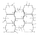
従来のこの種のプレキャストブロックとしては図4に記載のものがある。ここに図示した8個のプレキャストブロックは、さらに具体的にはPCブロックであり、図示のPCブロック1は、補強土壁工法のコンクリートスキンに使用した例の正面図である。各PCブロック1は、正面において四辺形をした本体2と、この本体2の左右の辺の中央部に左右外側に向けて一体に突設された継手部3とからなる。かかるPCブロック1の正面は本体2と継手部3とが同一平面をなしている。
【0003】
そして、上下方向に列をなして並べられた各PCブロック1の左右に、同様に上下方向に列をなして並べられた各PCブロック1が配置されるが、このと左右に隣合うPCブロック1は、上下方向に半分の寸法だけ上下にずれて配置されて、左右の各列のPCブロック1の継手部3が向き合って相互に凹凸係合するようになっている。したがって、継手部3の上下方向の寸法は、本体2の上下方向の寸法の約半分となっている。この約半分の寸法の意味は、各PCブロック1間の目地の寸法を含めるとちょうど半分になる寸法の意味である。
【0004】
このようにして多数のPCブロック1が一面に並べられ且つ目地4が充填されて、コンクリートスキンが形成されている。
【0005】
【発明が解決しようとする課題】
しかしながら、前記従来のPCブロック1の構造は、本体2と継手部3との正面が同一平面をなし且つ平坦であるために、多数のPCブロック1を並べると、各PCブロック1間の目地4が最も目立つものとなる。この目地4は、コンクリートスキン表面に、上下方向には角張って蛇行する連続線になって表れ、且つ水平方向には途切れた水平線になって表れるから、地域住民や付近の通行人に視覚による錯綜感と違和感を与えるという不具合がある。
【0006】
そこで、この発明の目的は、補強土壁工法のコンクリートスキンや、ブロック積擁壁のブロックなどのように、多数並べられて施工されたプレキャストブロックの景観をよくすることにある。
【0007】
【課題を解決するための手段】
この発明は、正面において四辺形をした本体の左右の辺の中央部に左右外方に向けて継手部を一体に突設して正面太十字型をしたプレキャストブロックを複数並べて構成されるプレキャストブロック構造であって、前記継手部の正面に凹凸を形成し、且つ前記複数のプレキャストブロックは、前記継手部が上下方向に列をなして配置されるように、上下左右に並べられてなるものである。
太十字型とは、十字をなして交差する各線の幅を大にした形態を称し、別の見方をすれば、四辺形のうち四隅の部分を小さい四辺形で切欠した形態をいう。
【0008】
これによれば、多数のプレキャストブロックを上下左右に並べて施工したときに、上下のプレキャストブロック間では目地の細い幅での線状の模様しか表れないが、左右のプレキャストブロック間では、継手部の本体からの突設寸法に相当する幅の縦の直線が表れ、この直線には多数の凹凸が形成されるから、この太い直線がよく目につくことになる。すると、縦の目立つ平行な直線と、これら直線の間で縦に連続する本体とによる縦縞模様がコンクリートスキン等の施工面に表れることになって、すっきりした景観となる。
【0009】
また、前記継手部の正面を前記本体の正面よりも低い位置に設定して、並べられた左右のプレキャストブロックの間の、前記の縦の直線をなす継手部が溝をなすように構成すると好適である。
【0010】
このようにすることによって、前記の目立つ縦の直線と、プレキャストブロックの本体との間に凹凸が形成され、この凹凸が上下に連続することになるから、外観における縦の線が強調されて景観がよくなる。
【0011】
さらに、請求項2の発明によれば、前記の縦の直線が溝になって表れるため、この部分が排水溝としての機能を備える。このため、前記の溝を、汚れを伴った水が流下するために、プレキャストブロックの本体が局部的に汚れることが防止される利点もある。
【0012】
【発明の実施の形態】
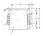
図1には、補強土壁工法のコンクリートスキンに使用するプレキャストブロックの一例としてPCブロック1が示される。このPCブロック1は、正面において四辺形をし且つ全体が均一な厚みをした本体2と、この本体2の左右の辺の中央部に左右外方に向けて一体に突設された継手部3とからなる。
【0013】
本体2の寸法の一例を挙げれば、幅Aが1335mm、高さBが1480mm、厚さCが180mmで正面において若干縦長の四辺形をなしている。また、継手部3の寸法の一例を挙げれば、本体2の左右の辺に沿う方向の長さFが730mm、本体2の左右の辺からの突出幅Dが190mmであって、本体2の高さB方向の中央に配置され、よって、本体2の左右の辺における継手部3より上の寸法Eと同下の寸法Gは夫々375mmである。これらの寸法は前記の通り一例にすぎないものであるから、本発明はこれらの寸法に限定されるべきものでないことは勿論である。
【0014】
前記継手部3は背面において本体2の背面と同一平面をなしているが、継手部3の厚さは本体2の厚さCより小さくなっていて継手部3の正面が本体2の正面よりも低くなっている。その継手部3の正面には凹凸が形成されている。この実施形態における前記凹凸は本体2の左右の辺に沿う方向に山と谷が繰り返し形成されて構成される。
【0015】
而して、PCブロック1は、本体2と継手部3とで、正面から見ると太十字型をなしている。
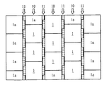
かかるPCブロック1を同一面上の上下左右に多数並べて補強土壁工法のコンクリートスキンを形成した例が図2に示される。ここでは、継手部3の位置が本体2の左右になり、且つ正面が水平方向又は斜め上方向を向いた姿勢で、各PCブロック1が下から上に順次積み上げられる。
【0016】
各PCブロック1は上下方向には列をなし、左右方向には隣合うPCブロック1どうしが高さ寸法の半分づつずれて配置され、その結果、PCブロック1の上下はPCブロック1の本体2どうしが接し、左右は隣接するPCブロック1の継手部3が本体2の側面に接する。また左右に隣接するPCブロック1どうしは、夫々の継手部3が相互に凹凸係合して、各継手部3が上下方向に列をなして配置される。なお、隣接する各PCブロック1間では、本体2どうしの間と、本体2と継手部3との間と、継手部3どうしの間においては20mmの目地を介して接する。
【0017】
なお、図2において符号1aで示すのはPCブロック1の一部の構造を備えたブロックであって、所定の面積のコンクリートスキンの周縁部を構成するために予め成型されたものである。
【0018】
かくして、コンクリートスキンとしては、図2に示すように、PCブロック1の本体2が上下に直線状に連続する幅広部10と、継手部3が上下に直線状に連続する幅狭部11とが形成される。しかも幅狭部11は長手方向に凹凸が無数に繰り返し形成されおり且つ幅広部10よりも凹陥して溝が形成されているため、これが視覚的にアクセントとなって、幅広部10と幅狭部11とは明確に区別されて全体として幅広部10と幅狭部11とが縦縞になって表れる。よって、コンクリートスキンとして、見る者にすっきりした好ましい景観となる。
【0019】
特に、この実施形態では、幅狭部11が幅広部10よりも凹陥しているため、各PCブロック1が水平又は傾斜した面、或いは垂直な面に配置施工される場合でも、この凹陥した幅狭部11が排水溝として機能することになる。すると、ここを、汚れを伴った水がこれに誘導されて流下するために、PCブロック1の本体2の正面が、汚れを伴う雨水等によって局部的に汚れることが防止される利点もある。一方、幅狭部11の表面には無数の凹凸が形成されているため、前記汚れのうち雨水等によって流下せずに前記凹凸の凹部に残留する場合があるが、この残留した汚れによって前記幅狭部11の色あい又は明るさが幅広部10と相違することになると、前記の視覚的なアクセントが強調されて、幅広部10と幅狭部11との区別がさらに明確になって、前記の景観がさらにすぐれたものになる利点がある。
【0020】
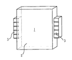
図3はプレキャストブロックの例としての別のPCブロック1の形態であって、継手部3の正面に溝を形成することにより凹凸としている。この溝は所定同一間隔で形成されていて、前記幅狭部11としては、上下方向に多数の溝が同一間隔で表れることになる。他の構成及び作用効果については図1及び図2のものと同一である。
【0021】
以上、図示の実施形態では、継手部3の正面を本体2の正面より低くしているが、この発明としては継手部3の正面を本体2の正面と同一面にしてもよい。また、図示の実施例では本体2の正面に何らの図柄も形成されてないが、適宜の図柄を設けもよい。さらに、図示の実施例のPCブロック1は補強土壁工法のコンクリートスキンに用いるブロックであるが、ブロック積擁壁のブロックに用いるものとすることもできる。この場合には、本体2の背面には四角錐状の突起が一体成型されることは、この種のブロックで周知の通りである。
【0022】
なお、この発明に用いるプレキャストブロックとして、前記の実施形態ではPCブロック1を例示したが、他の材質からなるプレキャストブロックを用いることができるのは勿論である。
【0023】
【発明の効果】
以上説明したように、この発明にあっては、縦に連続する継手部による縦の目立つ平行な直線と、これら直線の間で縦に連続する本体とによる縦縞模様がコンクリートスキン等の施工面に表れることになって、すっきりした景観となる。
【0024】
また、請求項2の発明によれば、さらに、前記の目立つ縦の直線と、プレキャストブロックの本体との間に凹凸が形成され、この凹凸が上下に連続することで溝を形成するから、外観における縦の線が強調されて景観がさらによくなる。さらにまた、前記の縦の直線が溝になって表れるため、この部分が排水溝として機能し、この溝を、汚れを伴った水が誘導されて流下するために、プレキャストブロックの本体の正面が汚れを伴う雨水等によって局部的に汚れることが防止される効果もある。
【図面の簡単な説明】
【図1】プレキャストブロックの一実施形態を示す斜視図。
【図2】図1のプレキャストブロックを用いて施工した補強土壁工法のコンクリートスキンの正面図。
【図3】プレキャストブロックの他の実施形態を示す斜視図。
【図4】従来のPCブロックを用いて施工したコンクリートスキンの正面図。
【符号の説明】
1 プレキャストブロック(PCブロック)
2 本体
3 継手部
10 幅広部
11 幅狭部[0001]
BACKGROUND OF THE INVENTION
The present invention relates to a precast block structure used for a concrete skin of a reinforced earth wall construction method, a block of a block retaining wall, or the like.
[0002]
[Prior art]
A conventional precast block of this type is shown in FIG. The eight precast blocks shown here are more specifically PC blocks, and the shown
[0003]
Similarly, the
[0004]
In this way, a large number of
[0005]
[Problems to be solved by the invention]
However, since the structure of the
[0006]
Therefore, an object of the present invention is to improve the scenery of precast blocks that are arranged side by side, such as a concrete skin of a reinforced earth wall construction method or a block retaining wall block.
[0007]
[Means for Solving the Problems]
The present invention provides a precast block configured by arranging a plurality of precast blocks in a front thick cross shape by integrally projecting joint portions toward the left and right sides at the center of left and right sides of a quadrilateral main body in front. It is a structure, and unevenness is formed in the front of the joint part , and the plurality of precast blocks are arranged vertically and horizontally so that the joint parts are arranged in rows in the vertical direction. is there.
The thick cross shape refers to a form in which the width of each line intersecting in a cross shape is increased, and from another viewpoint, the form in which four corners of the quadrilateral are cut out with a small quadrilateral.
[0008]
According to this, when a large number of precast blocks are arranged side by side vertically, only a linear pattern with a narrow joint width appears between the upper and lower precast blocks, but between the left and right precast blocks, A vertical straight line having a width corresponding to the projecting dimension from the main body appears, and a large number of irregularities are formed on this straight line. Then, the vertical stripe pattern by the vertical conspicuous parallel straight line and the main body vertically continuous between these straight lines appears on the construction surface such as a concrete skin, resulting in a clean landscape.
[0009]
Further, it is preferable that the front surface of the joint portion is set at a position lower than the front surface of the main body so that the joint portion forming the vertical straight line between the left and right precast blocks forms a groove. It is.
[0010]
By doing so, irregularities are formed between the above-mentioned conspicuous vertical straight lines and the main body of the precast block, and these irregularities are continuous up and down, so that the vertical lines in the appearance are emphasized and the landscape Will be better.
[0011]
Furthermore, according to the invention of
[0012]
DETAILED DESCRIPTION OF THE INVENTION
FIG. 1 shows a
[0013]
As an example of the dimensions of the
[0014]
Although the
[0015]
Thus, the
FIG. 2 shows an example in which a large number of
[0016]
Each
[0017]
In FIG. 2,
[0018]
Thus, as shown in FIG. 2, the concrete skin includes a
[0019]
In particular, in this embodiment, since the
[0020]
FIG. 3 shows a form of another
[0021]
As described above, in the illustrated embodiment, the front surface of the
[0022]
As the precast block used in the present invention, the
[0023]
【The invention's effect】
As described above, according to the present invention, vertical stripes formed by vertically connecting parallel straight lines and vertically continuous main bodies between the straight lines are formed on the construction surface of the concrete skin or the like. It will appear and become a clean landscape.
[0024]
Further, according to the invention of
[Brief description of the drawings]
FIG. 1 is a perspective view showing an embodiment of a precast block.
FIG. 2 is a front view of a concrete skin of a reinforced earth wall method constructed using the precast block of FIG.
FIG. 3 is a perspective view showing another embodiment of the precast block.
FIG. 4 is a front view of a concrete skin constructed using a conventional PC block.
[Explanation of symbols]
1 Precast block (PC block)
2
Claims (2)
前記継手部の正面に凹凸を形成し、
且つ前記複数のプレキャストブロックは、前記継手部が上下方向に列をなして配置されるように、上下左右に並べられることを特徴とするプレキャストブロック構造。In the precast block structure constituted by arranging a plurality of precast blocks in the form of a front thick cross by projecting joint portions integrally to the left and right sides of the center part of the left and right sides of the quadrilateral main body in the front,
Forming irregularities on the front of the joint ,
The plurality of precast blocks are arranged vertically and horizontally so that the joint portions are arranged in rows in the vertical direction .
Priority Applications (1)
| Application Number | Priority Date | Filing Date | Title |
|---|---|---|---|
| JP21611098A JP3967006B2 (en) | 1998-07-30 | 1998-07-30 | Precast block structure |
Applications Claiming Priority (1)
| Application Number | Priority Date | Filing Date | Title |
|---|---|---|---|
| JP21611098A JP3967006B2 (en) | 1998-07-30 | 1998-07-30 | Precast block structure |
Publications (2)
| Publication Number | Publication Date |
|---|---|
| JP2000045301A JP2000045301A (en) | 2000-02-15 |
| JP3967006B2 true JP3967006B2 (en) | 2007-08-29 |
Family
ID=16683407
Family Applications (1)
| Application Number | Title | Priority Date | Filing Date |
|---|---|---|---|
| JP21611098A Expired - Fee Related JP3967006B2 (en) | 1998-07-30 | 1998-07-30 | Precast block structure |
Country Status (1)
| Country | Link |
|---|---|
| JP (1) | JP3967006B2 (en) |
-
1998
- 1998-07-30 JP JP21611098A patent/JP3967006B2/en not_active Expired - Fee Related
Also Published As
| Publication number | Publication date |
|---|---|
| JP2000045301A (en) | 2000-02-15 |
Similar Documents
| Publication | Publication Date | Title |
|---|---|---|
| US5503498A (en) | Paving stone with lateral spacers | |
| US5348417A (en) | Compound pavement stone | |
| CA2088013C (en) | Interlocking paving stone for closed and open drainage patterns | |
| US7546717B2 (en) | Timber covering for exteriors and interiors | |
| HK103194A (en) | Angled paving stone | |
| NZ516734A (en) | A trapezoid wall block with upper lips and a lower base as interlocking features stacked vertically for the creation of arcurate, curved and/or sinusoidal retaining walls | |
| US5941657A (en) | Floor covering made up of pentagonal concrete moulded parts with joints between them | |
| SK152796A3 (en) | Concrete paving stone | |
| JP2012107470A (en) | Building plate | |
| US20040168393A1 (en) | System of stackable blocks as well as block and a joining element of the system | |
| JP3967006B2 (en) | Precast block structure | |
| JP3995177B2 (en) | Inorganic molded body and stacking method thereof | |
| JP3793761B2 (en) | Building boards and structures | |
| JP5226991B2 (en) | Exterior wall structure | |
| JP3980223B2 (en) | Architectural board | |
| JPH0893111A (en) | Flat roof structure | |
| JPH0643005U (en) | Paving stone tiles | |
| JP3347227B2 (en) | Paving stones with spacers on the side | |
| KR200363388Y1 (en) | concrete block structure for revetment | |
| JPS6042095Y2 (en) | Covering concrete block | |
| JP2702795B2 (en) | Ceiling material mounting structure | |
| KR200320477Y1 (en) | Functional block of sidewalk | |
| JPH0823205B2 (en) | Building board | |
| PT688921E (en) | APPROVED MODULE FOR PAVING FORMATION | |
| JPS6223876Y2 (en) |
Legal Events
| Date | Code | Title | Description |
|---|---|---|---|
| A621 | Written request for application examination |
Free format text: JAPANESE INTERMEDIATE CODE: A621 Effective date: 20050510 |
|
| A977 | Report on retrieval |
Free format text: JAPANESE INTERMEDIATE CODE: A971007 Effective date: 20070215 |
|
| A131 | Notification of reasons for refusal |
Free format text: JAPANESE INTERMEDIATE CODE: A131 Effective date: 20070306 |
|
| A521 | Written amendment |
Free format text: JAPANESE INTERMEDIATE CODE: A523 Effective date: 20070328 |
|
| TRDD | Decision of grant or rejection written | ||
| A01 | Written decision to grant a patent or to grant a registration (utility model) |
Free format text: JAPANESE INTERMEDIATE CODE: A01 Effective date: 20070515 |
|
| A61 | First payment of annual fees (during grant procedure) |
Free format text: JAPANESE INTERMEDIATE CODE: A61 Effective date: 20070530 |
|
| R150 | Certificate of patent or registration of utility model |
Free format text: JAPANESE INTERMEDIATE CODE: R150 |
|
| LAPS | Cancellation because of no payment of annual fees |