JP3966697B2 - refrigerator - Google Patents
refrigerator Download PDFInfo
- Publication number
- JP3966697B2 JP3966697B2 JP2001100150A JP2001100150A JP3966697B2 JP 3966697 B2 JP3966697 B2 JP 3966697B2 JP 2001100150 A JP2001100150 A JP 2001100150A JP 2001100150 A JP2001100150 A JP 2001100150A JP 3966697 B2 JP3966697 B2 JP 3966697B2
- Authority
- JP
- Japan
- Prior art keywords
- evaporator
- refrigerator
- temperature
- compartment
- room
- Prior art date
- Legal status (The legal status is an assumption and is not a legal conclusion. Google has not performed a legal analysis and makes no representation as to the accuracy of the status listed.)
- Expired - Lifetime
Links
Images


Landscapes
- Devices That Are Associated With Refrigeration Equipment (AREA)
Description
【0001】
【発明の属する技術分野】
本発明は、冷蔵室用蒸発器と冷凍室用蒸発器を備え、切替弁を用いて冷蔵室又は冷凍室側に冷媒を循環させる冷凍サイクルをもち、冷蔵室、冷凍室冷却を切り替えることで交互に冷却する冷蔵庫に関する。
【0002】
【従来の技術】
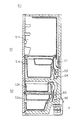
最年の家庭用冷蔵庫では、その大型化に伴い省電力設計とされており、その中で冷蔵室用蒸発器、冷凍室用蒸発器を有する構成が考えられている。ここで図面に基づいて上記構成の冷蔵庫を説明する。図7は従来冷蔵庫を示す概略断面図である。図8は従来冷蔵庫の冷却運転移行条件を示すフローチャートである。図9は従来冷蔵庫の通常運転時における冷蔵室用蒸発器温度を示したものである。冷蔵庫本体50は冷蔵貯蔵室51a、野菜室51bを有する冷蔵室51と、製氷室(図示せず)、切替室52a、冷凍貯蔵室52bを有する冷凍室52を備えている。冷蔵室51、冷凍室52の庫内奥側にそれぞれ冷蔵室用蒸発器53と冷凍室用蒸発器55が配置され、冷蔵室用蒸発器53により冷蔵室51を冷却し、冷凍室用冷却器55により冷凍室52を冷却している。そしてこの冷蔵庫50の場合、冷媒を冷凍室用蒸発器55に流す第1冷却運転と、冷媒を冷蔵室用蒸発器53に流す第2冷却運転とを切り替える切替弁(図示せず)を備えている。
【0003】
この第1冷却運転から第2冷却運転に移行するには図8に示すように、第1冷却運転中、冷凍室52の室内温度を検知する冷凍室温度センサ(図示せず)が冷却停止温度(庫内温度が低くなり冷却が不要な温度、例えば−22℃)より低くなったときS11、又は運転積算時間がT1(例えば30分)を経過しS12、冷蔵室51が冷却開始温度(庫内温度が高くなり冷却が必要な温度例えば4℃)になったS13ときに切替弁が切替動作をして第2冷却運転に移行するS17。また冷蔵室51の室内温度を検知する冷蔵室温度センサ(図示せず)が冷却停止温度(庫内温度が低くなり冷却が不要な温度、例えば1℃)より低くなったときS14、又は運転積算時間がT2(例えば20分)を経過しS15、冷凍室52が冷却開始温度(庫内温度が高くなり冷却が必要な温度−18℃)になったS16ときに切替弁が切替動作をして第1冷却運転に移行するS17。このようにして第1冷却運転と第2冷却運転を交互に実行することにより、冷凍室52と冷蔵室51を交互に冷却している。上記構成によれば、各蒸発器の蒸発温度を比較的高く設定することが可能となるため、冷凍サイクルの効率を高くすることができ、ひいては省電力運転となる。
【0004】
さて、上記構成の冷蔵庫50において、冷凍室用蒸発器55に付着した霜を除霜するには、第1冷却運転積算時間がT3(例えば、6時間)を経過した場合に冷凍室用蒸発器50に着霜していると判断し、次に第2冷却運転に移行したときに、冷凍室用蒸発器50を加熱する冷凍室除霜ヒータ(以下、F除霜ヒータ56とする)に通電を開始する。そして、冷凍室用蒸発器50の温度を検知する冷凍室用蒸発器温度センサ(図示せず)が除霜終了温度(例えば0℃)まで上昇したことを検知した時点でF除霜ヒータ56を断電する。また冷蔵室用蒸発器53に付着した霜を除霜するには、第2冷却運転積算時間がT4(例えば、8時間)を経過し、次に第1冷却運転に移行したときに、冷蔵室用蒸発器53を加熱する冷蔵室除霜ヒータ54(以下、R除霜ヒータ)に通電を開始する。そして、冷蔵室用蒸発器53の温度を検知する冷蔵室用蒸発器温度センサ(図示せず)が除霜終了温度(例えば0℃)まで上昇したことを検知した時点でR除霜ヒータ54を断電する。
【0005】
また図9に示すように、冷蔵室用蒸発器53の除霜には第1冷却運転中に、冷蔵室用冷機循環ファンを構成する冷蔵室用ファン57を継続して運転させることにより、冷蔵室用蒸発器53の着霜を軽減させる毎サイクル除霜が行われているが、冷蔵室用蒸発器温度を計測してみると、0℃まで上昇するが、第1冷却運転が終了して、第2冷却運転が開始されると、再び温度は下がるため0℃以上にはならず、付着した霜が完全に融解しない。このため冷蔵室用ファン57の運転だけでは十分に除霜されず、T4ごとにR除霜ヒータ54の通電は必要不可欠であった。
【0006】
【発明が解決しようとする課題】
しかしながら上記構成の冷蔵庫のような除霜ヒータ54の通電は非常に電力を消費するばかりか、通電時には圧縮機58を停止させるので、圧縮機58起動には過剰な電力を消費するため運転効率の悪いものであった。また除霜ヒータ54の通電と圧縮機58の停止(冷却運転の停止)により庫内温度は急激に上昇し、運転を再開しても、庫内の設定温度に達するにはかなりの時間がかかってしまうため、食品の腐食を進行させてしまうものであった。さらに冷媒に可燃性冷媒を用いて冷媒漏れが生じた際には、除霜ヒータの通電が爆発源となる可能性があり、安全性に優れていないものであった。
【0007】
そこで本発明は上記問題を鑑み、R除霜ヒータを廃止し、確実に冷蔵室用蒸発器の除霜が行われ、かつ冷却運転効率を向上させる冷蔵庫を提供することにある。
【0008】
【課題を解決するための手段】
請求項1の発明によれば、圧縮機と、凝縮器と、冷蔵室用蒸発器と、冷凍室用蒸発器と、冷媒の流れを前記冷凍室用蒸発器と前記冷蔵室用蒸発器とに切り替える切替弁とを有する冷凍サイクルと、前記冷蔵室用蒸発器と冷蔵室内の空気を熱交換する冷蔵室用ファンと、前記冷蔵室用蒸発器の温度を検知する冷蔵室用蒸発器温度センサと、冷蔵室の庫内温度を検出する冷蔵室温度センサと、前記切替弁を切り替え、冷媒の流れを前記冷凍室用蒸発器から前記冷蔵室用蒸発器に移行させる手段とを備え、前記移行させる手段は、前記冷蔵室用蒸発器温度センサの検出温度が冷蔵室用蒸発器除霜終了温度以上にならなければ冷媒の流れを前記冷凍室用蒸発器から前記冷蔵室用蒸発器に移行させないとともに、前記冷蔵室用蒸発器除霜終了温度は、通常よりも長い特定周期ごとに高くシフトするところに特徴を有するものである。
【0009】
上記構成によれば、冷媒の流れが冷凍室用蒸発器から冷蔵用蒸発器に移行するとき、即ち第1冷却運転から第2冷却運転に移行するときに、冷蔵室用蒸発器温度センサの検出温度が冷蔵室用蒸発器除霜終了温度以上にならなければ移行しないため、第1冷却運転中に、冷蔵室用蒸発器に付着した霜が除霜されるまで、第2冷却運転に移行しない。よって、冷蔵室用除霜ヒータを廃止することができ、もって部品点数削減による組立作業の簡略化、ならびにコスト削減を図ることができる。また除霜による圧縮機停止、ならびにヒータ通電が全くなくなるため運転効率の向上、省エネルギー化、さらには庫内温度上昇による食品の腐食進行を防ぐことができる。
【0012】
また、上記構成において、通常より長い特定周期(例えば第2冷却運転の積算時間が6時間)ごとに、第1冷却運転から第2冷却運転への移行の際に、冷蔵用蒸発器除霜終了温度を高くシフトするため、より完全に除霜されるとともに、通常よりも長い特定周期毎であるため、第2冷却運転の冷却効率の向上を図ることができる。
【0013】
請求項2の発明によれば、通常よりも長い特定周期毎に、前記冷蔵室用ファンの停止温度を高くシフトする構成である。この構成によれば、第1冷却運転中に冷蔵室用蒸発器の着霜を融解するため冷蔵室用ファンを駆動しているが、冷蔵用ファンの停止温度を高くシフト(例えば、+2K)したにより、冷蔵室用蒸発器の除霜を確実に補うことができる。また特定周期毎であるため、過剰に冷蔵室用ファンの運転をすることがなく、もって省エネルギー化を図ることができる。
【0014】
請求項3の発明によれば、冷媒は可燃性冷媒であることを特徴とする構成である。この構成によれば可燃性冷媒漏れ時に、危険性の高い冷蔵室除霜ヒータを廃止しているため、安全性が高くなり、もって可燃性冷媒を使用しても信頼性の高い冷蔵庫が得られることができる。
【0015】
【発明の実施の形態】
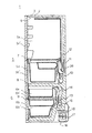
以下、本発明の一実施例について、図面に基づいて説明する。図3は、本実施例の冷蔵庫の概略的な断面図である。この図3に示すように、冷蔵庫本体1は鉄板製の外箱2と、プラスチック製の内箱3と、これらの間に発泡充填された例えばウレタンフォームからなる断熱材4とから構成されている、断熱箱体である。この冷蔵庫本体1内には、冷蔵室5、冷凍室6が設けられており、冷蔵室5内には、冷蔵貯蔵室5a、野菜室5b、冷凍室6内には切替室6a、冷凍貯蔵室6bが上から順に設けられている。なお、切替室の隣には、製氷室(図示せず)が横に並ぶように配設されている。
【0016】
また、冷蔵貯蔵室5aの前面には、ヒンジ開閉式の断熱性の扉5a´が設けられている。野菜室5b、切替室6a、冷蔵貯蔵室6b、のそれぞれの前面には、引出し式の断熱性の扉5b´、6a´、6b´が設けられている。そして、冷蔵貯蔵室5a、野菜室5bとの間は、プラスチック製の仕切り板7により仕切られ、野菜室5bと切替室6a及び製氷室との間は断熱仕切壁8により仕切られ、切替室6a及び製氷室6bとの間は断熱仕切壁9により仕切られている。
【0017】
更に、野菜室5bの背部には冷蔵室用蒸発器10、冷蔵室用冷気循環ファンを構成する冷蔵室用ファン11などが配置されている。この冷蔵室用ファンが駆動されると、冷蔵室用蒸発器10により冷却された冷気は、送風ダクト12を介して冷蔵貯蔵室5a室内に供給された後、野菜室5bを経て循環されることにより、冷蔵貯蔵室5a及び野菜室5bが冷却される構成となっている。
【0018】
また、冷凍室6の背部には上から順に冷凍室用冷気循環ファンを構成する冷凍室用ファン14、冷凍室用蒸発器13、及び、冷凍室用蒸発器13を加熱するF除霜ヒータ15などが配設されている。この場合、冷凍室用ファン14が駆動されると、冷凍室用蒸発器13により冷却された冷気は、製氷室及び冷凍貯蔵室6b内に供給、循環されることにより、製氷室及び冷凍貯蔵室6bが冷却される構成となっている。
【0019】
なお、切替室6aの内部温度は、扉前面に設けられた操作スイッチ(図示せず)により複数段階に切替設定できるように構成されている。具体的には、切替室6a背部に冷気の吹出し口の開度を設定温度に応じて自動調節するダンパ装置38(図6参照)が設けられている。これにより、切替室6aは冷蔵貯蔵室(室温が約2℃)、野菜室(室温が約3℃)、チルド室(室温が約0℃)、パーシャル室(室温が約−3℃)、冷凍貯蔵室(室温が約−18℃)、ワイン室(室温が約8℃)のいずれかとして選択的に使用できるように構成されている。
【0020】
一方、冷蔵庫本体1底部には、機械室16が形成されている。この機械室16内には、圧縮機17、除霜水を受けて蒸発させる蒸発皿18、ワイヤコンデンサからなる凝縮器20、圧縮機17及び凝縮器20を冷却する放熱用ファンを構成する機械室用ファン19などが配設されている。
【0021】
また、図4は、本実施例の冷蔵庫の冷凍サイクル21を示す図である。この図4のに示すように、冷凍サイクル21は圧縮機17、凝縮器20、切替手段を構成する切替弁22、Rキャピラリチューブ23、冷蔵室用蒸発器10、Fキャピラリチューブ24、冷凍室用蒸発器13、アキュームレータ26を順次接続されている。この場合、冷蔵室用蒸発器10と冷凍室用蒸発器13との間は、連結パイプ25を介して接続されている。
【0022】
上記構成の場合、切替弁22は、凝縮器20から連結パイプ25を介してFキャピラリチューブ24及び冷凍室用蒸発器13のみに冷媒を供給する第1冷却運転と、凝縮器20からRキャピラリチューブ23を介して冷蔵室用蒸発器10、冷凍室用蒸発器13順に冷媒を供給する第2冷却運転とに切り替える機能を有している。また上記冷媒は、可燃性冷媒(例えば、HC冷媒)を使用している。
【0023】
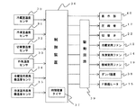
一方、図6は、本実施例の冷蔵庫1の電気的構成を示す図である。この図6に示すように、制御装置36は、マイクロコンピュータを主体に構成されており、冷蔵庫1の運転全般を制御する機能を有している。この制御装置36は、冷蔵貯蔵室5a内の温度を検出する冷蔵室温度センサ30、冷凍貯蔵室6b内の温度を検出する冷凍室温度センサ31、切替室6a内の温度を検出する切替室温度センサ32、庫外の温度を検出する外気温度センサ33、冷蔵室用蒸発器10の温度を検出する冷蔵室用蒸発器温度センサ34、冷凍室用蒸発器13の温度を検出する冷凍室温度センサ35からの各温度検出信号を受け入れるように構成されている。
【0024】
そして、制御装置36は、表示部37、圧縮機17、切替弁22、冷蔵室用ファン12、冷凍室用ファン14、機械室用ファン19、ダンパ装置38、F除霜ヒータ15とを駆動回路39を介して駆動するように構成されている。このうち、圧縮機17、冷蔵室用ファン12、冷凍室用ファン14、機械室用ファン19は駆動回路39に内蔵されたインバータ回路によりそれぞれ可変速駆動されるように構成されている。
【0025】
さて、上記した冷蔵庫において、冷蔵室5を冷却する冷蔵冷却運転(即ち、第2冷却運転)を実行する場合には、制御装置36は、切替弁22を上記した第2冷却運転に切り替えると共に、冷蔵室用ファン12、機械室用ファン19を駆動させる。これにより、圧縮機17で圧縮された高温高圧のガス化された冷媒は凝縮器20に送られ、ここで放熱して液化しながら切替弁22、Rキャピラリチューブ23を介して冷蔵室用蒸発器10に送られる。そして、液冷媒は、冷蔵室用蒸発器10内で蒸発し、その際に周囲の熱を奪う。これに伴い、冷凍室用蒸発器10の周囲の空気が冷却され、この冷却された冷気が、冷蔵室用ファン12の送風作用により冷蔵室5に供給され、各室を冷却する。また冷蔵室用ファン12は、第1冷却運転中にも駆動し、冷蔵室用蒸発器10に付着した霜の除霜を促進し、この除霜により霜は気化もしくは液化し、この冷気を冷蔵室5内に循環するため冷蔵室5の湿度が向上される。
【0026】
一方、冷凍室6を冷却する冷凍冷却運転(即ち、第1冷却運転)を実行する場合には、制御装置36は、切替弁22を上記した第1冷却運転に切り替えると共に、冷凍室用ファン14及び機械室用ファン19を駆動させる。これにより、圧縮機17で圧縮され高温高圧のガス化された冷媒は凝縮器20に送られ、ここで放熱して液化しながら切替弁22、連結パイプ25、Fキャピラリチューブ24を介して冷凍室用蒸発器13に送られる。そして、液冷媒は冷凍室用蒸発器13内で蒸発し、冷凍室用蒸発器13の周囲の空気が冷却され、この冷却された冷気が冷凍室用ファン14の送風作用により冷凍室6に供給され、各室を冷却する。なお切替室6aは、設定された温度となるようにダンパ装置38によって冷気の供給量が調節されるように構成されている。
【0027】
このように第1冷却運転と第2冷却運転とを交互に実行することにより、各室が冷却されるように構成されている。この構成の場合、冷蔵室用蒸発器10、冷凍蒸発器13の蒸発温度を、比較的高い蒸発温度に設定して運転することが可能であるため、冷凍サイクル21の効率を向上させることができ、ひいては節電することができる。
【0028】
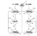
次に、上記構成の冷蔵庫において、第2冷却運転から第1冷却運転に移行する場合について、図1に基づいて説明する。第2冷却運転が開始S7されると、制御装置36に内蔵されている時間積算タイマ37がカウントされる。このカウントは現第2冷却運転の積算時間をカウントするカウント1と第2冷却運転毎ごとの積算時間を継続してカウントするカウント2がある。そのまま冷蔵室5は冷却されると、冷蔵室温度センサ30の検出温度は、予め設定されている庫内の設定温度(例えば、2℃)より下降し、冷却停止温度(設定温度−1K、例えば1℃)に達すると冷却は不要と判断するS8。また、冷却停止温度に達していなくても、上記カウント1積算時間がt2(例えば、20分)より長くなりS9、冷却運転を行っていない冷凍室6側において、冷凍室温度センサ31が冷却開始温度(設定温度+2K、例えば−18℃)より高い温度を検出するとS11、第1冷却運転が必要と判断するため、切替弁22を動作させS1、第2冷却運転に切替わる。この積算時間による判定は、庫内温度判定により精度が充実されていれば、なくてもよい。
【0029】
一方、第1冷却運転から第2冷却運転に移行する場合については、第1冷却運転が開始S2されると、時間積算タイマ37がカウントされる。このカウントは現第1冷却運転の積算時間をカウントするカウント3と第1冷却運転毎ごとの積算時間を継続してカウントするカウント4がある。そのまま冷凍室6は冷却されると、冷凍室温度センサ31の検出温度は、予め設定されている庫内の設定温度(例えば、−20℃)より下降し、冷却停止温度(設定温度−2K、例えば−22℃)に達すると冷却は不要と判断するS3。また、冷却停止温度に達していなくても、上記カウント3積算時間がt1(例えば、30分)より長くなりS4、冷却運転を行っていない冷蔵室5側において、冷蔵室温度センサ30が冷却開始温度(設定温度+1K、例えば3℃)より高い温度を検出するとS5、第1冷却運転が必要と判断するため、第1冷却運転から第2冷却運転に移行してもよいと判断する。ここで、冷蔵室用蒸発器10に霜が付着しているか否かの判断するため、冷蔵室用蒸発器温度センサ34の検出温度が3℃(冷蔵室用蒸発器除霜終了温度)より高くなればS6、完全に霜は融解されているため(実験値)切替弁S1が切替動作を行い、第1冷却運転から第2冷却運転に移行する。また、この積算時間による判定は、庫内温度判定により精度が充実されていれば、なくてもよい。
【0030】
次に、冷凍室用蒸発器13に付着した霜を除霜する除霜運転について説明する。除霜は、F除霜ヒータ15に通電し、冷凍室用蒸発器13が加熱されることによって行われる。具体的には、第1冷却運転中に前記カウント4積算時間が所定時間(例えば、6時間)に達すると、設定温度を下げて通常時より庫内温度を低くし、第2冷却運転に移行した後に、F除霜ヒータ15に通電し、冷凍室用蒸発器13を加熱する。そして、冷凍室用蒸発器温度センサ35の検出温度が上昇し、除霜終了温度(例えば、0℃)まで達した時点で、F除霜ヒータ15を断電するように構成されている。このときにはカウント4はリセットされている。
【0031】
一方、冷蔵室用蒸発器10の除霜については、上記のように、第1冷却運転から第2冷却運転に移行するまでに、冷蔵室用蒸発器10は3℃まで上昇しているため、ヒータ通電をすることなく、自然除霜がされる。3℃で冷蔵室用蒸発器10に付着した霜の有無の判定を行っているのは、実験結果に基づくものであって、例えば1℃で霜の有無を判定してしまうと、完全に除霜されているかが不正確であり、また第2冷却運転に移行してしまうと、直ちに霜が付着してしまう。また2℃にしてもセンサの精度により誤差が生じると1℃と同様の結果となるため、3℃で判定することは、庫内温度、及び冷蔵室蒸発器10温度の過剰な上昇を防ぎ、最も正確な判定を行うためである。
【0032】
このような構成の本実施例によれば、図2に示すように第1冷却運転から第2冷却運転に移行するときに、冷蔵室用蒸発器温度センサ34の検出温度が冷蔵室用蒸発器除霜終了温度以上にならなければ、すなわち、第1冷却運転中に冷蔵室用蒸発器10に付着した霜が除霜されるまで、第2冷却運転に移行しない。
よって第1冷却運転中に冷蔵室用蒸発器10の霜が完全に除霜されているため、R除霜ヒータを廃止することができ、もって部品点数削減による組立作業の簡略化、ならびにコスト削減を図ることができる。また除霜による圧縮機停止、ならびにヒータ通電が全くなくなるため運転効率の向上、省エネルギー化、さらには庫内温度上昇による食品の腐食進行を防ぐことができる。
【0033】
また記冷蔵室蒸発器10に付着した霜の有無を判断する冷蔵室用蒸発器温度センサ34検知温度が3℃以上であるため、冷蔵室用蒸発器10は完全に除霜される(実験データより)。よって冷蔵室用蒸発器温度センサ34の検知精度に狂い(略±1K)が生じても十分に除霜することができ、もって品質の向上を図ることができる。また最小限に庫内温度、冷蔵用蒸発器10の温度上昇を防ぐことができ、さらに運転効率の向上、省エネルギー化とすることができる。
【0034】
冷媒に可燃性冷媒を使用しても、可燃性冷媒漏れ時において、爆発の原因となる可能性が高いR除霜ヒータを廃止しているため、安全性が高くなり、もって可燃性冷媒を使用しても信頼性の高い冷蔵庫が得られることができる。
【0035】
また、上記構成の冷蔵庫のように、第1冷却運転を行なう度でなく、通常よりも長い特定周期(例えば第2冷却運転のカウント4積算時間が8時間)ごとに第1冷却運転から第2冷却運転への移行の際に、冷蔵室5の冷却開始温度(例えば、+2K)又は冷蔵室用蒸発器10除霜終了温度を高く(例えば、2K)シフトすれば、通常よりも長い特定周期毎であるため、庫内温度及び第2冷却運転の冷却効率の向上を図ることができ、かつ確実に除霜を行うことができる。
【0036】
さらに、第1冷却運転を行なう度に、冷蔵室用蒸発器10の着霜を融解するため冷蔵室用ファンは駆動しているが、図2に示すように、その停止温度(通常1℃)を高くシフト(例えば、3℃)したことにより、冷蔵室用蒸発器10の除霜を確実に補うことができる。また、通常よりも長い特定周期毎であるため、過剰に冷蔵室用ファン12の運転をすることがなく、もって省エネルギー化を図ることができる。
【0037】
本実施例では冷凍サイクル21の構成で説明をしたが、図5に示すように、冷蔵室用蒸発器10と冷凍室用蒸発器13とを並列に接続し、冷凍室用蒸発器13の圧縮機17入口側に逆止弁41を設けた構成であっても、第1冷却運転、第2冷却運転になんら変わりはないため、上記構成の冷凍サイクル21´であっても本発明の効果を有する。
【0038】
また設定温度及び設定時間などは、冷蔵庫の容積、及び断熱性能によって最適値は変化するためこの限りでなく、設定温度を調節(例えば、強、中、弱等)した場合には、冷却開始温度、冷却停止温度が変化することはいうまでもない。さらに冷蔵庫の性能によっては、上記冷蔵室蒸発器温度センサ34による判定は、第1冷却運転ごとでなく、特定周期で行ってもよい。
【0039】
【発明の効果】
第1冷却運転から第2冷却運転に移行するときに、冷蔵室用蒸発器温度センサの検出温度が冷蔵室用蒸発器除霜終了温度以上にならなければ移行せず、第1冷却運転中に、冷蔵室用蒸発器に付着した霜が除霜されるまで、第2冷却運転に移行しないため、冷蔵室用除霜ヒータを廃止することができ、もって部品点数削減による組立作業の簡略化、ならびにコスト削減を図ることができる。
【図面の簡単な説明】
【図1】本発明の実施形態を示すフローチャートである。
【図2】本発明の実施形態を示すグラフである。
【図3】本発明の実施形態を示す冷蔵庫断面図である。
【図4】本発明の実施形態を示す冷凍サイクルの説明図である。
【図5】本発明の実施形態を示す冷凍サイクルの説明図である。
【図6】本発明の冷蔵庫制御のブロック図である。
【図7】従来の冷蔵庫を示す断面図である。
【図8】従来の冷蔵庫冷却運転を示すフローチャートである。
【図9】従来の冷蔵庫冷却運転のグラフである。
【符号の説明】
1…冷蔵庫、5…冷蔵室、6…冷凍室、10…冷蔵室用蒸発器、11…冷蔵室用ファン、13…冷凍室用蒸発器、15…F除霜ヒータ、16…機械室、17…圧縮機、20…凝縮器、21…冷凍サイクル、22…切替弁、30…冷蔵室温度センサ、31…冷凍室温度センサ、34…冷蔵室用蒸発器温度センサ、37…時間積算タイマ[0001]
BACKGROUND OF THE INVENTION
The present invention includes an evaporator for a refrigerator compartment and an evaporator for a freezer compartment, has a refrigeration cycle in which a refrigerant is circulated to the refrigerator compartment or freezer compartment side using a switching valve, and switches between the refrigerator compartment and freezer compartment cooling alternately. It relates to a refrigerator to be cooled.
[0002]
[Prior art]
The oldest household refrigerator is designed to save power as its size increases, and a configuration having an evaporator for a refrigerator compartment and an evaporator for a freezer compartment is considered. Here, the refrigerator having the above configuration will be described with reference to the drawings. FIG. 7 is a schematic sectional view showing a conventional refrigerator. FIG. 8 is a flowchart showing the cooling operation transition condition of the conventional refrigerator. FIG. 9 shows the evaporator temperature for the refrigerator compartment during normal operation of the conventional refrigerator. The refrigerator
[0003]
In order to shift from the first cooling operation to the second cooling operation, as shown in FIG. 8, during the first cooling operation, a freezer compartment temperature sensor (not shown) for detecting the indoor temperature of the
[0004]
In the
[0005]
Further, as shown in FIG. 9, the defrosting of the
[0006]
[Problems to be solved by the invention]
However, energization of the
[0007]
Therefore, in view of the above problems, the present invention provides a refrigerator that eliminates the R defrost heater, reliably defrosts the evaporator for the refrigerator compartment, and improves the cooling operation efficiency.
[0008]
[Means for Solving the Problems]
According to the invention of
[0009]
According to the above configuration, when the refrigerant flow shifts from the freezer evaporator to the refrigerating evaporator, that is, when the first cooling operation shifts to the second cooling operation, the detection of the refrigerating room evaporator temperature sensor. Since the transition is not made unless the temperature is equal to or higher than the chiller evaporator defrosting end temperature , the second cooling operation is not shifted until the frost attached to the refrigerator refrigerator is defrosted during the first cooling operation. . Therefore, it is possible to eliminate the defrosting heater chillers, it can be achieved with simplified assembly work by reducing the number of components and, as well as cost savings. In addition, since the compressor stop due to defrosting and heater energization are completely eliminated, it is possible to improve operating efficiency, save energy, and prevent the progress of food corrosion due to an increase in the internal temperature.
[0012]
In the above configuration, the refrigeration evaporator defrosting is completed at the transition from the first cooling operation to the second cooling operation every specific period longer than usual (for example, the integrated time of the second cooling operation is 6 hours). to increase the temperature shifted, together with a more complete defrosting, since a long specific cycle every than normal, it is possible to improve the cooling efficiency of the second cooling operation.
[0013]
According to invention of
[0014]
According to the invention of
[0015]
DETAILED DESCRIPTION OF THE INVENTION
Hereinafter, an embodiment of the present invention will be described with reference to the drawings. FIG. 3 is a schematic cross-sectional view of the refrigerator according to the present embodiment. As shown in FIG. 3, the refrigerator
[0016]
Further, a hinged open / close heat-insulating
[0017]
Furthermore, the
[0018]
In addition, on the back of the
[0019]
The internal temperature of the switching
[0020]
On the other hand, a
[0021]
Moreover, FIG. 4 is a figure which shows the refrigerating
[0022]
In the case of the above configuration, the switching
[0023]
On the other hand, FIG. 6 is a figure which shows the electrical constitution of the
[0024]
The
[0025]
In the above-described refrigerator, when the refrigeration cooling operation for cooling the refrigeration chamber 5 (that is, the second cooling operation) is executed, the
[0026]
On the other hand, when performing the freezing cooling operation (namely, 1st cooling operation) which cools the
[0027]
Thus, each chamber is cooled by alternately executing the first cooling operation and the second cooling operation. In the case of this configuration, the evaporating temperature of the
[0028]
Next, in the refrigerator having the above configuration, a case where the second cooling operation is shifted to the first cooling operation will be described with reference to FIG. When the second cooling operation is started S7, the
[0029]
On the other hand, in the case of shifting from the first cooling operation to the second cooling operation, the
[0030]
Next, the defrost operation which defrosts the frost adhering to the
[0031]
On the other hand, for the defrosting of the
[0032]
According to the present embodiment having such a configuration, the temperature detected by the
Therefore, since the frost in the
[0033]
Further, since the temperature detected by the
[0034]
Even if a flammable refrigerant is used as a refrigerant, the safety of the R defrost heater, which has a high possibility of causing an explosion in the event of a flammable refrigerant leak, has been abolished. Even with this, a highly reliable refrigerator can be obtained.
[0035]
In addition, as in the refrigerator having the above-described configuration, the first cooling operation is not performed every time the first cooling operation is performed , but at a specific period longer than usual (for example, the
[0036]
Further, each time the first cooling operation is performed, the refrigeration room fan is driven to melt the frost formation of the
[0037]
In the present embodiment, the configuration of the
[0038]
The set temperature and set time are not limited because the optimum value varies depending on the volume of the refrigerator and the heat insulation performance. When the set temperature is adjusted (for example, strong, medium, weak, etc.), the cooling start temperature Needless to say, the cooling stop temperature changes. Furthermore, depending on the performance of the refrigerator, the determination by the refrigerating room
[0039]
【The invention's effect】
When transitioning from a first cooling operation to the second cooling operation, the detected temperature of the refrigerating compartment evaporator temperature sensor does not migrate if not exceed refrigerator compartment evaporator defrosting completion temperature, during a first cooling operation , Until the frost attached to the evaporator for the refrigerator compartment is defrosted, the second cooling operation is not performed, so the heater for the refrigerator compartment can be abolished, thereby simplifying the assembly work by reducing the number of parts, In addition, cost reduction can be achieved.
[Brief description of the drawings]
FIG. 1 is a flowchart showing an embodiment of the present invention.
FIG. 2 is a graph showing an embodiment of the present invention.
FIG. 3 is a cross-sectional view of a refrigerator showing an embodiment of the present invention.
FIG. 4 is an explanatory diagram of a refrigeration cycle showing an embodiment of the present invention.
FIG. 5 is an explanatory diagram of a refrigeration cycle showing an embodiment of the present invention.
FIG. 6 is a block diagram of refrigerator control according to the present invention.
FIG. 7 is a cross-sectional view showing a conventional refrigerator.
FIG. 8 is a flowchart showing a conventional refrigerator cooling operation.
FIG. 9 is a graph of a conventional refrigerator cooling operation.
[Explanation of symbols]
DESCRIPTION OF
Claims (3)
前記移行させる手段は、前記冷蔵室用蒸発器温度センサの検出温度が冷蔵室用蒸発器除霜終了温度以上にならなければ冷媒の流れを前記冷凍室用蒸発器から前記冷蔵室用蒸発器に移行させないとともに、
前記冷蔵室用蒸発器除霜終了温度は、通常よりも長い特定周期ごとに高くシフトすることを特徴とする冷蔵庫。 A refrigeration cycle having a compressor, a condenser, an evaporator for a refrigerator compartment, an evaporator for a freezer compartment, and a switching valve for switching a refrigerant flow to the evaporator for the refrigerator compartment and the evaporator for the refrigerator compartment; , A refrigerator for the cold room for exchanging heat between the refrigerator for the cold room and the air in the cold room, an evaporator temperature sensor for detecting the temperature of the evaporator for the cold room, and an internal temperature of the refrigerator A refrigerating room temperature sensor, and a means for switching the switching valve and transferring the flow of the refrigerant from the freezing room evaporator to the refrigerating room evaporator,
The means for transferring is configured such that the flow of the refrigerant is transferred from the freezer compartment evaporator to the refrigerating compartment evaporator unless the temperature detected by the refrigerating compartment evaporator temperature sensor becomes equal to or higher than the refrigerating compartment evaporator defrosting end temperature. While not migrating,
The refrigerator defrosting ending temperature for the refrigerator compartment is shifted higher every specific period longer than usual.
前記移行させる手段は、前記冷蔵室用蒸発器温度センサの検出温度が冷蔵室用蒸発器除霜終了温度以上にならなければ冷媒の流れを前記冷凍室用蒸発器から前記冷蔵室用蒸発器に移行させないとともに、
前記冷蔵室用ファンは、前記冷凍用蒸発器に冷媒を流しているときに停止温度に達するまで駆動させ、前記停止温度は通常よりも長い特定周期ごとに高くシフトすることを特徴とする冷蔵庫。 A refrigeration cycle having a compressor, a condenser, an evaporator for a refrigerator compartment, an evaporator for a freezer compartment, and a switching valve for switching a refrigerant flow to the evaporator for the refrigerator compartment and the evaporator for the refrigerator compartment; , A refrigerator for the cold room for exchanging heat between the refrigerator for the cold room and the air in the cold room, an evaporator temperature sensor for detecting the temperature of the evaporator for the cold room, and an internal temperature of the refrigerator A refrigerating room temperature sensor, and means for switching the switching valve and transferring the flow of the refrigerant from the freezing room evaporator to the refrigerating room evaporator,
The means for transferring is configured such that the flow of the refrigerant is transferred from the freezer compartment evaporator to the refrigerating compartment evaporator unless the temperature detected by the refrigerating compartment evaporator temperature sensor becomes equal to or higher than the refrigerating compartment evaporator defrosting end temperature. While not migrating,
The refrigerator for a refrigerating chamber is driven until a stop temperature is reached when a refrigerant is flowing through the refrigeration evaporator, and the stop temperature shifts higher every specific period longer than usual.
Priority Applications (1)
| Application Number | Priority Date | Filing Date | Title |
|---|---|---|---|
| JP2001100150A JP3966697B2 (en) | 2001-03-30 | 2001-03-30 | refrigerator |
Applications Claiming Priority (1)
| Application Number | Priority Date | Filing Date | Title |
|---|---|---|---|
| JP2001100150A JP3966697B2 (en) | 2001-03-30 | 2001-03-30 | refrigerator |
Publications (2)
| Publication Number | Publication Date |
|---|---|
| JP2002303474A JP2002303474A (en) | 2002-10-18 |
| JP3966697B2 true JP3966697B2 (en) | 2007-08-29 |
Family
ID=18953619
Family Applications (1)
| Application Number | Title | Priority Date | Filing Date |
|---|---|---|---|
| JP2001100150A Expired - Lifetime JP3966697B2 (en) | 2001-03-30 | 2001-03-30 | refrigerator |
Country Status (1)
| Country | Link |
|---|---|
| JP (1) | JP3966697B2 (en) |
Families Citing this family (2)
| Publication number | Priority date | Publication date | Assignee | Title |
|---|---|---|---|---|
| JP2009068820A (en) * | 2007-08-20 | 2009-04-02 | Toshiba Corp | Refrigerator |
| JP5386298B2 (en) * | 2009-10-26 | 2014-01-15 | 日立アプライアンス株式会社 | refrigerator |
-
2001
- 2001-03-30 JP JP2001100150A patent/JP3966697B2/en not_active Expired - Lifetime
Also Published As
| Publication number | Publication date |
|---|---|
| JP2002303474A (en) | 2002-10-18 |
Similar Documents
| Publication | Publication Date | Title |
|---|---|---|
| KR100341234B1 (en) | Refrigerator | |
| RU2130570C1 (en) | Defroster for refrigerators and method of control of such defroster | |
| EP2354736B1 (en) | Control method of refrigerator | |
| KR100711653B1 (en) | Refrigerator | |
| KR101668302B1 (en) | Refrigerator | |
| JP2001082850A (en) | Refrigerator | |
| JP3476361B2 (en) | Refrigerator cooling operation control device | |
| JP2002022336A (en) | Refrigerator | |
| JP6995082B2 (en) | refrigerator | |
| JP2009085502A (en) | Refrigerator | |
| JP3966697B2 (en) | refrigerator | |
| JP4928720B2 (en) | refrigerator | |
| JP4103384B2 (en) | refrigerator | |
| JP3497759B2 (en) | refrigerator | |
| JP2014129911A (en) | Refrigerator | |
| JP2004286393A (en) | Refrigerator | |
| KR100557438B1 (en) | Refrigerator and method for controlling | |
| JP2002206840A (en) | Refrigerator | |
| JP4568062B2 (en) | refrigerator | |
| JP2005003262A (en) | Refrigerator | |
| JPH11311467A (en) | Refrigerator | |
| JP2004020112A (en) | Refrigerated storage equipment | |
| JP2003287331A (en) | Refrigerator | |
| JP2001027471A (en) | Refrigerator | |
| JPH1082571A (en) | Refrigerator |
Legal Events
| Date | Code | Title | Description |
|---|---|---|---|
| A621 | Written request for application examination |
Free format text: JAPANESE INTERMEDIATE CODE: A621 Effective date: 20040722 |
|
| RD02 | Notification of acceptance of power of attorney |
Free format text: JAPANESE INTERMEDIATE CODE: A7422 Effective date: 20050427 |
|
| RD04 | Notification of resignation of power of attorney |
Free format text: JAPANESE INTERMEDIATE CODE: A7424 Effective date: 20050620 |
|
| A977 | Report on retrieval |
Free format text: JAPANESE INTERMEDIATE CODE: A971007 Effective date: 20061110 |
|
| A131 | Notification of reasons for refusal |
Free format text: JAPANESE INTERMEDIATE CODE: A131 Effective date: 20061121 |
|
| A521 | Written amendment |
Free format text: JAPANESE INTERMEDIATE CODE: A523 Effective date: 20061227 |
|
| TRDD | Decision of grant or rejection written | ||
| A01 | Written decision to grant a patent or to grant a registration (utility model) |
Free format text: JAPANESE INTERMEDIATE CODE: A01 Effective date: 20070525 |
|
| A61 | First payment of annual fees (during grant procedure) |
Free format text: JAPANESE INTERMEDIATE CODE: A61 Effective date: 20070529 |
|
| R151 | Written notification of patent or utility model registration |
Ref document number: 3966697 Country of ref document: JP Free format text: JAPANESE INTERMEDIATE CODE: R151 |
|
| FPAY | Renewal fee payment (event date is renewal date of database) |
Free format text: PAYMENT UNTIL: 20100608 Year of fee payment: 3 |
|
| FPAY | Renewal fee payment (event date is renewal date of database) |
Free format text: PAYMENT UNTIL: 20100608 Year of fee payment: 3 |
|
| FPAY | Renewal fee payment (event date is renewal date of database) |
Free format text: PAYMENT UNTIL: 20110608 Year of fee payment: 4 |
|
| FPAY | Renewal fee payment (event date is renewal date of database) |
Free format text: PAYMENT UNTIL: 20120608 Year of fee payment: 5 |
|
| FPAY | Renewal fee payment (event date is renewal date of database) |
Free format text: PAYMENT UNTIL: 20130608 Year of fee payment: 6 |
|
| S111 | Request for change of ownership or part of ownership |
Free format text: JAPANESE INTERMEDIATE CODE: R313111 Free format text: JAPANESE INTERMEDIATE CODE: R313114 Free format text: JAPANESE INTERMEDIATE CODE: R313117 |
|
| R350 | Written notification of registration of transfer |
Free format text: JAPANESE INTERMEDIATE CODE: R350 |
|
| EXPY | Cancellation because of completion of term |