JP3965556B2 - Image processing apparatus and method, recording medium, and program - Google Patents
Image processing apparatus and method, recording medium, and program Download PDFInfo
- Publication number
- JP3965556B2 JP3965556B2 JP2002025319A JP2002025319A JP3965556B2 JP 3965556 B2 JP3965556 B2 JP 3965556B2 JP 2002025319 A JP2002025319 A JP 2002025319A JP 2002025319 A JP2002025319 A JP 2002025319A JP 3965556 B2 JP3965556 B2 JP 3965556B2
- Authority
- JP
- Japan
- Prior art keywords
- image
- calculating
- pixel
- color
- standard deviation
- Prior art date
- Legal status (The legal status is an assumption and is not a legal conclusion. Google has not performed a legal analysis and makes no representation as to the accuracy of the status listed.)
- Expired - Fee Related
Links
Images


Landscapes
- Color Television Image Signal Generators (AREA)
- Facsimile Image Signal Circuits (AREA)
- Color Image Communication Systems (AREA)
Description
【0001】
【発明の属する技術分野】
本発明は、画像処理装置および方法、記録媒体、並びにプログラムに関し、例えば、単板式のカラー撮像素子を元に生成したカラー画像に発生し得る画質劣化を抑止する場合に用いて好適な画像処理装置および方法、記録媒体、並びにプログラムに関する。
【0002】
【従来の技術】
例えば、CCD(Charge Coupled Device)のような単板式の固体撮像素子を用いた撮影装置では、そのまま撮影しても単一の分光感度しか得られない(すなわち、モノクロ画像しか得られない)。
【0003】
そこで、単板式の固体撮像素子を用いてカラー画像を得るために、得られる画像の各画素に対応する受光素子の受光面に、所定のパターン(例えば、図1に示すようなR(赤)、G(緑)、B(青)から成るベイヤ配列)の色フィルタを設けて撮影することが一般に行われている。
【0004】
この撮像によって得られる画像は、各画素が単一の色成分だけしか有していない、色に関してモザイク状になった画像(以下、色モザイク画像と記述する)となる。さらに、色モザイク画像の各画素に対して、当該画素が有していない他の色成分を、周囲の画素を用いて補間することにより、全ての画素が全ての色成分色を有している画像、すなわち、カラー画像を生成するようにしている。
【0005】
しかしながら、上述したように、色モザイク画像を元にしてカラー画像を生成した場合、生成したカラー画像に色モアレ等の画像劣化が生じてしまうことがある。
【0006】
例えば、単板式個体撮像素子にRGBのベイヤ配列を成して色フィルタを設けた場合、得られる色モザイク画像は、各色成分それぞれのサンプリング位置が異なり、かつ、そのR成分およびB成分は、G成分に比較してサンプリング周波数が半分となる。このように、各色成分によってサンプリングの位置やサンプリング周波数が異なる色モザイク画像を用いて補間処理を実行する際には、色成分毎にサンプリングの方法に相違があるので、補間処理によって生成されたカラー画像の各画素について各色成分を比較すると、位相および振幅にずれが生じてしまうことがあり、それが色モアレ等の画質劣化の原因となっていた。
【0007】
そこで、従来、色モザイク画像を元にして、画像劣化を抑止したカラー画像を生成する画像処理技術が提案されている。
【0008】
例えば、特開昭61−501424号公報には、局所的な領域においては物体の色(クロミナンス)の方向があまり変化しないことを前提として、存在していない色成分を補間によって復元する方法(以下、第1の従来方法と記述する)が開示されている。すなわち、第1の従来方法では、近傍の2画素x,yのそれぞれにおけるR成分とG成分の比率が同じであると仮定し、色モザイク画像の画素xにG成分G(x)が存在するならば、存在しない画素xのR成分R(x)を、近傍の画素yのR成分(y)およびG成分(y)の比を用いた次式によって算出する。
R(x)=G(x)・R(y)/G(y)
【0009】
ただし実際には、R(y)/G(y)の値として、画素xの近傍のR成分および成分を有する複数の画素の比の平均(R/G)Lを用いる。
R(x)=G(x)・(R/G)L
となる。
【0010】
また、例えば、米国特許第4716455号公報には、第1の従来方法において用いていた、画素xの近傍のR成分および成分を有する複数の画素の比の平均(R/G)Lを、R成分の低周波成分RLとG成分の低周波成分GLの比(RL/GL)によって近似する方法(以下、第2の従来方法と記述する)が開示されている。
【0011】
第2の従来方法に用いるR成分の低周波成分RLとG成分の低周波成分GLは1つの画素がR成分とG成分の両方を有していなくともそれぞれ独立して算出することができるので、全ての画素に対して先にG成分を補間する必要がない利点がある。
【0012】
【発明が解決しようとする課題】
上述したように、第1および第2の従来方法においては、画素のR成分、G成分およびB成分の間には局所的に比例関係がある(あるいは、画素のR成分、G成分およびB成分の間の比は局所的に一定である)ことを前提として補間が行われている。
【0013】
したがって、第1および第2の従来方法では、例えば被写体のエッジ部分等に急激な色の変化が存在する場合、そこに色モアレや偽色が発生してしまう問題が依然として存在している問題があった。
【0014】
具体的に説明する。例えば、図2に示すように、緑色の領域と赤色の領域が徐々に交わっているエッジ部分を有する被写体を撮影した画像(以下、エッジ画像と記述する)を考える。図3は、図2のエッジ画像を構成する画素のR成分とG成分の分布を示している。図3において、横軸はR成分の値を示し、縦軸はG成分の値を示す。
【0015】
領域1がエッジ画像の画素の分布に相当する。例えば、エッジ画像の緑色の領域の画素は、領域1のうちの左上部分に分布され、エッジ画像の赤色の領域の画素は、領域1のうちの右下部分に分布され、エッジ画像の緑色の領域と赤色の領域が徐々に交わっている付近の画素は、領域1の中央部分に分布される。
【0016】
図3の点2は、エッジ画像を構成する画素のうち、G成分が既知であってR成分を補間したいエッジ付近の画素Pの周辺の局所的なR成分とG成分の平均値(MR(P),MG(P))を示している。
【0017】
したがって、第1および第2の従来方法のように、画素のR成分とG成分の間には局所的に比例関係がある(R成分とG成分の比が局所的に一定である)ことを前提とすれば、画素Pは直線3の上に存在すると仮定することと同義であるので、画素PのR成分は図3のR(P)として算出され、図3において点4に分布することになる。
【0018】
図3から明らかなように、R成分が補間された画素Pに対応する点4は、領域1から外れているので、最終的に生成されるカラー画像において、画素PのR成分R(P)は偽色となってしまう問題がある。
【0019】
また、色モアレや偽色が発生しているカラー画像を、被写体が本来有している色に補正する技術が存在していない課題があった。
【0020】
本発明はこのような状況に鑑みてなされたものであり、色モザイク画像を元に生成したカラー画像に発生している色モアレや偽色を補正できるようにすることを目的とする。
【0021】
【課題を解決するための手段】
本発明の画像処理装置は、色モザイク画像を元にして生成された、全ての画素が第1の色成分だけを有する基準画像の注目画素に対応する第1の平均画素を算出する第1の平均画素算出手段と、色モザイク画像を元にして生成された、全ての画素が第2の色成分だけを有する補正画像の注目画素に対応する第2の平均画素を算出する第2の平均画素算出手段と、第1の平均画素と基準画像の注目画素との差分信号を算出する差分信号算出手段と、基準画像、補正画像、および差分信号に基づき、補正値を算出する補正値算出手段と、第2の平均画素に補正値を加算して第1の補正画素を生成する加算手段と、補正値が算出される過程で演算された情報に基づき、合成係数を算出する合成係数算出手段と、合成係数に基づき、補正画像の注目画素と第1の補正画素とを合成する合成手段とを含むことを特徴とする。
【0023】
前記補正値算出手段は、基準画像および補正画像に基づいて倍率信号を演算する倍率信号演算手段と、倍率信号に差分信号を乗算して補正値を生成する乗算手段とを含むようにすることができる。
【0024】
前記倍率信号演算手段は、基準画像の注目画素に対応する第1の標準偏差を算出する第1の標準偏差算出手段と、補正画像の注目画素に対応する第2の標準偏差を算出する第2の標準偏差算出手段と、第2の標準偏差を第1の標準偏差で除算して標準偏差比を算出する標準偏差比算出手段と、基準画像および補正画像に基づいて相関係数符号を決定する相関係数符号決定手段と、標準偏差比に相関係数符号を乗算して倍率信号を生成する乗算手段とを含むようにすることができる。
【0025】
前記倍率信号演算手段は、基準画像の注目画素に対応する第1の標準偏差を算出する第1の標準偏差算出手段と、補正画像の注目画素に対応する第2の標準偏差を算出する第2の標準偏差算出手段と、第2の標準偏差を第1の標準偏差で除算して倍率信号を生成する除算手段とを含むようにすることができる。
【0026】
前記倍率信号演算手段は、基準画像および補正画像に基づいて相関係数符号を決定し、倍率信号として出力する相関係数符号決定手段を含むようにすることができる。
【0027】
前記倍率信号演算手段は、基準画像の注目画素に対応する第1の1次微分を算出する第1の1次微分算出手段と、補正画像の注目画素に対応する第2の1次微分を算出する第2の1次微分算出手段とを含むようにすることができる。
【0028】
前記倍率信号演算手段は、第1の1次微分と第2の1次微分との内積を倍率信号として算出する内積算出手段をさらに含むようにすることができる。
【0029】
前記倍率信号演算手段は、第2の1次微分の絶対値を第1の1次微分の絶対値で除算して倍率信号を生成する絶対値比算出手段をさらに含むようにすることができる。
【0030】
本発明の画像処理方法は、色モザイク画像を元にして生成された、全ての画素が第1の色成分だけを有する基準画像の注目画素に対応する第1の平均画素を算出する第1の平均画素算出ステップと、色モザイク画像を元にして生成された、全ての画素が第2の色成分だけを有する補正画像の注目画素に対応する第2の平均画素を算出する第2の平均画素算出ステップと、第1の平均画素と基準画像の注目画素との差分信号を算出する差分信号算出ステップと、基準画像、補正画像、および差分信号に基づき、補正値を算出する補正値算出ステップと、第2の平均画素に補正値を加算して第1の補正画素を生成する加算ステップと、補正値が算出される過程で演算された情報に基づき、合成係数を算出する合成係数算出手段と、合成係数に基づき、補正画像の注目画素と第1の補正画素とを合成する合成手段とを含むことを特徴とする。
【0031】
本発明の記録媒体のプログラムは、色モザイク画像を元にして生成された、全ての画素が第1の色成分だけを有する基準画像の注目画素に対応する第1の平均画素を算出する第1の平均画素算出ステップと、色モザイク画像を元にして生成された、全ての画素が第2の色成分だけを有する補正画像の注目画素に対応する第2の平均画素を算出する第2の平均画素算出ステップと、第1の平均画素と基準画像の注目画素との差分信号を算出する差分信号算出ステップと、基準画像、補正画像、および差分信号に基づき、補正値を算出する補正値算出ステップと、第2の平均画素に補正値を加算して第1の補正画素を生成する加算ステップと、補正値が算出される過程で演算された情報に基づき、合成係数を算出する合成係数算出手段と、合成係数に基づき、補正画像の注目画素と第1の補正画素とを合成する合成手段とを含むことを特徴とする。
【0032】
本発明のプログラムは、色モザイク画像を元にして生成された、全ての画素が第1の色成分だけを有する基準画像の注目画素に対応する第1の平均画素を算出する第1の平均画素算出ステップと、色モザイク画像を元にして生成された、全ての画素が第2の色成分だけを有する補正画像の注目画素に対応する第2の平均画素を算出する第2の平均画素算出ステップと、第1の平均画素と基準画像の注目画素との差分信号を算出する差分信号算出ステップと、基準画像、補正画像、および差分信号に基づき、補正値を算出する補正値算出ステップと、第2の平均画素に補正値を加算して第1の補正画素を生成する加算ステップと、補正値が算出される過程で演算された情報に基づき、合成係数を算出する合成係数算出手段と、合成係数に基づき、補正画像の注目画素と第1の補正画素とを合成する合成手段とをコンピュータに実行させることを特徴とする。
【0033】
本発明の画像処理装置および方法、並びにプログラムにおいては、色モザイク画像を元にして生成された、全ての画素が第1の色成分だけを有する基準画像の注目画素に対応する第1の平均画素が算出され、色モザイク画像を元にして生成された、全ての画素が第2の色成分だけを有する補正画像の注目画素に対応する第2の平均画素が算出され、第1の平均画素と基準画像の注目画素との差分信号が算出されて、基準画像、補正画像、および差分信号に基づき、補正値が算出される。さらに、第2の平均画素に補正値を加算して第1の補正画素が生成される。またさらに、補正値が算出される過程で演算された情報に基づき、合成係数が算出され、合成係数に基づき、補正画像の注目画素と第1の補正画素とが合成される。
【0034】
【発明の実施の形態】
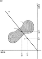
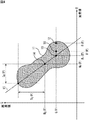
始めに、本発明の概要について、図4を参照して説明する。図4の領域11は、図2に示したような緑色の領域と赤色の領域が徐々に交わっているエッジ部分を有する被写体を撮影して得られた色モザイク画像を元にして生成されたカラー画像の画素のR成分とG成分の分布を示している。図4において、横軸はR成分の値を示し、縦軸はG成分の値を示す。
【0035】
例えば、図4の点12を、生成されたカラー画像上に発生した画質劣化(偽色等)の画素に対応する点であると仮定する。以下、画質劣化の画素を補正画素Pと記述する。
【0036】
本発明においては、補正画素PのG成分G(P)が他の色成分R(P),B(P)よりも被写体が本来有している色を比較的正確に復元されているとの仮定に基づき、補正画素PのG成分G(P)を基準として、補正画素PのR成分G(P)およびB成分B(P)を、周囲の画素の標準偏差に対応する直線15に隣接するように補正する。
【0037】
なお、以下においては、補正画素PのG成分G(P)を基準として、補正画素PのR成分R(P)を補正する処理についてだけ説明し、同様の処理である補正画素PのB成分B(P)を補正する処理の説明は省略する。
【0038】
具体的には、補正画像PのG成分G(P)を次式(1)に適用して、図4の点13のR成分の補正信号Rr(P)を算出し、算出した補正信号Rr(P)と補正前のR(P)を、次式(2)に基づいて合成して、補正画素Pの補正後のR成分R’(P)とする。
Rr(P)
=Sgn(P)・{G(P)−MG(P)}・SR(P)/SG(P)+MR(P)・・・(1)
R’(P)=αRr(P)+(1−α)・R(P) ・・・(2)
【0039】
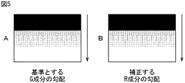
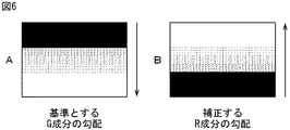
なお、Sgn(P)は、補正画素Pの周辺の基準とするG成分と、補正するR成分の相関に応じて−1,0,1のいずれかの値となる相関係数符号である。例えば、図5に示すように、基準とするG成分の勾配と補正するR成分の勾配が同一方向である場合、正の相関が高いとしてSgn(P)=1とする。また、図6に示すように、基準とするG成分の勾配と補正するR成分の勾配が逆方向である場合、負の相関が高いとしてSgn(P)=−1とする。さらに、基準とするG成分の勾配と補正するR成分の勾配が垂直である場合、相関が低いとしてSgn(P)=0とする。
【0040】
MG(P)は、補正画素Pの周辺の画素のG成分の平均値(図4の点14)である。MR(P)は、補正画素Pの周辺の画素のR成分の平均値(図4の点14)である。SG(P)は、補正画素Pの周辺の画素のG成分の標準偏差である。SR(P)は、補正画素Pの周辺の画素のR成分の標準偏差である。SR(P)/SG(P)は、図4の直線15の傾きに相当する。αは、0から1までの値をとる合成係数である。
【0041】
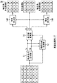
次に、図7は、本発明の一実施の形態であるディジタルスチルカメラの構成例を示している。当該ディジタルスチルカメラは、大別して光学系、信号処理系、記録系、表示系、および制御系から構成される。
【0042】
光学系は、被写体の光画像を集光するレンズ21、光画像の光量を調整する絞り22、および、集光された光画像を光電変換して電気信号に変換する、RGBのベイヤ配列等を成す色フィルタが設けられた単板式CCDイメージセンサ24から構成される。なお、色フィルタのパターンは、RGBのベイヤ配列以外であってもよい。
【0043】
信号処理系は、CCDイメージセンサ24からの電気信号をサンプリングすることによってノイズを低減させる相関2重サンプリング回路(CDS:Correlated Double Sampling)25、相関2重サンプリング回路25が出力するアナログ信号をディジタル信号に変換するA/Dコンバータ26、A/Dコンバータ26から入力されるディジタル信号に所定の画像処理(後述)を施す画像処理部27から構成される。なお、画像処理部27に入力されるディジタル信号が、上述した色モザイク画像に相当する。
【0044】
記録系は、画像処理部27が処理した画像信号を符号化してメモリ29に記録し、また、読み出して復号し、画像処理部27に供給するCODEC(Compression/Decompression)28、および、画像信号を記憶するメモリ29から構成される。
【0045】
表示系は、画像処理部27が処理した画像信号をアナログ化するD/Aコンバータ30、アナログ化された画像信号を後段のディスプレイ32に適合する形式のビデオ信号にエンコードするビデオエンコーダ31、および、入力されるビデオ信号に対応する画像を表示することによってファインダとして機能するLCD(Liquid Crystal Display)等よりなるディスプレイ32から構成される。
【0046】
制御系は、CCDイメージセンサ24乃至画像処理部27の動作タイミングを制御するタイミングジェネレータ(TG)23、ユーザによるシャッタ操作やその他のコマンドを入力するための操作入力部33、および、ドライブ35を制御して磁気ディスク36、光ディスク37、光磁気ディスク38、または半導体メモリ39に記憶されている制御用プログラムを読み出し、読み出した制御用プログラム、操作入力部33から入力されるユーザからのコマンド等に基づいてディジタルスチルカメラの全体を制御するCPU(Central Processing Unit)などよりなる制御部34から構成される。
【0047】
当該ディジタルスチルカメラにおいて、被写体の光学画像(入射光)は、レンズ21および絞り22を介してCCDイメージセンサ24に入射され、CCDイメージセンサ24によって光電変換されて電気信号となる。得られた電気信号は、相関2重サンプリング回路25によってノイズ成分が除去され、A/Dコンバータ26によってディジタル化された後、画像処理部27が内蔵する画像メモリに一時格納される。
【0048】
なお、通常の状態では、タイミングジェネレータ23による信号処理系に対する制御により、画像処理部27が内蔵する画像メモリには、一定のフレームレートで絶えず画像信号が上書きされるようになされている。画像処理部27が内蔵する画像メモリの画像信号は、D/Aコンバータ30によってアナログ信号に変換され、ビデオエンコーダ31によってビデオ信号に変換されて対応する画像がディスプレイ32に表示される。
【0049】
ディスプレイ32は、当該ディジタルスチルカメラのファインダの役割も担っている。ユーザが操作入力部33に含まれるシャッタボタンを押下した場合、制御部34は、タイミングジェネレータ23に対し、シャッタボタンが押下された直後の画像信号を保持するように、すなわち、画像処理部27の画像メモリに画像信号が上書きされないように信号処理系を制御する。画像処理部27の画像メモリに保持された画像データは、CODEC28によって符号化されてメモリ29に記録される。以上のようなディジタルスチルカメラの動作によって、1枚の画像データの取り込みが完了する。
【0050】
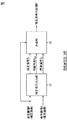
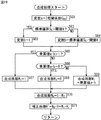
次に、図8は、画像処理部27の構成例を示している。色差信号生成部51は、上段から入力される色モザイク画像を元に、対応する色差信号Cr,Cbを生成して輝度成分生成部52および色空間変換部53に出力する。輝度画像生成部52は、上段から入力される色モザイク画像、および色差信号生成部51から入力される色差信号Cr,Cbを元に、全ての画素が輝度成分を有する輝度画像Yを生成して色空間変換部52に出力する。色空間変換部53は、輝度画像生成部52から入力される輝度画像Yの全ての画素それぞれを、色差信号生成部51から入力される色差信号Cr,Cbに基づいて、R成分、G成分、およびB成分に変換することにより、単色画像R,G,Bを生成する。なお、この段階で生成された単色画像R,G,Bのうちの単色画像R,Bには、偽色等の画像劣化が生じている可能性がある。
【0051】
偽色補正部54Rは、単色画像Gを基準として単色画像Rを補正し、補正済み単色画像R’を出力する。偽色補正部54Bは、単色画像Gを基準として単色画像Bを補正し、補正済み単色画像B’を出力する。
【0052】
図9は、図8の偽色補正部54Rの構成例を示している。補正信号出力部61は、上段の色空間変換部53によって生成された単色画像G,Rに基づき、各画素にそれぞれ対応する補正信号Rr、相関係数CRG、標準偏差SGを算出して合成部62に出力する。
【0053】
合成部62は、上段の色空間変換部53によって生成された単色画像Rの各画素について、相関係数CRGおよび標準偏差SGに基づいて補正信号出力部61から入力される補正信号Rrと合成することにより補正済単色画像R’を生成する。
【0054】
なお、合成部62を省略して、補正信号出力部61によって算出される補正信号Rrをそのまま偽色補正部54Rの出力としてもよい。
【0055】
偽色補正部54Bの構成例は、図9に示した偽色補正部54Rの構成例と同様であるので、その説明は省略する。
【0056】
図10は、図9の補正信号出力部61の構成例を示している。平均画素算出部71は、単色画像Rの全ての画素を順次注目し、注目画素Pを中心とする所定の領域に存在する複数の画素の値(すなわち、R成分)の平均MR(P)を算出して加算部75に出力する。なお、当該「所定の領域」と、以下の説明において記述する「所定の領域」は、同一のサイズである。
【0057】
平均画素算出部72は、単色画像Gの全ての画素を順次注目し、注目画素Pを中心とする所定の領域に存在する複数の画素の値(すなわち、G成分)の平均MG(P)を算出して減算部73に出力する。減算部73は、単色画像Gの全ての画素を順次注目し、注目画素Pの値G(P)から、平均画素算出部72から入力される注目画素に対応する平均MG(P)を減算し、差分信号{G(P)−MG(P)}として補正値算出部74に出力する。
【0058】
補正値算出部74は、単色画像R,G、および減算部73から入力される差分信号に基づき、各注目画素にそれぞれ対応する補正値を算出して加算部75に出力する。ここで、補正値は、式(1)の右辺の一部
Sgn(P)・{G(P)−MG(P)}・SR(P)/SG(P)
である。
【0059】
また、補正値算出部74は、各注目画素にそれぞれ対応する相関係数CRGおよび標準偏差SGを算出する。
【0060】
加算部75は、平均画素算出部71から入力される注目画素に対応する平均MR(P)に、補正値算出部74からの補正値を加算して補正信号Rrを算出する。
【0061】
図11は、図10の補正値算出部74の第1の構成例を示している。標準偏差算出部81は、単色画像Rの全ての画素を順次注目し、注目画素Pを中心とする所定の領域に存在する複数の画素の値(すなわち、R成分)の標準偏差SR(P)を算出して除算部83に出力する。標準偏差算出部82は、単色画像Gの全ての画素を順次注目し、注目画素Pを中心とする所定の領域に存在する複数の画素の値(すなわち、G成分)の標準偏差SG(P)を算出して除算部83に出力する。算出された標準偏差SG(P)は、後段の合成部62にも出力される。
【0062】
除算部83は、標準偏差算出部81から入力される標準偏差SR(P)を、標準偏差算出部82から入力される標準偏差SG(P)で除算し、標準偏差比SR(P)/SG(P)を乗算部85に出力する。相関係数符号判定部84は、単色画像R,Gの全ての画素を順次注目し、注目画素Pに対応する相関係数符号Sgn(P)を算出して乗算部85に出力する。
【0063】
乗算部85は、除算部83からの標準偏差比に、相関係数符号判定部84からの相関係数符号を乗算し、倍率信号{Sgn(P)・SR(P)/SG(P)}として乗算部86に出力する。乗算部86は、乗算部85からの倍率信号に、前段の減算部73からの差分信号を乗算し、補正値[Sgn(P)・{G(P)−MG(P)}・SR(P)/SG(P)]として後段の加算部75に出力する。
【0064】
図12は、図11の相関係数符号判定部84の構成例を示している。標準偏差算出部91は、単色画像Rの全ての画素を順次注目し、注目画素Pを中心とする所定の領域に存在する複数の画素の値(すなわち、R成分)の標準偏差SR(P)を算出して乗算部93および相関係数演算部96に出力する。標準偏差算出部92は、単色画像Gの全ての画素を順次注目し、注目画素Pを中心とする所定の領域に存在する複数の画素の値(すなわち、G成分)の標準偏差SG(P)を算出して乗算部93および相関係数演算部96に出力する。
【0065】
乗算部93は、標準偏差算出部91からの標準偏差SR(P)と標準偏差算出部91からの標準偏差SG(P)を乗算し、乗算値SR(P)・SG(P)を相関係数演算部96に出力する。
【0066】
平均画素算出部94は、単色画像Rの全ての画素を順次注目し、注目画素Pを中心とする所定の領域に存在する複数の画素の値(すなわち、R成分)の平均MR(P)を算出して相関係数演算部96に出力する。平均画素算出部95は、単色画像Gの全ての画素を順次注目し、注目画素Pを中心とする所定の領域に存在する複数の画素の値(すなわち、G成分)の平均MG(P)を算出して相関係数演算部96に出力する。
【0067】
相関係数演算部96は、注目画素に対応する相関係数CRG(P)を算出し、符号決定部97に出力する。具体的には、乗算部93からの乗算値が0である場合、相関係数CRG(P)を0とする。反対に、乗算部93からの乗算値が0ではない場合、次式(3)に従って相関係数CRG(P)を算出する。
CRG(P)=(ΣRG−MR(P)・MG(P))/(SR(P)・SG(P))・・・(3)
【0068】
ここで、ΣRGは、単色画像Rの注目画素を中心とする所定の領域に存在する複数(σとする)の画素と、単色画像Gの注目画素を中心とする所定の領域に存在する複数の画素との同一座標に位置する画素同士の積の総和を、所定の領域に存在する画素の数σで除算した値である。
【0069】
なお、相関係数演算部96によって算出された相関係数CRG(P)は後段の合成部62にも供給される。
【0070】
符号決定部97は、相関係数演算部96からの相関係数CRG(P)に基づき、各注目画素に対して相関係数符号Sgn(P)を決定し、後段の乗算部85に出力する。具体的には、相関係数CRG(P)が0よりも小さい場合、相関係数符号Sgn(P)を−1とする。相関係数CRG(P)が0よりも大きい場合、相関係数符号Sgn(P)を1とする。また、相関係数CRG(P)が0である場合、相関係数符号Sgn(P)を0とする。
【0071】
図13は、図9の合成部62の構成例を示している。合成係数算出部101は、補正信号出力部61からの相関係数CRG(P)および標準偏差SG(P)に基づき、各注目画素Pに対応する合成係数W1(P)を算出して混合部102に出力する。具体的には、相関係数CRG(P)の絶対値を変数aとする。一方、標準偏差SG(P)が所定の閾値Aよりも大きい場合、変数bを1とする。反対に、標準偏差SG(P)が所定の閾値Aよりも大きくない場合、変数bを、標準偏差SG(P)を閾値Aで除算した除算値(SG(P)/閾値A)とする。そして、変数aと変数bの乗算値a・bが1よりも大きい場合、合成係数W1を1とする。乗算値a・bが0である場合、合成係数W1を0とする。また、乗算値a・bが0以上1以下である場合、乗算値a・bを合成係数W1とする。
【0072】
混合部102は、上段の色空間変換部53によって生成された単色画像Rの全ての画素R(P)と補正信号出力部61から入力される対応する補正信号Rr(P)とを、合成係数W1を用いた次式(4)に従って加重加算し、補正済単色画像R’を生成する。
R’(P)=W0・R(P)+W1・R’(P) ・・・(4)
ただし、合成係数W0は(1−W1)である。
【0073】
なお、上述した各部の説明において、例えば、標準偏差SR(P)を標準偏差算出部81と標準偏差算出部91がそれぞれ独立して演算しているように、同一の演算を異なる信号処理部がそれぞれ独立して演算しているが、任意の信号処理部だけがその演算を実行し、他の信号処理部はその演算結果を流用するようにしてもよい。
【0074】
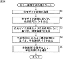
次に、画像処理部27の動作について、図14のフローチャートを参照して説明する。
【0075】
ステップS1において、画像処理部27は、A/Dコンバータ26が出力する色モザイク画像を取得し、色差信号生成部51および輝度画像生成部52に供給する。ステップS2において、色差信号生成部51は、上段から入力された色モザイク画像を元に、対応する色差信号Cr,Cbを生成して輝度成分生成部52および色空間変換部53に出力する。ステップS3において、輝度画像生成部52は、上段から入力された色モザイク画像、および色差信号生成部51から入力された色差信号Cr,Cbに基づき、全ての画素が輝度成分を有する輝度画像Yを生成して色空間変換部52に出力する。
【0076】
ステップS4において、色空間変換部53は、輝度画像生成部52から入力された輝度画像Yの全ての画素それぞれを、色差信号生成部51から入力される色差信号Cr,Cbに基づいて、R成分、G成分、およびB成分に変換することにより、単色画像R,G,Bを生成する。
【0077】
ステップS5において、偽色補正部54Rは、単色画像Gを基準として単色画像Rを補正し、補正済み単色画像R’を出力する。また、偽色補正部54Bは、単色画像Gを基準として単色画像Bを補正し、補正済み単色画像B’を出力する。以下、適宜、単色画像Gを基準画像Gとも記述し、単色画像Rを補正画像Rとも記述する。
【0078】
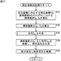
ステップS5における偽色補正部54Rによる偽色補正処理の詳細について、図15のフローチャートを参照して説明する。なお、偽色補正部54Rによる偽色補正処理も同様であるので、その説明は省略する。
【0079】
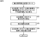
ステップS11において、補正信号出力部61は、上段の色空間変換部53によって生成された単色画像G,Rに全ての画素を順次、注目画素Pとし、注目画素Pに対応する補正信号Rr(P)、相関係数CRG(P)、標準偏差SG(P)を算出して合成部62に出力する。ステップS11における、補正信号出力部61による注目画素Pに対応する補正信号Rr(P)を算出する処理について、図16を参照して説明する。
【0080】
ステップS21において、平均画素算出部71は、補正画像Rの注目画素Pを中心とする所定の領域に存在する複数の画素の値(すなわち、R成分)の平均MR(P)を算出して加算部75に出力する。一方、平均画素算出部72は、基準画像Gの注目画素Pを中心とする所定の領域に存在する複数の画素の値(すなわち、G成分)の平均MG(P)を算出して減算部73に出力する。
【0081】
ステップS22において、減算部73は、基準画像Gの注目画素Pの値G(P)から、平均画素算出部72から入力された平均MG(P)を減算し、差分信号{G(P)−MG(P)}として補正値算出部74に出力する。
【0082】
ステップS23において、補正値算出部74は、単色画像R,G、および減算部73から入力された差分信号に基づき、注目画素に対応する補正値[Sgn(P)・{G(P)−MG(P)}・SR(P)/SG(P)]を算出して加算部75に出力する。ステップS23における補正値算出部74による補正値算出処理の詳細について、図17のフローチャートを参照して説明する。
【0083】
ステップS31において、標準偏差算出部81は、補正画像Rの注目画素Pを中心とする所定の領域に存在する複数の画素の値(すなわち、R成分)の標準偏差SR(P)を算出して除算部83に出力する。一方、標準偏差算出部82は、基準画像Gの注目画素Pを中心とする所定の領域に存在する複数の画素の値(すなわち、G成分)の標準偏差SG(P)を算出して除算部83に出力する。ステップS32において、除算部83は、標準偏差算出部81から入力された標準偏差SR(P)を、標準偏差算出部82から入力された標準偏差SG(P)で除算し、標準偏差比SR(P)/SG(P)を乗算部85に出力する。
【0084】
一方、相関係数符号判定部84は、ステップS33において、単色画像R,Gの注目画素Pに対応する相関係数符号Sgn(P)を算出して乗算部85に出力する。なお、ステップS33の処理は、ステップS31,S32の処理と平行して実行することができる。
【0085】
ステップS33における相関係数符号判定部84による相関係数符号判定処理の詳細について、図18を参照して説明する。
【0086】
ステップS41において、標準偏差算出部91は、補正画像Rの注目画素Pを中心とする所定の領域に存在する複数の画素の値(すなわち、R成分)の標準偏差SR(P)を算出して乗算部93および相関係数演算部96に出力する。一方、標準偏差算出部92は、基準画像Gの注目画素Pを中心とする所定の領域に存在する複数の画素の値(すなわち、G成分)の標準偏差SG(P)を算出して乗算部93および相関係数演算部96に出力する。乗算部93は、標準偏差算出部91からの標準偏差SR(P)と標準偏差算出部91からの標準偏差SG(P)を乗算し、乗算値SR(P)・SG(P)を相関係数演算部96に出力する。
【0087】
ステップS42において、相関係数演算部96は、乗算部93からの乗算値が0であるか否かを判定する。乗算部93からの乗算値が0ではないと判定された場合、処理はステップS43に進む。
【0088】
ステップS43において、平均画素算出部94は、補正画像Rの注目画素Pを中心とする所定の領域に存在する複数の画素の値(すなわち、R成分)の平均MR(P)を算出して相関係数演算部96に出力する。一方、平均画素算出部95は、基準画像Gの注目画素Pを中心とする所定の領域に存在する複数の画素の値(すなわち、G成分)の平均MG(P)を算出して相関係数演算部96に出力する。ステップS44において、相関係数演算部96は、式(3)に従って相関係数CRG(P)を算出する。
【0089】
反対に、ステップS42において、乗算部93からの乗算値が0であると判定された場合、処理はステップS45に進む。ステップS45において、相関係数演算部96は、相関係数CRG(P)を0とする。
【0090】
ステップS46において、符号決定部97は、相関係数演算部96からの相関係数CRG(P)が0よりも小さいか否かを判定する。相関係数CRG(P)が0よりも小さいと判定された場合、処理はステップS47に進む。ステップS47において、符号決定部97は、相関係数符号Sgn(P)を−1とする。
【0091】
ステップS46において、相関係数CRG(P)が0よりも小さくないと判定された場合、処理はステップS48に進む。ステップS48において、符号決定部97は、相関係数CRG(P)が0よりも大きいか否かを判定する。相関係数CRG(P)が0よりも大きいと判定された場合、処理はステップS49に進む。ステップS49において、符号決定部97は、相関係数符号Sgn(P)を1とする。
【0092】
ステップS48において、相関係数CRG(P)が0よりも大きくない、すなわち、相関係数CRG(P)が0であると判定された場合、処理はステップS50に進む。ステップS50において、符号決定部97は、相関係数符号Sgn(P)を0とする。
【0093】
以上のようにして、相関係数符号Sgn(P)が−1,0,1のいずれかに判定された後、処理は、図17のステップS34にリターンする。
【0094】
ステップS34において、乗算部85は、除算部83からの標準偏差比に、相関係数符号判定部84からの相関係数符号を乗算し、倍率信号{Sgn(P)・SR(P)/SG(P)}として乗算部86に出力する。ステップS35において、乗算部86は、乗算部85からの倍率信号に、前段の減算部73からの差分信号を乗算し、注目画素に対応する補正値[Sgn(P)・{G(P)−MG(P)}・SR(P)/SG(P)]として後段の加算部75に出力する。
【0095】
このようにして注目画素に対応する補正値が算出された後、処理は図16のステップS24にリターンする。
【0096】
ステップS24において、加算部75は、平均画素算出部71から入力された注目画素に対応する平均MR(P)に、補正値算出部74からの補正値を換算して補正信号Rrを算出する。
【0097】
処理は図15のステップS12にリターンする。ステップS12において、合成部62は、上段の色空間変換部53によって生成された単色画像Rの各画素と、補正信号出力部61から入力される各画素に対応する補正信号Rrを、相関係数CRGおよび標準偏差SGに基づいて合成することにより補正済単色画像R’を生成する。
【0098】
ステップS12における合成部62による合成処理の詳細について、図19のフローチャートを参照して説明する。ステップS61において、合成係数算出部101は、補正信号出力部61からの相関係数CRG(P)の絶対値|CRG(P)|を変数aに代入する。
【0099】
ステップS62において、合成係数算出部101は、標準偏差SG(P)が所定の閾値Aよりも大きいか否かを判定する。
標準偏差SG(P)が所定の閾値Aよりも大きいと判定された場合、処理はステップS63に進む。ステップS63において、合成係数算出部101は、変数bに1を代入する。
【0100】
反対に、ステップS62において、標準偏差SG(P)が所定の閾値Aよりも大きくないと判定された場合、処理はステップS64に進む。ステップS64において、合成係数算出部101は、変数bに、標準偏差SG(P)を閾値Aで除算した除算値(SG(P)/閾値A)を代入する。
【0101】
ステップS65において、合成係数算出部101は、変数aと変数bを乗算し、乗算値a・bが1よりも大きいか否かを判定する。乗算値a・bが1よりも大きいと判定された場合、処理はステップS66に進む。ステップS66において、合成係数算出部101は、合成係数W1を1とする。
【0102】
ステップS65において、乗算値a・bが1よりも大きくないと判定された場合、処理はステップS67に進む。ステップS67において、合成係数算出部101は、乗算値a・bが0であるか否かを判定する。乗算値a・bが0であると判定された場合、処理はステップS68に進む。ステップS68において、合成係数算出部101は、合成係数W1を0とする。
【0103】
ステップS67において、乗算値a・bが0ではないと判定された場合、処理はステップS69に進む。ステップS69において、合成係数算出部101は、合成係数W1に乗算値a・bを代入する。
【0104】
ステップS70において、混合部102は、合成係数算出部101からの合成係数W1を1から減算して合成係数W0を算出する。ステップS71において、混合部102は、式(4)に従い、上段の色空間変換部53によって生成された補正画像Rの注目画素R(P)と、補正信号出力部61からの補正信号Rr(P)とを加重加算して補正済単色画像R’の画素R’(P)を算出する。
【0105】
以上説明したような処理が、全ての画素が順次指定される注目画素に対して施されることにより、補正済単色画像R’が生成される。以上、画像処理部27の動作についての説明を終了する。
【0106】
ところで、補正値を加算部75に出力する補正値算出部74は、以下のように構成してもよい。
【0107】
図20は、図10の補正値算出部74の第2の構成例を示している。当該第2の構成例において、図11に示した補正値算出部74の第1の構成例と同様に動作する信号処理部については、同一の符号を付与しているので、その説明は省略する。当該第2の構成例においては、乗算部83の出力結果である、標準偏差比SR(P)/SG(P)が倍率信号として乗算部86に供給される。
【0108】
図21は、図10の補正値算出部74の第3の構成例を示している。当該第3の構成例において、図11に示した補正値算出部74の第1の構成例と同様に動作する信号処理部については、同一の符号を付与しているので、その説明は省略する。
【0109】
当該第3の構成例においては、相関係数符号判定部84の出力結果である、相関係数符号Sgn(P)が倍率信号として乗算部86に供給される。また、相関係数符号判定部84を構成する標準偏差算出部92によって算出された標準偏差SG(P)が、後段の合成部62に供給される。
【0110】
図22は、図10の補正値算出部74の第4の構成例を示している。当該第4の構成例において、図11に示した補正値算出部74の第1の構成例と同様に動作する信号処理部については、同一の符号を付与しているので、その説明は省略する。
【0111】
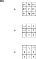
1次微分算出部111は、補正画像Rの注目画素に対して、ソーベル(Sobel)演算子を用いてベクトルGR(GRh,GRv)を算出する。具体的には、例えば、図23Aに示す3×3画素の中心を注目画素Pとし、この左上、上、右上、左、右、左下、下、および右下の画素の値を、それぞれ、Pa,Pb,Pc,Pd,Pe,Pf,Pg,およびPhとして、3×3画素のそれぞれに、図23Bの係数を乗算してその総和を、ベクトルGRの水平成分GRhとして算出する。また、3×3画素のそれぞれに、図23Cの係数を乗算してその総和を、ベクトルGRの垂直成分GRvとして算出する。
GRh=−Pa+Pc−2Pd+2Pe−Pf+Ph
GRv=−Pa−2Pb−Pc+Pf+2Pg+Ph
【0112】
1次微分算出部112は、1次微分算出部111と同様に、基準画像Rの注目画素に対して、ソーベル演算子を用いてベクトルGG(GGh,GGv)を算出する。
【0113】
内積演算部113は、1次微分算出部111からのベクトルGRと、1次微分算出部112からのベクトルGGとの内積(GRh・GGh+GRv・GGv)を算出し、倍率信号として乗算部86に出力する。
【0114】
図24は、図10の補正値算出部74の第5の構成例を示している。当該第5の構成例において、図22に示した補正値算出部74の第4の構成例と同様に動作する信号処理部については、同一の符号を付与しているので、その説明は省略する。
【0115】
絶対値比演算部121は、内積演算部113は、1次微分算出部111からのベクトルGRの絶対値と、1次微分算出部112からのベクトルGGとの絶対値と比|GR|/|GG|=√(GRh 2+GRv 2)/√(GGh 2+GGv 2)を算出し、倍率信号として乗算部86に出力する。
【0116】
以上、補正値算出部74の第2乃至第5の構成例についての説明を終了する。
【0117】
なお、本発明は、本実施の形態のようなディジタルスチルカメラの他、画像処理を実施するあらゆる機器に適用することが可能である。
【0118】
ところで、上述した一連の処理は、ハードウェアにより実行させることもできるが、ソフトウェアにより実行させることもできる。一連の処理をソフトウェアにより実行させる場合には、そのソフトウェアを構成するプログラムが、専用のハードウェアに組み込まれているコンピュータ、または、各種のプログラムをインストールすることで、各種の機能を実行することが可能な、例えば汎用のパーソナルコンピュータなどに、記録媒体からインストールされる。
【0119】
この記録媒体は、図7に示すように、コンピュータとは別に、ユーザにプログラムを提供するために配布される、プログラムが記録されている磁気ディスク36(フロッピディスクを含む)、光ディスク37(CD-ROM(Compact Disc-Read Only Memory)、DVD(Digital Versatile Disc)を含む)、光磁気ディスク38(MD(Mini Disc)を含む)、もしくは半導体メモリ39などよりなるパッケージメディアにより構成されるだけでなく、コンピュータに予め組み込まれた状態でユーザに提供される、プログラムが記録されているROMやハードディスクなどで構成される。
【0120】
なお、本明細書において、記録媒体に記録されるプログラムを記述するステップは、記載された順序に従って時系列的に行われる処理はもちろん、必ずしも時系列的に処理されなくとも、並列的あるいは個別に実行される処理をも含むものである。
【0121】
【発明の効果】
以上のように、本発明の画像処理装置および方法、並びにプログラムによれば、色モザイク画像を元に生成されたカラー画像に生じた色モアレや偽色を補正することが可能となる。
【図面の簡単な説明】
【図1】 RGBのベイヤ配列を示す図である。
【図2】エッジ画像の一例を示す図である。
【図3】図2のエッジ画像に対応する画素分布を示す図である。
【図4】本発明の概要を説明するための図である。
【図5】正の相関関係を有する画像例を示す図である。
【図6】負の相関関係を有する画像例を示す図である。
【図7】本発明を適用したディジタルスチルカメラの構成例を示すブロック図である。
【図8】画像処理部27の構成例を示すブロック図である。
【図9】図8の偽色補正部54Rの構成例を示すブロック図である。
【図10】図9の補正信号出力部61の構成例を示すブロック図である。
【図11】図10の補正値算出部74の第1の構成例を示すブロック図である。
【図12】図11の相関係数符号判定部84の構成例を示すブロック図である。
【図13】図9の合成部62の構成例を示すブロック図である。
【図14】画像処理部27の動作を説明するフローチャートである。
【図15】図14のステップS5における偽色補正処理を説明するフローチャートである。
【図16】図15のステップS11における補正信号算出処理を説明するフローチャートである。
【図17】図16のステップS23における補正値算出処理を説明するフローチャートである。
【図18】図17のステップS33における符号判定処理を説明するフローチャートである。
【図19】図15のステップS12における合成処理を説明するフローチャートである。
【図20】図10の補正値算出部74の第2の構成例を示すブロック図である。
【図21】図10の補正値算出部74の第3の構成例を示すブロック図である。
【図22】図10の補正値算出部74の第4の構成例を示すブロック図である。
【図23】図22の1次微分算出部111の動作を説明するための図である。
【図24】図10の補正値算出部74の第5の構成例を示すブロック図である。
【符号の説明】
27 画像処理部, 34 制御部, 36 磁気ディスク, 37 光ディスク, 38 光磁気ディスク, 39 半導体メモリ, 54R,54B 偽色補正部, 61 補正信号出力部, 62 合成部, 71,72 平均画素算出部, 74 補正値算出部, 81,82 標準偏差算出部, 86 乗算部, 91,92 標準偏差算出部, 94,95 平均画素算出部, 96 相関係数演算部, 97 符号判定部, 101 合成係数算出部, 102 混合部, 111,112 1次微分算出部, 113 内積演算部, 121 絶対値比演算部[0001]
BACKGROUND OF THE INVENTION
The present invention relates to an image processing apparatus and method, a recording medium, and a program. For example, an image processing apparatus suitable for use in suppressing image quality degradation that may occur in a color image generated based on a single-plate color image sensor. And a method, a recording medium, and a program.
[0002]
[Prior art]
For example, in an imaging apparatus using a single-plate solid-state imaging device such as a CCD (Charge Coupled Device), only a single spectral sensitivity can be obtained even if the image is taken as it is (that is, only a monochrome image can be obtained).
[0003]
Therefore, in order to obtain a color image using a single-plate solid-state imaging device, a predetermined pattern (for example, R (red) as shown in FIG. 1) is formed on the light receiving surface of the light receiving device corresponding to each pixel of the obtained image. , G (green), and B (blue) Bayer array) color filters are generally provided for photographing.
[0004]
The image obtained by this imaging is an image in which each pixel has only a single color component and has a mosaic shape with respect to color (hereinafter referred to as a color mosaic image). Furthermore, for each pixel of the color mosaic image, by interpolating other color components that the pixel does not have using surrounding pixels, all the pixels have all the color component colors. An image, that is, a color image is generated.
[0005]
However, as described above, when a color image is generated based on a color mosaic image, image degradation such as color moire may occur in the generated color image.
[0006]
For example, when an RGB Bayer array is provided in a single-plate type individual image pickup device and a color filter is provided, the obtained color mosaic image has different sampling positions for each color component, and its R component and B component are G The sampling frequency is halved compared to the component. As described above, when interpolation processing is performed using color mosaic images having different sampling positions and sampling frequencies for each color component, there is a difference in the sampling method for each color component, so the color generated by the interpolation processing is different. When each color component is compared for each pixel of an image, there may be a shift in phase and amplitude, which causes image quality degradation such as color moire.
[0007]
Therefore, conventionally, an image processing technique for generating a color image in which image deterioration is suppressed based on a color mosaic image has been proposed.
[0008]
For example, Japanese Patent Application Laid-Open No. 61-501424 discloses a method for restoring nonexistent color components by interpolation on the premise that the direction of the color (chrominance) of an object does not change so much in a local region (hereinafter referred to as “color”). , Described as a first conventional method). That is, in the first conventional method, it is assumed that the ratio of the R component and the G component in each of the two neighboring pixels x and y is the same, and the G component G (x) exists in the pixel x of the color mosaic image. Then, the R component R (x) of the nonexistent pixel x is calculated by the following equation using the ratio of the R component (y) and the G component (y) of the neighboring pixel y.
R (x) = G (x) .R (y) / G (y)
[0009]
However, in actuality, as the value of R (y) / G (y), the R component in the vicinity of the pixel x and the average of the ratio of the plurality of pixels having the component (R / G)LIs used.
R (x) = G (x) · (R / G)L
It becomes.
[0010]
Further, for example, US Pat. No. 4,716,455 discloses an R component in the vicinity of the pixel x and an average ratio (R / G) of a plurality of pixels having the component used in the first conventional method.LIs approximated by the ratio (RL / GL) of the low frequency component RL of the R component and the low frequency component GL of the G component (hereinafter referred to as a second conventional method).
[0011]
Since the low frequency component RL of the R component and the low frequency component GL of the G component used in the second conventional method can be calculated independently even if one pixel does not have both the R component and the G component. There is an advantage that it is not necessary to interpolate the G component first for all the pixels.
[0012]
[Problems to be solved by the invention]
As described above, in the first and second conventional methods, there is a local proportional relationship between the R component, G component, and B component of the pixel (or the R component, G component, and B component of the pixel). The interpolation is performed on the assumption that the ratio between is locally constant).
[0013]
Therefore, in the first and second conventional methods, for example, when there is an abrupt color change in the edge portion of the subject, there is still a problem that a color moire or false color still occurs there. there were.
[0014]
This will be specifically described. For example, as shown in FIG. 2, consider an image (hereinafter referred to as an edge image) obtained by photographing a subject having an edge portion where a green region and a red region gradually intersect. FIG. 3 shows the distribution of R and G components of the pixels constituting the edge image of FIG. In FIG. 3, the horizontal axis indicates the value of the R component, and the vertical axis indicates the value of the G component.
[0015]
[0016]
[0017]
Therefore, as in the first and second conventional methods, there is a local proportional relationship between the R component and the G component of the pixel (the ratio of the R component and the G component is locally constant). Assuming that the pixel P is on the
[0018]
As apparent from FIG. 3, the
[0019]
In addition, there is a problem that a technique for correcting a color image in which color moire or false color is generated to a color that the subject originally has does not exist.
[0020]
The present invention has been made in view of such a situation, and an object of the present invention is to make it possible to correct color moire and false color generated in a color image generated based on a color mosaic image.
[0021]
[Means for Solving the Problems]
The image processing apparatus according to the present invention calculates a first average pixel corresponding to a target pixel of a reference image in which all the pixels are generated based on a color mosaic image and have only the first color component. Average pixel calculation means and a second average pixel that is generated based on the color mosaic image and calculates a second average pixel corresponding to the target pixel of the corrected image in which all the pixels have only the second color component A calculation means; a difference signal calculation means for calculating a difference signal between the first average pixel and a target pixel of the reference image; a correction value calculation means for calculating a correction value based on the reference image, the correction image, and the difference signal; Adding means for adding a correction value to the second average pixel to generate a first correction pixel;A synthesis coefficient calculation unit that calculates a synthesis coefficient based on information calculated in the process of calculating a correction value; and a synthesis unit that synthesizes the target pixel of the corrected image and the first correction pixel based on the synthesis coefficient.It is characterized by including.
[0023]
The correction value calculation unit may include a magnification signal calculation unit that calculates a magnification signal based on the reference image and the correction image, and a multiplication unit that generates a correction value by multiplying the magnification signal by the difference signal. it can.
[0024]
The magnification signal calculating unit calculates a first standard deviation that calculates a first standard deviation corresponding to the target pixel of the reference image, and a second standard deviation that calculates the second standard deviation corresponding to the target pixel of the corrected image. A standard deviation ratio calculating means, a standard deviation ratio calculating means for calculating a standard deviation ratio by dividing the second standard deviation by the first standard deviation, and a correlation coefficient code based on the reference image and the corrected image. Correlation coefficient code determination means and multiplication means for multiplying the standard deviation ratio by the correlation coefficient code to generate a magnification signal can be included.
[0025]
The magnification signal calculating unit calculates a first standard deviation that calculates a first standard deviation corresponding to the target pixel of the reference image, and a second standard deviation that calculates the second standard deviation corresponding to the target pixel of the corrected image. Standard deviation calculating means, and dividing means for dividing the second standard deviation by the first standard deviation to generate a magnification signal.
[0026]
The magnification signal calculation means may include correlation coefficient code determination means for determining a correlation coefficient code based on the reference image and the corrected image and outputting the correlation coefficient code as a magnification signal.
[0027]
The magnification signal calculating means calculates a first primary derivative calculating means for calculating a first primary derivative corresponding to the target pixel of the reference image, and a second primary derivative corresponding to the target pixel of the corrected image. And second primary differential calculation means.
[0028]
The magnification signal calculation means may further include an inner product calculation means for calculating an inner product of the first primary differentiation and the second primary differentiation as a magnification signal.
[0029]
The magnification signal calculation means may further include absolute value ratio calculation means for generating a magnification signal by dividing the absolute value of the second primary differentiation by the absolute value of the first primary differentiation.
[0030]
The image processing method of the present invention calculates a first average pixel corresponding to a target pixel of a reference image in which all the pixels are generated based on a color mosaic image and have only the first color component. An average pixel calculating step and a second average pixel which is generated based on the color mosaic image and calculates a second average pixel corresponding to the target pixel of the corrected image in which all pixels have only the second color component A calculation step; a difference signal calculation step for calculating a difference signal between the first average pixel and a target pixel of the reference image; a correction value calculation step for calculating a correction value based on the reference image, the correction image, and the difference signal; An addition step of adding a correction value to the second average pixel to generate a first correction pixel;A synthesis coefficient calculation unit that calculates a synthesis coefficient based on information calculated in the process of calculating a correction value; and a synthesis unit that synthesizes the target pixel of the corrected image and the first correction pixel based on the synthesis coefficient.It is characterized by including.
[0031]
The program of the recording medium of the present invention calculates a first average pixel corresponding to a target pixel of a reference image in which all the pixels are generated based on a color mosaic image and have only the first color component. And calculating a second average pixel corresponding to the target pixel of the corrected image in which all pixels have only the second color component, which is generated based on the color mosaic image. A pixel calculation step, a difference signal calculation step for calculating a difference signal between the first average pixel and the target pixel of the reference image, and a correction value calculation step for calculating a correction value based on the reference image, the correction image, and the difference signal And an adding step for adding a correction value to the second average pixel to generate a first correction pixel;A synthesis coefficient calculation unit that calculates a synthesis coefficient based on information calculated in the process of calculating a correction value; and a synthesis unit that synthesizes the target pixel of the corrected image and the first correction pixel based on the synthesis coefficient.It is characterized by including.
[0032]
The program according to the present invention generates a first average pixel that is generated based on a color mosaic image and calculates a first average pixel corresponding to a target pixel of a reference image in which all pixels have only the first color component. A calculation step and a second average pixel calculation step of calculating a second average pixel corresponding to the target pixel of the corrected image in which all the pixels have only the second color component generated based on the color mosaic image A difference signal calculation step for calculating a difference signal between the first average pixel and a target pixel of the reference image, a correction value calculation step for calculating a correction value based on the reference image, the correction image, and the difference signal; An addition step of adding a correction value to the two average pixels to generate a first correction pixel;A synthesis coefficient calculation unit that calculates a synthesis coefficient based on information calculated in the process of calculating a correction value; and a synthesis unit that synthesizes the target pixel of the corrected image and the first correction pixel based on the synthesis coefficient.Is executed by a computer.
[0033]
In the image processing apparatus, method, and program of the present invention, the first average pixel corresponding to the target pixel of the reference image in which all the pixels have only the first color component, generated based on the color mosaic image The second average pixel corresponding to the target pixel of the corrected image, in which all the pixels are generated based on the color mosaic image and have only the second color component, is calculated, and the first average pixel and A difference signal from the target pixel of the reference image is calculated, and a correction value is calculated based on the reference image, the corrected image, and the difference signal. Further, a correction value is added to the second average pixel to generate a first correction pixel.Furthermore, a synthesis coefficient is calculated based on the information calculated in the process of calculating the correction value, and the target pixel of the corrected image and the first correction pixel are synthesized based on the synthesis coefficient.
[0034]
DETAILED DESCRIPTION OF THE INVENTION
First, the outline of the present invention will be described with reference to FIG. A
[0035]
For example, it is assumed that the
[0036]
In the present invention, it is said that the G component G (P) of the correction pixel P restores the color inherent to the subject relatively accurately than the other color components R (P) and B (P). Based on the assumption, with reference to the G component G (P) of the correction pixel P, the R component G (P) and the B component B (P) of the correction pixel P are adjacent to the straight line 15 corresponding to the standard deviation of the surrounding pixels. Correct as follows.
[0037]
In the following, only the process of correcting the R component R (P) of the correction pixel P will be described with reference to the G component G (P) of the correction pixel P, and the B component of the correction pixel P, which is a similar process, will be described. A description of the process of correcting B (P) is omitted.
[0038]
Specifically, the G component G (P) of the corrected image P is applied to the following equation (1) to calculate the correction signal Rr (P) of the R component at the
Rr (P)
= Sgn (P) · {G (P) -MG(P)} ・ SR(P) / SG(P) + MR(P) ... (1)
R ′ (P) = αRr (P) + (1−α) · R (P) (2)
[0039]
Sgn (P) is a correlation coefficient code that takes a value of -1, 0, 1 depending on the correlation between the reference G component around the correction pixel P and the R component to be corrected. For example, as shown in FIG. 5, when the gradient of the reference G component and the gradient of the R component to be corrected are in the same direction, it is assumed that the positive correlation is high and Sgn (P) = 1. Further, as shown in FIG. 6, when the gradient of the reference G component and the gradient of the R component to be corrected are in the opposite direction, it is assumed that the negative correlation is high and Sgn (P) = − 1. Further, when the gradient of the reference G component and the gradient of the R component to be corrected are perpendicular, it is assumed that the correlation is low and Sgn (P) = 0.
[0040]
MG(P) is the average value of the G components of the pixels around the correction pixel P (
[0041]
Next, FIG. 7 shows a configuration example of a digital still camera which is an embodiment of the present invention. The digital still camera is roughly composed of an optical system, a signal processing system, a recording system, a display system, and a control system.
[0042]
The optical system includes a
[0043]
The signal processing system includes a correlated double sampling circuit (CDS) 25 that reduces noise by sampling an electrical signal from the
[0044]
The recording system encodes the image signal processed by the
[0045]
The display system includes a D /
[0046]
The control system controls a timing generator (TG) 23 that controls the operation timing of the
[0047]
In the digital still camera, an optical image (incident light) of a subject is incident on a
[0048]
In a normal state, the image signal built in the
[0049]
The
[0050]
Next, FIG. 8 shows a configuration example of the
[0051]
The false
[0052]
FIG. 9 shows a configuration example of the false
[0053]
The
[0054]
Note that the
[0055]
The configuration example of the false
[0056]
FIG. 10 shows a configuration example of the correction
[0057]
The average
[0058]
The correction value calculation unit 74 calculates a correction value corresponding to each pixel of interest based on the monochrome images R and G and the difference signal input from the subtraction unit 73 and outputs the correction value to the
Sgn (P) · {G (P) -MG(P)} ・ SR(P) / SG(P)
It is.
[0059]
Further, the correction value calculation unit 74 has a correlation coefficient C corresponding to each target pixel.RGAnd standard deviation SGIs calculated.
[0060]
The adding
[0061]
FIG. 11 shows a first configuration example of the correction value calculation unit 74 of FIG. The standard
[0062]
The
[0063]
Multiplying
[0064]
FIG. 12 shows a configuration example of the correlation coefficient
[0065]
The multiplication unit 93 calculates the standard deviation S from the standard deviation calculation unit 91.R(P) and the standard deviation S from the standard
[0066]
The average
[0067]
The correlation
CRG(P) = (ΣRG-MR(P) ・ MG(P)) / (SR(P) ・ SG(P)) ... (3)
[0068]
Here, ΣRG is a plurality of pixels (sigma) existing in a predetermined area centered on the target pixel of the monochrome image R and a plurality of pixels existing in a predetermined area centered on the target pixel of the monochrome image G. This is a value obtained by dividing the sum of products of pixels located at the same coordinates with the pixel by the number σ of pixels existing in a predetermined area.
[0069]
The correlation coefficient C calculated by the correlation coefficient calculation unit 96RG(P) is also supplied to the subsequent combining
[0070]
The
[0071]
FIG. 13 shows a configuration example of the combining
[0072]
The
R ′ (P) = W0・ R (P) + W1・ R '(P) (4)
However, the composite coefficient W0Is (1-W1).
[0073]
In the above description of each part, for example, the standard deviation SRAs in (P), the standard
[0074]
Next, the operation of the
[0075]
In step S <b> 1, the
[0076]
In step S <b> 4, the color
[0077]
In step S5, the false
[0078]
Details of the false color correction processing by the false
[0079]
In step S <b> 11, the correction
[0080]
In step S <b> 21, the average pixel calculation unit 71 calculates the average M of the values (that is, R components) of a plurality of pixels existing in a predetermined region centered on the target pixel P of the corrected image R.R(P) is calculated and output to the
[0081]
In step S <b> 22, the subtraction unit 73 calculates the average M input from the average
[0082]
In step S23, the correction value calculation unit 74, based on the monochromatic images R and G and the difference signal input from the subtraction unit 73, the correction value [Sgn (P) · {G (P) −M corresponding to the target pixel.G(P)} ・ SR(P) / SG(P)] is calculated and output to the
[0083]
In step S <b> 31, the standard
[0084]
On the other hand, the correlation coefficient
[0085]
Details of the correlation coefficient code determination processing by the correlation coefficient
[0086]
In step S <b> 41, the standard
[0087]
In step S <b> 42, the correlation
[0088]
In step S43, the average
[0089]
Conversely, if it is determined in step S42 that the multiplication value from the multiplier 93 is 0, the process proceeds to step S45. In step S45, the
[0090]
In step S <b> 46, the
[0091]
In step S46, the correlation coefficient CRGIf it is determined that (P) is not smaller than 0, the process proceeds to step S48. In step S48, the
[0092]
In step S48, the correlation coefficient CRG(P) is not greater than 0, ie correlation coefficient CRGIf it is determined that (P) is 0, the process proceeds to step S50. In step S50, the
[0093]
As described above, after the correlation coefficient code Sgn (P) is determined to be any one of -1, 0, and 1, the process returns to step S34 in FIG.
[0094]
In step S34, the
[0095]
After the correction value corresponding to the target pixel is calculated in this way, the process returns to step S24 in FIG.
[0096]
In step S <b> 24, the
[0097]
The process returns to step S12 in FIG. In step S <b> 12, the synthesizing
[0098]
Details of the composition processing by the
[0099]
In step S62, the synthesis
Standard deviation SGIf it is determined that (P) is greater than the predetermined threshold A, the process proceeds to step S63. In step S63, the synthesis
[0100]
Conversely, in step S62, the standard deviation SGIf it is determined that (P) is not greater than the predetermined threshold A, the process proceeds to step S64. In step S64, the synthesis
[0101]
In step S65, the synthesis
[0102]
If it is determined in step S65 that the multiplication value a · b is not greater than 1, the process proceeds to step S67. In step S67, the composite
[0103]
If it is determined in step S67 that the multiplication value a · b is not 0, the process proceeds to step S69. In step S69, the synthesis
[0104]
In step S <b> 70, the
[0105]
The corrected monochromatic image R ′ is generated by performing the processing as described above on the target pixel in which all the pixels are sequentially designated. This is the end of the description of the operation of the
[0106]
By the way, the correction value calculation unit 74 that outputs the correction value to the
[0107]
FIG. 20 shows a second configuration example of the correction value calculation unit 74 of FIG. In the second configuration example, the same reference numerals are given to the signal processing units that operate in the same manner as the first configuration example of the correction value calculation unit 74 shown in FIG. . In the second configuration example, the standard deviation ratio S, which is the output result of the multiplier 83.R(P) / SG(P) is supplied to the
[0108]
FIG. 21 shows a third configuration example of the correction value calculation unit 74 in FIG. In the third configuration example, the signal processing unit that operates in the same manner as the first configuration example of the correction value calculation unit 74 illustrated in FIG. .
[0109]
In the third configuration example, the correlation coefficient code Sgn (P), which is the output result of the correlation coefficient
[0110]
FIG. 22 shows a fourth configuration example of the correction value calculation unit 74 of FIG. In the fourth configuration example, the signal processing unit that operates in the same manner as the first configuration example of the correction value calculation unit 74 shown in FIG. .
[0111]
The primary
GRh= −Pa + Pc−2Pd + 2Pe−Pf + Ph
GRv= −Pa−2Pb−Pc + Pf + 2Pg + Ph
[0112]
Similar to the primary
[0113]
The inner
[0114]
FIG. 24 shows a fifth configuration example of the correction value calculation unit 74 of FIG. In the fifth configuration example, the signal processing unit that operates in the same manner as the fourth configuration example of the correction value calculation unit 74 illustrated in FIG. .
[0115]
The absolute value
[0116]
This is the end of the description of the second to fifth configuration examples of the correction value calculation unit 74.
[0117]
Note that the present invention can be applied to any device that performs image processing in addition to the digital still camera as in the present embodiment.
[0118]
By the way, the series of processes described above can be executed by hardware, but can also be executed by software. When a series of processing is executed by software, a program constituting the software may execute various functions by installing a computer incorporated in dedicated hardware or various programs. For example, it is installed from a recording medium in a general-purpose personal computer or the like.
[0119]
As shown in FIG. 7, this recording medium is distributed to provide a program to the user separately from the computer, and includes a magnetic disk 36 (including a floppy disk) on which the program is recorded, an optical disk 37 (CD- ROM (Compact Disc-Read Only Memory), DVD (including Digital Versatile Disc)), magneto-optical disc 38 (including MD (Mini Disc)), or
[0120]
In the present specification, the step of describing the program recorded in the recording medium is not limited to the processing performed in time series according to the described order, but is not necessarily performed in time series, either in parallel or individually. The process to be executed is also included.
[0121]
【The invention's effect】
As described above, according to the image processing apparatus, method, and program of the present invention, it is possible to correct color moire and false color generated in a color image generated based on a color mosaic image.
[Brief description of the drawings]
FIG. 1 is a diagram showing an RGB Bayer array.
FIG. 2 is a diagram illustrating an example of an edge image.
FIG. 3 is a diagram illustrating a pixel distribution corresponding to the edge image of FIG. 2;
FIG. 4 is a diagram for explaining the outline of the present invention.
FIG. 5 is a diagram illustrating an example of an image having a positive correlation.
FIG. 6 is a diagram illustrating an example of an image having a negative correlation.
FIG. 7 is a block diagram illustrating a configuration example of a digital still camera to which the present invention is applied.
8 is a block diagram illustrating a configuration example of an
9 is a block diagram illustrating a configuration example of a false
10 is a block diagram illustrating a configuration example of a correction
11 is a block diagram illustrating a first configuration example of a correction value calculation unit 74 in FIG. 10;
12 is a block diagram illustrating a configuration example of a correlation coefficient
13 is a block diagram illustrating a configuration example of a combining
14 is a flowchart illustrating the operation of the
FIG. 15 is a flowchart illustrating a false color correction process in step S5 of FIG.
FIG. 16 is a flowchart illustrating correction signal calculation processing in step S11 of FIG.
FIG. 17 is a flowchart illustrating correction value calculation processing in step S23 of FIG.
FIG. 18 is a flowchart illustrating a code determination process in step S33 of FIG.
FIG. 19 is a flowchart for describing the composition processing in step S12 of FIG.
20 is a block diagram illustrating a second configuration example of the correction value calculation unit 74 in FIG. 10;
FIG. 21 is a block diagram illustrating a third configuration example of the correction value calculation unit 74 in FIG. 10;
22 is a block diagram illustrating a fourth configuration example of the correction value calculation unit 74 in FIG. 10;
23 is a diagram for explaining the operation of a primary
24 is a block diagram illustrating a fifth configuration example of the correction value calculation unit 74 of FIG.
[Explanation of symbols]
27 image processing unit, 34 control unit, 36 magnetic disk, 37 optical disk, 38 magneto-optical disk, 39 semiconductor memory, 54R, 54B false color correction unit, 61 correction signal output unit, 62 synthesis unit, 71, 72 average pixel calculation unit , 74 correction value calculation unit, 81, 82 standard deviation calculation unit, 86 multiplication unit, 91, 92 standard deviation calculation unit, 94, 95 average pixel calculation unit, 96 correlation coefficient calculation unit, 97 code determination unit, 101 synthesis coefficient Calculation unit, 102 mixing unit, 111, 112 primary differential calculation unit, 113 inner product calculation unit, 121 absolute value ratio calculation unit
Claims (11)
前記色モザイク画像を元にして生成された、全ての画素が第1の色成分だけを有する基準画像の注目画素に対応する第1の平均画素を算出する第1の平均画素算出手段と、
前記色モザイク画像を元にして生成された、全ての画素が第2の色成分だけを有する補正画像の注目画素に対応する第2の平均画素を算出する第2の平均画素算出手段と、
前記第1の平均画素と前記基準画像の前記注目画素との差分信号を算出する差分信号算出手段と、
前記基準画像、前記補正画像、および前記差分信号に基づき、補正値を算出する補正値算出手段と、
前記第2の平均画素に前記補正値を加算して第1の補正画素を生成する加算手段と、
前記補正値が算出される過程で演算された情報に基づき、合成係数を算出する合成係数算出手段と、
前記合成係数に基づき、前記補正画像の注目画素と前記第1の補正画素とを合成する合成手段と
を含むことを特徴とする画像処理装置。In an image processing apparatus that generates a color image in which each pixel has a plurality of color components based on a color mosaic image captured using a single-plate color image sensor,
First average pixel calculation means for calculating a first average pixel corresponding to a target pixel of a reference image in which all the pixels are generated based on the color mosaic image and have only the first color component;
Second average pixel calculation means for calculating a second average pixel corresponding to the target pixel of the corrected image in which all the pixels are generated based on the color mosaic image and have only the second color component;
Difference signal calculating means for calculating a difference signal between the first average pixel and the target pixel of the reference image;
Correction value calculating means for calculating a correction value based on the reference image, the corrected image, and the difference signal;
Adding means for adding the correction value to the second average pixel to generate a first correction pixel ;
A synthesis coefficient calculating means for calculating a synthesis coefficient based on information calculated in the process of calculating the correction value;
An image processing apparatus comprising: a combining unit that combines the target pixel of the corrected image and the first correction pixel based on the combining coefficient .
前記基準画像および前記補正画像に基づいて倍率信号を演算する倍率信号演算手段と、
前記倍率信号に前記差分信号を乗算して前記補正値を生成する乗算手段とを含む
ことを特徴とする請求項1に記載の画像処理装置。The correction value calculating means includes
A magnification signal calculation means for calculating a magnification signal based on the reference image and the corrected image;
The image processing apparatus according to claim 1, further comprising a multiplying unit that multiplies the difference signal by the difference signal to generate the correction value.
前記基準画像の前記注目画素に対応する第1の標準偏差を算出する第1の標準偏差算出手段と、
前記補正画像の前記注目画素に対応する第2の標準偏差を算出する第2の標準偏差算出手段と、
前記第2の標準偏差を前記第1の標準偏差で除算して標準偏差比を算出する標準偏差比算出手段と、
前記基準画像および前記補正画像に基づいて相関係数符号を決定する相関係数符号決定手段と、
前記標準偏差比に前記相関係数符号を乗算して前記倍率信号を生成する乗算手段とを含む
ことを特徴とする請求項2に記載の画像処理装置。The magnification signal calculation means includes:
First standard deviation calculating means for calculating a first standard deviation corresponding to the target pixel of the reference image;
Second standard deviation calculating means for calculating a second standard deviation corresponding to the target pixel of the corrected image;
A standard deviation ratio calculating means for calculating a standard deviation ratio by dividing the second standard deviation by the first standard deviation;
Correlation coefficient code determining means for determining a correlation coefficient code based on the reference image and the corrected image;
The image processing apparatus according to claim 2 , further comprising a multiplying unit configured to multiply the standard deviation ratio by the correlation coefficient code to generate the magnification signal.
前記基準画像の前記注目画素に対応する第1の標準偏差を算出する第1の標準偏差算出手段と、
前記補正画像の前記注目画素に対応する第2の標準偏差を算出する第2の標準偏差算出手段と、
前記第2の標準偏差を前記第1の標準偏差で除算して前記倍率信号を生成する除算手段とを含む
ことを特徴とする請求項2に記載の画像処理装置。The magnification signal calculation means includes:
First standard deviation calculating means for calculating a first standard deviation corresponding to the target pixel of the reference image;
Second standard deviation calculating means for calculating a second standard deviation corresponding to the target pixel of the corrected image;
The image processing apparatus according to claim 2 , further comprising a dividing unit that divides the second standard deviation by the first standard deviation to generate the magnification signal.
前記基準画像および前記補正画像に基づいて相関係数符号を決定し、前記倍率信号として出力する相関係数符号決定手段を含む
ことを特徴とする請求項2に記載の画像処理装置。The magnification signal calculation means includes:
The image processing apparatus according to claim 2 , further comprising a correlation coefficient code determining unit that determines a correlation coefficient code based on the reference image and the corrected image and outputs the correlation coefficient code as the magnification signal.
前記基準画像の前記注目画素に対応する第1の1次微分を算出する第1の1次微分算出手段と、
前記補正画像の前記注目画素に対応する第2の1次微分を算出する第2の1次微分算出手段とを含む
ことを特徴とする請求項2に記載の画像処理装置。The magnification signal calculation means includes:
First primary differential calculation means for calculating a first primary differential corresponding to the target pixel of the reference image;
The image processing apparatus according to claim 2 , further comprising: a second primary derivative calculating unit that calculates a second primary derivative corresponding to the target pixel of the corrected image.
前記第1の1次微分と前記第2の1次微分との内積を前記倍率信号として算出する内積算出手段をさらに含む
ことを特徴とする請求項6に記載の画像処理装置。The magnification signal calculation means includes:
The image processing apparatus according to claim 6 , further comprising an inner product calculating unit that calculates an inner product of the first first derivative and the second first derivative as the magnification signal.
前記第2の1次微分の絶対値を前記第1の1次微分の絶対値で除算して前記倍率信号を生成する絶対値比算出手段をさらに含む
ことを特徴とする請求項6に記載の画像処理装置。The magnification signal calculation means includes:
According to claim 6, further comprising an absolute value ratio calculating means for generating the magnification signal by dividing the absolute value of the second primary differential absolute value of the first primary differential Image processing device.
前記色モザイク画像を元にして生成された、全ての画素が第1の色成分だけを有する基準画像の注目画素に対応する第1の平均画素を算出する第1の平均画素算出ステップと、
前記色モザイク画像を元にして生成された、全ての画素が第2の色成分だけを有する補正画像の注目画素に対応する第2の平均画素を算出する第2の平均画素算出ステップと、
前記第1の平均画素と前記基準画像の前記注目画素との差分信号を算出する差分信号算出ステップと、
前記基準画像、前記補正画像、および前記差分信号に基づき、補正値を算出する補正値算出ステップと、
前記第2の平均画素に前記補正値を加算して第1の補正画素を生成する加算ステップと、
前記補正値が算出される過程で演算された情報に基づき、合成係数を算出する合成係数算出ステップと、
前記合成係数に基づき、前記補正画像の注目画素と前記第1の補正画素とを合成する合成ステップと
を含むことを特徴とする画像処理方法。In an image processing method of an image processing apparatus for generating a color image in which each pixel has a plurality of color components based on a color mosaic image captured using a single-plate color image sensor,
A first average pixel calculation step of calculating a first average pixel corresponding to a target pixel of a reference image in which all the pixels are generated based on the color mosaic image and have only the first color component;
A second average pixel calculation step of calculating a second average pixel corresponding to the target pixel of the corrected image, in which all the pixels are generated based on the color mosaic image and have only the second color component;
A difference signal calculating step of calculating a difference signal between the first average pixel and the target pixel of the reference image;
A correction value calculating step of calculating a correction value based on the reference image, the corrected image, and the difference signal;
An adding step of generating a first compensation pixel by adding the correction value to the second average pixel,
A synthesis coefficient calculation step of calculating a synthesis coefficient based on information calculated in the process of calculating the correction value;
An image processing method comprising: a combining step of combining the target pixel of the corrected image and the first correction pixel based on the combining coefficient .
前記色モザイク画像を元にして生成された、全ての画素が第1の色成分だけを有する基準画像の注目画素に対応する第1の平均画素を算出する第1の平均画素算出ステップと、
前記色モザイク画像を元にして生成された、全ての画素が第2の色成分だけを有する補正画像の注目画素に対応する第2の平均画素を算出する第2の平均画素算出ステップと、
前記第1の平均画素と前記基準画像の前記注目画素との差分信号を算出する差分信号算出ステップと、
前記基準画像、前記補正画像、および前記差分信号に基づき、補正値を算出する補正値算出ステップと、
前記第2の平均画素に前記補正値を加算して第1の補正画素を生成する加算ステップと、
前記補正値が算出される過程で演算された情報に基づき、合成係数を算出する合成係数算出ステップと、
前記合成係数に基づき、前記補正画像の注目画素と前記第1の補正画素とを合成する合成ステップと
を含むことを特徴とするコンピュータが読み取り可能なプログラムが記録されている記録媒体。A program for generating a color image in which each pixel has a plurality of color components based on a color mosaic image captured using a single-plate color image sensor,
A first average pixel calculation step of calculating a first average pixel corresponding to a target pixel of a reference image in which all the pixels are generated based on the color mosaic image and have only the first color component;
A second average pixel calculation step of calculating a second average pixel corresponding to the target pixel of the corrected image, in which all the pixels are generated based on the color mosaic image and have only the second color component;
A difference signal calculating step of calculating a difference signal between the first average pixel and the target pixel of the reference image;
A correction value calculating step of calculating a correction value based on the reference image, the corrected image, and the difference signal;
An adding step of generating a first compensation pixel by adding the correction value to the second average pixel,
A synthesis coefficient calculation step of calculating a synthesis coefficient based on information calculated in the process of calculating the correction value;
A recording medium on which a computer-readable program is recorded, comprising: a combining step of combining the target pixel of the corrected image and the first correction pixel based on the combining coefficient .
前記色モザイク画像を元にして生成された、全ての画素が第1の色成分だけを有する基準画像の注目画素に対応する第1の平均画素を算出する第1の平均画素算出ステップと、
前記色モザイク画像を元にして生成された、全ての画素が第2の色成分だけを有する補正画像の注目画素に対応する第2の平均画素を算出する第2の平均画素算出ステップと、
前記第1の平均画素と前記基準画像の前記注目画素との差分信号を算出する差分信号算出ステップと、
前記基準画像、前記補正画像、および前記差分信号に基づき、補正値を算出する補正値算出ステップと、
前記第2の平均画素に前記補正値を加算して第1の補正画素を生成する加算ステップと、
前記補正値が算出される過程で演算された情報に基づき、合成係数を算出する合成係数算出ステップと、
前記合成係数に基づき、前記補正画像の注目画素と前記第1の補正画素とを合成する合成ステップと
を実行させるプログラム。Based on a color mosaic image captured using a single-plate color image sensor, a computer that generates a color image in which each pixel has a plurality of color components,
A first average pixel calculation step of calculating a first average pixel corresponding to a target pixel of a reference image in which all the pixels are generated based on the color mosaic image and have only the first color component;
A second average pixel calculation step of calculating a second average pixel corresponding to the target pixel of the corrected image, in which all the pixels are generated based on the color mosaic image and have only the second color component;
A difference signal calculating step of calculating a difference signal between the first average pixel and the target pixel of the reference image;
A correction value calculating step of calculating a correction value based on the reference image, the corrected image, and the difference signal;
An adding step of generating a first compensation pixel by adding the correction value to the second average pixel,
A synthesis coefficient calculation step of calculating a synthesis coefficient based on information calculated in the process of calculating the correction value;
A program for executing a synthesis step of synthesizing the target pixel of the corrected image and the first correction pixel based on the synthesis coefficient .
Priority Applications (1)
| Application Number | Priority Date | Filing Date | Title |
|---|---|---|---|
| JP2002025319A JP3965556B2 (en) | 2002-02-01 | 2002-02-01 | Image processing apparatus and method, recording medium, and program |
Applications Claiming Priority (1)
| Application Number | Priority Date | Filing Date | Title |
|---|---|---|---|
| JP2002025319A JP3965556B2 (en) | 2002-02-01 | 2002-02-01 | Image processing apparatus and method, recording medium, and program |
Publications (2)
| Publication Number | Publication Date |
|---|---|
| JP2003230159A JP2003230159A (en) | 2003-08-15 |
| JP3965556B2 true JP3965556B2 (en) | 2007-08-29 |
Family
ID=27747506
Family Applications (1)
| Application Number | Title | Priority Date | Filing Date |
|---|---|---|---|
| JP2002025319A Expired - Fee Related JP3965556B2 (en) | 2002-02-01 | 2002-02-01 | Image processing apparatus and method, recording medium, and program |
Country Status (1)
| Country | Link |
|---|---|
| JP (1) | JP3965556B2 (en) |
Families Citing this family (3)
| Publication number | Priority date | Publication date | Assignee | Title |
|---|---|---|---|---|
| JP4501070B2 (en) * | 2003-10-23 | 2010-07-14 | ソニー株式会社 | Image processing apparatus, image processing method, and program |
| JP4770154B2 (en) * | 2004-11-08 | 2011-09-14 | ソニー株式会社 | Image processing apparatus, image processing method, and computer program |
| US7525583B2 (en) | 2005-02-11 | 2009-04-28 | Hewlett-Packard Development Company, L.P. | Decreasing aliasing in electronic images |
-
2002
- 2002-02-01 JP JP2002025319A patent/JP3965556B2/en not_active Expired - Fee Related
Also Published As
| Publication number | Publication date |
|---|---|
| JP2003230159A (en) | 2003-08-15 |
Similar Documents
| Publication | Publication Date | Title |
|---|---|---|
| JP4195169B2 (en) | Solid-state imaging device and signal processing method | |
| US7986360B2 (en) | Image processing apparatus and method for generating a restoration image | |
| KR101051604B1 (en) | Image processing apparatus and method | |
| US20030197793A1 (en) | Imaging device | |
| US8982248B2 (en) | Image processing apparatus, imaging apparatus, image processing method, and program | |
| JP2001016597A (en) | Solid-state image pickup device and signal processing method | |
| US20020113195A1 (en) | Method of processing an image signal with the result from decision on a correlation corrected | |
| US20030160875A1 (en) | Image processing device | |
| CN101360248B (en) | Pixel interpolation circuit, pixel interpolation method, and recording medium | |
| JP4272443B2 (en) | Image processing apparatus and image processing method | |
| JP4556102B2 (en) | Image processing apparatus, image processing method, and program | |
| JP4077161B2 (en) | Imaging apparatus, luminance correction method, and program for executing the method on a computer | |
| JP3965556B2 (en) | Image processing apparatus and method, recording medium, and program | |
| US7728881B2 (en) | Color signal correcting method, apparatus, and program | |
| JP5131567B2 (en) | Image processing apparatus, image processing method, program, and recording medium | |
| JP2004287794A (en) | Image processor | |
| JP3730063B2 (en) | Color component generation apparatus, color component generation method, and multicolor image pickup apparatus using the same | |
| JPH10155158A (en) | Imaging device and method of processing color image signal | |
| JP4243412B2 (en) | Solid-state imaging device and signal processing method | |
| JP7183015B2 (en) | Image processing device, image processing method, and program | |
| JP4133179B2 (en) | Image signal processing device | |
| JP4942596B2 (en) | Image processing apparatus, imaging apparatus, and display apparatus | |
| JP4687454B2 (en) | Image processing apparatus and imaging apparatus | |
| JP2001036809A (en) | Solid-state image pickup device and image processing method | |
| JP2002209100A (en) | Image processing apparatus and image processing method |
Legal Events
| Date | Code | Title | Description |
|---|---|---|---|
| A621 | Written request for application examination |
Free format text: JAPANESE INTERMEDIATE CODE: A621 Effective date: 20041201 |
|
| A977 | Report on retrieval |
Free format text: JAPANESE INTERMEDIATE CODE: A971007 Effective date: 20061226 |
|
| A131 | Notification of reasons for refusal |
Free format text: JAPANESE INTERMEDIATE CODE: A131 Effective date: 20070109 |
|
| A521 | Request for written amendment filed |
Free format text: JAPANESE INTERMEDIATE CODE: A523 Effective date: 20070312 |
|
| TRDD | Decision of grant or rejection written | ||
| A01 | Written decision to grant a patent or to grant a registration (utility model) |
Free format text: JAPANESE INTERMEDIATE CODE: A01 Effective date: 20070502 |
|
| A61 | First payment of annual fees (during grant procedure) |
Free format text: JAPANESE INTERMEDIATE CODE: A61 Effective date: 20070515 |
|
| FPAY | Renewal fee payment (event date is renewal date of database) |
Free format text: PAYMENT UNTIL: 20100608 Year of fee payment: 3 |
|
| FPAY | Renewal fee payment (event date is renewal date of database) |
Free format text: PAYMENT UNTIL: 20100608 Year of fee payment: 3 |
|
| FPAY | Renewal fee payment (event date is renewal date of database) |
Free format text: PAYMENT UNTIL: 20110608 Year of fee payment: 4 |
|
| FPAY | Renewal fee payment (event date is renewal date of database) |
Free format text: PAYMENT UNTIL: 20110608 Year of fee payment: 4 |
|
| FPAY | Renewal fee payment (event date is renewal date of database) |
Free format text: PAYMENT UNTIL: 20120608 Year of fee payment: 5 |
|
| FPAY | Renewal fee payment (event date is renewal date of database) |
Free format text: PAYMENT UNTIL: 20120608 Year of fee payment: 5 |
|
| FPAY | Renewal fee payment (event date is renewal date of database) |
Free format text: PAYMENT UNTIL: 20130608 Year of fee payment: 6 |
|
| LAPS | Cancellation because of no payment of annual fees |