JP3962588B2 - 3D image processing method, 3D image processing apparatus, 3D image processing system, and 3D image processing program - Google Patents
3D image processing method, 3D image processing apparatus, 3D image processing system, and 3D image processing program Download PDFInfo
- Publication number
- JP3962588B2 JP3962588B2 JP2002000927A JP2002000927A JP3962588B2 JP 3962588 B2 JP3962588 B2 JP 3962588B2 JP 2002000927 A JP2002000927 A JP 2002000927A JP 2002000927 A JP2002000927 A JP 2002000927A JP 3962588 B2 JP3962588 B2 JP 3962588B2
- Authority
- JP
- Japan
- Prior art keywords
- reflection
- real object
- luminance distribution
- image processing
- dimensional
- Prior art date
- Legal status (The legal status is an assumption and is not a legal conclusion. Google has not performed a legal analysis and makes no representation as to the accuracy of the status listed.)
- Expired - Lifetime
Links
Images


Classifications
-
- G—PHYSICS
- G06—COMPUTING; CALCULATING OR COUNTING
- G06T—IMAGE DATA PROCESSING OR GENERATION, IN GENERAL
- G06T7/00—Image analysis
- G06T7/50—Depth or shape recovery
- G06T7/514—Depth or shape recovery from specularities
Landscapes
- Engineering & Computer Science (AREA)
- Computer Vision & Pattern Recognition (AREA)
- Physics & Mathematics (AREA)
- General Physics & Mathematics (AREA)
- Theoretical Computer Science (AREA)
- Image Processing (AREA)
- Processing Or Creating Images (AREA)
- Image Generation (AREA)
- Image Analysis (AREA)
Description
【0001】
【発明の属する技術分野】
本発明は、実在する対象物(実物体)の三次元画像を形成するために必要な表面属性データを生成する三次元画像処理方法および装置に関するものである。
【0002】
【従来の技術】
実物体をコンピュータグラフィクスによる三次元画像として再現するとき、特開2000−348213号にて提案されているように三次元形状モデルの各部に、実物体をカメラで撮影した画像を貼り付ける手法がある。このような手法では、様々な視点から三次元画像を観察することができるようにするため、複数の方向から撮影された複数の画像を用意し、再現時に視点に対して適切な画像を選択して三次元形状モデルに貼り付けている。
【0003】
但し、このような手法では、三次元画像として再現する実物体を撮影時と異なる照明状態とすることができない。また、カメラ画像にはもともと陰影やハイライトが含まれているため、カメラ画像を貼り付けた物体にさらに陰影やハイライトをつけようとすると不自然な画像になる。
【0004】
そこで、SIGRAPH Computer Graphics Proceedings,Annual Conference Seriec,1997,p379-387『Object Shape and Reflectance Modeling from Observation』に記載されているように、照明方向や観測(撮影)方向による実物体の反射率の変化を双方向反射分布関数BRDF(Bi-directional Reflectance Distribution Function)で表し、BRDFに関数モデルを導入して反射定数により表す手法が採られるようになっている。
【0005】
この手法では、三次元形状モデルの表面に配置される彩色部位の反射特性を反射定数として保持し、再現時には反射モデル関数に定数を代入計算することにより、比較的小さな彩色情報で任意の照明条件・視線方向での自然な陰影やハイライトの再現が可能になる。
【0006】
なお、Phong反射モデルに代表されるように、多くの反射モデルは光の反射を散乱(拡散)反射成分と鏡面反射成分の線形和として考え、各々複数のパラメータにより表現される。
【0007】
【発明が解決しようとする課題】
上記反射定数の推定は、光源方向又は視線(観測,撮影)方向を変えて撮影された複数の画像情報を利用して、彩色部位毎に行う。また、BRDFは二次元の広がりを持たない照明光による照明方向および観測方向に対する関数なので、光源としては部位光源や平行(無限遠)光源に近似可能な光源を用いている。
【0008】
しかしながら、金属光沢物のようにごく狭い角度範囲でしか鏡面反射が現れない対象物では、上記複数の画像情報中で鏡面反射が観測されない彩色部位があり、この場合、その彩色部位では鏡面反射がないものと誤推定されるおそれがある。
【0009】
これを避けるため、画像撮影時に鏡面反射の広がりよりも小さい角度間隔で撮影する必要があるが、画像情報の処理や撮影の手間が膨大になるという問題がある。
【0010】
【課題を解決するための手段】
上記の課題を解決するために、本発明の三次元画像処理方法および装置では、実物体の表面から見て2次元の広がりを持つ輝度分布を有する光源から照明光が照射された実物体の撮影画像情報を取得し、この撮影画像情報と撮影時の撮影環境情報(光源の輝度分布に関する情報、撮影を行う撮影装置の特性又は設定に関する情報、実物体と光源と撮影装置の位置及び向きに関する情報等)とに基づいて実物体の表面属性(特に、反射特性)を推定するようにしている。そして、本願第1の発明である三次元画像処理方法および装置では、推定される実物体の表面属性を、実物体の表面の各部における2次元の広がりを持たない光源による反射率を与える双方向反射分布関数で表している。また、本願第2の発明である三次元画像処理方法および装置では、照明光の輝度分布に依存した輝度分布型双方向反射分布関数を推定し、その後、輝度分布型双方向反射分布関数を実物体の表面の各部における2次元の広がりを持たない光源による反射率を与える双方向反射分布関数に変換している。
【0011】
このように、実物体をその表面から見て2次元の広がりを持つ輝度分布を有する照明光で照明することにより、鏡面反射がより広い角度範囲で観測される。このため、比較的少数の撮影画像によって、鏡面反射が鋭い場合における表面属性の推定部位(彩色部位)での鏡面反射の観測漏れを防止し、正しい表面属性を推定することが可能となる。
【0012】
なお、各推定部位で双方向反射分布関数BRDFを推定する場合には、この双方向反射分布関数BRDFは二次元の広がりを持たない一方向から照射された光に対して定義されるので、本発明では、撮影画像情報に基づいて得られる実物体の輝度変化を照明光の輝度分布でデコンボリューションすることにより双方向反射分布関数BRDFを推定する。
【0013】
【発明の実施の形態】
(第1実施形態)
図1には、本発明の第1実施形態である三次元画像処理システムの構成を示している。本実施形態は、反射定数の推定の前に実物体の輝度変化を照明光の輝度分布でデコンボリュートし、双方向反射分布関数BRDFからphong 関数を得る方式のものである。
【0014】
本実施形態の三次元画像処理システムは、対象物3をCCD等の撮像素子により撮影するデジタルカメラ(撮影装置)1と、対象物3を照明する面光源2と、対象物(実物体)3を載置する回転ステージ4と、レーザレーダ法、スリット光投影法、パターン投影法などを用いて対象物3の三次元形状を測定する三次元計測装置5と、この三次元計測装置5から入力された実測データに基づいて対象物3の立体形状情報である三次元形状モデルを生成するとともに、デジタルカメラ1から入力された画像情報に基づいて対象物3の表面属性(色や反射特性等の彩色情報)を推定するコンピュータ等からなる三次元画像処理装置6と、この三次元画像処理装置6により作成された対象物3のモデルデータから三次元のコンピュータグラフィクス(三次元画像)を作成し表示するコンピュータグラフィクス作成装置7とから構成されている。
【0015】
なお、三次元画像処理装置6により生成される三次元形状モデルとしては、例えばポリゴンによる表面モデルあるいは異なる形状の表面形状要素の集合として表現することができる。
【0016】
三次元計測装置5およびデジタルカメラ1はそれぞれ、対象物3からある程度離れた位置に配置され、回転ステージ4とともに回転する対象物3に対して一定の回転角度ごとに三次元形状計測および撮影を行い、三次元形状の実測データおよび画像情報を出力する。なお、図1では、三次元計測装置5とカメラ1とは別体構成となっているが、これらを一体構成としてもよい。また、三次元形状計測および撮影を行うタイミングはそれぞれ同時でもよいし別個でもよい。
【0017】
次に、三次元画像処理システムにおける各処理について、図2を併せ用いて説明する。図2は三次元画像処理装置6内の構成を示したものである。三次元画像処理装置6は、画像情報取得部10と、撮影環境情報取得部11と、立体形状取得部12と、彩色情報推定部13と、モデルデータ記憶部14とから構成されている。本実施形態では、モデルデータ記憶部14は、図1に示すように、三次元画像処理装置本体とは別にモデルデータ記憶装置として設けられている。
【0018】
(画像情報の取得)
まず、画像情報取得部10においてカメラ1から画像情報を取得し、彩色情報推定部13に出力する。
【0019】
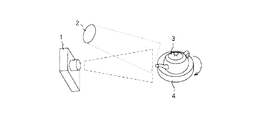
ここで、カメラ1による対象物3の撮影について図3を用いて説明する。本実施形態では、暗室内で回転ステージ4上に載置した対象物3を、面光源2から照射される、対象物3の表面において一定の二次元の広がりを持つ輝度分布を有した照明光で照らし、対象物3にカメラ1を向ける。
【0020】
そして、回転ステージ4を回転させながら、一定の回転角度ごとに複数回撮影し、RGBの3つのカラーバンドからなる画像データを取得する。
【0021】
この際、1回の撮影ごとにカメラ1と対象物3と面光源2の位置(配置)、面光源2(照明光)の輝度、カメラ1の画像特性などの撮影環境情報を記録しておく。
【0022】
こうして対象物3を回転させながら複数回の撮影を行うことにより、対象物3に対する照明方向や観測方向が相対的に変化し、光源方向や視線方向を変えて撮影された複数の画像(画像群)が得られる。
【0023】
なお、本実施形態では、対象物3を回転ステージ4上に載置する場合について説明しているが、対象物を複数の回転軸を持つ装置に設置してもよい。また、本実施形態では、カメラ1および面光源2を固定し、対象物3を回転させる場合について説明しているが、対象物3を固定しておき、カメラ1又は面光源2の位置や方向を変化させながら撮影してもよいし、カメラ1、面光源2および対象物3のうち二者以上の位置を変化させながら撮影してもよい。いずれにせよ、位置の変化や回転により、対象物3に対する光源方向や視線方向が異なる複数の画像を得られるようにすればよい。
【0024】
(撮影環境情報の取得)
撮影環境情報取得部11では、撮影ごとに、面光源2(照明光)の輝度分布に関する情報、カメラ1の特性又は設定に関する情報、カメラ1・対象物3・面光源2の位置や姿勢に関する情報などの撮影環境情報を取得し、彩色情報推定部13に出力する。
【0025】
撮影環境情報の一部は撮影時に記録せず、画像情報から推定してもよい。それには、撮影時に対象物3に固定したマーカーが対象物3と共に画像に写るようにしておく。対象物3上にマーカーの代用となる特徴部分があれば、それをマーカーとして用いてもよい。そして、撮影された画像上のマーカーの位置や色から撮影環境情報を推定し、彩色情報推定部13に出力する。なお、ここでの推定法の例は、佐藤淳著『コンピュータビジョン』(コロナ社,1999)第6章に挙げられている。 (立体形状の取得)
立体形状取得部12では、三次元測定装置5からの実測データに基づいて三次元形状モデルを生成し、彩色情報推定部13に出力するとともに、三次元形状モデルをモデルデータ記憶部14に記録する。
【0026】
なお、三次元形状モデルは、画像撮影時にレンジファインダー等を用いて得てもよいし、画像情報から推定してもよい。或いは工業製品のように形状データが既知であれば、それを用いてもよい。
【0027】
(彩色情報の推定)
彩色情報推定部13では、入力された情報に基づいて彩色情報を推定し、得られた反射定数をモデルデータ記憶部14に記録する。以下、図4のフローチャートを用いて彩色情報の推定法を示す。
【0028】
まず、ステップ(図ではSと略す)1で本フローを開始する。この後、三次元形状モデルの表面の彩色情報を推定する彩色部位(推定部位)ごとに以下の処理を繰り返す。
【0029】
ステップ2では、入力された画像群の全ての画像に対し、各彩色部位における光源中心方向、観測方向および反射強度の対応を計算し、対応表を作成する。これには撮影時のカメラ1、対象物3、面光源2の位置情報およびカメラ1、面光源2の特性又は設定情報から、彩色部位における光源中心方向、観測方向および画像上の位置を算出し、画像上の明度から反射強度を得る。
【0030】
画像上で平面が裏面であったり、他の部位の背後であったり、画像外であったりして反射強度が不明である場合は対応表には入れない。
【0031】
ステップ3では、上記対応表の反射強度を光源中心方向lcと観測方向θoをパラメータとする関数BRDF ’(lc,θo) とみなし(以下、照明光の輝度分布を要素として含む値又は関数にはprime「’」を付けて表す)、照明光の輝度分布を各彩色部位における光源中心方向からの外れ角の関数l(r) で表し、以下の式に基づいてデコンボリュートし、照明方向と観測方向の関数であって2次元の広がりを持たない光の反射率を与える双方向反射分布関数BRDF(θi,θo) に変換する。
【0032】
【数1】

次に、ステップ4では、この双方向反射分布関数BRDFを反射モデル関数と照合する。反射モデルとしては、図5に示した Phongの反射モデルを使用し、上記ステップで得られた対応表中の各彩色部位における光源中心方向、観測方向および反射強度の対応をカラーバンドごとの反射率Rj,Gj,Bj と図12に示す角度変数θj,ρj で表す。
【0034】
なお、図12において、θは彩色部位での法線方向と光源中心方向とのなす角度であり、ρはカメラ1による観測(撮影)方向と光源中心方向との中間のベクトル方向と上記法線とのなす角度である。
【0035】
ここで、添え字jは画像番号(1,2…m)を示す。また、CdR,CdG,CdB は散乱反射定数であり、Cs,nは鏡面反射定数である。そして、誤差ベクトルをεとすると、図10に示す行列式が書ける。彩色部位;lの反射率が不明である場合は、行列式から対応する行を削除する。
【0036】
そして、ステップ5において、誤差ベクトルεを最適な値にする定数の組である(CdR,CdG,CdB,Cs,n)を求め、モデルデータ記憶部14に記録する。最適化には各種の数学的手法を用いることができるが、本発明はこの手法を限定するものではない。
【0037】
例として、最小2乗法を用いる場合には、評価関数を誤差ベクトルεの自己内積ε・εが最小となる組を求める。評価関数は全ての誤差を等価に扱っているが、各値の信頼性を考慮した評価関数を設定してもよい。特に、cosθi,cosθoに比例する重み付けは有効である。
【0038】
以上の処理を全ての彩色部位に対して行う。
【0039】
(CG再現)
このようにしてモデルデータが得られた対象物3をコンピュータグラフィクスで生成表示する際には、コンピュータグラフィクス作成装置7において要求される仮想カメラ、仮想対象物、仮想光源の位置及び向き情報と、仮想カメラおよび仮想光源の特性又は設定情報と、モデルデータ記憶部14に記録された三次元形状モデルとから各彩色部位における照明方向・観測方向・照明照度および生成画像上の表示位置を算出し、照明方向、観測方向およびモデルデータ記憶部14に記録された反射定数を反射モデル関数に代入して反射率を計算する。そして、計算された反射率と照明照度の積を表示色として生成画像上の表示位置に描画する。これにより、任意の照明条件および視線方向での自然な陰影やハイライトが再現される。なお、本実施形態においては、カメラ1、面光源2、回転ステージ4、三次元測定装置5、三次元画像処理装置6およびコンピュータグラフィクス作成装置7を別体のものとして説明したが、これらを単一の装置として構成してもよい。
【0040】
また、本実施形態のように三次元画像処理システムを複数の装置又は機器で構成する場合、装置又は機器間のデータのやり取りは、各種記録媒体や無線・有線のデータ通信手段によって行われる。
【0041】
特に、コンピュータグラフィクス作成装置7を三次元画像処理装置6と別の装置として設けることにより、一度作成されたモデルデータを、複数のコンピュータグラフィクス作成装置で繰り返し利用できるメリットがある。
【0042】
また、本実施形態では、反射モデル関数としてPhong反射モデルを用いる場合について説明したが、本発明では反射モデル関数をこれに限定するものではなく、他の反射モデル関数、例えばTorrance-Sparrowモデルを用いてもよい。つまり、反射率が散乱反射成分と鏡面反射成分の線形和として与えられ、それぞれ複数または1つの定数と角度変数とにより表現されるものであれば本発明に用いることができる。
【0043】
また、本実施形態では、画像がR,G,Bの3色から構成される場合について説明したが、本発明では、単色、他の複数色、スペクトル情報、偏光情報等、対応した反射モデル関数が記述できるものであれば用いることができる。
【0044】
さらに、本実施形態にて説明した彩色情報の推定法では、全ての反射定数が一意に求まるとは限らないが、この場合は、求まらない定数を持つ彩色部位の近傍の彩色部位の反射定数から補完したり、典型的な値で代用したりする等の手法を用いればよい。
【0045】
(第2実施形態)
上記第1実施形態では、反射定数の推定前に実物体の輝度変化を照明光の輝度分布でデコンボリュートする場合について説明したが、輝度分布に依存した輝度分布型反射モデル関数で輝度分布型反射定数を推定した後に反射定数に一定の変換を施すことにより反射定数を推定してもよい。
【0046】
なお、本実施形態の処理を行う三次元画像処理システムの構成も第1実施形態と同じであり、システムを構成する装置および機器には第1実施形態と同符号を付す。
【0047】
以下、三次元画像処理システムでの各処理について説明する。
【0048】
(画像情報の取得)
まず、画像情報取得部10においてカメラ1から画像情報を取得し、彩色情報推定部13に出力する。
【0049】
ここで、カメラ1による対象物3の撮影について図6を用いて説明する。本実施形態では、暗室内で回転ステージ4上に載置した対象物3を、面光源22から照射される、対象物3の表面において一定の二次元の広がりを持つ輝度分布を有し、かつその輝度分布が角度半径σL のガウシアンで近似される広がりを持った照明光で照らし、対象物3にカメラ1を向ける。
【0050】
このような面光源22としては、例えば背後からスポットライトを照射した磨りガラスを用いて構成することができる。
【0051】
そして、回転ステージ4を回転させながら、複数の回転角度で対象物3を撮影し、RGBの3つのカラーバンドからなる画像データを取得する。
【0052】
この際、1回の撮影ごとにカメラ1と対象物3と面光源22の位置(配置)、面光源22(照明光)の輝度、カメラ1の画像特性などの撮影環境情報を記録しておく。
【0053】
こうして対象物3を回転させながら複数回の撮影を行うことにより、対象物3に対する照明方向や観測方向が相対的に変化し、光源方向や視線方向を変えて撮影された複数の画像(画像群)が得られる。
【0054】
なお、本実施形態では、対象物3を回転ステージ4上に載置する場合について説明しているが、対象物を複数の回転軸を持つ装置に設置してもよい。また、本実施形態では、カメラ1および面光源22を固定し、対象物3を回転させる場合について説明しているが、対象物3を固定しておき、カメラ1又は面光源22の位置や方向を変化させながら撮影してもよいし、カメラ1、面光源22および対象物3のうち二者以上の位置を変化させながら撮影してもよい。いずれにせよ、位置の変化や回転により、対象物3に対する光源方向や視線方向が異なる複数の画像を得られるようにすればよい。
【0055】
(撮影環境情報の取得)
撮影環境情報取得部11では、撮影ごとに、面光源22(照明光)の輝度分布に関する情報、カメラ1の特性又は設定に関する情報、カメラ1・対象物3・面光源22の位置や姿勢に関する情報などの撮影環境情報を取得し、彩色情報推定部13に出力する。
【0056】
撮影環境情報の一部は撮影時に記録せず、画像情報から推定してもよい。それには、撮影時に対象物3に固定したマーカーが対象物3と共に画像に写るようにしておく。対象物3上にマーカーの代用となる特徴部分があれば、それをマーカーとして用いてもよい。そして、撮影された画像上のマーカーの位置や色から撮影環境情報を推定し、彩色情報推定部13に出力する。なお、ここでの推定法の例は、第1実施形態にて説明したように、佐藤淳著『コンピュータビジョン』(コロナ社,1999)第6章に挙げられている。
【0057】
(立体形状の取得)
立体形状取得部12では、三次元測定装置5からの実測データに基づいて三次元形状モデルを生成し、彩色情報推定部13に出力するとともに、三次元形状モデルをモデルデータ記憶部14に記録する。
【0058】
なお、三次元形状モデルは、画像撮影時にレンジファインダー等を用いて得てもよいし、画像情報から推定してもよい。或いは工業製品のように形状データが既知であれば、それを用いてもよい。
【0059】
(彩色情報の推定)
彩色情報推定部13では、入力された情報に基づいて彩色情報を推定し、得られた反射定数をモデルデータ記憶部14に記録する。以下、図9のフローチャートを用いて彩色情報の推定法を示す。
【0060】
まず、ステップ(図ではSと略す)21で本フローを開始する。この後、三次元形状モデルの表面の彩色情報を推定する彩色部位(推定部位)ごとに以下の処理を繰り返す。
【0061】
次に、ステップ22で、画像群の全ての画像に対し、各彩色部位における光源中心方向、観測方向、反射強度の対応を計算し、対応表を作成する。これには撮影時のカメラ1、対象物3、面光源22の位置情報およびカメラ1、面光源22の特性又は設定情報から、彩色部位における光源中心方向、観測方向および画像上の位置を算出し、画像上の明度から反射強度を得る。
【0062】
画像上で平面が裏面であったり、他の部位の背後であったり、画像外であったりして反射強度が不明である場合は対応表には入れない。
【0063】
次に、ステップ23では、上記対応表を輝度分布型反射モデル関数と照合する。輝度分布型反射モデルとしては、例えば図7に示す Gaussモデルを使用し、上記ステップで得られた対応表中の各彩色部位における光源中心方向、観測方向および反射強度の対応をカラーバンドごとの反射率Rj,Gj,Bj と図12に示す角度変数θj,ρj で表す。
【0064】
なお、図12において、θは彩色部位での法線方向と光源中心方向とのなす角度であり、ρはカメラ1による観測(撮影)方向と光源中心方向との中間のベクトル方向と上記法線とのなす角度である。
【0065】
また、添え字jは画像番号(1,2…m)を示す。また、CdR,CdG,CdB は錯乱反射定数であり、Cs,σは鏡面反射定数である。そして、誤差ベクトルをεとすると、図11に示す行列式が書ける。彩色部位の反射率が不明である場合は、行列式から対応する行を削除する。
【0066】
そして、ステップ24では、誤差ベクトルεを最適な値にする定数の組である(CdR,CdG,CdB,Cs',σ')を求める。最適化には各種の数学的手法を用いることができるが、本発明はこの手法を限定するものではない。
【0067】
例として、最小2乗法を用いる場合には、評価関数を誤差ベクトルεの自己内積ε・εが最小となる組を求める。評価関数は全ての誤差を等価に扱っているが、各値の信頼性を考慮した評価関数を設定してもよい。
【0068】
次に、ステップ25では、ステップ24で求めた輝度分布型反射定数の組(CdR,CdG,CdB,Cs',σ') を2次元の広がりを持たない照明光を射出する平行(無限遠)光源や点光源等の光源に対する反射定数への変換を行う。
【0069】
反射モデル関数としては図8に示すガウスモデルを用いる。散乱反射成分は照明光の広がりの影響をほとんど受けないものとし、先の(CdR,CdG,CdB)をデータ記録部14に記録する。鏡面反射成分はガウス関数の合成則である
σ’2=σ 2+σL 2
σ2Cs=σ'2Cs'
によりCs(ピーク強度) を求め、(Cs,σ)をデータ記録部14に記録する。
【0070】
なお、σは反射モデル関数の標準偏差、σ’は輝度分布型反射モデル関数の標準偏差、σL は照明光の輝度分布のガウス半径である。
【0071】
以上の処理を全ての彩色部位に対して行う。
【0072】
(CG再現)
このようにしてモデルデータが得られた対象物3をコンピュータグラフィクスで生成表示する際には、コンピュータグラフィクス作成装置7において要求される仮想カメラ、仮想対象物、仮想面光源の位置及び向き情報と、仮想カメラおよび仮想光源の特性又は設定情報と、モデルデータ記憶部14に記録された三次元形状モデルとから各彩色部位における照明方向・観測方向・照明照度および生成画像上の表示位置を算出し、照明方向、観測方向およびモデルデータ記憶部14に記録された反射定数を反射モデル関数に代入して反射率を計算する。そして、計算された反射率と照明照度の積を表示色として生成画像上の表示位置に描画する。これにより、任意の照明条件および視線方向での自然な陰影やハイライトが再現される。
【0073】
なお、本実施形態においては、カメラ1、面光源22、回転ステージ4、三次元計測装置5、三次元画像処理装置6およびコンピュータグラフィクス作成装置7を別体のものとして説明したが、これらを単一の装置として構成してもよい。
【0074】
また、本実施形態のように三次元画像処理システムを複数の装置又は機器で構成する場合、装置又は機器間のデータのやり取りは、各種記録媒体や無線・有線のデータ通信手段によって行われる。
【0075】
特に、コンピュータグラフィクス作成装置7を三次元画像処理装置6と別の装置として設けることにより、一度作成されたモデルデータを、複数のコンピュータグラフィクス作成装置で繰り返し利用できるメリットがある。
【0076】
また、本実施形態では、反射モデル関数としてGaussモデルを用いて説明したが、CG再現時にはPhongモデルが便利な場合がある。GaussモデルとPhongモデルは変換式
σ2=1/(n+5/6)
により、ほぼ対応づけられる。
【0077】
また、これを用いてステップ25で、σに代えてnを記録してもよい。
【0078】
また、本実施形態では、画像がR,G,Bの3色から構成される場合について説明したが、本発明では、単色、他の複数色、スペクトル情報、偏光情報等、対応した反射モデル関数が記述できるものであれば用いることができる。
【0079】
さらに、本実施形態にて説明した彩色情報の推定法では、全ての反射定数が一意に求まるとは限らないが、この場合は、求まらない定数を持つ彩色部位の近傍の彩色部位の反射定数から補完したり、典型的な値で代用したりする等の手法を用いればよい。
【0080】
【発明の効果】
以上説明したように、本発明によれば、実物体をその表面から見て2次元の広がりを持つ輝度分布を有する照明光で照明するようにしたので、鏡面反射をより広い角度範囲で観測できる。このため、比較的少数の撮影画像によって、鏡面反射が鋭い場合における表面属性の推定部位(彩色部位)での鏡面反射の観測漏れを防止し、正しい表面属性を推定することができる。
【0081】
したがって、本発明を用いて実物体の表面属性を推定すれば、任意の照明条件および視線方向での自然な陰影やハイライトが再現された三次元画像を作成することができる。
【図面の簡単な説明】
【図1】本発明の第1実施形態である三次元画像処理システムの構成図である。
【図2】上記第1実施形態の三次元画像処理システムを構成する三次元画像処理装置の構成を示すブロック図である。
【図3】上記第1実施形態の三次元画像処理システムにおける実物体の画像情報取得の例を示す図である。
【図4】上記第1実施形態の三次元画像処理装置における彩色情報の推定処理を示すフローチャートである。
【図5】 Phong反射モデルの式である。
【図6】本発明の第2実施形態である三次元画像処理システムにおける実物体の画像情報取得の例を示す図である。
【図7】輝度分布型Gauss反射モデルの式である。
【図8】 Gauss反射モデルの式である。
【図9】上記第2実施形態の三次元画像処理装置における彩色情報の推定処理を示すフローチャートである。
【図10】上記第1実施形態においてPhong反射モデルを適用した際の行列式である。
【図11】上記第2実施形態においてPhong反射モデルを適用した際の行列式である。
【図12】θ、ρの説明図である
【符号の説明】
1 デジタルカメラ
2,22 面光源
3 対象物
4 回転ステージ
5 三次元測定装置
6 三次元画像処理装置
7 コンピュータグラフィクス生成装置[0001]
BACKGROUND OF THE INVENTION
The present invention relates to a three-dimensional image processing method and apparatus for generating surface attribute data necessary for forming a three-dimensional image of an actual object (real object).
[0002]
[Prior art]
When reproducing a real object as a three-dimensional image by computer graphics, there is a method of pasting an image obtained by photographing a real object with a camera to each part of a three-dimensional shape model as proposed in Japanese Patent Laid-Open No. 2000-348213. . In such a method, in order to be able to observe a three-dimensional image from various viewpoints, a plurality of images taken from a plurality of directions are prepared, and an appropriate image is selected for the viewpoint during reproduction. Pasted on the 3D shape model.
[0003]
However, with such a method, the real object reproduced as a three-dimensional image cannot be brought into an illumination state different from that at the time of photographing. In addition, since the camera image originally includes shadows and highlights, an unnatural image is obtained if an additional shadow or highlight is added to the object to which the camera image is pasted.
[0004]
Therefore, as described in SIGRAPH Computer Graphics Proceedings, Annual Conference Seriec, 1997, p379-387 "Object Shape and Reflectance Modeling from Observation" It is expressed by a bidirectional reflection distribution function BRDF (Bi-directional Reflectance Distribution Function), and a method of introducing a function model into BRDF and expressing it by a reflection constant is adopted.
[0005]
In this method, the reflection characteristics of the chromatic parts placed on the surface of the three-dimensional shape model are retained as reflection constants, and the constants are substituted into the reflection model function during reproduction to calculate arbitrary lighting conditions with relatively small coloring information.・ Natural shadows and highlights in the line of sight can be reproduced.
[0006]
As represented by the Phong reflection model, many reflection models consider light reflection as a linear sum of a scattered (diffuse) reflection component and a specular reflection component, and are each represented by a plurality of parameters.
[0007]
[Problems to be solved by the invention]
The reflection constant is estimated for each colored region using a plurality of pieces of image information captured by changing the light source direction or the line of sight (observation, imaging) direction. Also, since BRDF is a function of the illumination direction and the observation direction with illumination light that does not have a two-dimensional spread, a light source that can be approximated to a part light source or a parallel (infinite) light source is used.
[0008]
However, an object that exhibits specular reflection only in a very narrow angle range, such as a metallic luster, has a colored portion in which no specular reflection is observed in the plurality of image information. In this case, specular reflection is not observed in the colored portion. There is a possibility that it is erroneously estimated to be absent.
[0009]
In order to avoid this, it is necessary to shoot at an angle interval smaller than the specular reflection spread at the time of image shooting, but there is a problem that the processing of image information and the time and effort of shooting become enormous.
[0010]
[Means for Solving the Problems]
In order to solve the above-described problem, in the three-dimensional image processing method and apparatus of the present invention, photographing a real object irradiated with illumination light from a light source having a luminance distribution having a two-dimensional spread when viewed from the surface of the real object. Image information is acquired, and this photographed image information and photographing environment information at the time of photographing (information on the luminance distribution of the light source, information on characteristics or settings of the photographing device for photographing, information on the position and orientation of the real object, the light source, and the photographing device) Etc.), the surface attribute (especially the reflection characteristic) of the real object is estimated.In the three-dimensional image processing method and apparatus according to the first invention of the present application, the bidirectional attribute that gives the reflectance of the estimated surface attribute of the real object by the light source that does not have a two-dimensional spread at each part of the surface of the real object. It is represented by a reflection distribution function. In the three-dimensional image processing method and apparatus according to the second invention of the present application, a luminance distribution type bidirectional reflection distribution function depending on the luminance distribution of illumination light is estimated, and thereafter the luminance distribution type bidirectional reflection distribution function is actually used. It is converted into a bidirectional reflection distribution function that gives the reflectance by a light source that does not have a two-dimensional spread at each part of the body surface.
[0011]
In this way, when the real object is illuminated with illumination light having a luminance distribution having a two-dimensional spread when viewed from the surface, specular reflection is observed in a wider angular range. For this reason, it is possible to prevent omission of observation of specular reflection at a surface attribute estimation portion (colored portion) when the specular reflection is sharp, and to estimate a correct surface attribute with a relatively small number of captured images.
[0012]
Note that when the bidirectional reflection distribution function BRDF is estimated at each estimation site, this bidirectional reflection distribution function BRDF is defined for light irradiated from one direction that does not have a two-dimensional spread. In the invention, the bidirectional reflection distribution function BRDF is estimated by deconvoluting the luminance change of the real object obtained based on the captured image information with the luminance distribution of the illumination light.
[0013]
DETAILED DESCRIPTION OF THE INVENTION
(First embodiment)
FIG. 1 shows a configuration of a three-dimensional image processing system according to the first embodiment of the present invention. In this embodiment, the luminance change of the real object is deconvoluted with the luminance distribution of the illumination light before the reflection constant is estimated, and the phong function is obtained from the bidirectional reflection distribution function BRDF.
[0014]
The three-dimensional image processing system of the present embodiment includes a digital camera (imaging device) 1 that photographs an
[0015]
The three-dimensional shape model generated by the three-dimensional
[0016]
Each of the three-dimensional measuring device 5 and the
[0017]
Next, each process in the three-dimensional image processing system will be described with reference to FIG. FIG. 2 shows the configuration within the three-dimensional
[0018]
(Acquisition of image information)
First, the image
[0019]
Here, photographing of the
[0020]
Then, while rotating the rotary stage 4, the image is taken a plurality of times at a certain rotation angle, and image data including three color bands of RGB is acquired.
[0021]
At this time, shooting environment information such as the position (arrangement) of the
[0022]
By performing multiple shootings while rotating the
[0023]
In the present embodiment, the case where the
[0024]
(Acquisition of shooting environment information)
photographenvironmentThe information acquisition unit 11 includes information on the luminance distribution of the surface light source 2 (illumination light), information on the characteristics or settings of the
[0025]
A part of the shooting environment information may not be recorded at the time of shooting but may be estimated from the image information. For this purpose, a marker fixed to the
The three-dimensional
[0026]
Note that the three-dimensional shape model may be obtained using a range finder or the like at the time of image shooting, or may be estimated from image information. Alternatively, if the shape data is known like an industrial product, it may be used.
[0027]
(Estimation of coloring information)
The coloring
[0028]
First, in step (abbreviated as S in the figure) 1, this flow is started. Thereafter, the following processing is repeated for each coloring part (estimated part) for estimating the coloring information of the surface of the three-dimensional shape model.
[0029]
In
[0030]
If the reflection intensity is unknown because the plane on the image is the back surface, behind another part, or outside the image, it is not included in the correspondence table.
[0031]
In
[0032]
[Expression 1]
Next, in step 4, this bidirectional reflection distribution function BRDF is collated with the reflection model function. As the reflection model, the Phong reflection model shown in FIG. 5 is used, and the correspondence between the light source center direction, the observation direction, and the reflection intensity at each colored portion in the correspondence table obtained in the above step is the reflectance for each color band. Rj, Gj, Bj And the angle variable θ shown in FIG.j, Ρj Represented by
[0034]
In FIG. 12, θ is an angle formed by the normal direction at the colored portion and the light source center direction, and ρ is a vector direction intermediate between the observation (imaging) direction of the
[0035]
Here, the subscript j indicates the image number (1, 2,... M). CdR, CdG, CdB Is the scattering reflection constant, and Cs, n is the specular reflection constant. When the error vector is ε, the determinant shown in FIG. 10 can be written. If the reflectance of the colored portion; l is unknown, the corresponding row is deleted from the determinant.
[0036]
Then, in step 5, a set of constants that optimize the error vector ε (CdR, CdG, CdB, Cs, n) is obtained and recorded in the model data storage unit 14. Various mathematical methods can be used for optimization, but the present invention is not limited to this method.
[0037]
For example, when the least square method is used, the evaluation function is obtained as a pair that minimizes the self-product ε · ε of the error vector ε. Although the evaluation function treats all errors equally, an evaluation function that considers the reliability of each value may be set. In particular, weighting proportional to cos θi and cos θo is effective.
[0038]
The above processing is performed for all the colored portions.
[0039]
(CG reproduction)
When the
[0040]
When the 3D image processing system is configured by a plurality of devices or devices as in the present embodiment, data exchange between the devices or devices is performed by various recording media and wireless / wired data communication means.
[0041]
In particular, by providing the computer graphics creation device 7 as a separate device from the three-dimensional
[0042]
In this embodiment, the case where the Phong reflection model is used as the reflection model function has been described. However, in the present invention, the reflection model function is not limited to this, and another reflection model function such as a Torrance-Sparrow model is used. May be. That is, any reflectance can be used in the present invention as long as the reflectance is given as a linear sum of a scattered reflection component and a specular reflection component and each is expressed by a plurality or one constant and an angle variable.
[0043]
In this embodiment, the case where the image is composed of three colors of R, G, and B has been described. However, in the present invention, a corresponding reflection model function such as a single color, other multiple colors, spectrum information, polarization information, or the like is supported. Can be used as long as it can be described.
[0044]
Furthermore, in the coloring information estimation method described in the present embodiment, not all reflection constants are uniquely obtained. In this case, however, the reflection of a colored portion in the vicinity of a colored portion having a constant that cannot be obtained. A method such as complementing from a constant or substituting with a typical value may be used.
[0045]
(Second Embodiment)
In the first embodiment, the case where the luminance change of the real object is deconvoluted with the luminance distribution of the illumination light before the reflection constant is estimated has been described, but the luminance distribution type reflection model function depending on the luminance distribution is used. The reflection constant may be estimated by performing a certain conversion on the reflection constant after estimating the constant.
[0046]
Note that the configuration of the three-dimensional image processing system that performs the processing of the present embodiment is the same as that of the first embodiment, and devices and devices that constitute the system are denoted by the same reference numerals as those of the first embodiment.
[0047]
Hereinafter, each process in the three-dimensional image processing system will be described.
[0048]
(Acquisition of image information)
First, the image
[0049]
Here, photographing of the
[0050]
As such a
[0051]
Then, while rotating the rotary stage 4, the
[0052]
At this time, the shooting environment information such as the position (arrangement) of the
[0053]
By performing multiple shootings while rotating the
[0054]
In the present embodiment, the case where the
[0055]
(Acquisition of shooting environment information)
photographenvironmentThe information acquisition unit 11 includes information on the luminance distribution of the surface light source 22 (illumination light), information on the characteristics or settings of the
[0056]
A part of the shooting environment information may not be recorded at the time of shooting but may be estimated from the image information. For this purpose, a marker fixed to the
[0057]
(Acquire 3D shape)
The three-dimensional
[0058]
Note that the three-dimensional shape model may be obtained using a range finder or the like at the time of image shooting, or may be estimated from image information. Alternatively, if the shape data is known like an industrial product, it may be used.
[0059]
(Estimation of coloring information)
The coloring
[0060]
First, in step (abbreviated as S in the figure) 21, this flow is started. Thereafter, the following processing is repeated for each coloring part (estimated part) for estimating the coloring information of the surface of the three-dimensional shape model.
[0061]
Next, in
[0062]
If the reflection intensity is unknown because the plane on the image is the back surface, behind another part, or outside the image, it is not included in the correspondence table.
[0063]
Next, in step 23, the correspondence table is collated with a luminance distribution type reflection model function. As the luminance distribution type reflection model, for example, the Gauss model shown in FIG. 7 is used, and the correspondence between the light source center direction, the observation direction, and the reflection intensity in each coloring portion in the correspondence table obtained in the above step is reflected for each color band. Rate Rj, Gj, Bj And the angle variable θ shown in FIG.j, Ρj Represented by
[0064]
In FIG. 12, θ isColoringThe angle between the normal direction at the part and the light source center direction, and ρ is the angle between the vector direction intermediate between the observation (imaging) direction of the
[0065]
The subscript j indicates the image number (1, 2,... M). CdR, CdG, CdB Is a confusion reflection constant, and Cs, σ is a specular reflection constant. If the error vector is ε, the determinant shown in FIG. 11 can be written. If the reflectance of the colored portion is unknown, the corresponding row is deleted from the determinant.
[0066]
Then, in step 24, a set of constants that optimize the error vector ε (CdR, CdG, CdB, Cs ′, σ ′). Various mathematical methods can be used for optimization, but the present invention is not limited to this method.
[0067]
For example, when the least square method is used, the evaluation function is obtained as a pair that minimizes the self-product ε · ε of the error vector ε. Although the evaluation function treats all errors equally, an evaluation function that considers the reliability of each value may be set.
[0068]
Next, in step 25, the set of luminance distribution type reflection constants obtained in step 24 (CdR, CdG, CdB, Cs ′, σ ′) is converted into a reflection constant for a light source such as a parallel (infinity) light source or a point light source that emits illumination light having no two-dimensional spread.
[0069]
A Gaussian model shown in FIG. 8 is used as the reflection model function. The diffuse reflection component is hardly affected by the spread of the illumination light, and the previous (CdR, CdG, CdB) Is recorded in the data recording unit 14. Specular reflection component is a Gaussian composition rule
σ ’2=σ 2+ σL 2
σ2Cs = σ '2Cs'
To obtain Cs (peak intensity) and record (Cs, σ) in the data recording unit 14.
[0070]
Σ is the standard deviation of the reflection model function, σ ′ is the standard deviation of the luminance distribution type reflection model function, and σLIs the Gaussian radius of the luminance distribution of the illumination light.
[0071]
The above processing is performed for all the colored portions.
[0072]
(CG reproduction)
When the
[0073]
In the present embodiment, the
[0074]
When the 3D image processing system is configured by a plurality of devices or devices as in the present embodiment, data exchange between the devices or devices is performed by various recording media and wireless / wired data communication means.
[0075]
In particular, by providing the computer graphics creation device 7 as a separate device from the three-dimensional
[0076]
In the present embodiment, the Gauss model is used as the reflection model function. However, the Phong model may be useful during CG reproduction. Gauss model and Phong model are converted
σ2= 1 / (n + 5/6)
Is almost matched.
[0077]
Also use this to step25Thus, n may be recorded instead of σ.
[0078]
In this embodiment, the case where the image is composed of three colors of R, G, and B has been described. However, in the present invention, a corresponding reflection model function such as a single color, other multiple colors, spectrum information, polarization information, or the like is supported. Can be used as long as it can be described.
[0079]
Furthermore, in the coloring information estimation method described in the present embodiment, not all reflection constants are uniquely obtained. In this case, however, the reflection of a colored portion in the vicinity of a colored portion having a constant that cannot be obtained. A method such as complementing from a constant or substituting with a typical value may be used.
[0080]
【The invention's effect】
As described above, according to the present invention, since a real object is illuminated with illumination light having a luminance distribution having a two-dimensional spread when viewed from the surface, specular reflection can be observed in a wider angle range. . For this reason, it is possible to prevent the observation of specular reflection from being missed at the estimated part (colored part) of the surface attribute when the specular reflection is sharp, and to estimate the correct surface attribute with a relatively small number of captured images.
[0081]
Therefore, if the surface attribute of a real object is estimated using the present invention, a three-dimensional image in which natural shadows and highlights in an arbitrary illumination condition and line-of-sight direction are reproduced can be created.
[Brief description of the drawings]
FIG. 1 is a configuration diagram of a three-dimensional image processing system according to a first embodiment of the present invention.
FIG. 2 is a block diagram showing a configuration of a three-dimensional image processing apparatus constituting the three-dimensional image processing system of the first embodiment.
FIG. 3 is a diagram illustrating an example of acquisition of image information of a real object in the three-dimensional image processing system according to the first embodiment.
FIG. 4 is a flowchart showing color information estimation processing in the three-dimensional image processing apparatus according to the first embodiment;
FIG. 5 is an expression of a Phong reflection model.
FIG. 6 is a diagram showing an example of acquisition of real object image information in the three-dimensional image processing system according to the second embodiment of the present invention;
FIG. 7 is a formula of a luminance distribution type Gaussian reflection model.
FIG. 8 is an expression of a Gaussian reflection model.
FIG. 9 is a flowchart showing color information estimation processing in the 3D image processing apparatus according to the second embodiment;
FIG. 10 is a determinant when the Phong reflection model is applied in the first embodiment.
FIG. 11 is a determinant when the Phong reflection model is applied in the second embodiment.
FIG. 12 is an explanatory diagram of θ and ρ.
[Explanation of symbols]
1 Digital camera
2,22 Surface light source
3 objects
4 Rotating stage
5 CMM
6 Three-dimensional image processing device
7 Computer graphics generator
Claims (16)
この画像情報取得手段により取得した撮影画像情報と撮影時の撮影環境情報とに基づいて前記実物体の表面属性を推定する表面属性推定手段とを有し、
前記表面属性推定手段において推定される前記実物体の表面属性は、前記実物体の表面の各部における2次元の広がりを持たない光源による反射率を与える双方向反射分布関数で表されることを特徴とする三次元画像処理装置。 Image information acquisition means for acquiring captured image information of the real object irradiated with illumination light from a light source having a luminance distribution having a two-dimensional spread when viewed from the surface of the real object;
Surface attribute estimation means for estimating the surface attribute of the real object based on the captured image information acquired by the image information acquisition means and the shooting environment information at the time of shooting,
The surface attribute of the real object estimated by the surface attribute estimation means is represented by a bidirectional reflection distribution function that gives a reflectance by a light source having no two-dimensional extent in each part of the surface of the real object. A three-dimensional image processing apparatus.
前記反射定数は、散乱反射成分に関する散乱反射定数と、鏡面反射成分に関する鏡面反射定数とを含むことを特徴とする請求項3に記載の三次元画像処理装置。The reflection model function is represented by a function in which a scattered reflection component and a specular reflection component are linearly combined,
The three-dimensional image processing apparatus according to claim 3 , wherein the reflection constant includes a scattering reflection constant related to a scattering reflection component and a specular reflection constant related to a specular reflection component.
この画像情報取得手段により取得した撮影画像情報と撮影時の撮影環境情報とに基づいて前記実物体の表面属性を推定する表面属性推定手段とを有し、
前記表面属性推定手段は、前記照明光の輝度分布に依存した輝度分布型双方向反射分布関数を推定し、その後、輝度分布型双方向反射分布関数を前記実物体の表面の各部における2次元の広がりを持たない光源による反射率を与える双方向反射分布関数に変換することを特徴とする三次元画像処理装置。 Image information acquisition means for acquiring captured image information of the real object irradiated with illumination light from a light source having a luminance distribution having a two-dimensional spread when viewed from the surface of the real object;
Surface attribute estimation means for estimating the surface attribute of the real object based on the captured image information acquired by the image information acquisition means and the shooting environment information at the time of shooting,
The surface attribute estimation unit estimates a luminance distribution type bidirectional reflection distribution function depending on the luminance distribution of the illumination light, and then calculates the two-dimensional luminance distribution type bidirectional reflection distribution function in each part of the surface of the real object. A three-dimensional image processing apparatus, wherein the image is converted into a bidirectional reflection distribution function that gives a reflectance by a light source having no spread.
前記表面属性推定手段は、前記撮影画像情報と前記撮影環境情報とに基づいて前記輝度分布型反射定数を推定することを特徴とする請求項5に記載の三次元画像処理装置。The luminance distribution-type bidirectional reflectance distribution function, is the table in the luminance distribution type reflection model function that depends on the luminance distribution of the illumination light, the brightness distribution type reflection model function, a plurality of luminance distribution type reflection constant as a function element Including
6. The three-dimensional image processing apparatus according to claim 5 , wherein the surface attribute estimation unit estimates the luminance distribution type reflection constant based on the photographed image information and the photographing environment information.
前記輝度分布型反射定数は、散乱反射成分に関する散乱反射定数と、鏡面反射成分に関する鏡面反射定数とを含むことを特徴とする請求項6に記載の三次元画像処理装置。The luminance distribution type reflection model function is represented by a function in which a scattered reflection component and a specular reflection component are linearly combined,
The three-dimensional image processing apparatus according to claim 6 , wherein the luminance distribution type reflection constant includes a scattering reflection constant relating to a scattering reflection component and a specular reflection constant relating to a specular reflection component.
前記鏡面反射定数として少なくともピーク強度と標準偏差を持つことを特徴とする請求項9に記載の三次元画像処理装置。The specular reflection component of the luminance distribution type reflection model function is a Gaussian function,
The three-dimensional image processing apparatus according to claim 9 , wherein the specular reflection constant has at least a peak intensity and a standard deviation.
実物体の表面から見て2次元の広がりを持つ輝度分布を有する光源から照明光が照射された前記実物体の撮影画像情報を取得する第1のステップと、
この第1のステップで取得した撮影画像情報と撮影時の撮影環境情報とに基づいて前記実物体の表面属性を推定する第2のステップとを有し、
前記第2のステップにおいて推定される前記実物体の表面属性は、前記実物体の表面の各部における2次元の広がりを持たない光源による反射率を与える双方向反射分布関数で表されることを特徴とする三次元画像処理プログラム。A program that runs on a computer,
A first step of acquiring photographed image information of the real object irradiated with illumination light from a light source having a luminance distribution having a two-dimensional spread when viewed from the surface of the real object;
Have a second step of estimating a surface attributes of the real object based on the imaging environment information at the time of photographing the photographed image information obtained by this first step,
The surface attribute of the real object estimated in the second step is represented by a bidirectional reflection distribution function that gives a reflectance by a light source having no two-dimensional extent in each part of the surface of the real object. A three-dimensional image processing program.
実物体の表面から見て2次元の広がりを持つ輝度分布を有する光源から照明光が照射された前記実物体の撮影画像情報を取得する第1のステップと、A first step of acquiring photographed image information of the real object irradiated with illumination light from a light source having a luminance distribution having a two-dimensional spread when viewed from the surface of the real object;
この第1のステップで取得した撮影画像情報と撮影時の撮影環境情報とに基づいて前記実物体の表面属性を推定する第2のステップとを有し、A second step of estimating the surface attribute of the real object based on the photographed image information acquired in the first step and the photographing environment information at the time of photographing;
前記第2のステップにおいて、前記照明光の輝度分布に依存した輝度分布型双方向反射分布関数を推定し、その後、輝度分布型双方向反射分布関数を前記実物体の表面の各部における2次元の広がりを持たない光源による反射率を与える双方向反射分布関数に変換することを特徴とする三次元画像処理プログラム。In the second step, a luminance distribution type bidirectional reflection distribution function depending on the luminance distribution of the illumination light is estimated, and thereafter the luminance distribution type bidirectional reflection distribution function is calculated in a two-dimensional manner at each part of the surface of the real object. A three-dimensional image processing program that converts to a bidirectional reflection distribution function that gives the reflectance of a light source having no spread.
この第1のステップで取得した撮影画像情報と撮影時の撮影環境情報とに基づいて前記実物体の表面属性を推定する第2のステップとを有し、
前記第2のステップにおいて推定される前記実物体の表面属性は、前記実物体の表面の各部における2次元の広がりを持たない光源による反射率を与える双方向反射分布関数で表されることを特徴とする三次元画像処理方法。A first step of acquiring photographed image information of the real object irradiated with illumination light from a light source having a luminance distribution having a two-dimensional spread when viewed from the surface of the real object;
Have a second step of estimating a surface attributes of the real object based on the imaging environment information at the time of photographing the photographed image information obtained by this first step,
The surface attribute of the real object estimated in the second step is represented by a bidirectional reflection distribution function that gives a reflectance by a light source having no two-dimensional extent in each part of the surface of the real object. A three-dimensional image processing method.
この第1のステップで取得した撮影画像情報と撮影時の撮影環境情報とに基づいて前記実物体の表面属性を推定する第2のステップとを有し、A second step of estimating the surface attribute of the real object based on the photographed image information acquired in the first step and the photographing environment information at the time of photographing;
前記第2のステップにおいて、前記照明光の輝度分布に依存した輝度分布型双方向反射分布関数を推定し、その後、輝度分布型双方向反射分布関数を前記実物体の表面の各部における2次元の広がりを持たない光源による反射率を与える双方向反射分布関数に変換することを特徴とする三次元画像処理方法。In the second step, a luminance distribution type bidirectional reflection distribution function depending on the luminance distribution of the illumination light is estimated, and thereafter the luminance distribution type bidirectional reflection distribution function is calculated in a two-dimensional manner at each part of the surface of the real object. A three-dimensional image processing method characterized by converting to a bidirectional reflection distribution function that gives reflectance by a light source having no spread.
Priority Applications (2)
| Application Number | Priority Date | Filing Date | Title |
|---|---|---|---|
| JP2002000927A JP3962588B2 (en) | 2002-01-07 | 2002-01-07 | 3D image processing method, 3D image processing apparatus, 3D image processing system, and 3D image processing program |
| US10/321,461 US7200262B2 (en) | 2002-01-07 | 2002-12-18 | 3-dimensional image processing method, 3-dimensional image processing device, and 3-dimensional image processing system |
Applications Claiming Priority (1)
| Application Number | Priority Date | Filing Date | Title |
|---|---|---|---|
| JP2002000927A JP3962588B2 (en) | 2002-01-07 | 2002-01-07 | 3D image processing method, 3D image processing apparatus, 3D image processing system, and 3D image processing program |
Publications (3)
| Publication Number | Publication Date |
|---|---|
| JP2003203220A JP2003203220A (en) | 2003-07-18 |
| JP2003203220A5 JP2003203220A5 (en) | 2005-06-23 |
| JP3962588B2 true JP3962588B2 (en) | 2007-08-22 |
Family
ID=19190561
Family Applications (1)
| Application Number | Title | Priority Date | Filing Date |
|---|---|---|---|
| JP2002000927A Expired - Lifetime JP3962588B2 (en) | 2002-01-07 | 2002-01-07 | 3D image processing method, 3D image processing apparatus, 3D image processing system, and 3D image processing program |
Country Status (2)
| Country | Link |
|---|---|
| US (1) | US7200262B2 (en) |
| JP (1) | JP3962588B2 (en) |
Families Citing this family (41)
| Publication number | Priority date | Publication date | Assignee | Title |
|---|---|---|---|---|
| JP2004252603A (en) * | 2003-02-18 | 2004-09-09 | Canon Inc | Three-dimensional data processing method |
| US7091973B1 (en) * | 2003-06-20 | 2006-08-15 | Jonathan Michael Cohen | Apparatus and method for estimating reflected radiance under complex distant illumination |
| DE102006047777A1 (en) * | 2006-03-17 | 2007-09-20 | Daimlerchrysler Ag | Virtual spotlight for marking objects of interest in image data |
| JP4888023B2 (en) * | 2006-10-02 | 2012-02-29 | 大日本印刷株式会社 | Method and apparatus for creating reflection characteristic data of object |
| US9767599B2 (en) * | 2006-12-29 | 2017-09-19 | X-Rite Inc. | Surface appearance simulation |
| US8218903B2 (en) * | 2007-04-24 | 2012-07-10 | Sony Computer Entertainment Inc. | 3D object scanning using video camera and TV monitor |
| WO2009019887A1 (en) * | 2007-08-07 | 2009-02-12 | Panasonic Corporation | Image processing device and image processing method |
| DE102007054906B4 (en) * | 2007-11-15 | 2011-07-28 | Sirona Dental Systems GmbH, 64625 | Method for optical measurement of the three-dimensional geometry of objects |
| US8217961B2 (en) * | 2009-03-27 | 2012-07-10 | Mitsubishi Electric Research Laboratories, Inc. | Method for estimating 3D pose of specular objects |
| JP5441752B2 (en) * | 2009-03-31 | 2014-03-12 | ミツビシ・エレクトリック・リサーチ・ラボラトリーズ・インコーポレイテッド | Method and apparatus for estimating a 3D pose of a 3D object in an environment |
| US9098945B2 (en) * | 2009-05-01 | 2015-08-04 | Microsoft Technology Licensing, Llc | Modeling anisotropic surface reflectance with microfacet synthesis |
| US8803880B2 (en) * | 2009-08-21 | 2014-08-12 | Peking University | Image-based lighting simulation for objects |
| WO2012000847A2 (en) * | 2010-07-01 | 2012-01-05 | Thomson Licensing | Method of estimating diffusion of light |
| US9473700B2 (en) | 2010-11-03 | 2016-10-18 | The Trustees Of Columbia University In The City Of New York | Camera systems and methods for gigapixel computational imaging |
| US10796494B2 (en) | 2011-06-06 | 2020-10-06 | Microsoft Technology Licensing, Llc | Adding attributes to virtual representations of real-world objects |
| US8933990B2 (en) | 2011-08-15 | 2015-01-13 | Joshua Sophrin | Method for 3D visual mapping using 3D stereoscopic video content |
| US9163938B2 (en) * | 2012-07-20 | 2015-10-20 | Google Inc. | Systems and methods for image acquisition |
| US9117267B2 (en) | 2012-10-18 | 2015-08-25 | Google Inc. | Systems and methods for marking images for three-dimensional image generation |
| TWI512642B (en) * | 2013-01-25 | 2015-12-11 | Delta Electronics Inc | Method of fast image matching |
| JP6126437B2 (en) | 2013-03-29 | 2017-05-10 | キヤノン株式会社 | Image processing apparatus and image processing method |
| JP6231855B2 (en) * | 2013-11-08 | 2017-11-15 | キヤノン株式会社 | Image processing apparatus and image processing method |
| JP6338369B2 (en) * | 2013-12-26 | 2018-06-06 | キヤノン株式会社 | Information processing apparatus and information processing method |
| JP6367624B2 (en) * | 2014-07-07 | 2018-08-01 | 株式会社スクウェア・エニックス | Program, information processing apparatus, calculation method, and recording medium |
| EP3057067B1 (en) * | 2015-02-16 | 2017-08-23 | Thomson Licensing | Device and method for estimating a glossy part of radiation |
| CN106650634B (en) * | 2015-04-11 | 2020-04-24 | 苏州思源科安信息技术有限公司 | Image mirror reflection interference detection and feedback method for terminal biological recognition |
| US20170188010A1 (en) * | 2015-12-29 | 2017-06-29 | Canon Kabushiki Kaisha | Reconstruction of local curvature and surface shape for specular objects |
| US9996981B1 (en) * | 2016-03-07 | 2018-06-12 | Bao Tran | Augmented reality system |
| WO2017180615A1 (en) * | 2016-04-12 | 2017-10-19 | Quidient, Llc | Quotidian scene reconstruction engine |
| JP6650848B2 (en) * | 2016-08-22 | 2020-02-19 | 株式会社ソニー・インタラクティブエンタテインメント | Information processing apparatus, information processing system, and information processing method |
| JP6812271B2 (en) | 2017-02-27 | 2021-01-13 | キヤノン株式会社 | Image processing equipment, image processing methods and programs |
| CN108537841B (en) * | 2017-03-03 | 2021-10-08 | 株式会社理光 | Robot picking method and device and electronic equipment |
| US10922878B2 (en) * | 2017-10-04 | 2021-02-16 | Google Llc | Lighting for inserted content |
| JP6560726B2 (en) * | 2017-10-20 | 2019-08-14 | キヤノン株式会社 | Image processing apparatus and image processing method |
| CN112470191B (en) | 2018-05-02 | 2024-10-01 | 奎蒂安特有限公司 | Codec for processing scenes with almost infinite detail |
| EP3824621A4 (en) | 2018-07-19 | 2022-04-27 | Activ Surgical, Inc. | Systems and methods for multi-modal sensing of depth in vision systems for automated surgical robots |
| JP6800938B2 (en) | 2018-10-30 | 2020-12-16 | キヤノン株式会社 | Image processing equipment, image processing methods and programs |
| CA3132350A1 (en) | 2019-04-08 | 2020-10-15 | Stephen Tully | Systems and methods for medical imaging |
| CN114599263A (en) | 2019-08-21 | 2022-06-07 | 艾科缇弗外科公司 | System and method for medical imaging |
| JP2021056164A (en) * | 2019-10-01 | 2021-04-08 | 富士ゼロックス株式会社 | Information processing device, light emission device, information processing system, and program |
| JP7463697B2 (en) * | 2019-11-01 | 2024-04-09 | Toppanホールディングス株式会社 | Gloss acquisition state calculation device, gloss acquisition state calculation method, gloss acquisition state calculation program, terminal, and gloss acquisition state display program |
| CN114322842B (en) * | 2021-12-09 | 2023-08-18 | 中国石油大学(华东) | High-reflection part measurement method and system based on improved Phong model |
Family Cites Families (4)
| Publication number | Priority date | Publication date | Assignee | Title |
|---|---|---|---|---|
| US6654013B1 (en) * | 2000-03-17 | 2003-11-25 | Hewlett-Packard Development Company, Lp. | Apparatus for and method of enhancing shape perception with parametric texture maps |
| US6765573B2 (en) * | 2000-10-26 | 2004-07-20 | Square Enix Co., Ltd. | Surface shading using stored texture map based on bidirectional reflectance distribution function |
| US7106325B2 (en) * | 2001-08-03 | 2006-09-12 | Hewlett-Packard Development Company, L.P. | System and method for rendering digital images having surface reflectance properties |
| US6677956B2 (en) * | 2001-08-15 | 2004-01-13 | Mitsubishi Electric Research Laboratories, Inc. | Method for cross-fading intensities of multiple images of a scene for seamless reconstruction |
-
2002
- 2002-01-07 JP JP2002000927A patent/JP3962588B2/en not_active Expired - Lifetime
- 2002-12-18 US US10/321,461 patent/US7200262B2/en active Active
Also Published As
| Publication number | Publication date |
|---|---|
| JP2003203220A (en) | 2003-07-18 |
| US20030128207A1 (en) | 2003-07-10 |
| US7200262B2 (en) | 2007-04-03 |
Similar Documents
| Publication | Publication Date | Title |
|---|---|---|
| JP3962588B2 (en) | 3D image processing method, 3D image processing apparatus, 3D image processing system, and 3D image processing program | |
| Gardner et al. | Deep parametric indoor lighting estimation | |
| US20230154105A1 (en) | System and method for three-dimensional scanning and for capturing a bidirectional reflectance distribution function | |
| Unger et al. | Capturing and Rendering with Incident Light Fields. | |
| Marschner | Inverse rendering for computer graphics | |
| CN104952063B (en) | For indicating the method and system of virtual objects in the view of true environment | |
| US6930685B1 (en) | Image processing method and apparatus | |
| US7113633B2 (en) | System and method for discovering and categorizing attributes of a digital image | |
| JP2018514237A (en) | Texture mapping apparatus and method for dental 3D scanner | |
| Brostow et al. | Video normals from colored lights | |
| JP2003202216A (en) | Method, device, system and program for three-dimensional image processing | |
| CN109565577A (en) | Colour correcting apparatus, color calibration system, colour correction hologram, color correcting method and program | |
| Kitanovski et al. | Objective evaluation of relighting models on translucent materials from multispectral RTI images | |
| JP2004252603A (en) | Three-dimensional data processing method | |
| Law et al. | Projector placement planning for high quality visualizations on real-world colored objects | |
| JP2003216970A (en) | Device, system, method and program for three-dimensional image processing | |
| Roubtsova et al. | Colour Helmholtz stereopsis for reconstruction of complex dynamic scenes | |
| Goesele | New acquisition techniques for real objects and light sources in computer graphics | |
| JP2006031595A (en) | Image processing system | |
| Sitnik et al. | Processing paths from integrating multimodal 3D measurement of shape, color and BRDF | |
| Porral et al. | Iso photographic rendering | |
| JP2003067772A (en) | Image processing device and method | |
| Jiddi | Photometric registration of indoor real scenes using an RGB-D camera with application to mixed reality | |
| Riess | Physical Integrity | |
| Siepmann et al. | Pixel synchronous measurement of object shape and colour |
Legal Events
| Date | Code | Title | Description |
|---|---|---|---|
| A521 | Request for written amendment filed |
Free format text: JAPANESE INTERMEDIATE CODE: A523 Effective date: 20040928 |
|
| A621 | Written request for application examination |
Free format text: JAPANESE INTERMEDIATE CODE: A621 Effective date: 20040928 |
|
| A977 | Report on retrieval |
Free format text: JAPANESE INTERMEDIATE CODE: A971007 Effective date: 20070126 |
|
| A131 | Notification of reasons for refusal |
Free format text: JAPANESE INTERMEDIATE CODE: A131 Effective date: 20070206 |
|
| A521 | Request for written amendment filed |
Free format text: JAPANESE INTERMEDIATE CODE: A523 Effective date: 20070406 |
|
| TRDD | Decision of grant or rejection written | ||
| A01 | Written decision to grant a patent or to grant a registration (utility model) |
Free format text: JAPANESE INTERMEDIATE CODE: A01 Effective date: 20070515 |
|
| A61 | First payment of annual fees (during grant procedure) |
Free format text: JAPANESE INTERMEDIATE CODE: A61 Effective date: 20070521 |
|
| R150 | Certificate of patent or registration of utility model |
Ref document number: 3962588 Country of ref document: JP Free format text: JAPANESE INTERMEDIATE CODE: R150 Free format text: JAPANESE INTERMEDIATE CODE: R150 |
|
| FPAY | Renewal fee payment (event date is renewal date of database) |
Free format text: PAYMENT UNTIL: 20100525 Year of fee payment: 3 |
|
| FPAY | Renewal fee payment (event date is renewal date of database) |
Free format text: PAYMENT UNTIL: 20110525 Year of fee payment: 4 |
|
| FPAY | Renewal fee payment (event date is renewal date of database) |
Free format text: PAYMENT UNTIL: 20120525 Year of fee payment: 5 |
|
| FPAY | Renewal fee payment (event date is renewal date of database) |
Free format text: PAYMENT UNTIL: 20120525 Year of fee payment: 5 |
|
| FPAY | Renewal fee payment (event date is renewal date of database) |
Free format text: PAYMENT UNTIL: 20130525 Year of fee payment: 6 |
|
| FPAY | Renewal fee payment (event date is renewal date of database) |
Free format text: PAYMENT UNTIL: 20140525 Year of fee payment: 7 |
|
| EXPY | Cancellation because of completion of term |